

B&D Automatic Technology Wireless WPE-1v1, Automatic Technology PE 2000TS, Automatic Technology EasyBeam PE-3v1 Wiring And Installation Instructions
Page 1
Safety Beam Kits
Wiring and Installation Instructions
Wireless WPE-1v1
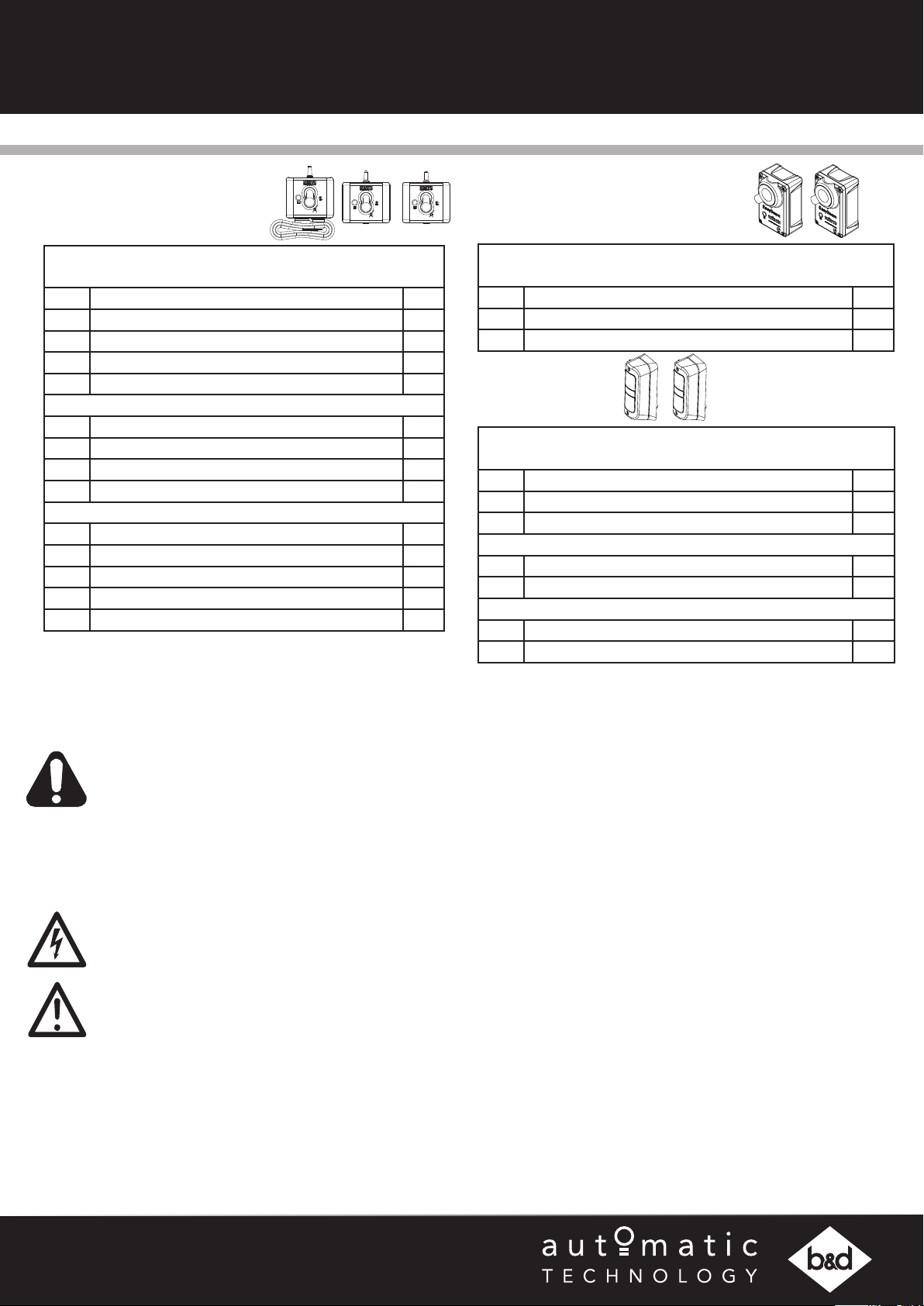
WPE-1V1 KIT -
ATA ORDER NO. 61957, B&D ORDER NO. 70300
ITEM DESCRIPTION QTY
1 WPB-04.02 TX ASSEMBLY 1
2 WPB-04.02 RX ASSEMBLY 1
3 WPB-04.03 BASE STATION ASSEMBLY 1
4 MOUNTING KIT 1
FLUSH MOUNTING KIT -
5 PEB4-W1 BRACKET 2
6 TAPTITE SCREW “P” M3 X 8 8
7 SELF TAPPING SCREW M6 X 25 4
8 PLASTIC WALL PLUG 6.7 X 25 4
PEB4-W1 HARDWARE KIT 2 -
9 PLASTIC WALL PLUG 6.9 X 25 2
10 SELF TAPPING SCREW M6 X 25 2
11 TAPTITE SCREW “P” BLACK ZNC M3 X 12 8
12 HEX SERRATION FLANGE NUT M6 1
13 HEX SERRATION HEAD SCREW M6 X 16 1
EasyBeamTM PE-3v1
EASYBEAM P.E. 3-V1 KIT
ATA ORDER NO. 61904, B&D ORDER NO. 62626
ITEM DESCRIPTION QTY
14 EASYBEAM RX-TX SET 1
4 MOUNTING KIT 1
PE 2000TS
PE 2000TS KIT -
ATA ORDER NO. 61903, B&D ORDER NO. 62852
ITEM DESCRIPTION QTY
15 PE BEAM IR-2000TS 1
4 MOUNTING KIT 1
ACCESSORY KIT -
16 RESISTOR 2K2 PACK 1
17 RESISTOR 5K6 PACK 1
INTERFACE KIT V2 (ACB / DCB BOARDS ONLY) -
18 HARNESS P.E. RX 24AWG 10M 1
19 HARNESS P.E. RX-TX 17M 1
Important Safety Instructions
WARNING!
ELECTROCUTION!
CAUTION:
Fall from ladder • Ensure ladder is the correct type for job.
Entrapment • Ensure the garage door / gate is in good working order by undertaking regular servicing.
• When using Safety beams, the doorway / gateway must be clear of all obstructions and
persons a all times. The location of the beams and manner in which they are installed
might not give safety protection at all times.
• The sensors need to be 100mm above the floor level, however, the exact position must
be chosen in such a manner that it suits the application, the environmental conditions
and provides maximum safety protection.
• When using auto close mode, a Safety beam must be fitted correctly and tested for
operation at regular intervals. Extreme caution is recommended when using auto close
mode. All safety rules must be followed.
• Disconnect the power cord from mains power and battery backup (if installed) before
making any repairs or removing covers on openers.
• Ensure ladder is on flat ground.
• Ensure user has 3 points of contact while on ladder.
• Safety beams must be installed if the closing force at the bottom edge of the door / gate
exceeds 400N (40kg)
Doc # 160044_07
Part # 13409
Released 14/12/17
Page 2
Safety Beam Compatibility
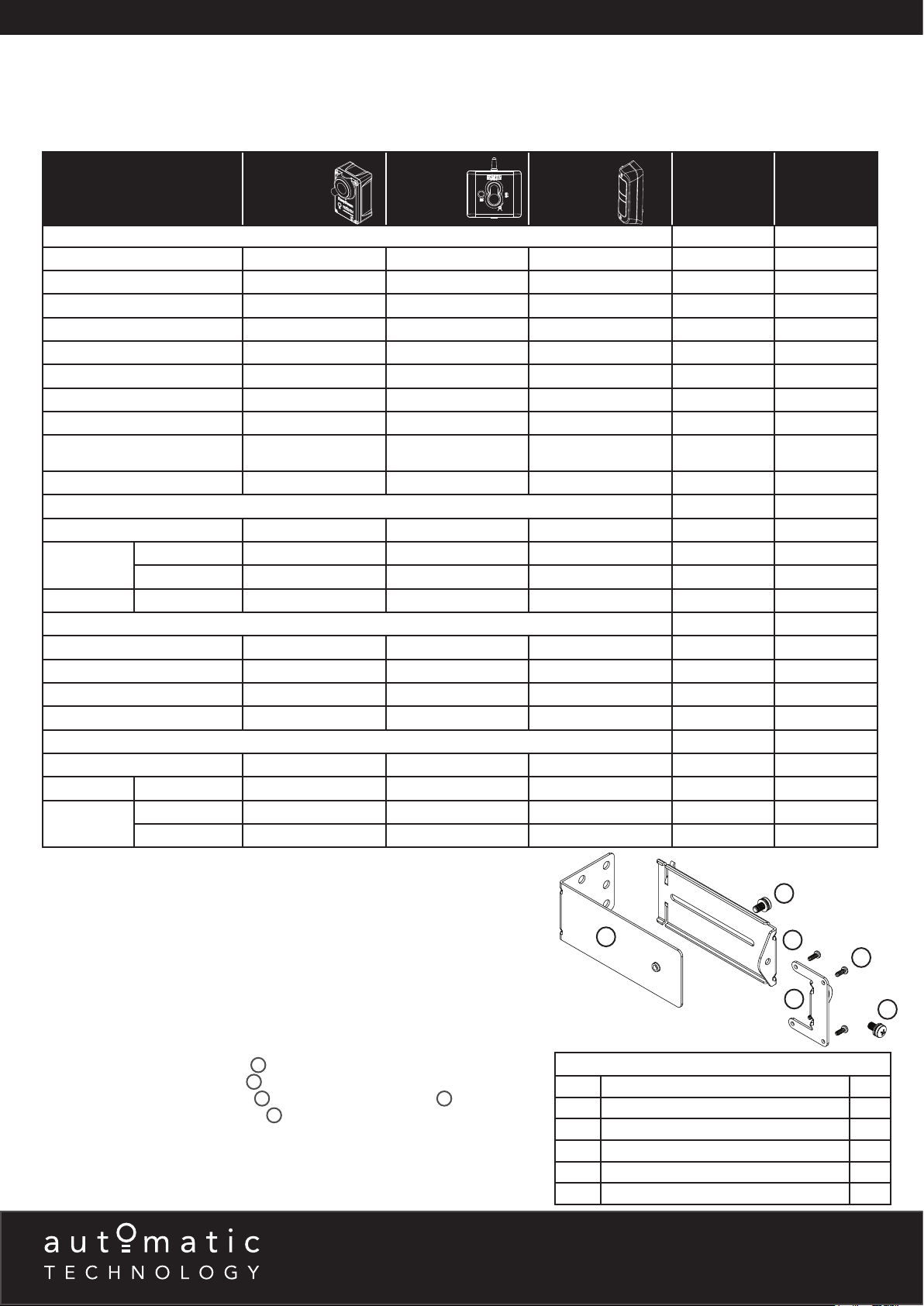
Safety Beams (SB) extend across the opening. The Safety Beam is designed to detect an obstruction while the door / gate is closing
and to send a signal to the opener to reverse or stop the door / gate movement. There are three (3) different types of Safety Beam
Kits available and they are not compatible with all products. Please refer to table below for product and Safety Beam compatibility.
PRODUCT
GARAGE DOOR OPENERS
GDO-6V3
GDO-6V4
GDO-8V3
GDO-9V2, GDO-9V3
GDO-9V2G2, GDO-9V3G2
GDO-11V1,
RDO-1V3, RDO-1V4
SDO-2V1, SDO-3V1
SDO-2V2, SDO-3V2,
ADVANCE & PRODIGY
SDO-4V1, GDO-11V3
LIGHT COMMERCIAL OPENERS
GDO-10V1
GDO-10V2
GDO-10V3L2 L2 CONSOLE
GATE OPENERS
DCB-05
DCB-05V2
NEOSLIDER NES24
NEOSLIDER V2, NEOSLIDER V3
INDUSTRIAL OPENERS
AXESS 1101
AXESS 1505 L2 CONSOLE
AXESS 3000
PRO SERIES
L1 CONSOLE
L2 CONSOLE
L1 CONSOLE
L2 CONSOLE
EASYBEAM WIRELESS PE 2000TS
• •
• •
• •
• •
• •
• • •
• •
• •
• • •
• • •
• •
• • •
• •
NO. OF SB
INPUTS
•
•
•
•
•
•
•
•
•
x 1 2.2K
x 2
x 1 2.2K
x 1 2.2K
x 2
x 1 2.2K
x 2
x 1 2.2K
x 2
x 2
x 1 5.6K
x 1 5.6K
x 3
x 3
x 1 5.6K
x 2 5.6K
x 1 5.6K
x 2 5.6K
x 1 5.6K
x 3
x 1 5.6K
x 3
RESISTOR
Mounting Brackets
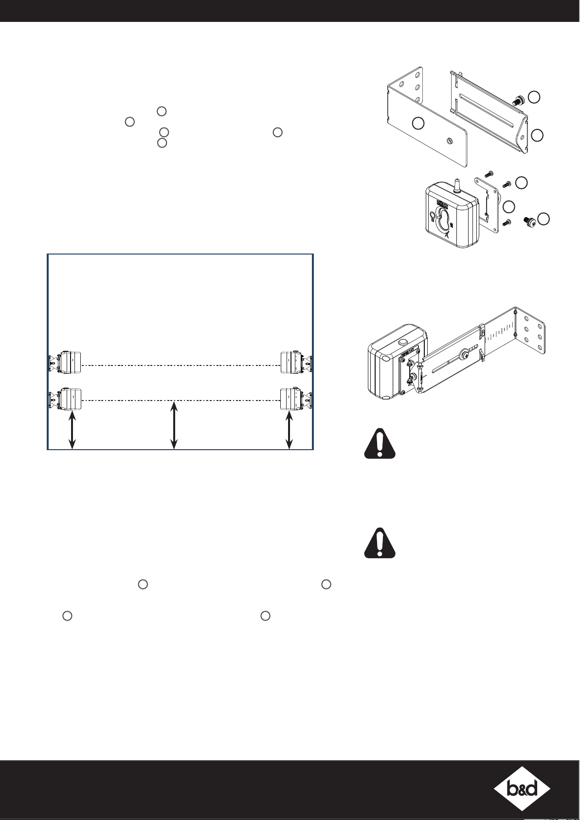
All three (3) types of Safety Beam Kits use the same mounting brackets.
Mounting Kit for all Safety Beams
NOTE: Mount the receiver on the side of the doorway / gateway closest to the
opener / console.
Assembling the Mounting Bracket
a. Attach the PE 2000TS Bracket 1 to the Safety Beam Transmitter (TX) using
four (4) M3 x 5 Taptite screws 4.
b. Connect the mounting bracket 3 to the adjustment bracket 2 with two (2)
of the M5 x 10 Pan Head Screws 5.
c. Repeat steps (a) and (b) to assemble the Safety Beam Receiver (RX).
d. Mount the receiver on the side of the doorway / gateway closest to the
opener / console and the transmitter on the other side in line with the receiver.
The mounting surface should be rigid. Affix with a minimum of four (4) screws
(not supplied).
6 - 8 Fiveways Boulevard, Keysborough, VIC, Australia 3173
P: 1300 133 944 E: [email protected]
W: www.automatictechnology.com.au
5
3
Right side
2
4
1
bracket
MOUNTING KIT
ITEM DESCRIPTION QTY
1 PE 2000TS BRACKET 2
2 ADJUSTMENT BRACKET 2
3 MOUNTING BRACKET 2
4 TAPTITE SCREW “B” PH M3 X 5 ZNC 8
5 PAN HEAD SCREW W/WASHER M5 X 10 4
5
Page 3
EasyBeam
TRANSMITTER
RECEIVER
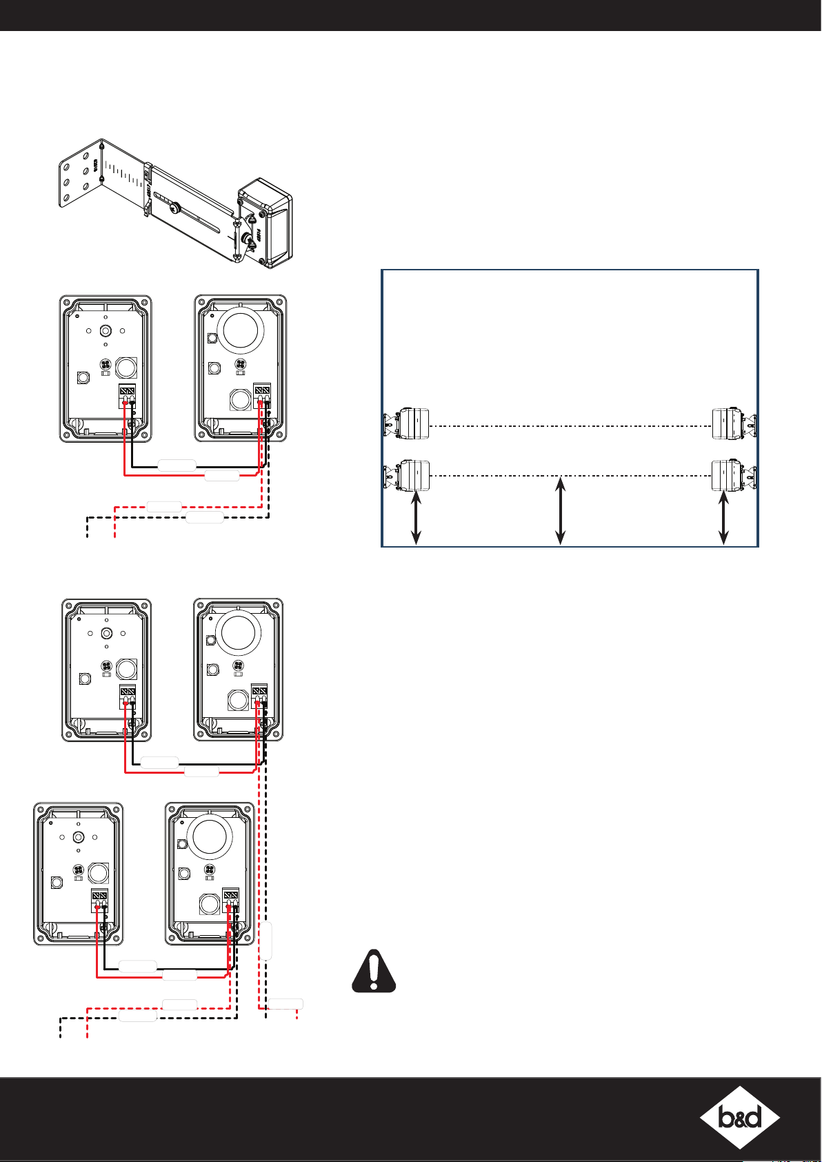
0V EB1 OR EB2 (OPENERS)
V- IN2 (C01L - CONSOLES)
0V SB1 OR SB2 (C02L - CONSOLES & GATES)
0V SB2 (C02L - CONSOLES
Refer to compatibility table (page 2) for Product compatibility.
Left side
bracket
Kit PE-3v1
NOTE: Mount the receiver on the side of the doorway / gateway closest to the
opener / console.
Assembling the Mounting Bracket
Assemble the mounting bracket as per instructions on page 2.
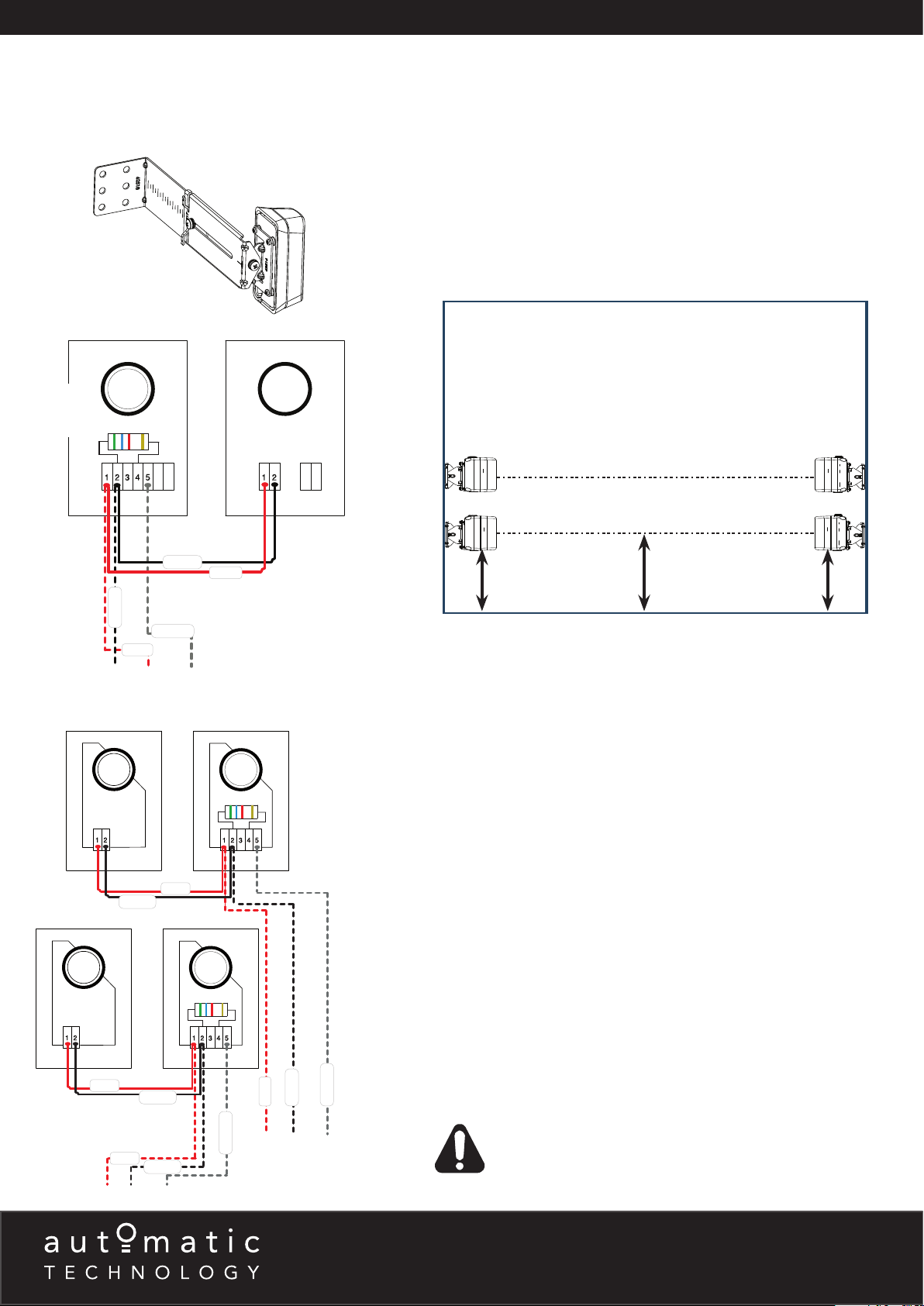
NOTE: When using two (2) sets of Safety Beams within the opening you must
alternative the configuration. See diagram below.
TM
One (1) set
Two (2) sets
TRANSMITTER
Black
Red
TRANSMITTER
TRANSMITTER RECEIVER
Black
Red
Black
Red
RECEIVER
TX - 2
RX - 2
TX - 1RX - 1
65mm
ATA recommends the transmitter and receiver are placed in line of sight, with the
beam 100mm above the ground level (as per AS60335). This can be achieved
by ensuring the bottom of the receiver and transmitter are 65mm above ground
level. They should also be placed as close as possible to the door / gate
opening.In industrial applications it is recommended that multiple Safety Beams
are fitted.
Wiring the EasyBeam
a. Connect the EasyBeam
diagram for one (1) set of safety beams or second wiring diagram for two (2)
sets of safety beams.
Aligning the Transmitter and Receiver
a. Power up the opener with the safety beams connected. The green LED on the
transmitter should turn ON to indicate power is present.
b. If the receiver is connected to power and the red LED is flashing while the
green LED on the transmitter is on, the transmitter and receiver are not
aligned.
c. Make horizontal and/or vertical adjustment on the transmitter and/or receiver
until the red LED on the receiver turns on, indicating alignment.
Setting the limits
After aligning the safety beams, refer to the openers manual to set the travel
limits. If opener has been installed previously, ensure you clear the limits and
follows instructions to set limits again.
TM
PE-3v1
TM
to the opener / console as per the first wiring
100mm
Floor Level
65mm
Black
Black
0V EB1 (OPENERS)
0V SB1 (C02L - CONSOLES & GATES)
Red
Red
Black
Red
0V EB2 (OPENERS)
& GATES)
WARNING! When using PE Beams, the doorway must be clear
of all obstructions and persons at all times. The location of the
beams and manner in which it is installed might not give safety
protection at all times. Check to make sure that the height of the
beam and type used give maximum protection possible.
B&D Doors is a division of B&D Australia Pty Ltd
P: 13 62 63
W: www.bnd.com.au
Page 4
Wireless Kit WPE-1v1
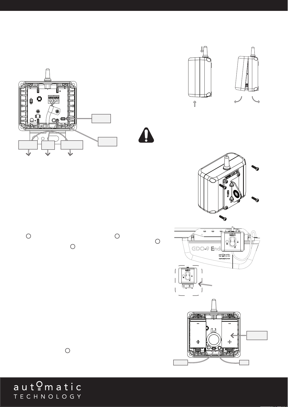
0V V+ EB1 OR EB2 (OPENERS)
COM V+ IN2 (C01L - CONSOLES)
0V V+ SB1, SB2 OR SB3 (C02L - CONSOLES & GATES)
Refer to compatibility table (page 2) for Product compatibility.
Wiring the Base Station to the Opener
a. Power off Opener.
b. Connect the Wireless WPE-1v1 Base Station to the opener / console as per
wiring diagram below.
RESET
WARNING! When using the C01L Console ensure that the
“PE Beam Type” (Menu 6.4) is set to “2-wire” mode
BLACK
NOTE: Multiple Sets of Wireless WPE-1v1 can be connected to certain openers
and the C02L Console. Gather the set of black wires together and insert into the
same terminal as per above wiring diagram. The same process applies to the red
wires. The yellow wires are individually inserted into to EB1 and EB2 (openers) or
SB1, SB2 and SB3 (C02L Console)
Fixing the Base Station to Wall/Opener
The base station can be fixed to the wall using the two (2) 6.9 x 25 plastic wall
plugs 9 and two (2) M6 x 25 self tapping screws 10. It can also be attached
directly to a sectional opener using the M6 x 16 Hex serration head screw 13 and
M6 Hex serration flange nut
the opener.
RED
YELLOW
12
. The wire can be fed through the top gromet of
LED
before setting limits.
Apply pressure here
Pull covers apart
NOTE: The bracket may also be rotated so the base station hangs above the
power head.
Inserting batteries into receiver and transmitter
a. Insert two (2) C-Type batteries in the Receiver (WPB-4.02 RX) by removing
the front cover.
b. The LED on the receiver will light up and after the communication is established
between the receiver and base station the LED on the base station and the
receiver will turn off. This can take up to 60secs.
c. Repeat step (a) to insert batteries into the Transmitter (WPB-4.02 TX).
d. The LED on the transmitter will light up and after communication is established
between the transmitter and base station the LED on the transmitter and on
the receiver will start to flash.
e. The flashing indicates the link is established between the transmitter and base
station, receiver and base station, but receiver and transmitter are not yet
alligned.
f. Put cover back on Transmitter and Receiver and secure with eight (8)
M6 x 25 screws (black)
11
.
6 - 8 Fiveways Boulevard, Keysborough, VIC, Australia 3173
P: 1300 133 944 E: [email protected]
W: www.automatictechnology.com.au
RESET
+
Base Station on the wall
BATTERY
+
LED
Receiver
Page 5
Wireless Kit WPE-1v1
Continued . . .
Assembling the Mounting Bracket
1
a. Attach the PE 2000TS Bracket
M3 x 5 Taptite screws 4.
b. Connect the mounting bracket 3 to the adjustment bracket 2 with two (2) of
the M5 x 10 Pan Head Screws 5.
c. Repeat steps (a) and (b) to assemble the Safety Beam Transmitter
(WPB-4.02TX).
d. Mount the receiver on the side of the doorway / gateway closest to the opener
/ console and the transmitter on the other side in line with the receiver. The
mounting surface should be rigid. Affix with a minimum of four (4) screws
(not supplied).
NOTE: When using two (2) sets of Safety Beams within the opening you must
alternative the configuration. See diagram below.
TX - 2
to the Receiver (WPB-4.02 RX) using four (4)
RX - 2
TX - 1RX - 1
5
3
2
Right side
bracket
4
1
5
NOTE: Mount the receiver on the side of
the doorway / gateway closest to the base
station.
Right side
bracket
assembled
65mm
e. ATA recommends the transmitter and receiver are placed in line of sight,
with the beam 100mm above the ground level (as per AS60335). This can be
achieved by ensuring the bottom of the receiver and transmitter are 65mm
above ground level. They should also be placed as close as possible to the
door / gate opening.In industrial applications it is recommended that multiple
Safety Beams are fitted.
Assemble Flush Mounting Kit (for minimum sideroom applications)
For applications which have limited space available or certain environmental
factors a flush mounting kit can be used.
a. Attached the transmitter (WPB-4.02TX) and receiver (WPB-4.02RX) to the
5
two (2) PEB4-W1 Bracket
b. Ensure to take note of the ATA recommendation in step (e) above and fix the
TX and RX to the wall or rigid surface using the two (2) 6.9 x 25 plastic wall
plugs 8 (if wall) and two (2) M6 x 25 self tapping screws 7.
Aligning the Transmitter and Receiver
a. Make horizontal and/or vertical adjustment on the transmitter until the red
LED on the receiver stays on, this indicates alignment.
b. Make horizontal and/or vertical adjustment on the receiver until the red LED
on the transmitter stays on, this indicates alignment.
Setting the limits
After aligning the safety beams, refer to the openers manual to set the travel
limits. If opener has been installed previously, ensure you clear the limits and
follows instructions to set limits again.
with the eight (8) M3 x 8 Taptite screws “P” 6.
100mm
Floor Level
65mm
WARNING! When using PE Beams, the
doorway must be clear of all obstructions
and persons at all times. The location
of the beams and manner in which it is
installed might not give safety protection
at all times. Check to make sure that the
height of the beam and type used give
maximum protection possible.
WARNING! PE beams must be installed
if the closing force at the bottom edge
of the door exceeds 400N (40kg force)
B&D Doors is a division of B&D Australia Pty Ltd
P: 13 62 63
W: www.bnd.com.au
Page 6
PE 2000TS Kit
RED
BLUE
GREEN
GOLD
+
+
-
-
6
7
0V PWR PE (OPENERS)
OUT V+ SB1 (GATES)
V- V+ IN3 (C01L - CONSOLES)
TRANSMITTERRECEIVER
RED
BLUE
GREEN
GOLD
+
+
-
-
RED
BLUE
GREEN
GOLD
+
+
-
-
TRANSMITTER
TRANSMITTER
RECEIVER
RECEIVER
PWR 0V PE (OPENERS)
V+ OUT2 SB1 (GATES)
PWR 0V PE (OPENERS)
V+ OUT2 SB2 (GATES)
Refer to compatibility table (page 2) for Product compatibility.
NOTE: Mount the receiver on the side of the doorway / gateway closest to the
opener / console.
Assembling the Mounting Bracket
Left side
bracket
5.6K
resistor
shown
Assemble the mounting bracket as per instructions on page 2.
NOTE: When using two (2) sets of Safety Beams within the opening you must
alternative the configuration. See diagram below.
TX - 2
RX - 2
TX - 1RX - 1
Black
Red
65mm
One (1) set
Black
Yellow
Red
Red
Black
a. ATA recommends the transmitter and receiver are placed in line of sight,
with the beam 100mm above the ground level (as per AS60335). This can be
achieved by ensuring the bottom of the receiver and transmitter are 65mm
above ground level. They should also be placed as close as possible to the
door / gate opening.In industrial applications it is recommended that multiple
Safety Beams are fitted.
Wiring the PE 2000TS
a. Power off the opener.
b. A resistor is required to detect a short in the wiring of the Safety Beam
Receiver. Only one of the resistors is to be used inside the Receiver. Refer to
compatibility table (page 2) for Product specific resistors.
c. Connect the PE 2000TS to the opener / console as per the first wiring diagram
for one (1) set of safety beams or second wiring diagram for two (2) sets of
safety beams.
Aligning the Transmitter and Receiver
a. Power up the opener with the safety beams connected. The green LED on the
transmitter should turn ON to indicate power is present.
b. If the receiver is connected to power and the red LED is flashing while the
green LED on the transmitter is on, the transmitter and receiver are not
aligned.
c. Make horizontal and/or vertical adjustment on the transmitter and/or receiver
until the red LED on the receiver turns on, indicating alignment.
100mm
Floor Level
65mm
Two (2) sets
Red
Red
Black
Black
Red
Yellow
Setting the limits
After aligning the safety beams, refer to the openers manual to set the travel
Black
Yellow
limits. If opener has been installed previously, ensure you clear the limits and
follows instructions to set limits again.
WARNING! When using PE Beams, the doorway must be clear of all
obstructions and persons at all times. The location of the beams and
manner in which it is installed might not give safety protection at all
times. Check to make sure that the height of the beam and type used
give maximum protection possible.
6 - 8 Fiveways Boulevard, Keysborough, VIC, Australia 3173
P: 1300 133 944 E: [email protected]
W: www.automatictechnology.com.au
Page 7
Troubleshooting
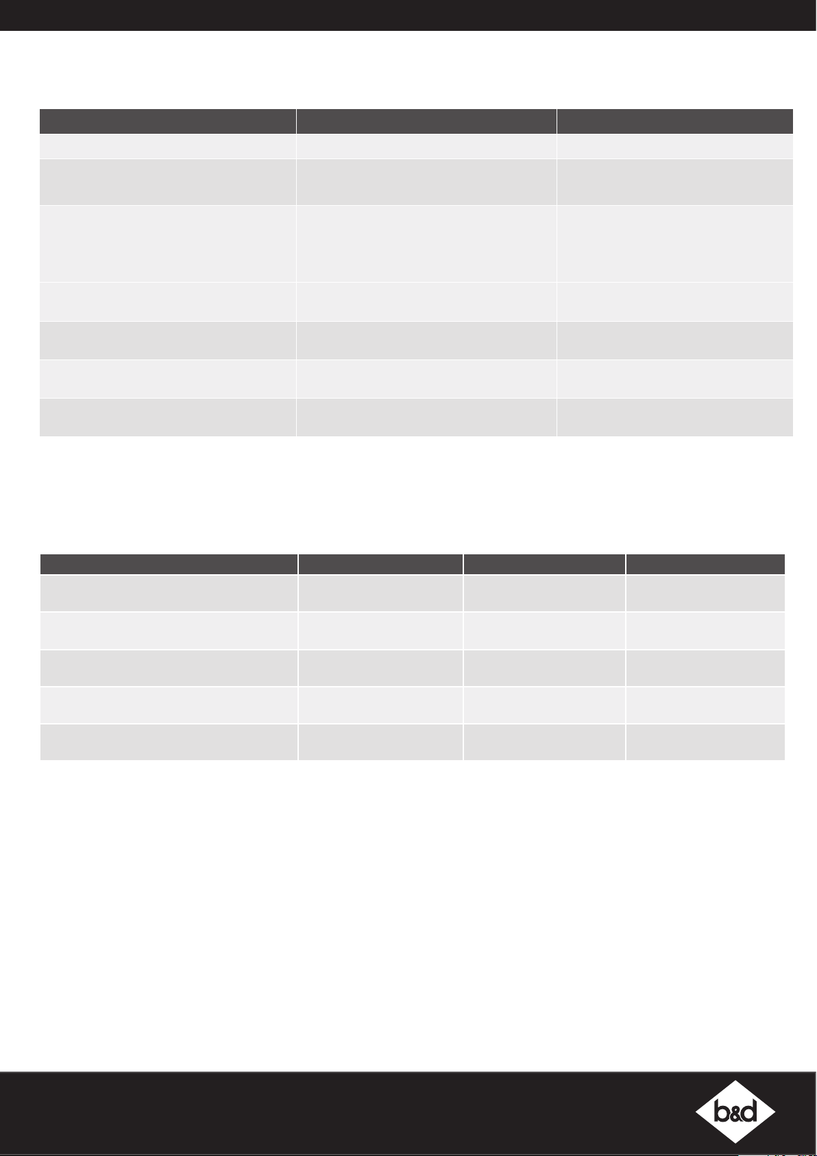
Symptom Possible cause Remedy
Base station and receiver LED’s constantly on Receiver is not coded into base station Code the receiver into base station
Receiver LED constantly on but cannot close
the door
Receiver LED is blinking and can not close
the door
During optical alignment transmitter LED
stopped working
During optical alignment receiver LED
stopped working
Wireless PE beam works ok but LED’s on
receiver and transmitter stopped working
LED on the receiver/transmitter started to
flash during operation of the door
Receiver not coded into base station
Mains power is not switched on to the opener
Receiver and transmitters not aligned
properly
Beam is obstructed Remove obstruction from the path of the
Setup timed out Press reset button on the transmitter.
Setup timed out Press reset button on the base station.
To save battery power LED on transmitter
turns off after number of cycles
The battery in the receiver/transmitter is
getting flat
Specifications
Technical Specifications EasyBeam
Code the receiver into base station.
Switch on mains power
Realign receiver and the transmitter
beam.
No remedy required.
Replace the batteries.
TM
Wireless PE 2000TS
Infrared beam range 20m 6m 20m
RF link range - 10m -
RF link frequency - 2.4 Ghz ISM Band -
Batteries for Wireless RX and TX - C-Type x 2 -
Battery Life - 3 years approx. -
Maintenance
To ensure a long and trouble free life for your Safety Beams, the following is recommended:
a. Periodically test the Safety Beam is operating efficiently by obstructing either the transmitter or receiver during the openers
operation to ensure the door / gate stops.
b. If the Safety Beams are located in a very dusty / dirty environment make sure to clean transmitter and receiver lenses for optimal
performance.
c. Replace batteries in transmitter or receiver (Wireless WPE-1V1 only) when they start to flash during operation of the door / gate.
B&D Doors is a division of B&D Australia Pty Ltd
P: 13 62 63
W: www.bnd.com.au
Page 8
Warranty and Exclusion of Liability
REGISTER ONLINE TODAY!
Register your Product to take advantage of convenient service and support at www.ata-aust.com.au/register
This Warranty is given by Automatic Technology (Australia) Pty Ltd (ABN 11 007 125 368) (ATA),
6-8 Fiveways Boulevard, Keysborough 3173, 1300 769 850, [email protected].
PLEASE NOTE:
• This Warranty is in addition to any statutory, non-excludable guarantees or warranty rights and remedies under the law. See section 5 below.
• This warranty applies to the original purchaser only and may not be transferred.
• This Warranty is to be read in conjunction with the owner’s copy of the installation instruction manual.
• In this warranty, ‘ATA Representative’ means an entity authorized by ATA to service ATA products. Please check the ATA website for details.
unsuitable electrical wiring of structures to which the product is affixed;
It is a condition of the below warranties that the
manual operating (opening and closing) force of the
door by hand does not exceed 20kg.
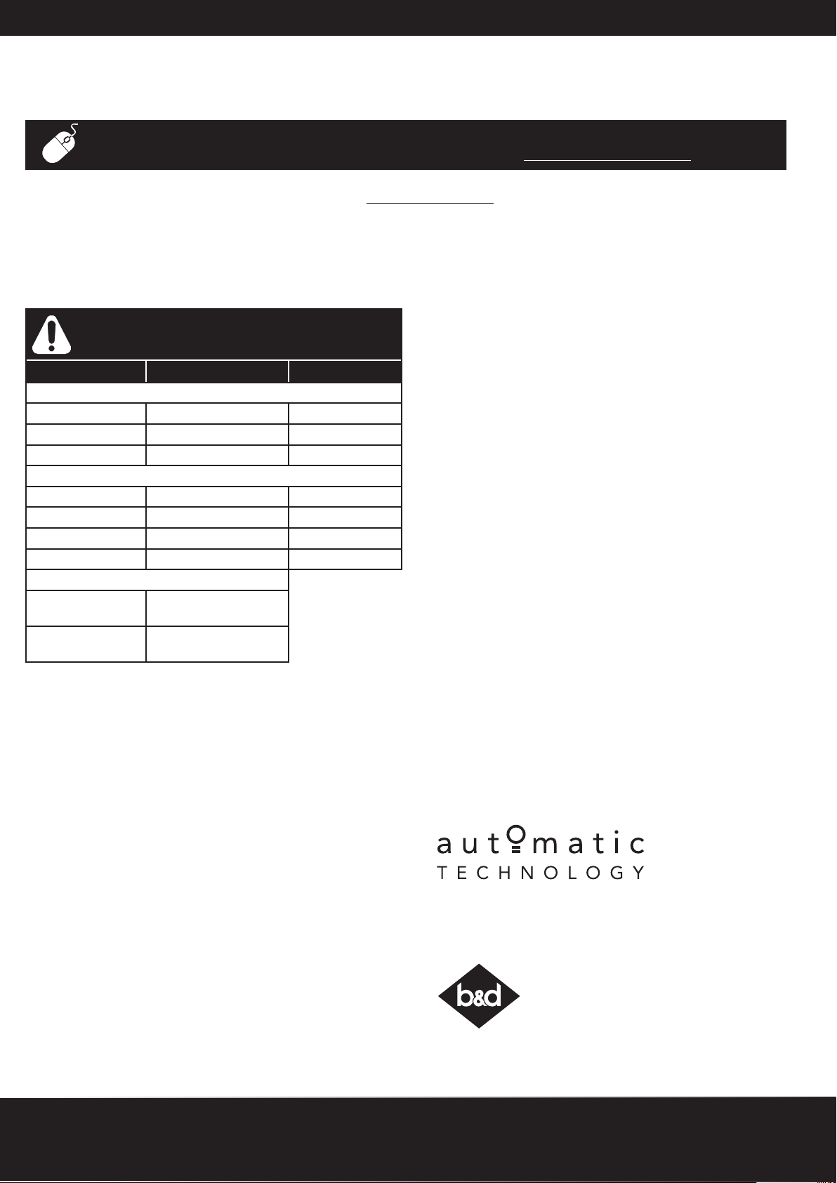
MODEL WARRANTY DOOR (MAX)
SECTIONAL
GDO-9V2 7 yrs / 20,000 cycles 200kg
GDO-9V3 7 yrs / 20,000 cycles 175kg
GDO-11V3 5 yrs / 10,000 cycles 110kg
ROLLING
GDO-6V3 5 yrs / 10,000 cycles 110kg
GDO-6V4 7 yrs / 20,000 cycles 110kg
GDO-8V3 2 yrs / 5,000 cycles 100kg
GDO-10V3 2 yrs / 5,000 cycles 270kg
EXTRAS
TRACK ASSEMBLY
1 year
(includes all parts)
TRANSMITTERS &
1 year
ACCESSORIES
NOTE: CONSUMABLES (eg Batteries in remote control transmitters and light bulbs
and fuses) are not covered by this warranty
1. MAKING A CLAIM
a. The product parts in the above table should operate in accordance with the
product manual for the time period shown, provided you comply with the
manufacturer’s instructions concerning installation, operation, maintenance and
testing. Failure to do so may void all or part of this warranty.
b. If, during the relevant warranty period, a product part in the table above
appears to contain a defect, call the retailer from whom you purchased the
product, or ATA on 03 9791 0240, and they will instruct you what to do next.
c. You are responsible for the cost of making a claim under this Warranty.
Additional access expenses where the Product is not readily accessible must
be borne by you.
d. If ATA or ATA’s Representative confirms the product is defective and covered by
this Warranty, ATA will repair or replace it (at ATA’s sole option) at no cost to you.
Goods presented for repair may be replaced or repaired by refurbished goods
or parts of the same type.
2. WARRANTY CONDITIONS
It is a condition of this warranty that:
a. you provide a copy of the receipt of original purchase of the product, and the
serial number of the Product which can be found on the label adhered to the
Product.
b. the Product has been serviced by ATA or an ATA Representative, within 12
months of installation (to allow for the door to settle) and at regular intervals
not exceeding 2 years.
3. WARRANTY EXCLUSIONS
This warranty excludes defecrts or improper operation resulting from:
a. excessive wear and tear that may cause the product to fail;
b. accidental, deliberate or negligent damage or damage cause by nsects,
dirt, plants or other objects;
c. blown fuses, electrical surges, power surges or power spikes or faulty or
d. theft, fire, flood, rain, water, lightning, storms or any other acts of God;
e. salt or other corrosion due to environmental conditions,
f. any installation, configuration or use of the product contrary to the instructions
supplied with the product;
g. maximum continuous operating time exceeding 1 minute in10 minutes;
h. the manual operating (opening and closing) force of the door by hand
exceeding 20kg;
i. weight exceeding amounts listed in table above;
j. the door used with the product not being in safe working order and condition;
k. any modification to the product or acts of any person in respect of the product
which are not authorized by ATA;
l. installation of a residential garage door opener in a commercial or industrial
premises or in a dwelling other than a single-family dwelling; or
m. radio or electrical interference or lack of availability of signal.
4. OTHER CONDITIONS
a. This Warranty is not transferable.
b. The warranty period stated in the table will not be extended for Products or
parts repaired or replaced during the relevant warranty period.
c. Where the Product is sold by any person other than ATA, except for the warranty
set out above, such person has no authority from ATA to give any warranty or
guarantee on ATA’s behalf in addition to the warranty set out above.
5. STATUTORY GUARANTEES OR WARRANTIES IN AUSTRALIA
If you are a consumer under the Australian Consumer Law, our goods come with
guarantees that cannot be excluded under the Australian Consumer Law. You are
entitled to a replacement or refund for a major failure and for compensation for any
other reasonably foreseeable loss or damage. You are also entitled to have the goods
repaired or replaced if the goods fail to be of acceptable quality and the failure does
not amount to a major failure.
This warranty certificate and other statements contained in this document or other ATA
documents given to you do not exclude, restrict or modify the application of all or any
of the provisions of the Australian Consumer Law.
Subject to your non-excludable rights under the Australian Consumer Law, ATA
expressly excludes any liability for consequential loss, incidental or indirect damages
(including but not limited to damages for loss of business profits, business interruption
and loss of business information) due to a defect of the Product. In particular, any loss
or damage caused to other equipment or accessories used with the product or any
loss resulting from a delay in repair is excluded to the extent permitted by law.
6 - 8 Fiveways Boulevard, Keysborough, VIC, Australia 3173
P: 1300 769 850 E: [email protected]
W: www.automatictechnology.com.au
B&D Doors is a division of B&D Australia Pty Ltd
ABN 25 010 473 971
B&D Doors, 34-36 Marigold St, Revesby, NSW, 2212
P: 13 62 63 E: [email protected]
W: www.bnd.com.au
© March 2014 Automatic Technology (Australia) Pty Ltd. All rights reserved. No par t of this document may be reproduced without prior permission. In an ongoing
commitment to product quality we reserve the right to change specification without notice. E&OE.
 Loading...