

Page 1
Battery Backup Kit
Gen 2
2.3 Ah V-06 Installation Instructions
Garage Door Openers
BATTERY BACKUP KIT 2.3Ah V-06 - SAP# NO. 62737
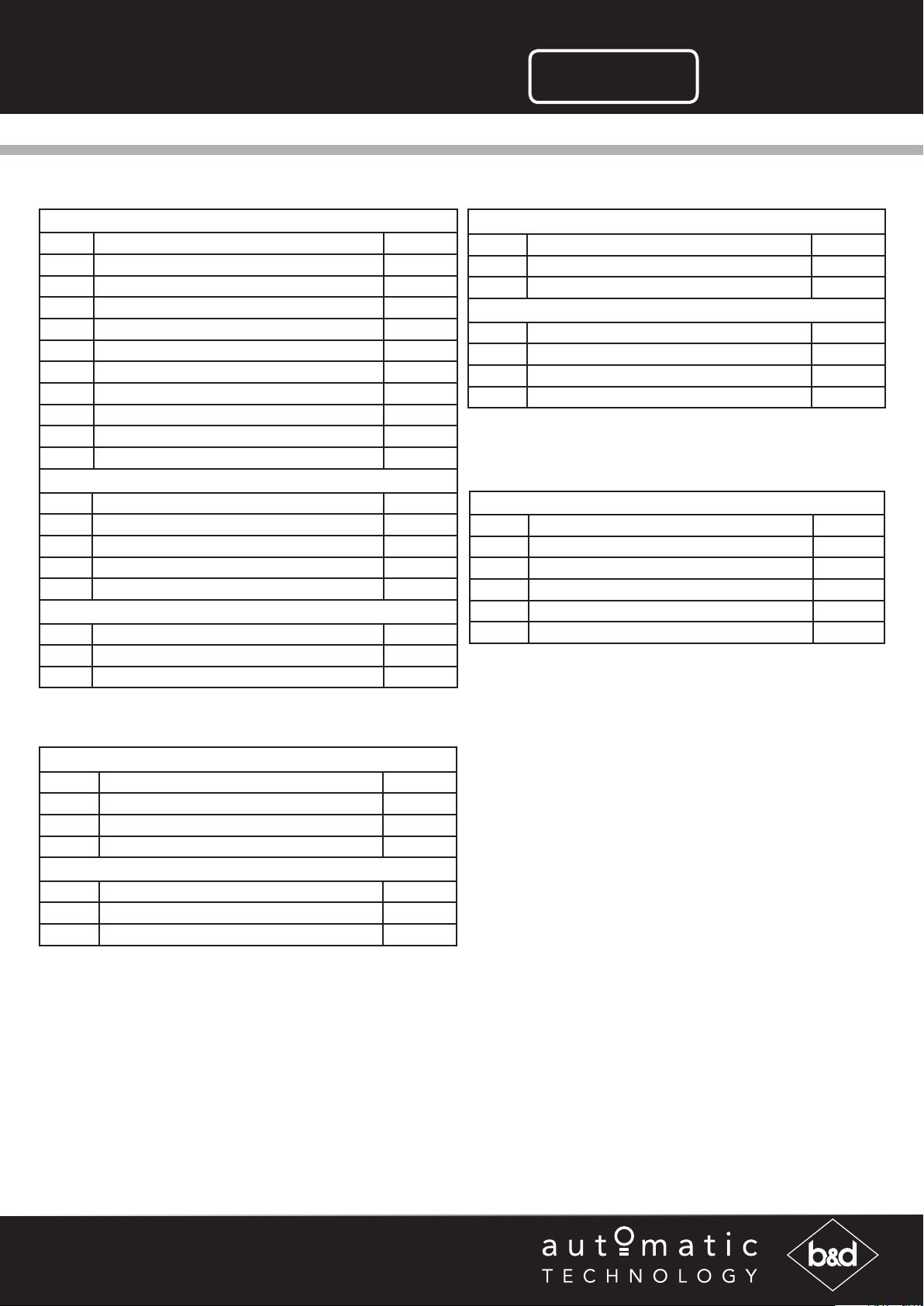
ITEM DESCRIPTION QTY
1 BATTERIES COVER 1
2 BATTERIES SUPPORT 1
3 BATTERY 12V SEC 12-2.2 AGM TYPE 2
4 BATTERY COUPLING WIRE - ESV24 1
5 BATTERY HARNESS 1
6 PAN HEAD SCREW W/WASHER M4x8 2
7 CABLE CLAMP ACC-1.5 (3/16”) 1
8 CHARGER BOARD SBC-02 1
9 SBC-02 CHARGER HARNESS 1
10 SBY-2 BATTERY HARNESS 1
PACK #1 (SECTIONAL DOOR OPENERS)
11 HEX STANDOFF M4 2
12 PAN HEAD SCREW W/WASHER M4x8 4
13 THRUSS SER HD SCREW “S” RoHS M4x8 2
14 TAPTITE SCREW “P” M4 X 8 3
15 PCB SUPPORT 76X27 1
PACK #2 (ROLLER DOOR OPENERS)
16 TAPTITE SCREW “P” M4x8 4
17 TAPTITE SCREW “P” M4x10 2
18 CABLE CLAMP ACC-1.5 (3/16”) 1
Swing Gate Openers
BATTERY BACKUP KIT SBC-02 - SAP# NO. MC0090
ITEM DESCRIPTION QTY
19 BATTERY CHARGER BOX ASSEMBLY 1
20 CHARGER ASSY SBC-02 1
ACCESSORY PACK
21 TIE MOUNT CM-13 (ADHIESIVE) 4
22 CABLE TIE 4” GT-100M 4
23 BRACKETS GE 44 621 4
24 SCREW “P” M3.5 X 13 FOR GW 44 621 4
Sliding Gate Openers
BATTERY BACKUP KIT ESV24V2 - SAP# NO. 69767
ITEM DESCRIPTION QTY
25 BATTERY CP1223H 12V 2.3H 2
26 CHARGER ASSY SBC-02 1
27 BATTERY COUPLING WIRE - ESV24 1
28 BATTERY HARNESS 1
29 TAPTITE SCREW “P” M3 X 8 4
Commerical Door Openers
BATTERY BACKUP KIT GDO-12 - SAP# NO. 86408
ITEM DESCRIPTION QTY
30 BATTERY 12PCA1.3 - 12V1.3AH 2
31 BATTERY COUPLING WIRE - F1 1
32 BATTERY HARNESS 1
OPTIONAL PACK 1# (WALL MOUNT) - SAP# NO. 86774
33 TAPTITE SCREW “P” M3.5 X 8 2
34 PLASTIC WALL PLUG 2
35 BATTERY HARNESS EXTENSION 1
Doc # 160018_04
Part # 13403
Released 20/11/18
Page 2
Important Safety Instructions
WARNING!
ELECTROCUTION!
• DO NOT short the output of batteries. Serious personal injury and/or property
damage can result from failure to follow this warning
• During charging and discharging cycles the lead-acid batteries may release explosive
gases. Ensure that the area around the batteries is well ventilated
• Take care not to allow any metal objects to make contact with the positive and negative
terminals. This will short circuit the battery causing sparks and possible damage to the
battery, or even cause an explosion.
• The battery box unit should be installed away from sprinkler systems.
• DO NOT immerse in water or spray directly with a hose or other device.
• Disconnect the power cord from mains power before making any repairs or removing
covers.
CAUTION:
Fall from ladder • Ensure ladder is the correct type for job.
• Ensure ladder is on flat ground.
• Ensure user has 3 points of contact while on ladder.
Burns • DO NOT handle damaged or leaking batteries
• Wear appropriate protective clothing and avoid touching your eyes after working with
batteries.
• The battery backup kit contains sealed lead-acid batteries that must be disposed of
properly at the end of their useful life.
Specifications
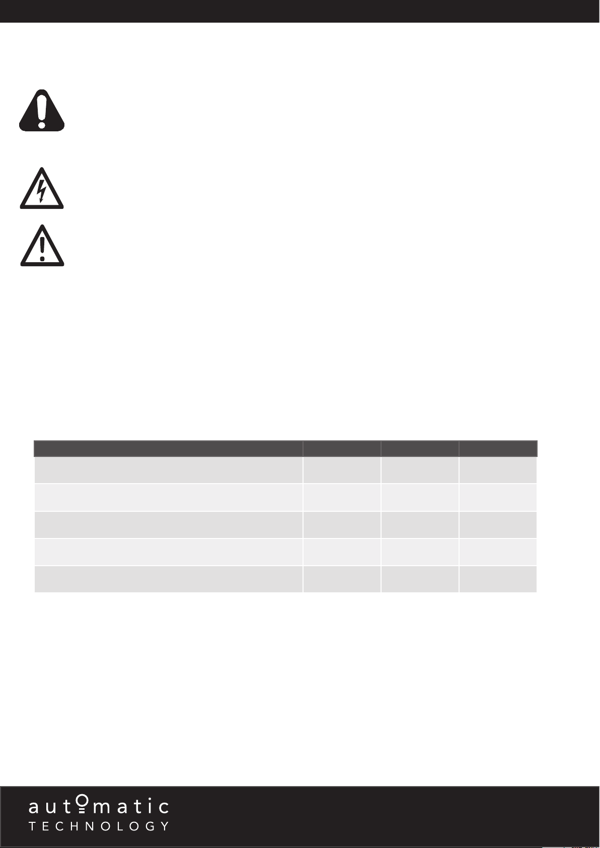
Battery Back up Specifications Garage Door Swing Slider
Approximate number of Cycles under battery power 10 10 10
Average Cycle Time under battery power (Opening and Closing) 40 seconds 90 seconds 90 seconds
Wire Gauge and Length from Battery to Charger board (max) 18AWG, 3m 18AWG, 3m 18AWG, 3m
Battery capacity (Amp Hours) 2.3 AH 2.3 AH 2.3 AH
Time for Re-charge 24 - 48 Hours 24 - 48 Hours 24 - 48 Hours
6 - 8 Fiveways Boulevard, Keysborough, VIC, Australia 3173
P: 1300 133 944 E: [email protected]
W: www.automatictechnology.com.au
Page 3
Grommet
Light Diffuser
Overhead Door Opener Set Up
GDO-9V2 GEN2 Enduro, GDO-9V3 GEN2 Dynamo, SDO-2V2 CAD P Diamond,
SDO-2V2 CAD Advance, SDO-2V3 CAD Prodigy & SDO-3V2 CAD S
SDO-2V3 Prodigy:
The Charger board is already installed with the unit.
Please proceed to Mount & Connect the Battery.
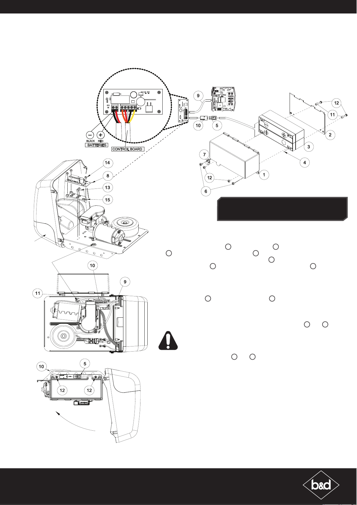
Mount the Charger Board
a. Unplug the drive unit from mains power.
b. Remove screws and swing open the cover.
c. Mount the PCB support 15 with two screws 13. Secure the charger board
8
on to PCB support with 3 screws 14.
d. Unscrew the 2-wire SBY-2 battery harness 10 from the 2 pin connector on
the charger board 8. Feed the 2-wire SBY-2 battery harness 10 through the
grommet on the base plate and secure back on the 2 pin connector.
e. Remove two (2) screws from the Light Diffuser to access the main control
board.
f. Remove the shunt from the 5 pin connector on the control board. Feed the
charger harness 9 from the charger board 8 through the cover and insert
into the 5 pin connector on the main control board.
Mount & Connect the Battery
a. Mount battery pack on side of unit and secure with items 11 and 12.
WARNING: After Step (b) the opener may become active (even when
power is off). This is a result of a residual charge in the batteries.
b. Connect battery harnesses 5 and 10 together.
c. Close the cover, secure the Light Diffuser with 2 screws and reconnect
power.
NOTE: Batteries may take up to 48 hours to charge fully after initial installation.
Re-setup and Test the Opener
a. Reconnect power and remove button cover.
b. Press either the OSC button the opener or the programmed transmitter
button to test the battery backup installation.
c. Whilst door is in motion, disconnect mains power. The door should continue
to operate as normal.
NOTE: Wait for the door to complete its travel.
d. Press either the OSC button on the opener or the progammed transmitter
button to activate the door.
e. Whilst door is in motion, reconnect power and re-install button cover. The
door should complete the cycle as normal.
B&D Doors is a division of B&D Australia Pty Ltd
P: 13 62 63
W: www.bnd.com.au
Page 4
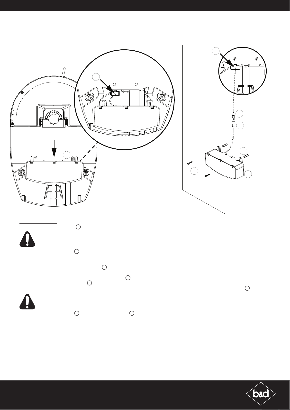
Roll Up Door Opener Set Up
GDO-6V4 EasyRoller®, RDO-1V3 & RDO-1V4
SBC-02
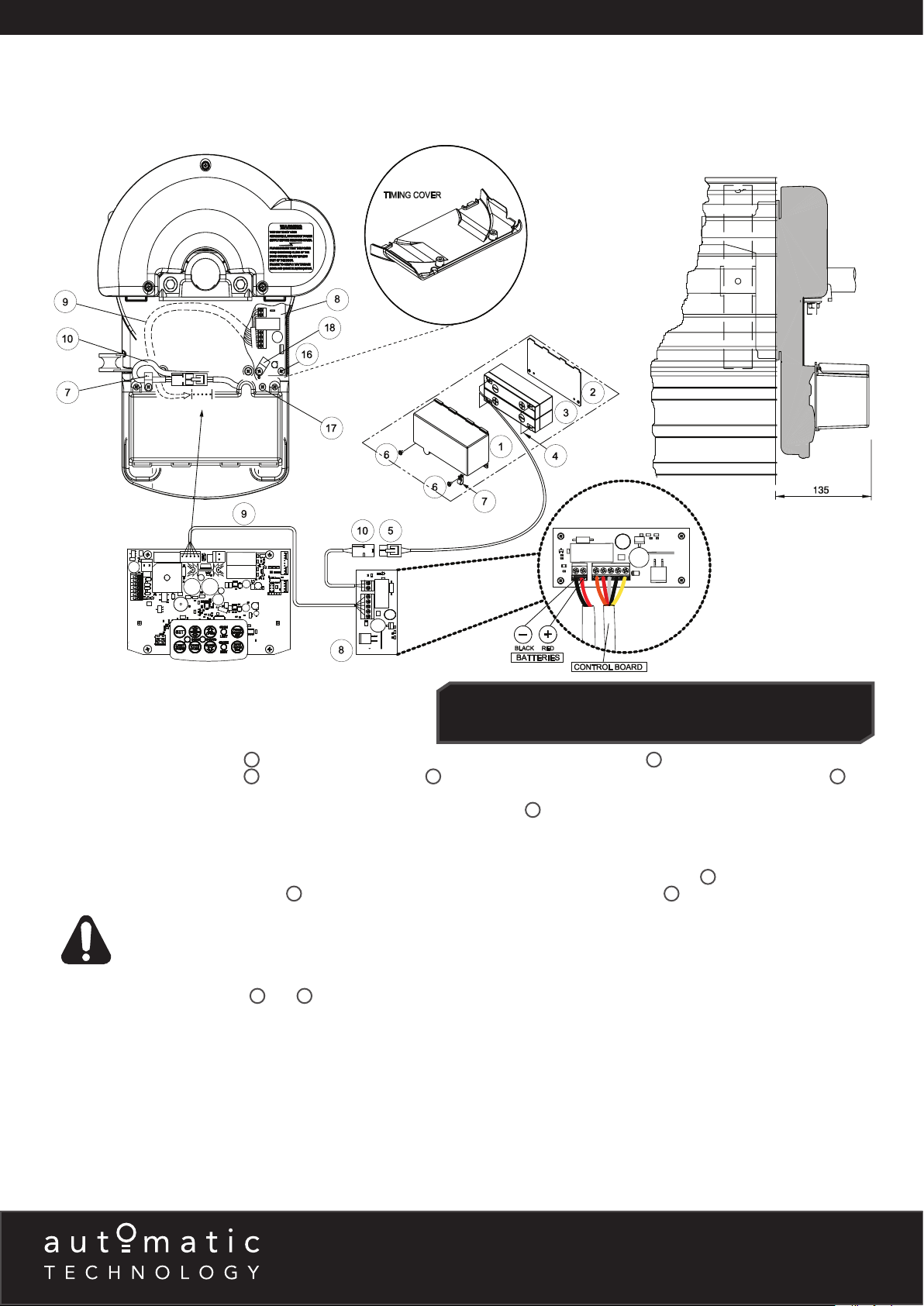
Mount the Charger Board
a. Unplug the drive unit from mains power.
b. Remove the timing cover and light diffuser.
c. Mount the Charger Board 8 on the chasis and secure with four (4) Taptite ‘P’ M4x8 screws 16.
d. Feed the battery harness 5 through the cable clamp 18 and secure left corner of the board. Feed the Wire Harness 9
around the timing assembly, through opening and plug into SBC-02 connector on the control board.
e. Remove breakaway slot on timing cover and feed wire battery harness 10 through slot and replace timing cover. Secure in
place with screws.
Mount & Connect the Battery
a. Mount battery backup kit onto support chassis and secure right side screw first (charger board side) 17.
b. Position the wire battery harness 10 neatly and secure left side of battery kit with cable clamp 7.
WARNING: After Step (c) the opener may become active (even when power is off).
This is a result of a residual charge in the batteries.
5
c. Connect battery harnesses
d. Close the timing cover, light diffuser and reconnect power.
NOTE: Batteries may take up to 48 hours to charge fully after initial installation.
Re-setup and Test the Opener
a. Reconnect power and remove the button cover.
b. Press either the OSC button the opener or the programmed transmitter button to test the battery backup installation.
c. Whilst door is in motion, disconnect mains power. The door should continue to operate as normal.
and 10 together.
RDO-1V4:
The Charger board is already installed with the unit. Remove the
timing cover then proceed to step (e) to remove breakaway slot.
NOTE: Wait for the door to complete its travel.
d. Press either the OSC button on the opener or the progammed transmitter button to activate the door.
e. Whilst door is in motion, reconnect power and re-install button cover. The door should complete the cycle as normal.
6 - 8 Fiveways Boulevard, Keysborough, VIC, Australia 3173
P: 1300 133 944 E: [email protected]
W: www.automatictechnology.com.au
Page 5
Commercial Door Opener Set Up
GDO-12V1 Hiro
35
32
35
32
30
Opener Mounted
Mount & Connect the Battery
Openers Mounted
a. Mount battery backup kit 30 onto support chassis by sliding down over the slots.
WARNING: After Step (b) the opener may become active (even when power is off).
This is a result of a residual charge in the batteries.
b. Connect battery harness 32 plug through opening to control board.
Wall Mounted
a. Connect the battery harness extension 35 plug through the opening in the opener to the control board.
b. To wall mount - use the battery pack as template to mark where to drill holes. Pre-drill holes.
i. For plaster walls - insert (2) two Plast wall plugs 34 into holes, place battery backup kit over holes and affix with (2) two
Taptite “P” M3.5 x 8 screws 33.
ii. For brick walls - place the battery backup kit over the holes and affix with (2) two Taptite “P” M3.5 x 8 screws 33.
33
34
30
Wall Mounted
WARNING: After Step (b) the opener may become active (even when power is off).
This is a result of a residual charge in the batteries.
c. Connect battery harness
NOTE: Batteries may take up to 48 hours to charge fully after initial installation.
Re-setup and Test the Opener
a. Reconnect power and remove the button cover.
b. Press the programmed transmitter button to test the battery backup installation.
c. Whilst door is in motion, disconnect mains power. The door should continue to operate as normal.
NOTE: Wait for the door to complete its travel.
d. Press the progammed transmitter button to activate the door.
e. Whilst door is in motion, reconnect power and re-install button cover. The door should complete the cycle as normal.
32
to the harness extension 35.
B&D Doors is a division of B&D Australia Pty Ltd
P: 13 62 63
W: www.bnd.com.au
Page 6
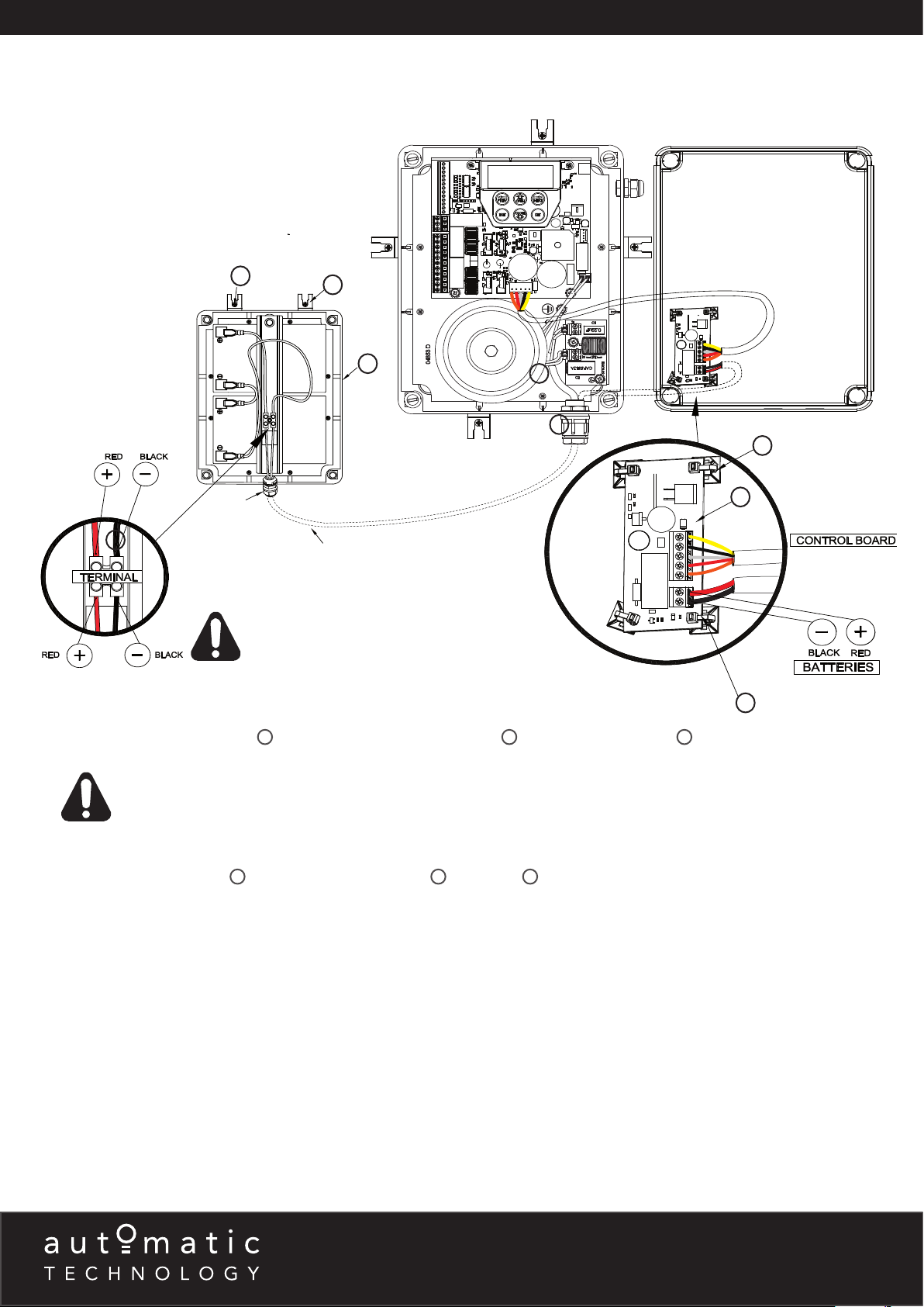
Swing Gate Opener Set Up
DCB-05V2
24
1
WARNING! Do not connect the batteries until
you have connected wiring on the charger
board.
Mount the Charger Board
a. Unplug the Control Box from mains power.
b. Remove the Control Box’s cover.
c. Secure the adhesive mounts
d. Plug the Charger Board’s five wire harness (orange/red/white/black/yellow) into the DCB-05 board’s “SBC-02” connector.
21
to the Charger Board with cable ties 22. Affix the Charger Board 20 inside the the Control Box cover.
23
19
9
8
21
20
22
WARNING! The opener will become active
during the following steps.
Mount & Connect the Battery
a. Drill a hole in the Battery Pack enclosure (recommend at the bottom) and fit a nylon gland (not supplied).
b. Mount the Battery Pack 19 using the mounting brackets 23 and screws 24 close to the control box.
c. Feed a 2-core 18awg gauge cable (not supplied) through the Battery Box’s nylon gland.
d. Connect the red wire to the Battery Box’s “+” terminal, and the black wire to the “–” terminal
e. Feed the other end of the 2-core 18awg gauge cable through the control box’s gland.
f. Connect the red wire to the Charger Board’s Battery Harness“BAT+” connector, and the black wire to the “–BAT” connector.
Re-setup and Test the Opener
a. Reconnect power.
b. Select Menu 7 on the DCB-05 control board, press “SET”, select Sub Menu 7 (“Battery/Solar”) and enable using the “OPEN” and
CLOSE” buttons.
c. Setup travel limits and transmitters as per the DCB-05V2 instruction manual.
d. Press either “OPEN” or “CLOSE” buttons, or use a transmitter to operate the gate.
e. Whilst the gate is in motion, disconnect mains power. The gate should continue to operate as normal.
NOTE: Wait for the gate to complete its travel.
f. Press the transmitter to activate the gate. Whilst the gate is in motion re-connect power. The gate should complete the cycle as
normal.
g. Refit the control box cover.
6 - 8 Fiveways Boulevard, Keysborough, VIC, Australia 3173
P: 1300 133 944 E: [email protected]
W: www.automatictechnology.com.au
Page 7
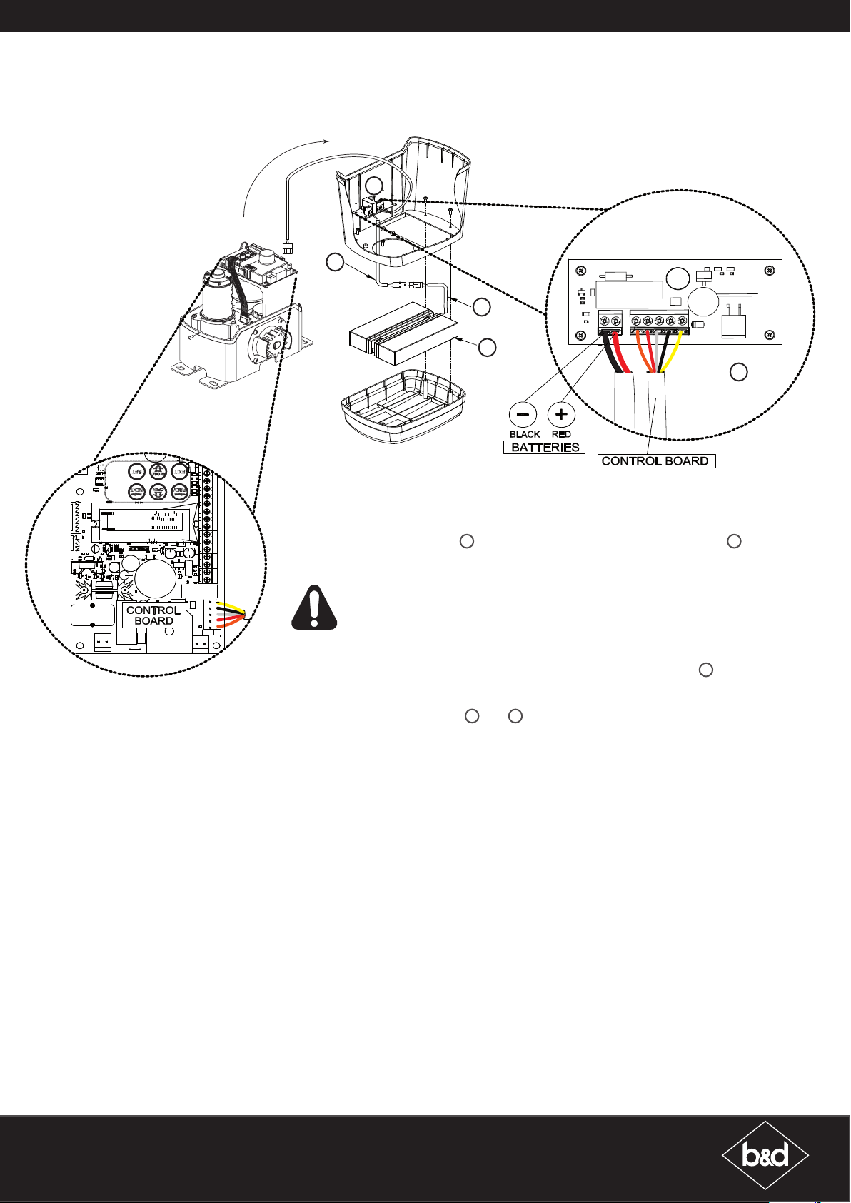
Sliding Gate Opener Set Up
NeoSliderTMV2, NeoSliderTMV3
29
28
27
25
Mount the Charger Board
a. Unplug the drive unit from mains power.
b. Remove the main cover and unscrew the lid from the cover.
c. Mount the Charger Board 26 inside the cover using four (4) M3x8 screws 29.
d. Plug the Charger Board’s five wire harness (orange/red/white/black/yellow) into the
control board’s “SBC-02” connector.
26
WARNING: After Step (c) the opener may become active (even when power is
off). This is a result of a residual charge in the batteries.
Mount & Connect the Battery
a. Place the battery pack inside the lid and feed battery coupling wire 27 through the main
cover.
b. Secure the lid to the main cover with screws.
c. Connect battery harnesses 27 and 28 together.
NOTE: Batteries may take up to 48 hours to charge fully after initial installation.
Re-setup and Test the Opener
a. Reconnect power.
b. Select Menu 7 on the control board, press “SET”, select Sub Menu 7 (“Battery/Solar”) and
enable using the “OPEN” and CLOSE” buttons.
c. Setup travel limits and transmitters as per the slider instruction manual.
d. Press either “OPEN” or “CLOSE” buttons, or use a transmitter to operate the gate.
e. Whilst the gate is in motion, disconnect mains power. The gate should continue to operate
as normal.
NOTE: Wait for the gate to complete its travel.
f. Press the transmitter to activate the gate. Whilst the gate is in motion re-connect power.
The gate should complete the cycle as normal.
g. Refit the main cover onto the drive unit.
B&D Doors is a division of B&D Australia Pty Ltd
P: 13 62 63
W: www.bnd.com.au
Page 8
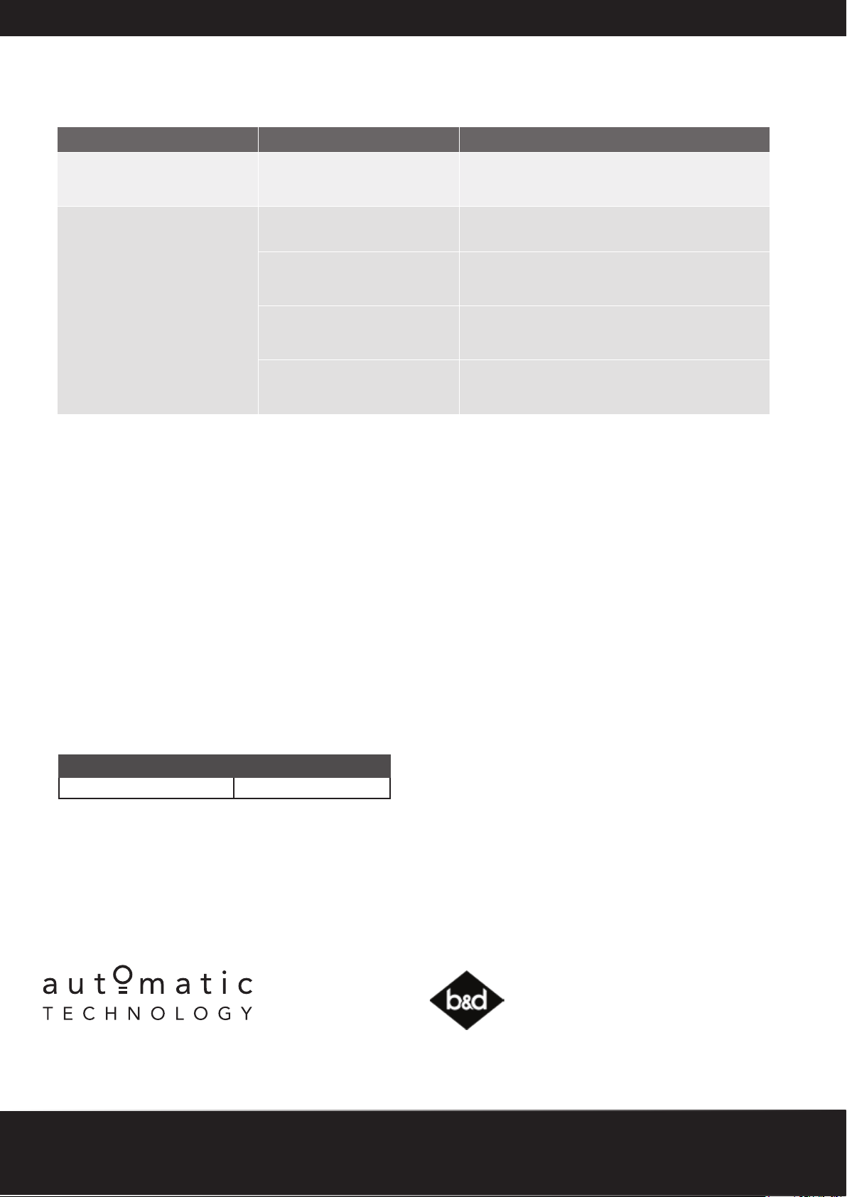
Troubleshooting
Symptom Possible cause Remedy
Door stops or moves very slowly
under battery power
Door will not operate when
mains power is disconnected.
Batteries may be weak or have
no charge
Batteries / charger board may
not be connected properly.
Batteries may have no charge Connect mains power and allow the batteries
Faulty Charger board Disconnect the charger board from batteries and
Faulty Batteries Disconnect the batteries from the charger board.
Connect mains power and allow the batteries
to charge. This may take 24 - 48 hours to reach
maximum charge capacity.
Check wiring.
to charge. This may take 24 - 48 hours to reach
maximum charge capacity.
control board. Check voltage of the charger board.
Voltage should be approximately 27.5V.
Check the voltage of the each battery. Voltage
should not drop below 10V.
Maintenance
To ensure a long trouble free life for your battery backup it is recommended you run the testing procedure on a monthly basis.
Batteries should not need replacing for 4 - 5 years.
Testing Procedure:
a. Press the transmitter to activate the opener.
b. Whilst the door / gate is in motion disconnect power. The door / gate should complete the cycle as normal.
c. Wait for the door / gate to finish is travel.
d. Press the transmitter to activate the opener.
e. Whilst the door / gate is in motion reconnect power. If the door / gate stopped or moved very slosly under battery power,
ensure mains power is connected for 24 - 48 hours to recharge the batteries. Test the opener again under battery power to
ensure batteries are working effectively.
Warranty
WARRANTY
ACCESSORIES 1 year
6 - 8 Fiveways Boulevard, Keysborough, VIC, Australia 3173
P: 1300 133 944 E: [email protected]
W: www.automatictechnology.com.au
© Nov 2018 Automatic Technology (Australia) Pty Ltd. All rights reserved. No part of this document may be reproduced without prior permission. In an ongoing
commitment to product quality we reserve the right to change specification without notice. E&OE.
This warranty is to be read in conjunction with the owner’s copy of
the opener installation instruction.
B&D Doors is a division of B&D Australia Pty Ltd
ABN 25 010 473 971
B&D Doors, 34-36 Marigold St, Revesby, NSW, 2212
P: 13 62 63 E: [email protected]
W: www.bnd.com.au
 Loading...