

Page 1

bdbiosciences.com
23-11165-00 Rev. A
1/2010
For Research Use Only. Not for use in diagnostic or therapeutic procedures.
HTS Customer Care
Kits
User’s Guide
Becton, Dickinson and Company
BD Biosciences
San Jose, CA 95131
Tel 877.232.8995
Fax 800.325.9637
[email protected]
Asia Pacific
Tel 65.6.861.0633
Fax 65.6.860.1593
Europe
Tel 32.2.400.98.95
Fax 32.2.401.70.94
[email protected]
Brazil
Tel 55.11.5185.9995
Fax 55.11.5185.9895
[email protected]
Japan
Nippon Becton Dickinson Company, Ltd.
Toll Free 0120.8555.90
Tel 81.24.593.5405
Fax 81.24.593.5761
Canada
Toll Free 888.259.0187
Tel 905.288.6000
Fax 888.229.9918
[email protected]
Mexico
Toll Free 01.800.236.2543
Tel 52.55.5999.8296
Fax 52.55.5999.8288
[email protected]
Page 2

© 2010, Becton, Dickinson and Company. All rights reserved. No part of this publication may be reproduced,
transmitted, transcribed, stored in retrieval systems, or translated into any language or computer language, in any
form or by any means: electronic, mechanical, magnetic, optical, chemical, manual, or otherwise, without prior
written permission from BD Biosciences.
The information in this guide is subject to change without notice. BD Biosciences reserves the right to change its
products and services at any time to incorporate the latest technological developments. Although this guide has been
prepared with every precaution to ensure accuracy, BD Biosciences assumes no liability for any errors or omissions,
nor for any damages resulting from the application or use of this information. BD Biosciences welcomes customer
input on corrections and suggestions for improvement.
BD, BD Logo and all other trademarks are property of Becton, Dickinson and Company. © 2010 BD
FCC Information
WARNING: Changes or modifications to this unit not expressly approved by the party responsible for compliance
could void the user’s authority to operate the equipment.
NOTICE: This equipment has been tested and found to comply with the limits for a Class A digital device, pursuant
to Part 15 of the FCC Rules. These limits are designed to provide reasonable protection against harmful interference
when the equipment is operated in a commercial environment. This equipment generates, uses, and can radiate radio
frequency energy and, if not installed and used in accordance with the instruction manual, may cause harmful
interference to radio communications. Operation of this equipment in a residential area is likely to cause harmful
interference in which case the user will be required to correct the interference at his or her own expense.
Shielded cables must be used with this unit to ensure compliance with the Class A FCC limits.
This Class A digital apparatus meets all requirements of the Canadian Interference-Causing Equipment Regulations.
Cet appareil numérique de la classe A respecte toutes les exigences du Réglement sur le matériel brouilleur du
Canada.
Compliance Information
NOTICE: This laboratory equipment has been tested and found to comply with the EMC and the Low Voltage
Directives. This includes FCC, Part 15 compliance for a Class A Digital Device.
CAUTION: Any unauthorized modifications to this laboratory equipment may affect the Regulatory Compliance
items stated above.
Page 3

History
Revision Date Change Made
23-11165-00 Rev. A 1/2010 Initial release
Page 4

Page 5

Contents
Chapter 1: Overview of HTS Customer Care 1
About the HTS Customer Care Kits . . . . . . . . . . . . . . . . . . . . . . . . . . . . . . . . . . . 1
Kit Configurations . . . . . . . . . . . . . . . . . . . . . . . . . . . . . . . . . . . . . . . . . . . . . 2
When to Use the Kit . . . . . . . . . . . . . . . . . . . . . . . . . . . . . . . . . . . . . . . . . . . . 2
About the HTS . . . . . . . . . . . . . . . . . . . . . . . . . . . . . . . . . . . . . . . . . . . . . . . . . . . 3
HTS Configurations . . . . . . . . . . . . . . . . . . . . . . . . . . . . . . . . . . . . . . . . . . . . 3
Location of Commonly Clogged Components . . . . . . . . . . . . . . . . . . . . . . . . 5
Safety and General Precautions . . . . . . . . . . . . . . . . . . . . . . . . . . . . . . . . . . . 7
Biological Safety . . . . . . . . . . . . . . . . . . . . . . . . . . . . . . . . . . . . . . . . . 7
Electrical Safety . . . . . . . . . . . . . . . . . . . . . . . . . . . . . . . . . . . . . . . . . . 7
Precautions . . . . . . . . . . . . . . . . . . . . . . . . . . . . . . . . . . . . . . . . . . . . . 7
Chapter 2: HTS Removal and Reinstallation 9
BD FACSCanto II System . . . . . . . . . . . . . . . . . . . . . . . . . . . . . . . . . . . . . . . . . . . 9
Removing the HTS . . . . . . . . . . . . . . . . . . . . . . . . . . . . . . . . . . . . . . . . . . . . . 9
Reinstalling the HTS . . . . . . . . . . . . . . . . . . . . . . . . . . . . . . . . . . . . . . . . . . 11
BD FACSCanto, BD LSR II, BD FACSCalibur, and BD LSRFortessa Systems . . 12
Removing the HTS . . . . . . . . . . . . . . . . . . . . . . . . . . . . . . . . . . . . . . . . . . . . 12
Reinstalling the HTS . . . . . . . . . . . . . . . . . . . . . . . . . . . . . . . . . . . . . . . . . . 15
Chapter 3: Wash Station Assembly Replacement 17
Required Kit Components . . . . . . . . . . . . . . . . . . . . . . . . . . . . . . . . . . . . . . 17
Replacing Wash Station Components . . . . . . . . . . . . . . . . . . . . . . . . . . . . . . 18
Assembling the Sample Injection Tubing Assembly . . . . . . . . . . . . . . . . . . . 20
v
Page 6

Chapter 4: Tubing Assembly Replacement 23
Required Kit Components . . . . . . . . . . . . . . . . . . . . . . . . . . . . . . . . . . . . . . 23
Replacing Tubing Assembly Components . . . . . . . . . . . . . . . . . . . . . . . . . . . 24
Chapter 5: Sample Coupler and Tubing Replacement 27
BD FACSCanto and FACSCanto II Systems . . . . . . . . . . . . . . . . . . . . . . . . . . . . 28
BD FACSCalibur, BD LSR II, or BD LSRFortessa Systems . . . . . . . . . . . . . . . . . 30
Chapter 6: Pump Syringe Replacement 31
Required Kit Components . . . . . . . . . . . . . . . . . . . . . . . . . . . . . . . . . . . . . . 32
Pump Syringe Replacement Procedures . . . . . . . . . . . . . . . . . . . . . . . . . . . . . 32
Removing Liquid from the Syringe (For Primary Pump Syringe) . . . . 32
Replacing the Syringe . . . . . . . . . . . . . . . . . . . . . . . . . . . . . . . . . . . . . 33
Chapter 7: Fluidic Connection and In-line Fluidic Filter Replacement 37
Required Kit Components . . . . . . . . . . . . . . . . . . . . . . . . . . . . . . . . . . . . . . 38
Replacing the Filters . . . . . . . . . . . . . . . . . . . . . . . . . . . . . . . . . . . . . . . . . . . 39
Chapter 8: Probe and Probe Tubing/Body Assembly Replacement 41
Required Kit Components . . . . . . . . . . . . . . . . . . . . . . . . . . . . . . . . . . . . . . 41
Replacing the Probe and Probe Tubing/Body Assembly . . . . . . . . . . . . . . . . 42
Chapter 9: Cleaning/Shutdown Procedure 45
Required Kit Components . . . . . . . . . . . . . . . . . . . . . . . . . . . . . . . . . . . . . . 45
Cleaning Procedures . . . . . . . . . . . . . . . . . . . . . . . . . . . . . . . . . . . . . . . . . . . 45
vi HTS Customer Care Kits User’s Guide
Page 7

Overview of HTS Customer Care
About the HTS Customer Care Kits
The HTS Customer Care kits can help keep the BD High Throughput Sampler
Option (HTS) in peak operating condition. The HTS will experience problems if
sheath fluid crystallization occurs in the connectors, tubing, and syringes.
Replacing these components every six months or annually, along with daily
cleaning and fluidics cleaning and shutdown, can prevent clogs and optimize
system performance. The HTS Customer Care Kit offers a convenient way to
replace clogged connectors, tubing, and syringes on site. The kit, which contains
customer-replaceable components and instructions, reduces downtime and the
need for depot repair.
1
1
Page 8

Kit Configurations
The HTS Customer Care Kit is designed to custom fit the HTS configuration for
each cytometer or group of cytometers. Therefore, order the correct kit number
by using the following table.
Part number Description Cytometer
644787 HTS Kit Parts Replacement BD FACSCanto
BD FACSCanto™ II
644788 HTS Kit Parts Replacement BD FACSCalibur
BD™ LSR II (including special order
BD LSR II)
Special order BD LSRFortessa™
™
™
When to Use the Kit
The parts in the HTS Customer Care Kit can be used to resolve common
problems. The following table is lists of symptoms, possible causes, and solutions
that are described in this user’s guide.
Symptom Possible Causes Solution See...
High carryover Wash station connections
are worn
Replace wash station
components
Chapter 3
Secondary
pump (Pump-2)
error
Primary pump
(Pump-1) error
Clog in sample coupler
tubing, or in pump
syringe, or syringe needs
replacement
Clog in probe, or tubing
assembly from probe to
the primary pump, or in
pump syringe, or syringe
needs replacement
2 HTS Customer Care Kits User’s Guide
Replace sample coupler
tubing or pump
syringes
Replace probe, tubing
assembly components,
or pump syringes
Chapter 5
Chapter 6
Chapter 4
Chapter 6
Page 9

Symptom Possible Causes Solution See...
Wash station
overflows
No events
detected
Leak in sample
coupler
Reduced sheath
flow
Probe does not
take up sample
About the HTS
Wash station clog Replace the wash
station assembly
Clog in sample coupler
tubing or tubing
assembly
Loose coupler or clog in
coupler tubing
Sheath fluid filter is dirty
or clogged
Probe might be bent or
clogged
Replace tubing
assembly components
or sample coupler
tubing
Tighten coupler (see
precautions) or replace
sample coupler tubing
when necessary
Replace fluidic filter
every six months or
when clogged
Replace probe tubing
assembly
Chapter 3
Chapter 5
Chapter 5
Chapter 7
Chapter 8
Illustrations of the HTS and a schematic of the fluidics system are provided for
reference. For more detailed information, see your BD High Throughput Sampler
User’s Guide.
HTS Configurations
The following figures show the front and rear views of the HTS for each
cytometer.
Chapter 1: Overview of HTS Customer Care 3
Page 10
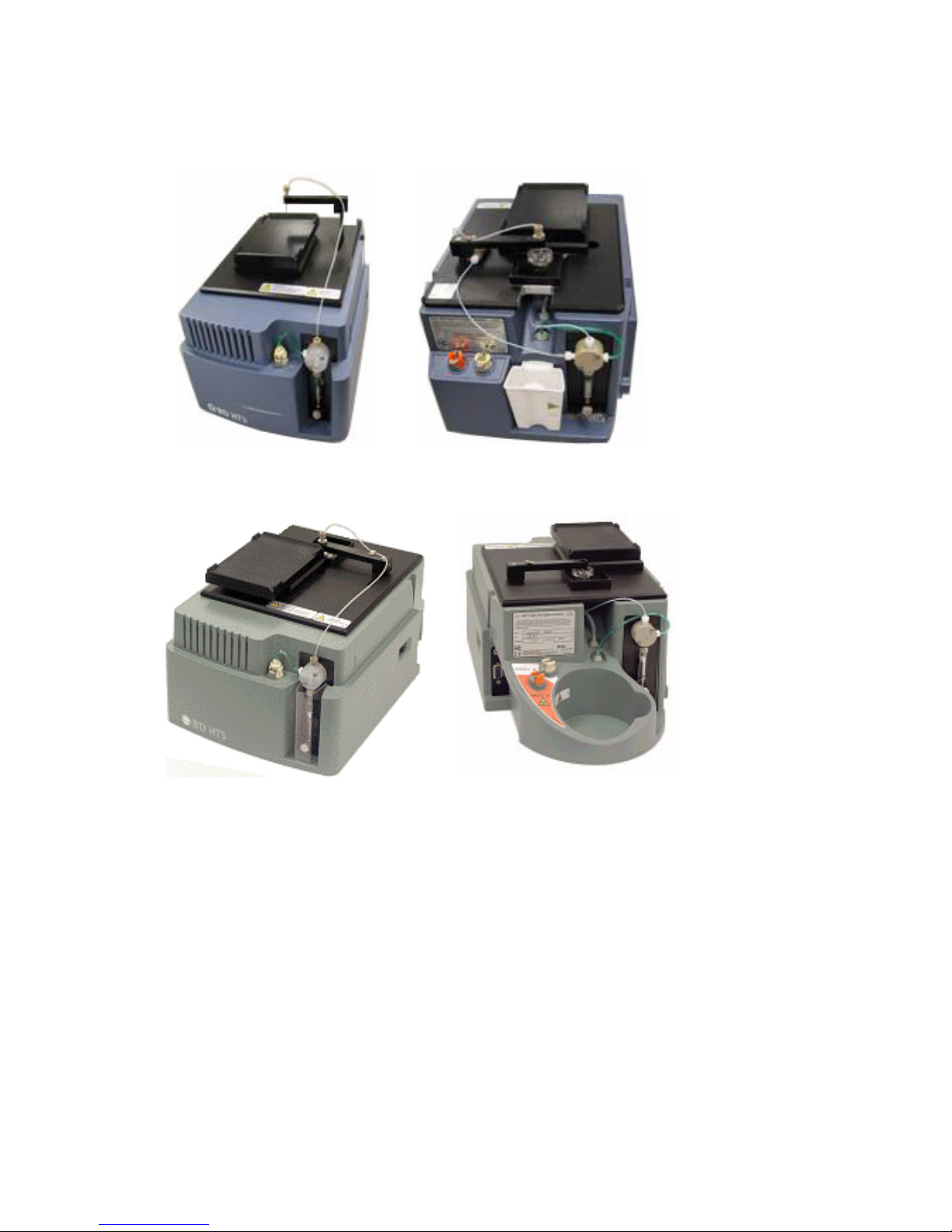
Figure 1-1 HTS for the BD FACSCanto II system
Note: The module
body color for the
BD FACSCanto is
blue
Figure 1-2 HTS for the BD FACSCalibur and BD FACSCanto systems
4 HTS Customer Care Kits User’s Guide
Page 11
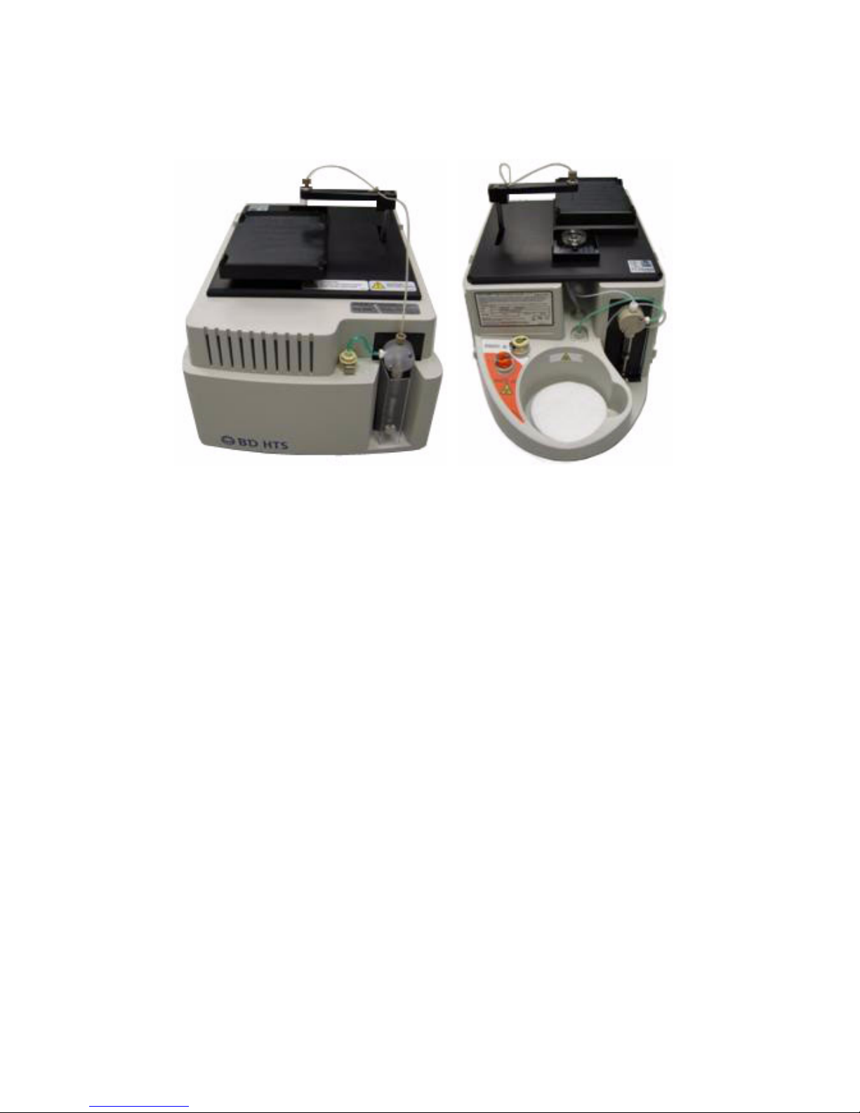
Figure 1-3 HTS for the BD LSR II, special order BD LSR II and BD LSRFortessa systems
Note: The
module body
color might be
unique to your
system.
NOTE The main HTS module shown is the same for all BD LSR products. The
BD LSRFortessa analyzer has an extra protective cover that mounts to the
original BD LSR II HTS cover.
Location of Commonly Clogged Components
The clogs that occur and need repair are in the fluidics system. The following
schematic identifies the most commonly clogged components. The numbers refer
to component parts in the Required Kit Components tables throughout this
guide.
Chapter 1: Overview of HTS Customer Care 5
Page 12
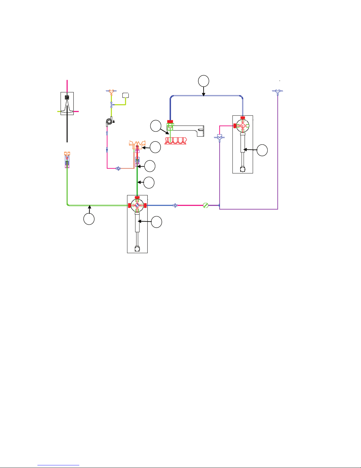
Figure 1-4 Schematic of the HTS fluidics system
Pressure
Flow cell
SIT
switch
Waste
pump
Wash station
12
Probe
1
Tray
2
3
4
Primary
pump
6
Valve
5a
6
HTS
pump
6 HTS Customer Care Kits User’s Guide
Page 13
Safety and General Precautions
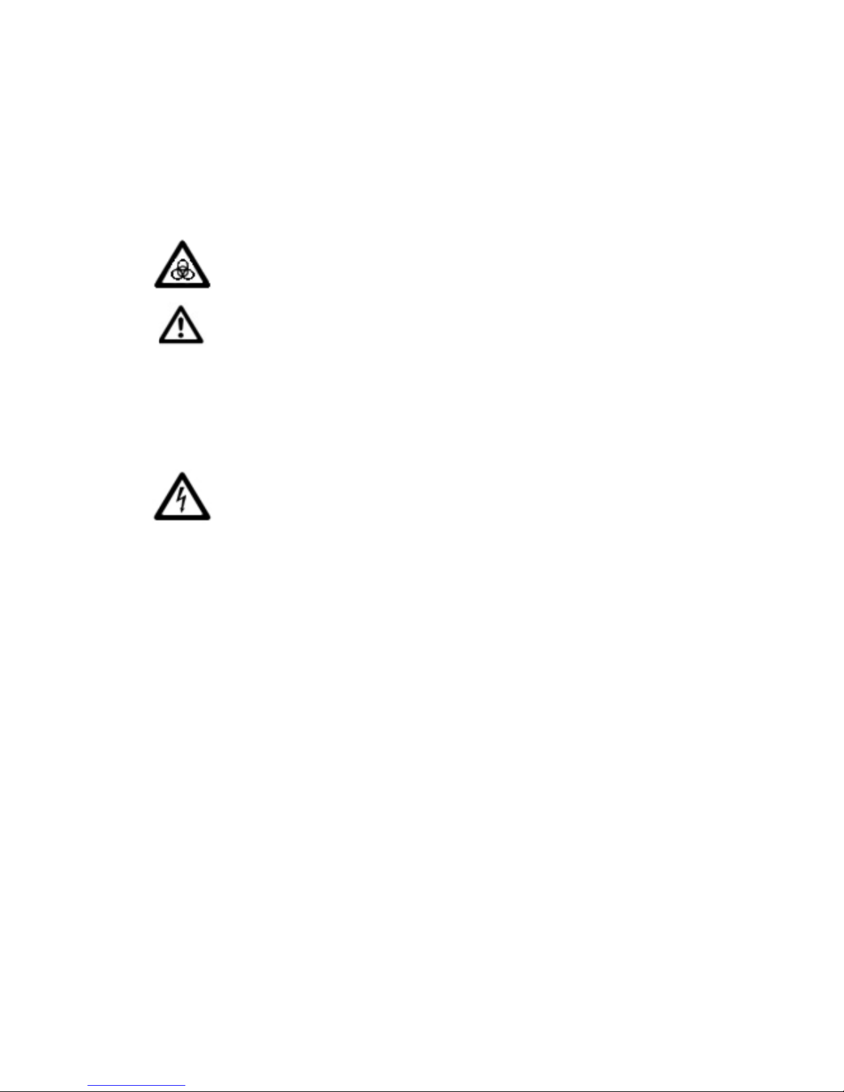
Biological Safety
All instrument surfaces that come in contact with biological specimens
can transmit potentially fatal disease.
Use universal safety precautions when changing tubing or removing any
part in contact with the fluidics system.
Wear suitable protective clothing, eyewear, and gloves.
Electrical Safety
Ensure that the power to the HTS is turned off before handling
electrical cables and their connections.
Precautions
1 Tighten all fittings finger tight. Do not use tools to further tighten
connectors.
2 If a connector is difficult to remove because of saline deposits, clean with
deionized (DI) water, then carefully use the 5/16 wrench in the accessory kit
to remove the connector.
3 The sealing washers in the valves of each port can be compressed, and will
eventually block the port. To avoid compression, tighten fittings until they
make contact with the sealing washer and then turn the fitting an
additional 1/6 to 1/4 turn. If there is a leak, tighten the fitting no more than
an additional 1/8 turn.
Chapter 1: Overview of HTS Customer Care 7
Page 14

THIS PAGE INTENTIONALLY LEFT BLANK
Page 15

2
HTS Removal and Reinstallation
Before performing replacement procedures, remove the HTS from the cytometer.
Pay particular attention to the following:
• Always disconnect electrical connections (interlock cable and interface
cable) and fluidic connections (waste, sheath, and sample injection tubing
(SIT)).
• The waste and sheath fittings on the back side of the HTS can easily be
broken when moving the HTS away from the cytometer while these fittings
are connected. Move the HTS just enough (approximately 2 inches) to
provide the room necessary to disconnect the waste and sheath fittings
from the HTS.
All instrument surfaces that come in contact with biological specimens
can transmit potentially fatal disease.
BD FACSCanto II System
Removing the HTS
1 Turn off the cytometer and HTS.
2 Remove or open the BD High Throughput Sampler safety cover.
Chapter 2: HTS Removal and Reinstallation 9
Page 16

3 Detach the sample coupler from the cytometer SIT.
a Unscrew the top nut.
b Pull the sample coupler down and away from the SIT, leaving the nut
attached to the sample coupler.
4 Unscrew the captive screw located at the bottom of the HTS support
bracket.
5 Pull the HTS out (about 2 inches) from the support bracket.
6 Remove the probe and the overflow reservoir.
7 Disconnect interlock and interface cables.
8 Disconnect the sheath and waste connectors from the HTS.
9 Disconnect the sampler coupler from the cytometer SIT.
10 Disconnect the door sensor cable.
a Lift the front feet of the HTS just over the front edge of the enclosure
and tilt the unit at a 45° angle toward you for access to the door sensor
cable on the right side.
b Unplug the door sensor cable by pulling back on the ferrule.
c Place the cable over the right side of the enclosure/carrier.
10 HTS Customer Care Kits User’s Guide
Page 17
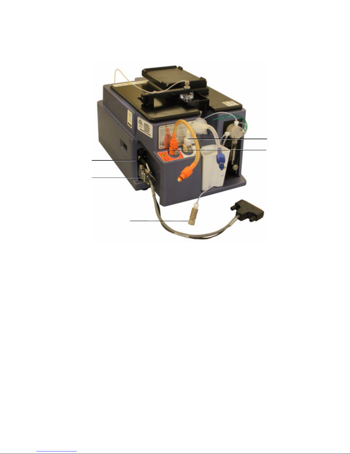
11 Place the HTS unit on a stable work bench.
Waste tubing
connection
Interlock cable
connection
Sampler coupler
Sheath tubing
connection
Interface cable
connection
Reinstalling the HTS
1 Place HTS on support bracket.
2 Connect the interlock cable to the HTS.
3 Connect the interface cable to the HTS.
4 Connect the waste tubing to the waste connector on the HTS.
5 Connect the sheath tubing to the sheath connector on the HTS.
6 Connect the sampler coupler to the SIT on the cytometer.
Chapter 2: HTS Removal and Reinstallation 11
Page 18

7 Tighten the captive screw that secures the HTS to the support bracket.
8 Turn on the cytometer.
BD FACSCanto, BD LSR II, BD FACSCalibur, and BD
LSRFortessa Systems
Removing the HTS
1 Turn off the cytometer and HTS.
2 Remove the HTS cover.
3 Unscrew the captive screw located at the bottom of the HTS support
bracket.
NOTE There is no captive screw in BD LSRFortessa, because the HTS is
placed on a sliding drawer.
4 Pull the HTS out (about 2 inches) from the support bracket.
5 Remove the probe and the overflow reservoir.
6 Disconnect the power cable and the serial communications cable.
7 Disconnect the sampler coupler from the cytometer SIT.
8 Disconnect the sheath and waste connectors from the cytometer.
9 Remove the HTS from the support bracket.
a Support the HTS on its base, raise the back of the HTS to balance the
load, and lift it off the support bracket.
10 Place the unit on a stable work beach and replace the necessary part.
12 HTS Customer Care Kits User’s Guide
Page 19
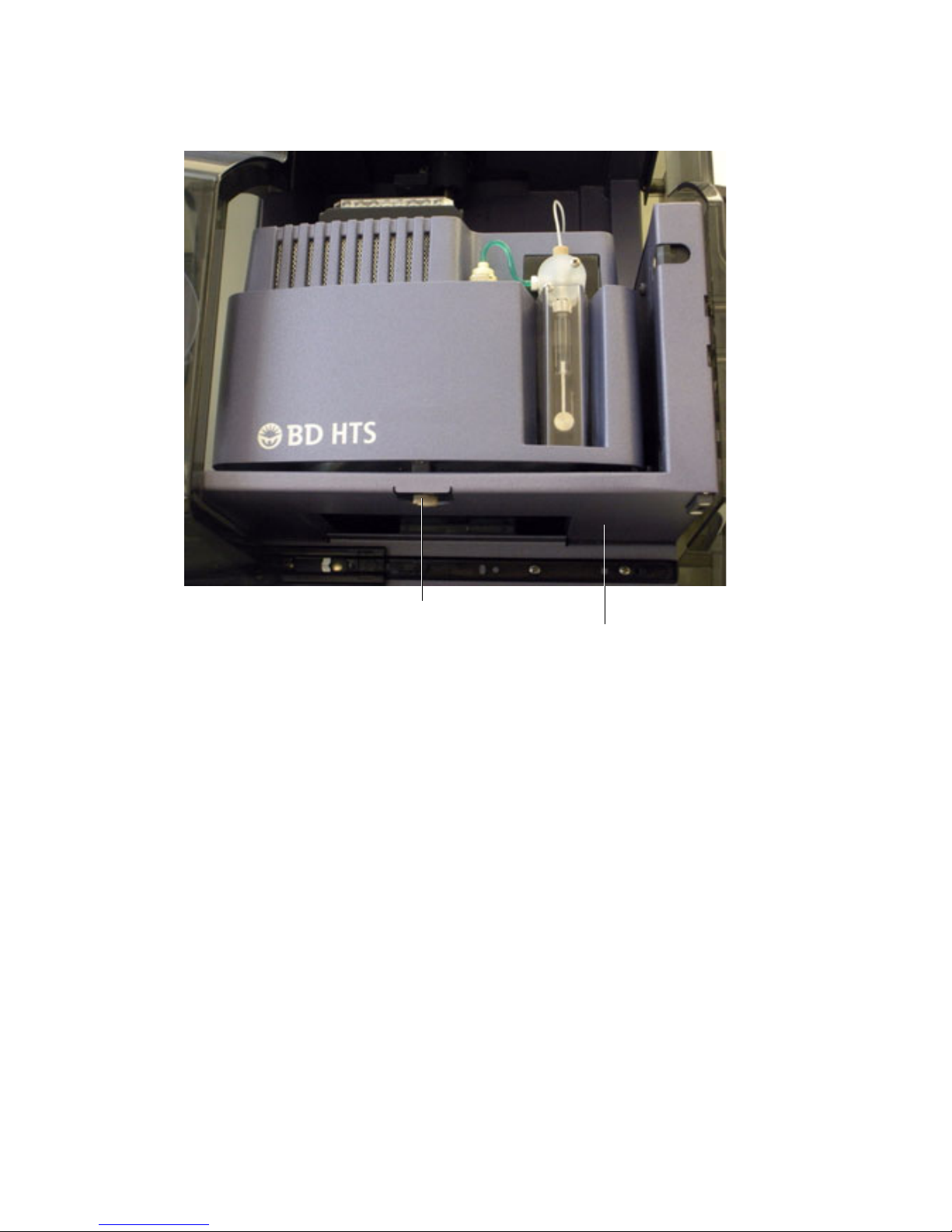
Captive screw
HTS positioned on its support bracket
Chapter 2: HTS Removal and Reinstallation 13
Page 20
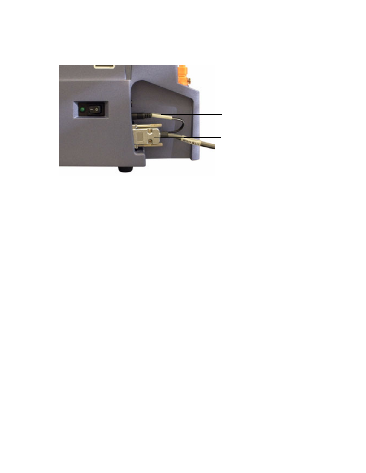
Figure 2-1 Electrical connection to the HTS
Power plug
Serial cable
14 HTS Customer Care Kits User’s Guide
Page 21
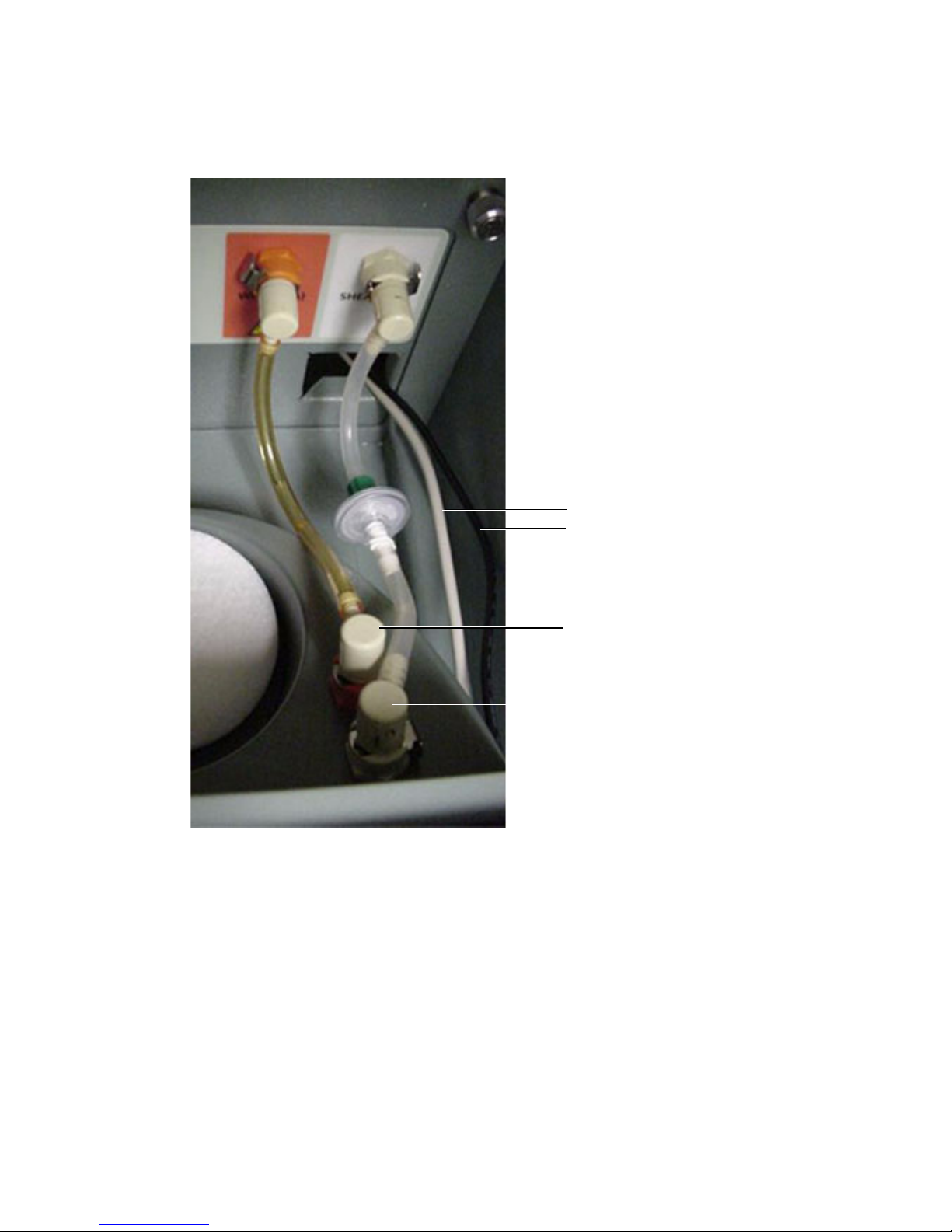
Figure 2-2 Fluidic connections to HTS
Routing of power and
communication cables
Sheath fluid connection
Waste fluidic connection
Reinstalling the HTS
1 Place the HTS on the support bracket.
2 Reconnect the power cable and the serial communications cable.
3 Reconnect the sheath and waste connectors to the HTS.
Chapter 2: HTS Removal and Reinstallation 15
Page 22

4 Slide the HTS unit as far as it can go.
5 Secure the mounting screw to the bottom on the HTS.
6 Place the cover back on the HTS and turn it on.
7 Attach the sample coupler to the SIT.
8 Turn on the cytometer.
9 Start BD FACSDiva™ software or Plate manager software if connected to
the BD FACS Calibur and perform an HTS prime.
16 HTS Customer Care Kits User’s Guide
Page 23

3
Wash Station Assembly
Replacement
Perform the wash station assembly maintenance tasks every six months or when
the following symptoms occur:
• The HTS exhibits higher than normal carryover between samples
• The wash station overflows
Required Kit Components
The sample injection tubing (3) connects the injection port/wash station (1) to the
secondary pump valve (not shown).
Item
number
1 336947 Injection port/wash station 1
2 335526 Tubing, injection port 1
3 335451 Tubing assembly, sample injection tubing to
Part
Number
Description Qty
1
HTS pump
Chapter 3: Wash Station Assembly Replacement 17
Page 24
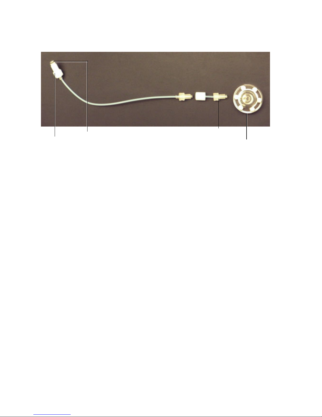
Replacing Wash Station Components
Injection port/wash station
Injection port tubing
Sampler coupler
Sealing washer
1 Perform the monthly cleaning procedure to decontaminate the sample
injection port/wash station. For instructions, see your BD High
Throughput Sampler User’s Guide.
2 Turn off the cytometer and HTS if needed.
3 Remove the HTS according to procedure in Chapter 2.
4 Move the probe arm up and toward the front of the HTS.
5 Unscrew and remove the sample injection tubing from the top of the
secondary pump.
18 HTS Customer Care Kits User’s Guide
Page 25
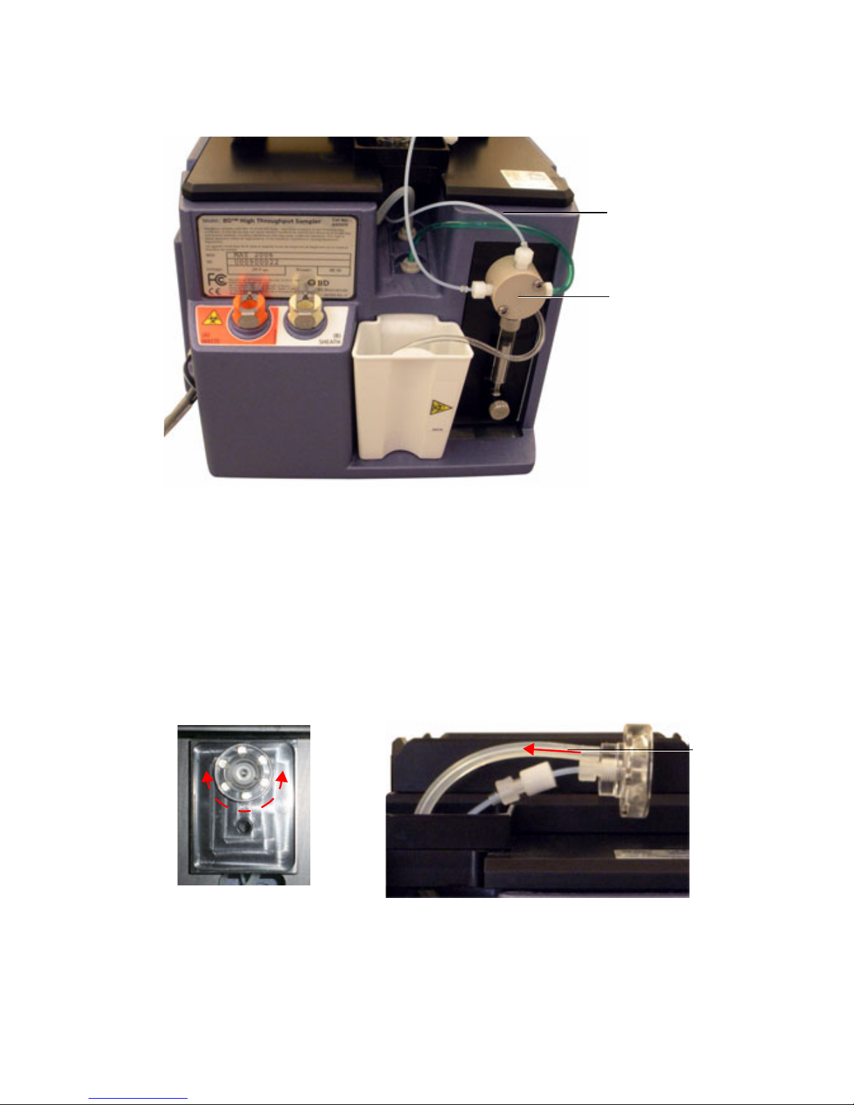
The tubing nuts are normally finger tight. If it is difficult to unscrew a
Tubing assembly
Secondary pump
Silicon
tubing
tubing nut, use a 5/16 wrench to loosen it.
6 Turn the sample injection port (see figure) slightly to disengage the
magnets, and lift the port approximately 1 inch.
7 Disconnect the silicon tubing from the sample injection port. Do not
disconnect the silicon tubing at the lower end because this could damage
the lower connector.
.
Chapter 3: Wash Station Assembly Replacement 19
Page 26
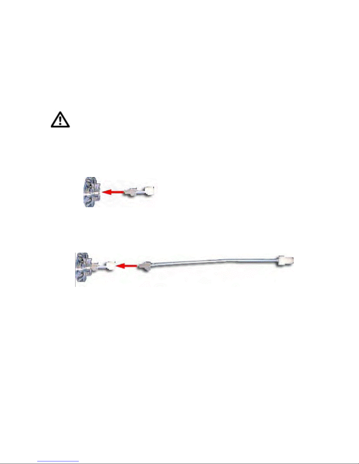
8 Secure the silicon tubing so that it does not slide back into the hole, and
carefully remove the sample injection port assembly.
Assembling the Sample Injection Tubing Assembly
To prevent the cross-threading of fittings, ensure that mating fittings are
aligned to one another before screwing them together. All fittings should be
secured only finger tight and not beyond.
1 Connect the sample injection port to the sample injection port tubing
assembly.
2 Connect the injection port tubing assembly to the sample injection tubing
assembly.
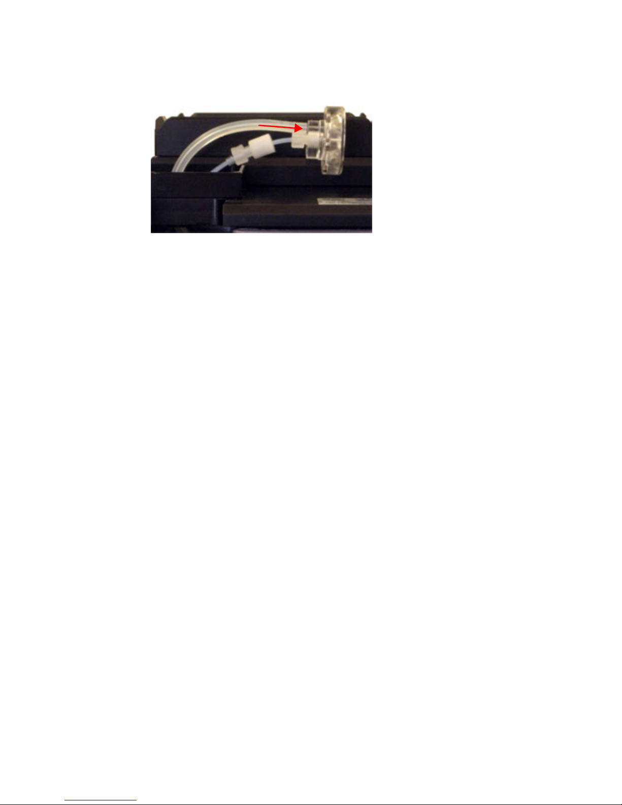
3 Lower the sample injection port tubing assembly into the port hole and
connect the silicon tubing to the sample injection port base (as shown in the
following figure). The magnets will secure the sample injection port in
place.
20 HTS Customer Care Kits User’s Guide
Page 27
4 Install and tighten the sample injection tubing assembly to the top of the
secondary pump and install the HTS on the cytometer (see Chapter 2).
Chapter 3: Wash Station Assembly Replacement 21
Page 28

THIS PAGE INTENTIONALLY LEFT BLANK
Page 29

4
Tubing Assembly Replacement
Perform the tubing assembly from probe to the primary pump maintenance tasks
when the following symptoms occur:
• Tubing is clogged
• The systems displays a primary pump (Pump-1) error
• No events are detected
Required Kit Components
Item
number
4 335454 Tubing assembly, sample probe to the
Part Number Description Qty
primary pump
1
Chapter 4: Tubing Assembly Replacement 23
Page 30
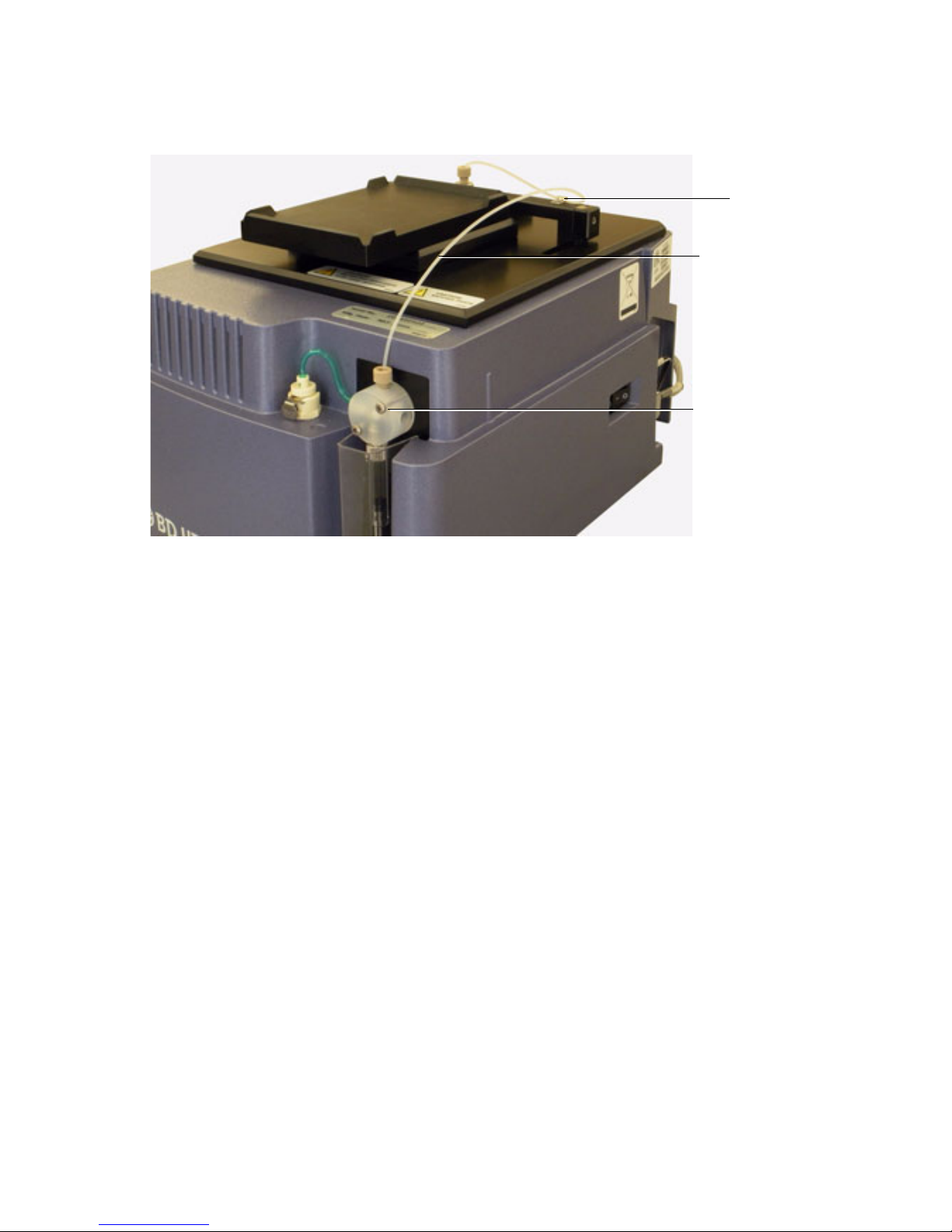
NOTE Use caution when handling the sample injection port assembly. This
Clamp
Primary pump
Tubing assembly
assembly is fragile and can be easily damaged.
Replacing Tubing Assembly Components
1 Turn off the cytometer and HTS and move the sample probe into the
sample injection port.
2 Remove the sample probe tubing assembly.
3 Unscrew the sample injection tubing from the probe and the top of primary
pump.
The sample injection tubing connectors are indicated in the following
figure.
24 HTS Customer Care Kits User’s Guide
Page 31
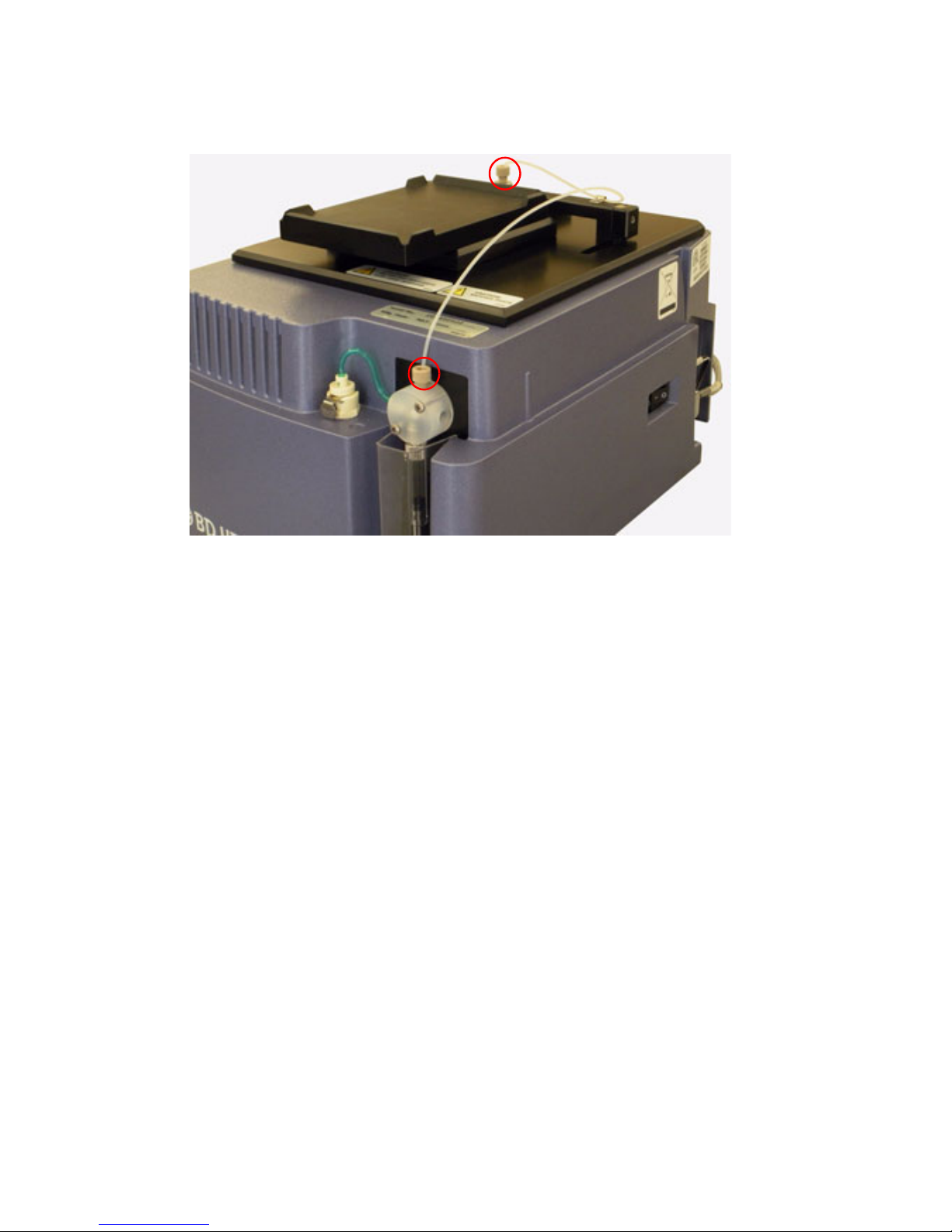
4 Remove the sample probe tubing by rotating the tubing clamp on the arm
to allow enough clearance for the tubing to be removed. If a connector is
difficult to remove due to saline deposits, clean it with DI water. If it still
does not unscrew, then carefully use the 5/16 wrench and gently loosen the
clamp. Do not force.
5 Connect the sample probe tubing.
NOTE Valves contain sealing washers in each port. If you over-tighten the
fitting, the sealing washers can be compressed, resulting in a blocked port.
Tighten the fitting until it contacts the sealing washer, and then turn the
fitting an additional 1/6 to 1/4 turn. If leaking is observed, tighten the
fitting no more than an additional 1/8 turn.
6 Install the sample probe tubing in the clamp on the arm and rotate the
clamp back into position.
7 Install and tighten the sample injection tubing to the sample probe and to
the top of the primary pump.
8 Turn on the cytometer and perform a Prime.
Chapter 4: Tubing Assembly Replacement 25
Page 32

THIS PAGE INTENTIONALLY LEFT BLANK
Page 33

5
Sample Coupler and Tubing
Replacement
The sample coupler is frequently installed or removed from the SIT to run the
cytometer in tube acquisition mode. The sample coupler tubing is attached to the
HTS secondary pump.
Replace the sample coupler tubing annually or when the following symptoms
occur:
• The system displays a secondary pump (Pump-2) error
• The sample coupler continues to leak after being tightened
A rare symptom can be no events are detected.
Chapter 5: Sample Coupler and Tubing Replacement 27
Page 34
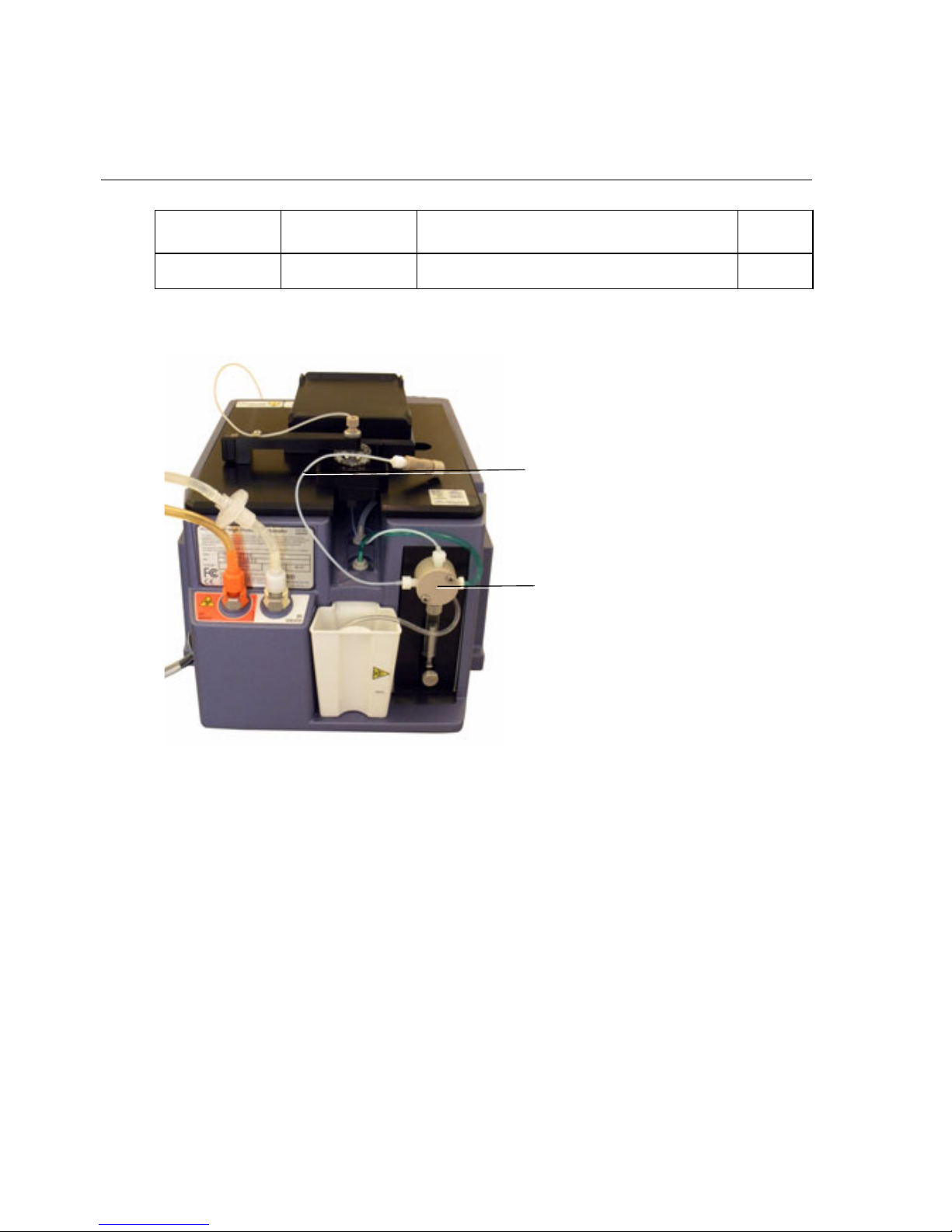
BD FACSCanto and FACSCanto II Systems
Sample coupler, secondary pump to SIT
Secondary pump
Item number Part number Description Qty
5 339340 Sample coupler, secondary pump to SIT 1
Figure 5-1 Sample coupler and tubing for the BD FACSCanto and BD FACSCanto II systems
1 Turn off the cytometer, and remove the HTS from the cytometer (see
Chapter 2).
2 Unscrew the sample coupler tubing from the left port of secondary pump
valve (indicated in the figure) and discard the sample coupler with tubing
into a biohazardous waste container.
28 HTS Customer Care Kits User’s Guide
Page 35
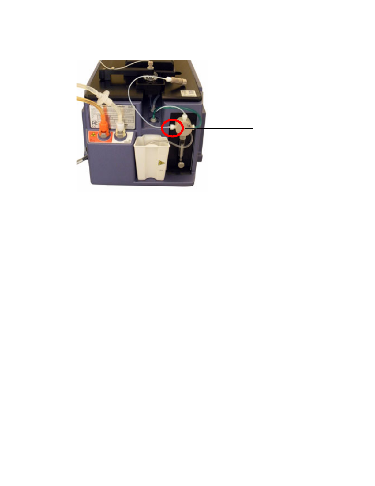
3 Install the new sample coupler tubing provided in the HTS Customer Care
Secondary pump valve
Kit.
4 Connect the new tubing to the left port in the secondary pump valve, and
tighten the tubing until the fitting is finger tight.
NOTE Valves contain sealing washers in each port. If you over-tighten the
fitting, the sealing washers can be compressed, resulting in a blocked port.
Tighten the fitting until it contacts the sealing washer, and then turn the
fitting an additional 1/6 to 1/4 turn. If leaking is observed, tighten the
fitting no more than an additional 1/8 turn.
5 Install the HTS on the cytometer (see Chapter 2).
Chapter 5: Sample Coupler and Tubing Replacement 29
Page 36
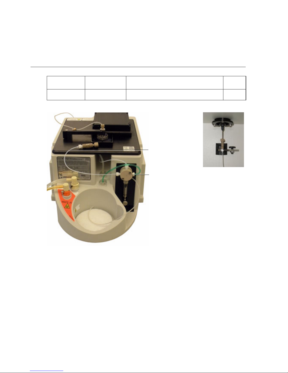
BD FACSCalibur, BD LSR II, or BD LSRFortessa
Secondary pump
Sample coupler, secondary
pump to SIT
Systems
Item number Part number Description Qty
5a 335452 Sample coupler, secondary pump to SIT 1
1 Fill a small, clean container with approximately 300 mL of DI water.
2 Remove the sheath line from the HTS.
3 Connect the purge tubing to HTS sheath port (see Chapter 9).
30 HTS Customer Care Kits User’s Guide
Page 37
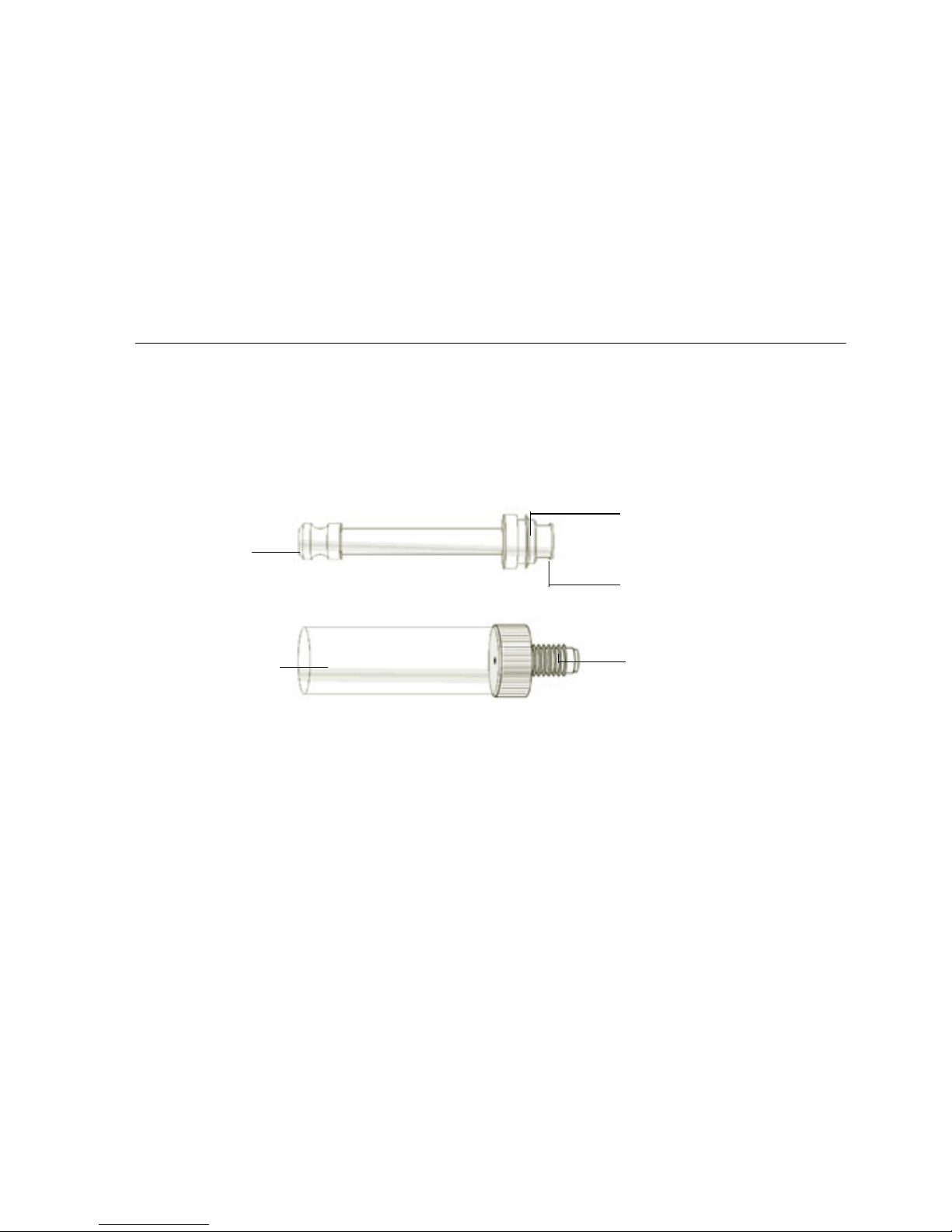
6
Syringe
Syringe barrel
Sharp raised edge
Narrow up
1/4 - 28 thread
Pump Syringe Replacement
Glass syringes are used in the primary and secondary pumps of the HTS unit. For
reference, the syringe associated with the secondary pump is shown the following
figure.
Perform the replacement of the pump syringe maintenance tasks annually or
when the following symptoms occur:
• Primary or secondary pump (Pump-1 or Pump-2) errors occur
• A Pump syringe has a clog
NOTE It is not necessary to remove the HTS when replacing the primary pump
syringe (located on the front of the HTS). However, it is necessary to remove the
HTS when replacing the secondary pump syringe (located on the rear of the
HTS).
Chapter 6: Pump Syringe Replacement 31
Page 38

Required Kit Components
Item number Part number Description Qty
6 344912 Syringe, 500 µL, with black plunger seal 1
7 347306 Lubricant, O-ring, Super O-Lube, ½-
ounce tube
1
Pump Syringe Replacement Procedures
• If you are replacing the primary pump, use both procedures in this chapter.
• If you are replacing the secondary pump, remove the HTS (see Chapter 2),
then use the Replacing the Syringe procedures.
Removing Liquid from the Syringe (For Primary Pump Syringe)
1 Verify that the cytometer and BD FACSDiva software are running.
2 From the Acquisition Dashboard select RUN PLATE.
3 Remove the liquid from the syringe:
a Disconnect the sheath connector from the back of the HTS.
b Disconnect one end of the sheath filter.
c Select HTS > Prime.
d Repeat until the syringe barrel is empty.
e Exit BD FACSDiva software.
4 Turn off the cytometer.
32 HTS Customer Care Kits User’s Guide
Page 39
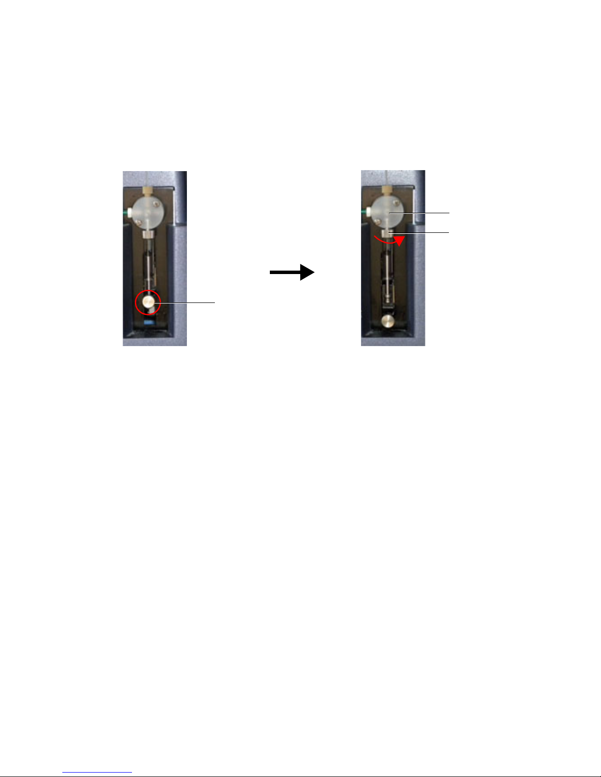
Replacing the Syringe
Plunger lock screw
Valve
Syringe barrel
1 Loosen the plunger lock screw (indicated in the following figure)
approximately three full turns.
2 Lower the plunger drive by pushing the plunger lock screw down.
3 Unscrew the syringe barrel and remove it from the lower part of the valve.
Grasp the metal ring at the top of the syringe and turn counterclockwise.
4 Discard the used syringe into a biohazard sharps container.
5 Install the new syringe:
a Screw the syringe barrel onto the valve until it contacts the seal washer,
then turn the syringe an additional 1/6 to 1/4 turn. If you observe a
leak, tighten a maximum of an additional 1/8 turn.
b Pull the syringe plunger down to the plunger holder (see the following
figure).
Chapter 6: Pump Syringe Replacement 33
Page 40
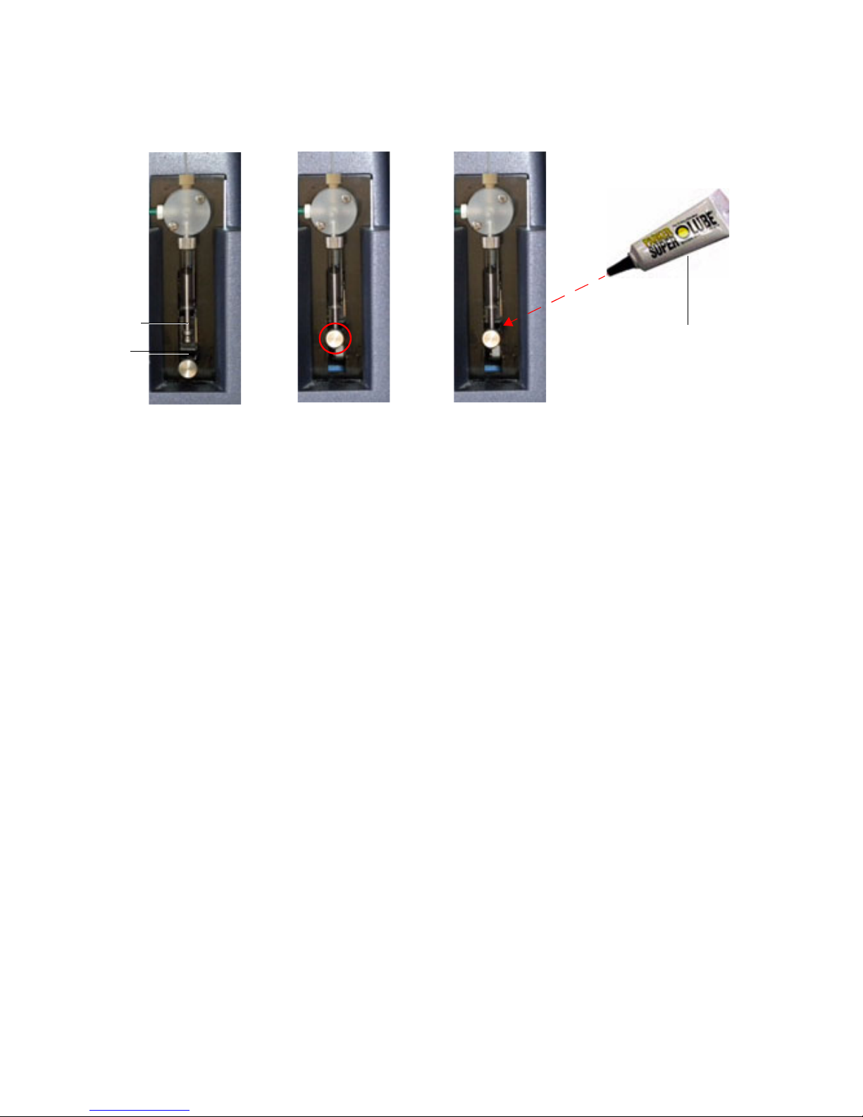
c Tighten the plunger lock screw, making sure it is securely tightened.
Lubricant
Plunger
Plunger
holder
6 Apply a generous amount of O-ring lubricant to the plunger lock screw to
prevent seizing in the future. You can apply the lubricant in the lock lever
hole before placing the plunger in it. This will help keep the saline out of
the whole assembly Do not lubricate the syringe barrel.
7 For the secondary syringe, reinstall the HTS on the cytometer (see
Chapter 2).
34 HTS Customer Care Kits User’s Guide
Page 41
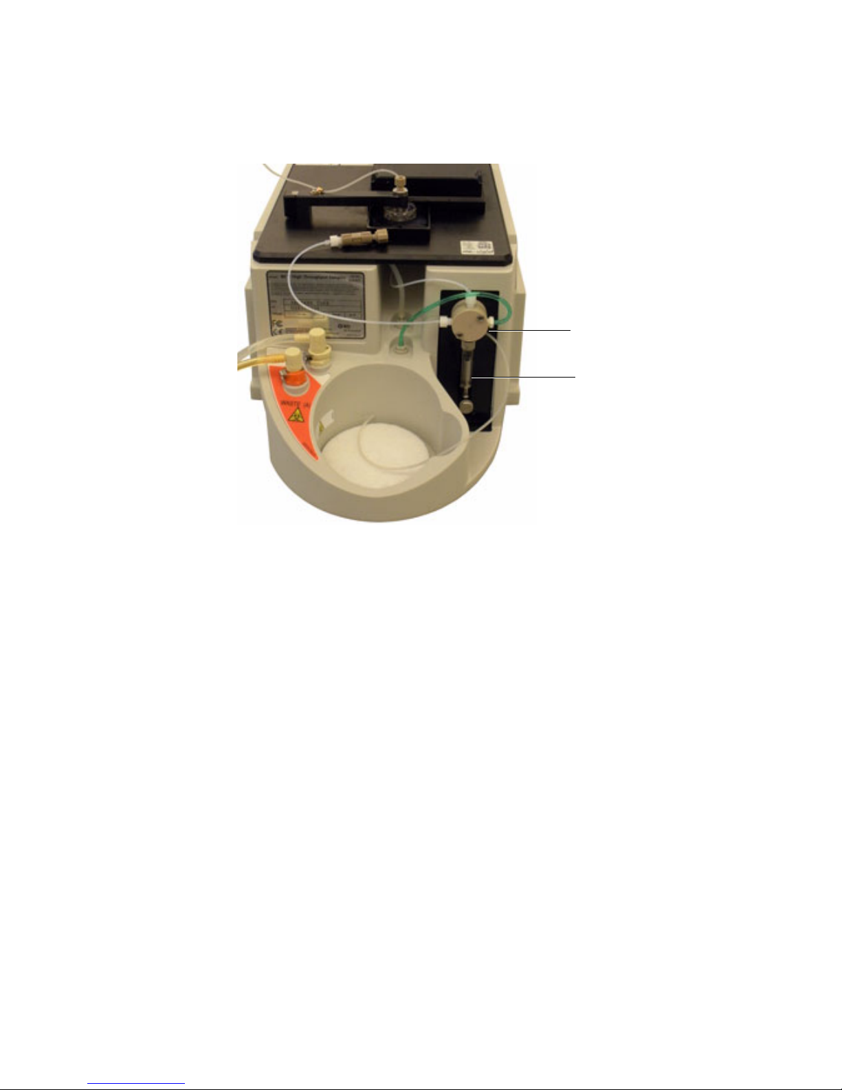
8 Turn on the cytometer and using the BD FACSDiva software, perform a
Secondary pump
Syringe
Prime.
Chapter 6: Pump Syringe Replacement 35
Page 42

THIS PAGE INTENTIONALLY LEFT BLANK
Page 43

7
Fluidic Connection and In-line
Fluidic Filter Replacement
This chapter covers the replacement of the two fluidic connections between the
cytometer and the HTS. These two fluidic connections are sheath and waste
connections.
Perform the fluidic connections maintenance and replace the sheath filter:
• Every six months
• When the sheath flow is reduced or inadequate
Chapter 7: Fluidic Connection and In-line Fluidic Filter Replacement 37
Page 44
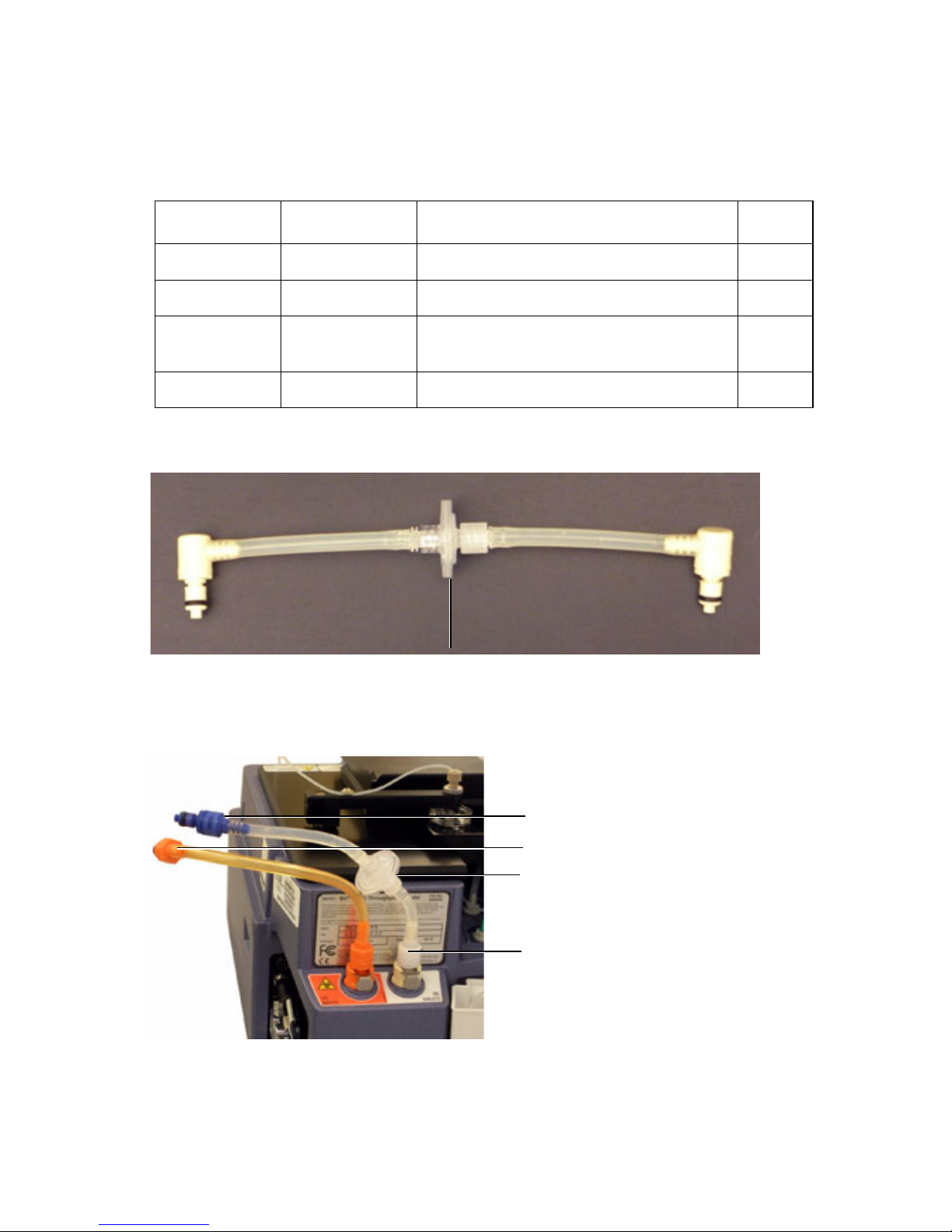
Required Kit Components
Filter
Blue hose barb
Orange hose barb
Filter
White hose barb
Item number Part number Description Qty
8 335710 Filter, 25 mm, 17-µm screen 1
9 343527 Coupling insert, hose barb (blue) 1
10 59-10090-05 Coupling insert, hose barb (orange)
(waste)
11 343529 Coupling insert, hose barb (white) 1
Figure 7-1 Filter
Figure 7-2 BD FACSCanto II connectors
1
38 HTS Customer Care Kits User’s Guide
Page 45
Replacing the Filters
1 Turn off and remove the HTS from the cytometer (see Chapter 2).
2 Replace the two liquid connections between the cytometer and the HTS:
a Move the HTS away from the cytometer to provide access behind the
HTS.
b Disconnect the quick-connector at the cytometer interface panel and
the back of the HTS (orange quick-connector end in Canto II).
c Disconnect the quick-connector at the cytometer interface panel and at
the white quick-connector on the back of the HTS unit (blue quickconnector end in Canto II).
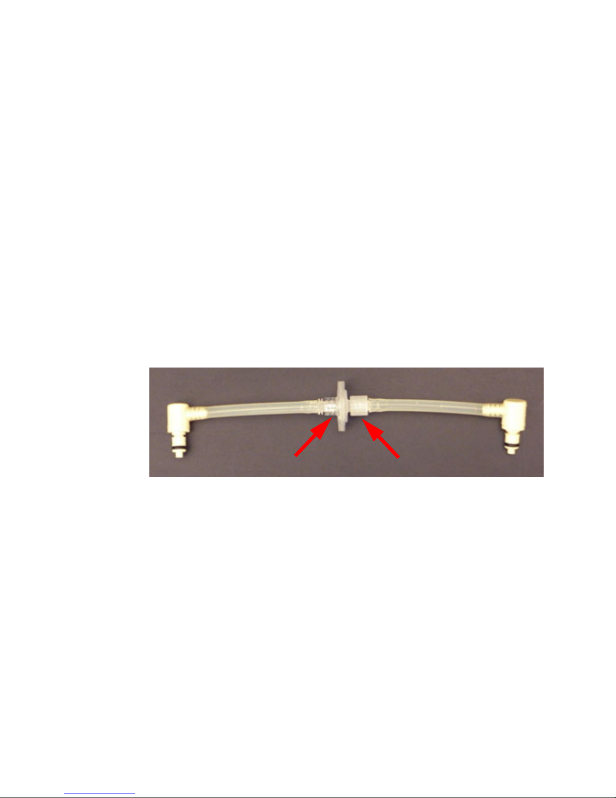
d Remove the tubing from the filter by twisting the Luer connections.
.
e Install the sheath line with the lock-ring end toward the cytometer
panel.
This will prevent foreign material that accumulates on one side of the
filter from flushing into the HTS if the filter is reversed.
3 Replace the filter and reconnect all tubing.
4 Install the HTS on the cytometer (see Chapter 2).
Chapter 7: Fluidic Connection and In-line Fluidic Filter Replacement 39
Page 46

THIS PAGE INTENTIONALLY LEFT BLANK
Page 47

Probe and Probe Tubing/Body
Assembly Replacement
The probe is located at the end of the probe assembly arm.
Replace the probe along with the probe tubing or body assembly annually, or
when the following occurs:
• Probe is bent or is not taking up sample
• Probe is clogged
8
Required Kit Components
Item number Part number Description Qty
12 34389017 Probe tubing/body assembly 1
NOTE A spare probe is included in the HTS accessory kit.
Chapter 8: Probe and Probe Tubing/Body Assembly Replacement 41
Page 48
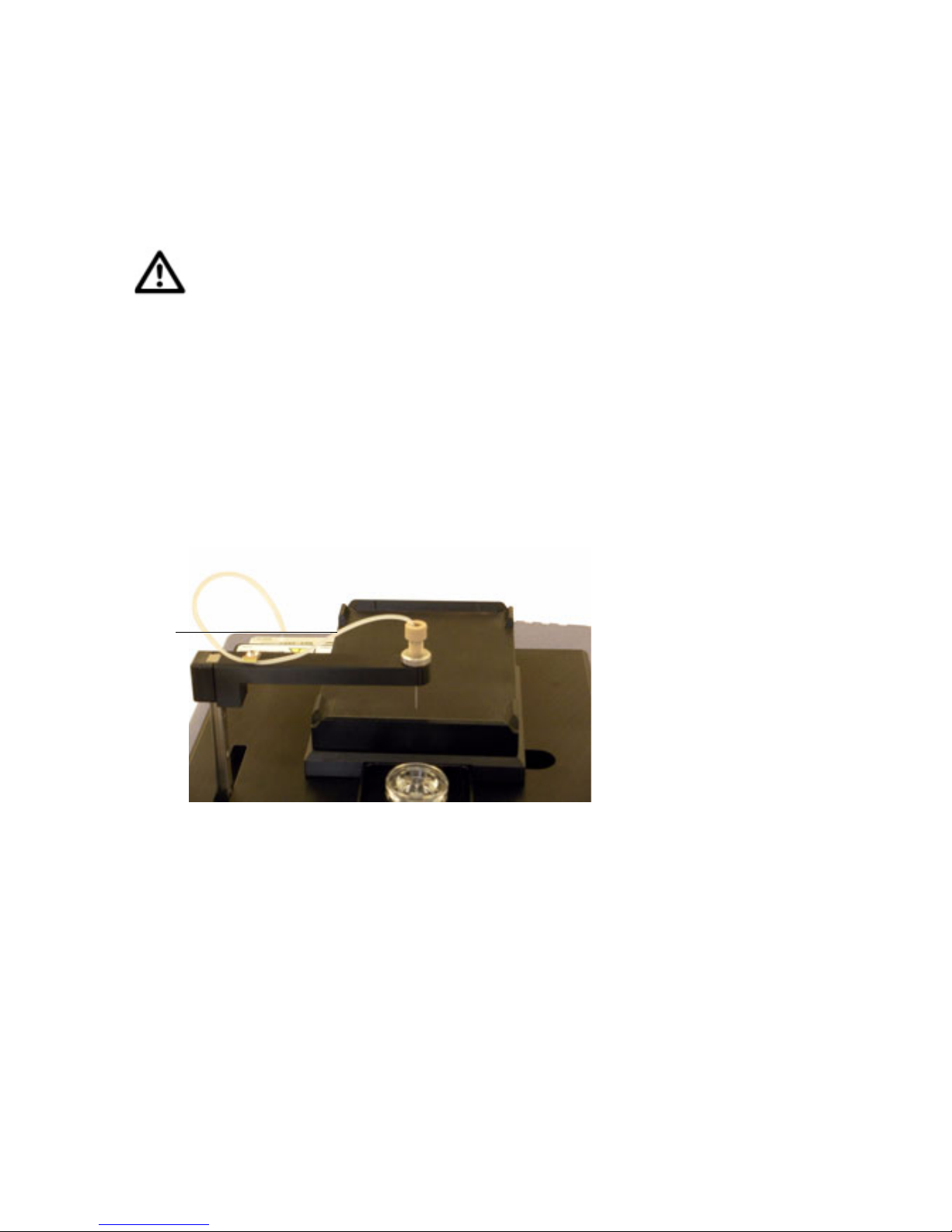
Replacing the Probe and Probe Tubing/Body
Probe
tubing/body
assembly
Assembly
The sample injection port is fragile and can be easily damaged. Use care
when handling the sample injection port.
1 Turn off the cytometer and remove the HTS cover.
NOTE On the BD FACSCanto, BD LSR II, and BD FACS Calibur systems,
you will need to turn off the power on the cytometer and the HTS
separately.
2 Pull the HTS arm up slowly and move it toward the front of the
instrument.
42 HTS Customer Care Kits User’s Guide
Page 49
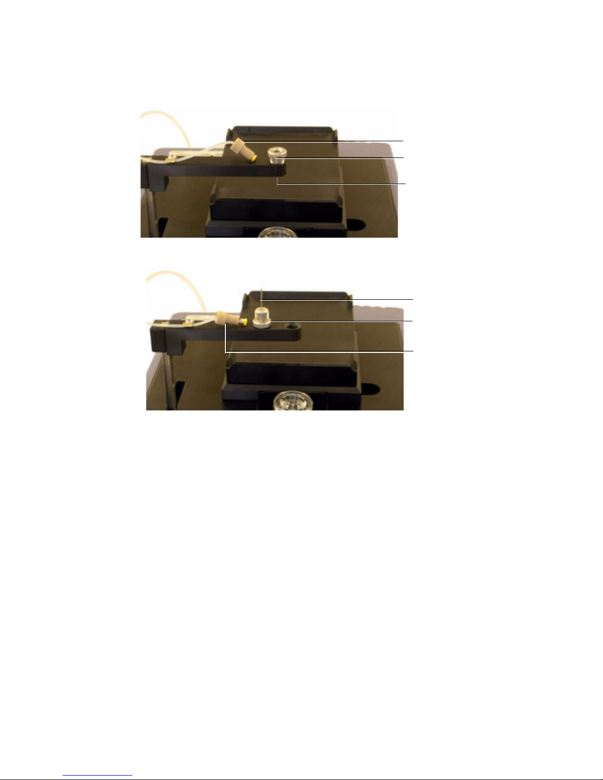
3 Unscrew the tubing connector from the probe.
Tubing connector
Probe
Probe nut
Tubing connector
Probe
Probe nut
4 Unscrew the probe nut and remove the probe from the arm.
5 Install and tighten a new probe.
a Tighten the probe nut at the top of the probe and attach the tubing
connector to the probe.
6 Turn on the cytometer and HTS if needed.
7 Start BD FACSDiva software and perform an HTS prime.
Chapter 8: Probe and Probe Tubing/Body Assembly Replacement 43
Page 50

THIS PAGE INTENTIONALLY LEFT BLANK
Page 51

9
Cleaning/Shutdown Procedure
The BD FACSCalibur, BD LSR II, and BD LSRFortessa do not have a Fluidic
Shutdown cycle that automatically replaces BD FACS™ sheath solution with BD
FACS shutdown solution or DI water. These procedures are for the BD
FACSCalibur, BD LSR II, Special Order BD LSR II, and Special Order BD
LSRFortessa systems as they do not have a fluidic shutdown cycle built into the
software.
We recommend daily cleaning and maintenance of the sample coupler and tubing
to avoid clogs.
Required Kit Components
Item number Part number Description Qty
13 340088 HTS purge tubing 1
Cleaning Procedures
1 Fill a clean container with approximately 300 mL of deionized (DI) water.
2 Remove the sheath line from the HTS.
3 Connect the purge tubing to the HTS sheath port.
Chapter 9: Cleaning/Shutdown Procedure 45
Page 52
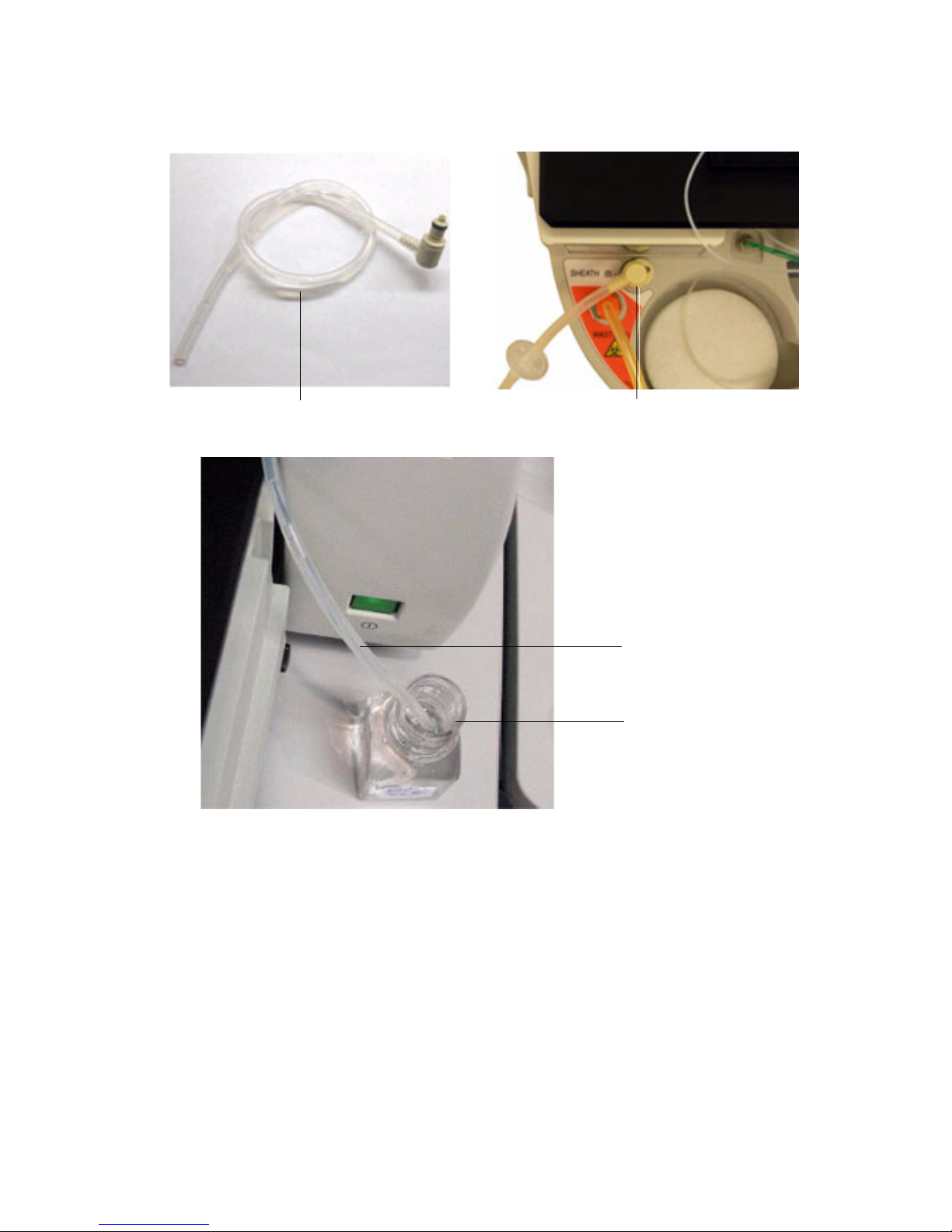
4 Submerge the other end of the purge line into the DI water.
BD HTS sheath port
HTS purge tubing
DI water
Purge tubing
5 Using BD FACSDiva software, perform a system prime. Repeat 3 times.
For BD FACS Calibur, use BD Plate Manager software to run the prime.
6 Remove the purge tubing.
7 Reinstall the sheath line.
46 HTS Customer Care Kits User’s Guide
 Loading...