


SQ594 Mainboard
User‘s Manual

User Notice
Static Electricity Precaution
Static electricity can easily damage your SQ594 mainboard. By
observing a few basic precautions can help safeguard against damage
that could result in expensive repairs. Follow the simple measures
below to protect your equipment from static electricity damage:
Keep the mainboard and other system components in their anti-static
packaging until you are ready to install them.
Touch a grounded surface before you remove any system component
from its protective anti-static packaging. Unpacking and installation
should be done on a grounded, anti-static mat. The operator should be
wearing an anti-static wristband, grounded at the same points as the
anti-static mat.
After removing the mainboard from its original packaging, only place it
on a grounded, anti-static surface component side up. Immediately
inspect the board for damage. Due to shifting during shipping, it is
suggested that the installer press down on all of the socket ICs to
ensure they are properly seated. Do this only with the board placed on
a firm flat surface.
During configuration and installation touch a grounded surface
frequently to discharge any static electrical charge that may have built
up in your body. The best precaution is to wear a grounded wrist strap.
When handling the mainboard or an adapter card avoid touching its
components. Handle the mainboard and adapter cards either by the
edges or by the adapter card case mounting bracket.

The information presented in this publication has been carefully
screened for reliability.
The manufacturer provides this manual “As is” with no warranties of
any kind, either express or implied, including, but not limited to, the
implied warranties or conditions of this product fitness for any
particular purpose. In no event shall manufacturer be liable for any loss
of profits, loss of business, loss of data, interruption of business, or
indirect, special, incidental, or consequential damages of any kind, even
if manufacturer has been advised of the possibility of such damages
arising from any defect or error in this manual or product. The
manufacturer has the right to change this specification without prenotice.
Trademarks and product names appearing in this manual are may or
may not be registered of their respective holders.


SQ594
Table of Contents
1 INTRODUCTION.......................................................................................... 1-1
1.1 HOW TO USE THIS MANUAL......................................................................... 1-1
1.2 ITEM CHECKLIST........................................................................................1-1
2 KEY FEATURES.......................................................................................... 2-1
2.1 MAINBOARD LAYOUT.................................................................................2-2
3 INSTALLATION........................................................................................... 3-1
3.1 INSTALLATION PREVIEW.............................................................................3-1
3.2 JUMPERS:................................ ...................................................................3-1
3.3 EXPANSION SLOTS:.....................................................................................3-1
3.4 CONNECTORS............................................................................................. 3-1
3.5 INSTALLATION STEPS..................................................................................3-2
4 BIOS SETUP................................ .................................................................. 4-1
4.1 ENTERING SETUP........................................................................................4-1
4.2 CONTROL KEYS..........................................................................................4-1
4.3 THE MAIN MENU........................................................................................4-3
4.4 STANDARD CMOS SETUP MENU.................................................................4-5
4.5 BIOS FEATURES SETUP MENU.................................................................... 4-8
4.6 CHIPSET FEATURES SETUP MENU.............................................................. 4-11
4.7 POWER MANAGEMENT SETUP MENU......................................................... 4-12
4.8 PCI CONFIGURATION SETUP MENU........................................................... 4-14
4.9 INTEGRATED PERIPHERALS MENU.............................................................. 4-15
4.10 PASSWORD SETTING ............................................................................... 4-17
4.11 IDE HDD AUTO DETECTION.................................................................. 4-18
1


SQ594
Introduction
How to use this Manual
This manual provides information necessary for SQ594 mainboard and is organized into 4
chapters. Its purpose is to explain the installation procedures and operations of the
mainboard as specified below.
Introduction : Manual information and checklist
Key Features : An overview of the specifications of this
mainboard
Installation : Instructions on how to setup the mainboard
BIOS setup : BIOS software setup information
Item Checklist
The SQ594 mainboard should contain followings tick( ). Immediately, contact to your
retailer if you discover any missing items, or any damage .
The SQ594 mainboard
This SQ594 user‘s manual
2 serial port ribbon cables attached to a mounting bracket
1 parallel ribbon cable attached to a mounting bracket
1 IDE ribbon cable
1 Floppy ribbon cable
PS/2 mouse cable with mounting bracket (optional )
Infrared module(optional)
USB(2-port) cable with mounting bracket(optional)
1


SQ594
key Features
Processor: The SQ594 supports Intel Pentium Processors P54C/P55C, AMD-K5 and
Cyrix 6x86 Processors. The ZIF Socket 7 will support future Pentium Overdrives.
L2 Cache: Standard package includes 256KB cache onboard. (512KB optional)
System memory: Supports four 72-pin SIMM modules using 4MB, 8MB, 16MB, or
32MB for a maximum 128MB. Memory supported is both Fast Page Mode (FPM) and
Extended Data Output (EDO). The memory must be 70ns (nano seconds) or faster.
Synchronous DRAM (SDRAM) memory DIMM Modules: Two 168-pin DIMM
memory modules are also featured on the SQ594 in addition to the four 72-pin SIMM
modules. The DIMM module sizes can be 1Mx64, 2Mx64, or 4Mx64. The DIMM
modules can be 3.3 or 5 volts and can be Fast Page Mode, EDO DRAM or 3.3V
Synchronous DRAM (SDRAM) . The memory must be 60ns or faster. The SQ594 can
support both SIMMs and DIMMs.
Intel Chipset: Intel 82430VX PCIset as the core Chipset with a Winbond 83877F/AF
super I/O (input/output) controller chip.
Expansion Slots: Three 16-bit ISA slots, four 32-bit PCI slots. (Includes one shared)
Super Multi-I/O: Two high-speed UART compatible serial ports and one parallel
port with ECP and EPP compatibility. One FDD header supporting either 5.25“ or
3.5”(1.2, 1.44 or 2.88MB) floppy drives without requiring an external I/O card. One
fast IrDA TX/RX infrared port.
PCI Bus Master IDE Controller: Onboard PCI Bus Master IDE controller with 2
ports to support 4 IDE devices. This controller supports PIO mode 3 and 4 with a data
transfer rate up to 17MB per second. The Bus Master IDE DMA mode 2 transfer up to
22MB per second.
PCI BIOS: With Green, Plug and Play, DMI, USB functions.
Universal Serial Bus: Two standard USB headers supporting up to 48MHz and 127
peripheral devices . Optional USB cable set.
IrDA and PS/2 mouse: Fast IrDA (Infrared) or on IrDA TX/RX module for wireless
interface and PS/2 mouse connector.
1
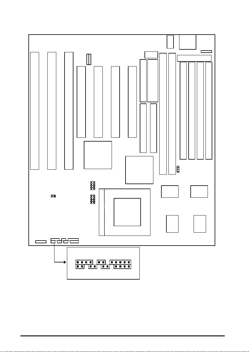
Mainboard Layout
16-bit ISA Slot 3
16-bit ISA Slot 2
16-bit ISA Slot 1
32-bit PCI Slot 4
32-bit PCI Slot 3
32-bit PCI Slot 2
32-bit PCI Slot 1
168-pin DIMM Slot 2
168-pin DIMM Slot 1
72-pin SIMM Slot 4
72-pin SIMM Slot 3
72-pin SIMM Slot 2
72-pin SIMM Slot 1
Parallel Printe
r
CON
N
COM1
Floppy Drives
Secondary IDE
Primary IDE
Powe
Conn
2
2
Mouse
LED
LE
D
IRD
A
JP1
0
JP6
JP9
JP2
JP5
1
SQ594
USB
82371SB
JP3
JP4
JP7
JP8
82437VX
ZIF Socket 7
COM2
r
.
82438VX 82438VX
JP1
KBD
PS/2
HDD LED
RESET
SUSPEND
KEYLOCK
SpeakerSuspendTurbo
64Kx3
Cache
On Board 256KB or 512KB
Pipelined Burst L2 Cache
64Kx3
Cache
2

SQ594
Installation
Installation Preview
Before you install the SQ594 mainboard into the system chassis, you may find it convenient
to first configure the mainboard hardware. This section describes how to configure the
jumper settings, install memory modules and how to attach the various system components.
Before using your computer you must review the following 6 steps:
Jumpers settings.
Installation of DRAM memory modules.
Installation of the CPU.
Installation of IDE and I/O cables and the power supply
connection.
Installation of expansion cards.
Setup of the system BIOS software.
Jumpers:
JP1 3.3V or 5V DIMM Voltage selection.
JP6 CPU 3V Voltage regulator output selection.
JP7 CPU 2V Voltage regulator output selection.
JP8, JP9 CPU V
3V/2V Voltage selection.
CORE
JP10 CMOS RAM (Operation/Clear CMOS data).
JP2, JP3 CPU external clock (Bus) frequency selection.
JP4(= BF0) CPU (Bus) frequency ratio.
JP5(= BF1) CPU (Bus) frequency ratio.
Expansion Slots:
SIMM Sockets DRAM SIMM module sockets.
DIMM Sockets SDRAM/EDO/FP DIMM module sockets.
ZIF Socket 7 Socket for Central Processing Unit (CPU).
1

SQ594
ISA Slots16-bit ISA Bus expansion slots.
PCI Slots32-bit PCI Bus expansion slots.
Connectors
Keyboard (J6)
Keybo
ard connector (5-pin).
PS/2 Mouse (J1) PS/2
Mouse Header (5-pin).
Parallel Port (J3)
Paralle
l port connector (26-pin Block).
Serial Port (J8, J9) Serial
ports COM1 & COM2 (10-pin Block).
Floppy Drive (J12) Floppy
drive connector (34-pin Block)
Power Input (J10) Power
connector (12-pin Block).
Primary IDE (J11)
Primar
y IDE connector (40-pin Block).
Secondary IDE (J13) Secondary IDE connector (40-pin Block).
USB Header (J18, J17) 2 USB ports USB1 & USB2 (5-pin).
IRDA (J29) IrDA connector (5-pin).
Key Lock (J20) Keyboard lock switch connector (5-pins).
Speaker (J21) Speaker connector (4-pin).
Suspend LED (J23)Suspend LED connector (2-pin).
Suspend Switch (J24) Suspend switch connector (2-pin).
2
SQ594
P
3
P2
P3
P1
HDD LED (J25) Hard Disk drive LED connector (4-pin).
Turbo LED (J26) Turbo LED connector (2-pin) .
Reset Switch (J28) Reset switch connector (2-pin).
WARNING: Do not apply power if the mainboard appears damaged or items are missing
from the mainboard .
Installation Steps
Jumper Settings
You can configure the hardware options by setting jumper on the mainboard. A jumper is a
set of two or more metal pins in a plastic base attached to the mainboard. A plastic “Jumper
cap” with a metal (conductive) plate inside fits over two pins to create an electrical contact
or short between them. This contact establishes a hardware setting and is referred to as a
“closed” jumper setting. Some jumpers have two pins while others may have three or more.
Jumpers are sometimes combined into sets called jumper blocks where all the jumpers in the
block must be set together to establish a hardware setting. In this manual the jumper settings
will be described as graphically using a (s)triangle always marking Pin 1. Those jumpers
with two pins will be shown as closed and open. A jumper is referred to as closed by placing
the plastic jumper cap over the two jumper pins and as open by removing the jumper cap.
Some jumpers are oriented vertically and other horizontally with Pin 1 marked as (s=P1).
Jumpers, Jumper Caps, and Jumper Blocks
Jumper cap2-pin jumper3-pin jumper
Setting 3-pin jumpers
P 1
P2
Setting 2-pin jumpers
Jumper Pins 1 & 2 are closed with a jumper cap
Jumper Pins 2 & 3 are closed with a jumper cap
This jumper is closed with the jumper cap is placed over the 2 pins
3

SQ594
This jumper is open with the jumper cap removed from the 2 pins
WARNING: Some pins are used for connectors or power sources.
These are clearly marked separately from the jumpers listed in
“Mainboard Layout”. Any improper placing of jumper caps over these
connectors will result in damage to your motherboard.
CPU Voltage Selection Jumpers (JP6, JP7, JP8, & JP9)
Intel & AMD Selection JP6 JP7 JP8 JP9`
P54C/K5
STD
(3.135-3.6V)
P54C/K5
VRE
(3.4-3.6V)
P55C
(V
=3.38V)
I/O
(V
(V
WARNING: JP8 and JP9 must always be open whether the voltage is set to 2.5V or 2.8V.
This applies to both Intel P55C CPU and the Cyrix 6x86 CPU.
CORE
(V
CORE
P55C
=3.38V)
I/O
=2.5V)
=2.8V)
Cyrix 6x86 Selection JP6 JP7 JP8 JP9`
STD
(3.15-3.6V)
VRE
(3.4-3.6V)
2.5V
(Future )
2.8V
(Future)
4

SQ594
REMARK: Effective April 24, 1996 Cyrix changed their previous part markings to their
new markings (example: 028 into 3.52V(028)) for their nominal voltage specification of
3.52 volts(also known as the VRE spec.). The table below shows Cyrix old Vs new
markings. Be sure that your mainboard voltage jumper settings are set accordingly.
Previous Marking Previous Recommended
Nominal Voltage
Blank 3.3V 3.3V or 3.52V 3.52V
016 3.3V N/A N/A
028 3.52V 3.52V(028) 3.52V
New Marking New Recommended
Nominal Voltage
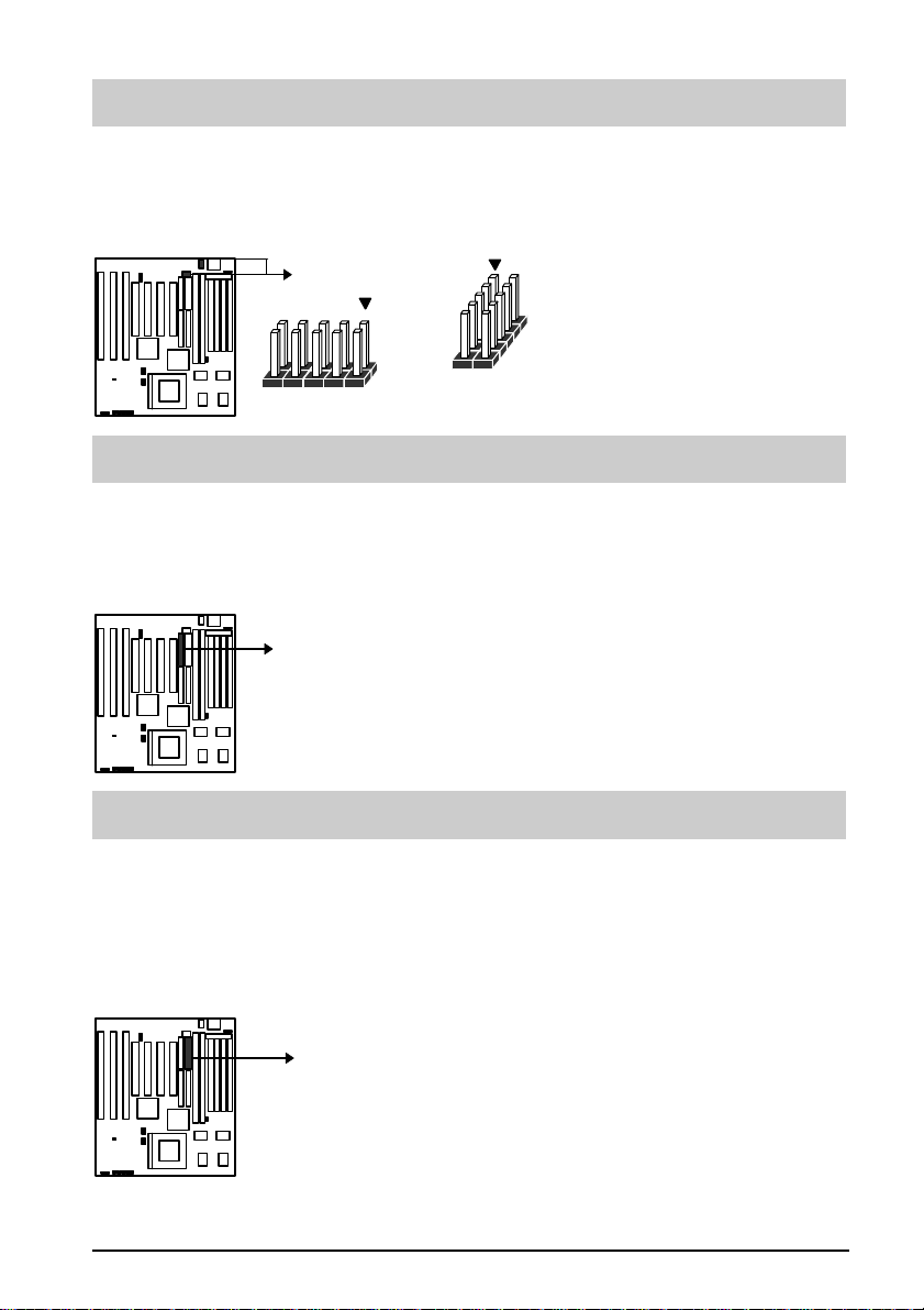
CMOS Settings(Operation/Clear CMOS Data) (JP10)
The JP10 allows you to clear the SQ594 mainboard CMOS memory and Real Time Clock
(RTC) data. The CMOS memory maintains the system configuration information and RTC
provides the system with the date and time. Make sure this jumper is open for normal
operation.
Normal (Default) Clear CMOS
Clear CMOS procedure :
To clear the stored CMOS data, do the following :
1) the system turned off, ⇒ 2) close JP10 ⇒ 3) Open JP10 ⇒ 4) ⇒ Power on ⇒ 5) Re-
setup the BIOS (refer to enter the BIOS setup menu, hold down <DEL> during the system
boot sequence).
NOTICE: Under some circumstances it is possible that the CMOS configuration settings
may be lost or corrupted causing the system to malfunction. This is not a serious problem. If
this happens, run the BIOS setup utility and re-enter your configuration settings. When you
restart the computer, the system should work normally.
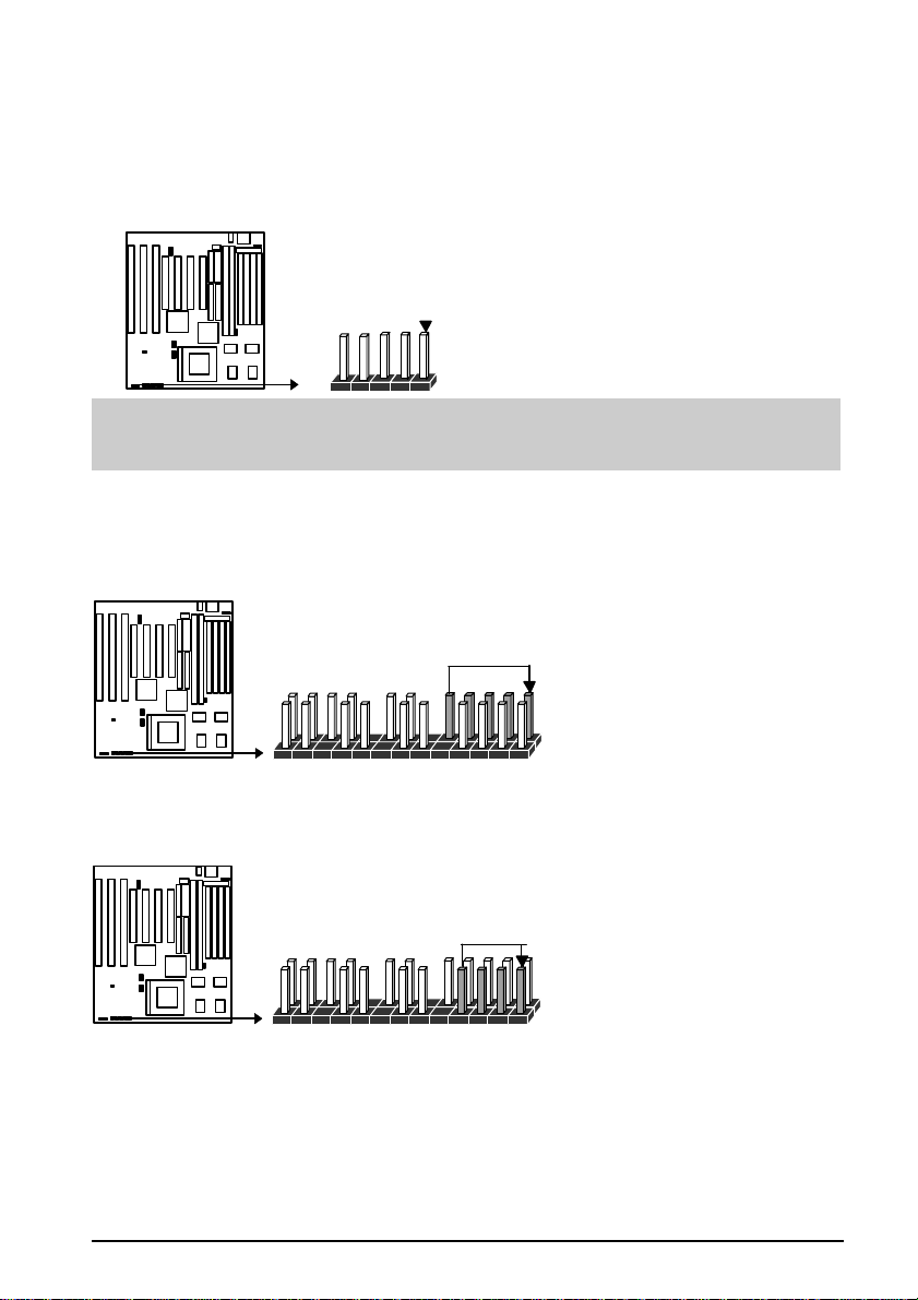
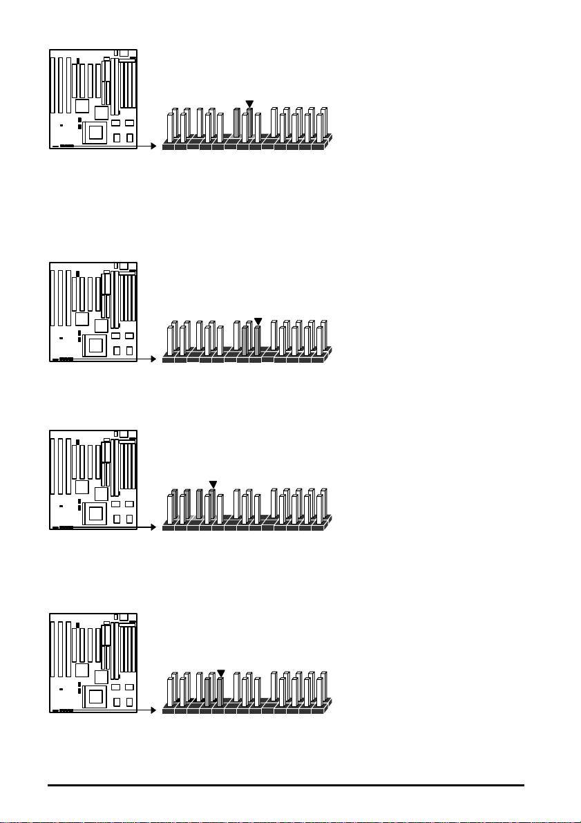
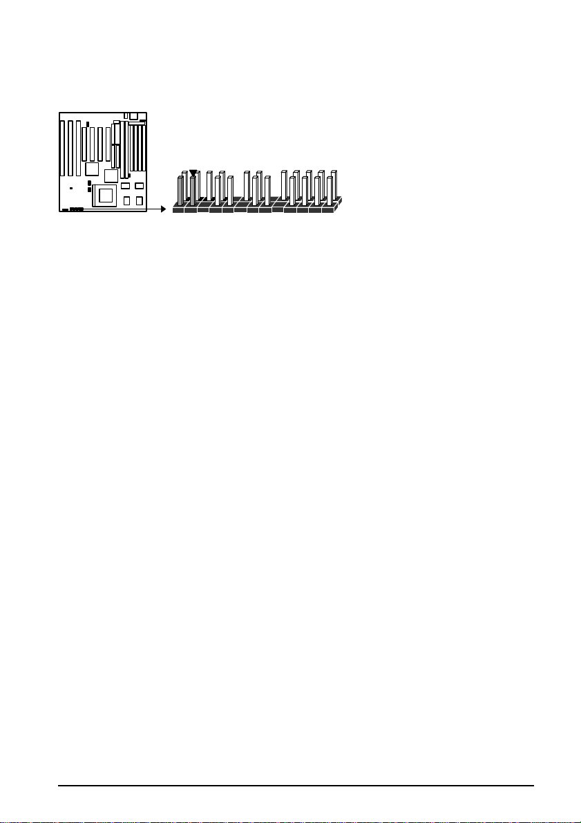
CPU Speed Selection (JP2, JP3, JP4, JP5)
The system speed depends upon the frequency of CLOCK GENERATOR which is
determined by jumpers. These jumpers tell the system what speed to run at. Currently, this
mainboard speed range is from 75MHz to 200MHz. The CPU input frequency must match
the frequency of CLOCK GEN or it will cause the system to malfunction. For example,
setting a 75MHz CPU to run at 90MHz will cause the system to malfunction.
Intel/AMD CPU Setting JP2 JP3 JP4 JP5
75MHz
5

90MHz
100MHz
120MHz
133MHz
150MHz
166MHz
180MHz
200MHz
SQ594
Cyrix 6X86 Setting JP2 JP3 JP4 JP5
100MHz(=P120+)
110MHz(=P133+)
120MHz(=P150+)
133MHz(=P166+)
NOTICE: When installing the CPU into the CPU socket, be sure that PIN 1 of the CPU is
in the same corner as the PIN 1 of socket. The CPU is an extremely sensitive electric
component and can be easily damaged by static electricity.
6

SQ594
3.3V5V
3.3
V
Expansion Slots
The SQ594 has 7 expansion Slots On-board, there are 3 16-bit ISA, and 4 32-bit PCI
expansion Slots. (Includes one share)
Installation Procedure:
To install expansion cards, please read the expansion card‘s documentation for instructions.
NOTICE: Some expansion cards require an IRQ to work and may cause a conflict. There
are a total of 16 IRQs but only 6 are free for expansion cards. In case of a conflict please
contact the system manufacturer for technical support.
1. There are two types of ISA expansion cards, design-Legacy and P-n-P (Plug & Play).
For Legacy cards you must set the card‘s jumpers manually. For Plug and Play cards,
your system will arrange the IRQs and DMAs automatically. You can verify the IRQ
allocation either by using Microsoft’s Diagnostic (MSD.EXE) utility which is in the
Windows directory or through the Windows 95 resources menu.
2. An IRQ is automatically assigned to PCI expansion cards. All of the PCI slots on the
mainboard use an interrupt. Be sure that the jumpers on your PCI cards are set to
interrupt A.
System Memory
IMPORTANT: The SQ594 System memory can support 5V Fast Page Mode or EDO
DIMM, JP1 is default set to 3.3V, please reset it to 5V location once you are using 5V
DIMM.
3.3V DIMM (Default) 5V DIMM
5 V
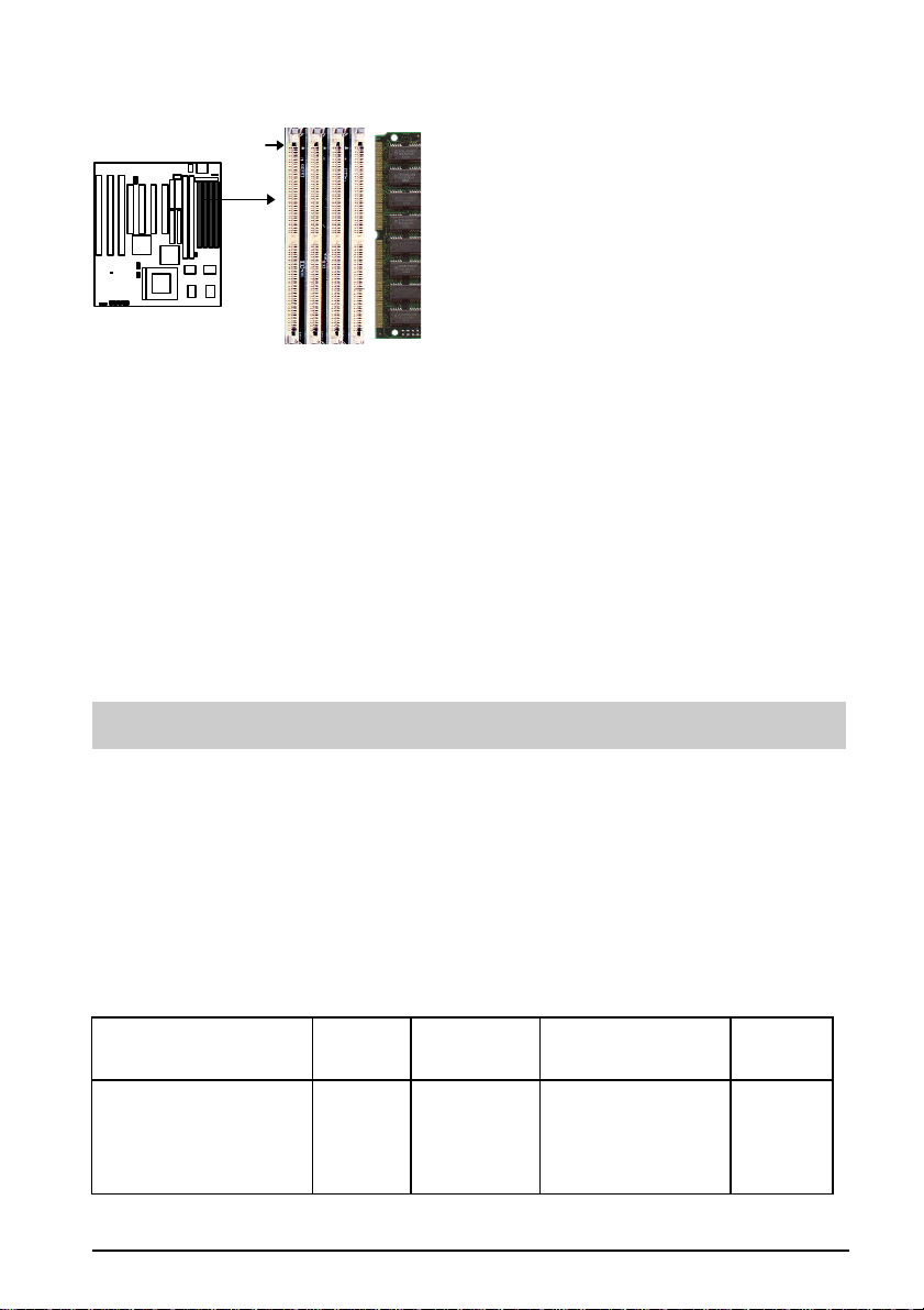
System Memory - SIMM Slots (DRAM)
You can configure the system memory size in a variety of ways by in using different
combinations of the four 72-pin DRAM SIMM modules. The memory must be 70ns (nano
seconds) or faster using either Fast Page Mode or Extended Data Output (EDO) types. The
memory chart below shows the different memory size combinations available. Please pay
attention to the following restrictions:
1) You must use one pair of sockets at a time in sequence (i.e. SIMM1 and SIMM2, or
all four sockets at once). Each pair of modules must be the same size and speed and
may be either single sided or double-sided.
2) Module sizes: Single-side SIMMs: 4MB, 16MB
3) Double-side SIMMs: 8MB, 32MB
7

SQ594
Memory Module Combinations
Total Memory (Slot 1-4) Bank 0 (Slot 1 & 2) Bank 1 (Slot 3 & 4)
8MB 4MBx2 None
16MB 8MBx2 None
32MB 16MBx2 None
64MB 32MBx2 None
8MB None 4MBx2
16MB None 8MBx2
32MB None 16MBx2
64MB None 32MBx2
16MB 4MBx2 4MBx2
24MB 4MBx2 8MBx2
40MB 4MBx2 16MBx2
72MB 4MBx2 32MBx2
24MB 8MBx2 4MBx2
32MB 8MBx2 8MBx2
48MB 8MBx2 16MBx2
80Mb 8MBx2 32MBx2
40MB 16MBx2 4MBx2
48MB 16MBx2 8MBx2
64MB 16MBx2 16MBx2
96MB 16MBx2 32MBx2
72MB 32MBx2 4MBx2
80MB 32MBx2 8MBx2
96MB 32MBx2 16MBx2
128MB 32MBx2 32MBx2
8
SQ594
Insert the SIMM Module into
Installation Procedure for System Memory
Pin 1
1. PIN1 of the SIMM module must match with the PIN1 of the SIMM socket.
2. The module will only insert into the socket one way. An orientation cut-out will
prevent you from inserting it the wrong way.
3. Insert the DRAM module into the SIMM socket at a 45 degree angle. If Pin 1 of the
SIMM does not line up with Pin 1 of the socket, the SIMM will not insert into the
socket. After inserting the SIMM module completely into socket, push the SIMM
module into a vertical position.
4. The module should click into place with the retaining clips at each end of the socket
snapping behind the module to secure it.
5. To release the memory module push both retaining clips outwards and carefully rock
the module forward.
the SIMM Socket at 45°
IMPORTANT: Do not use SIMM modules that use an extra TTL chip to convert the
memory module from asymmetric to symmetric.
System Memory - DIMM Sockets (SDRAM)
The SQ594 mainboard features two 168-pin DIMM modules with each DIMM supporting
8MB to 32MB of Synchronous DRAM using 1Mx64, 2Mx64 and 4Mx64 DIMM modules
(Asymmetrical single-and double -sided). The DRAM interfaces on a 64-bit wide data path
and supports unbuffered Fast Page Mode, Extended Data Out(EDO) 3.3V/5V DRAM 60ns
or faster. Also supported is 3.3 volts 66.67MHz unbuffered Synchronous DRAM (SDRAM).
EDO DRAM DIMM and SDRAM DIMM are defined as below:
Table 1 : EDO/FP DRAM DIMM Configurations :
Type Capacity Organization EDO DRAM
168-pin 3.3/5V
unbuffered EDO DRAM
DIMM w/ serial Presence
Detect
8MB 1Mx64
1Mx16
1 bank
(DIMM1)
Clock
Speed
60ns
9

SQ594
168-pin 3.3/5V
unbuffered EDO DRAM
DIMM w/ serial Presence
Detect
168-pin 3.3/5V
unbuffered EDO DRAM
DIMM w/ serial Presence
Detect
168-pin 3.3/5V
unbuffered EDO DRAM
DIMM w/ serial Presence
Detect
Table 2: SDRAM DIMM Configurations:
Type Capacity Organization SDRAM Clock Speed
168-pin 3.3V
unbuffered SDRAM
DIMM with serial
Presence Detect
168-pin 3.3V
unbuffered SDRAM
DIMM with serial
Presence Detect
16MB 2Mx64
16MB 2Mx64
32Mb 4Mx64
8MB 1Mx64
16MB 2Mx64
1Mx16
2 banks
(DIMM 1& 2)
2Mx8
1 bank
(DIMM 1)
2Mx8
2 banks
(DIMM1 & 2)
1Mx16
1 bank (DIMM1)
1Mx16
2 banks(DIMM 1& 2)
60ns
60ns
60ns
66.67MHz
66.67MHz
168-pin 3.3V
unbuffered SDRAM
DIMM with serial
Presence Detect
168-pin 3.3V
unbuffered SDRAM
DIMM with serial
Presence Detect
16MB 2Mx64
32Mb 4Mx64
2Mx8
66.67MHz
1 bank (DIMM 1)
2Mx8
66.67MHz
2 banks
(DIMM1 & 2)
Installation Procedure (SDRAM/EDO/FP DRAM)
1. PIN1 of the DIMM module must match with the PIN1 of the DIMM socket.
2. The module will only insert into the socket one way. An orientation cut-out will
prevent you from inserting it the wrong way.
10

SQ594
3. Insert the SDRAM module into the DIMM socket at a 90 degree angle. If Pin 1 of the
DIMM does not line up with Pin 1 of the socket, the DIMM will not insert into the
socket. After inserting the DIMM module completely into socket, push up on the
socket latches securing the DIMM into place.
4. To release the memory module push both latches down and carefully rock the module
forward.
IMPORTANT: Do not use DIMM which use an extra TTL chip to convert the memory
module from asymmetric to symmetric.
1
Insert the DIMM Module into the DIMM
Socket at 90 degree angle
Two 168-pin
DIMM
168-pin DIMM memory Module
ZIF Socket 7 for Central Processing Unit(CPU)
The SQ594 comes with a 321-pin ZIF Socket 7 for installing the CPU. The Socket 7 will
also support future Pentium up-grade processors. It is strongly recommended that a heatsink
and CPU cooling fan be used to prevent the CPU from overheating. (Tip) Applying a
thermal of jelly between the CPU and the heatsink/fan will further cool the CPU.
Installation Procedure(CPU)
To install a CPU, remember to take careful precaution against static electric discharge. The
basic procedure is as follows:
Notch
Blank Corner
IMPORTANT: you must set jumpers JP6, JP7, JP8 & JP9 to correct CPU Voltage.
1. Turn off your system and disconnect the power source.
2. Remove the existing CPU from the ZIF socket by pulling the ZIF lever upwards at a 90
-degree angle.
11
SQ594
Parallel port
3. Insert the CPU with the correct orientation as below shown. Use the notched corner of
the CPU as your guide. The notch in the corner of the CPU should correspond with
PIN1 of the ZIF socket (Notice: Pin 1 is the blank corner of the ZIF socket with one
pin hole missing).
4. Once the CPU is inserted close the socket‘s lever.
WARNING: Without a fan, the CPU can overheat and will cause damage to both the CPU
and the SQ594 motherboard.
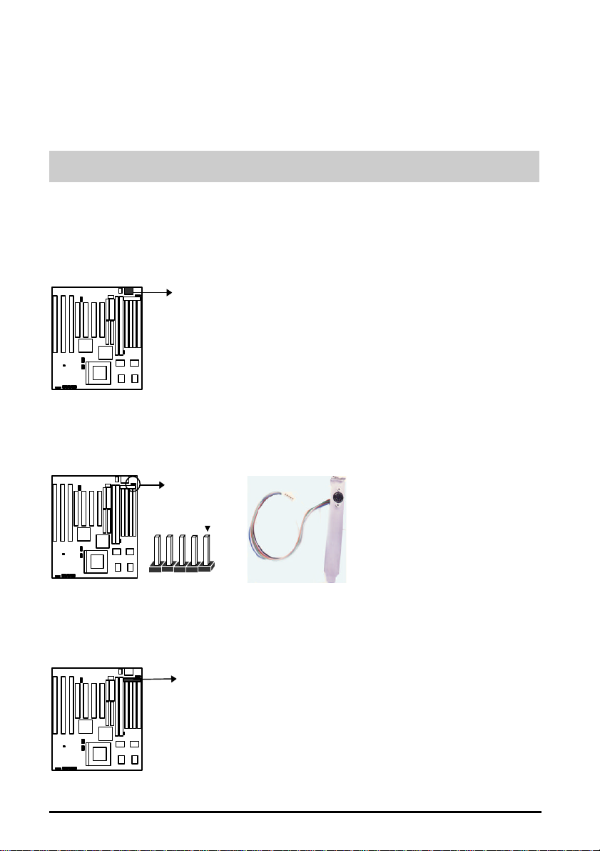
Connectors
Keyboard (J6)
This connector supports a standard 101 enhanced IBM-compatible keyboard.
Keyboard Connector
PS/2 Mouse header(J1)
This SQ594 mainboard provides a default PS/2 mouse header that supports an optional PS/2
mouse connector cable & bracket
PS2 Mouse header
PS2 Cable with Bracket
Parallel Port (J3)
This connector supports a parallel port ribbon cable and mounting bracket. Connect the
ribbon cable to this connector and mount the bracket to the back of the case.
12
SQ594
WARNING: When you connect the ribbon cable to this port, you must ensure PIN 1 of the
cable matches PIN 1 of the connector.
Serial Ports (J8, J9)
These connectors support two serial port ribbon cables (Com1& Com2). Connect the ribbon
cable to these connectors and mount the bracket to the back of the case.
Serial Ports
COM2 (J9)
COM1 (J8)
WARNING: When you connect the ribbon cable to this port, you must ensure PIN 1 of the
cable matches PIN 1 of the connector.
Floppy Driver (J12)
This connector supports the floppy drive via a floppy drive ribbon cable. The ribbon cable
can support one to two floppy drives.
Floppy Drive Connec tor
WARNING: When you connect the ribbon cable to this port, you must ensure PIN 1 of the
cable matches PIN 1 of the connector.
Power Input (J10)
This connector supports a standard power supply. Make sure that the power cord is
unplugged when you connect it. There are two power plugs, each with six colored wires. The
black wires on each plug must be placed together in the middle and then pressed into the
power connector on the mainboard.
Power
Connector
13

SQ594
Primary IDE (J11)
This connector supports two primary IDE devices via a ribbon cable. When two IDE devices
are installed using the primary IDE connector make sure that the second IDE device is
adjusted to slave mode as instructed in the device‘s manual.
WARNING: When you connect the ribbon cable to this port, you must ensure PIN 1 of the
cable matches PIN 1 of the connector.
Primary IDE Connector
Secondary IDE (J13)
This connector supports two secondary IDE devices via a ribbon cable. When two IDE
devices are installed using the secondary IDE connector make sure that the second IDE
device is adjusted to slave mode as instructed in the device‘s manual.
Secondary IDE Connector
WARNING: When you connect the ribbon cable to this port, you must ensure PIN 1 of the
cable matches PIN 1 of the connector.
Universal Serial Bus (USB) Header (J17/J18)
This SQ594 mainboard has two USB headers onboard. USB devices provide a more
convenient operating environment and improve data transferring capacity. True Plug-andPlay, this new bus technology will support over 127 different peripherals through a Hub.
WARNING: When you connect the cable to this port, you must ensure PIN 1 of the cable
matches PIN 1 of the connector.
14
USB Header
USB1 (J18)
USB2 (J17)
SQ594
IrDA connector (J29)
The SQ594 mainboard offers both Fast IrDA and IrDA functions. IrDA is the wireless
transmitting and receiving data via an optional infrared module. The efficient operating
distance is 100CM and the data transfer rates for IrDA is 1.44M KB/sec and Fast IrDA ,
4M KB/sec.
IR Co nn ect o r
IMPORTANT: You must configure this feature through the BIOS by selecting whether
UART2 is allocated for use by COM2 or for IrDA. The IR module is supported by the
mainboard via a 5-pin connector and ribbon cable.
Key Lock (5-pin ) (J20)
This connector supports the case-mounted switch for locking the keyboard for security
purposes.
Keylock Connector
Speaker (4-pin) (J21)
This connector supports the case-mounted speaker.
Speaker connector
Suspend LED (2-pin ) (J23)
This connector supports the case-mounted Green function LED.
15
SQ594
Suspend LED
Suspend Switch (2-pin)(J24)
This connector supports the case-mounted suspend switch allowing you to manually place
the system into a suspend mode or “Green” mode. During Green mode, the system activity
will be decreased to save energy when the system is not in use. If you want to use this
feature, in the Power Management Setup of the BIOS should be turn on.
Suspend Switch
Connector
HDD LED (4-pin)(J25)
This connector supports the hard disk activity indicator light on the case.
HDD LED
Turbo LED (2-pin)(J26)
This connector supports the turbo LED. It will always be on because the mainboard‘s turbo
function is always on.
Turbo LED
16
SQ594
Reset Switch (2-pin) (J28)
This connector supports the case-mounted reset. It is advised that the reset switch be used
for rebooting the system in order to extend the life of the system‘s power supply.
Reset Switch
Connector
17

SQ594
BIOS Setup
The Award's BIOS ROM has a built-in Setup program that allows users to modify the basic
system configuration. This type of information is stored in battery-backup RAM (CMOS
RAM) so that it retains the Setup information when the power is turned off.
Entering Setup
Power on the computer, the below message will appear briefly at the bottom of the screen
during the POST (Power On Self Test), press <Del> key or simultaneously press <Ctrl>,
<Alt>, and <Esc> keys.
Press DEL to enter SETUP, ESC to skip memory test
If the message disappears before you respond and you still wish to enter Setup, restart the
system to try again by turning it OFF then ON or pressing the "RESET" button on the system
case. You may also restart by simultaneously pressing <Ctrl>, <Alt>, and <Delete> keys. If
you do not press the keys at the correct time and the system does not reboot, an error
message will be displayed at the bottom of the screen and you will again be asked to,
Press F1 to continue, DEL to enter SETUP
Control Keys
<↑> , <↓>
<←> , <→>
<Esc>
<PgUp> / <+>
<PgDn> / <−>
<F1>
Shift-<F2>
<F5>
<F7>
<F10>
<F3><F4>
<F8><F9>
Move to previous or next item
Move to the item in the left or right hand
Main Menu – Quit and not save changes into CMOS
Status Page Setup Menu and Option Page Setup Menu -- Exit
current page and return to Main Menu
Increase the numeric value or make changes
Decrease the numeric value or make changes
General help, only for Status Page Setup Menu and Option Page
Setup Menu
Change color from total 16 colors. F2 to select color forward,
(Shift) F2 to select color backward
Restore the previous CMOS value from CMOS, only for Option
Page Setup Menu
Load the Setup default , only for Option Page Setup Menu
Save all the CMOS changes, only for Main Menu
Reserved
1

SQ594
Getting Help
Main Menu
The on-line description of the highlighted setup function is displayed at the bottom of the
screen.
Status Page Setup Menu/Option Page Setup Menu
Press F1 to pop up a small help window that describes the appropriate keys to use and the
possible selections for the highlighted item. To exit the Help Window press <F1> or <Esc>.
2
SQ594
ESC : Qui
t↑ ↓ → ← : Select Item
The Main Menu
Once you enter Award BIOS CMOS Setup Utility, the Main Menu (Figure 1) will appear on
the screen. The Main Menu allows you to select from ten setup functions and two exit
choices. Use arrow keys to select among the items and press <Enter> to accept or enter the
sub-menu.
ROM PCI/ISA BIOS (2A59GB3A)
CMOS SETUP UTILITY
AWARD SOFTWARE, INC.
STANDARD CMOS SETUP USER PASSWARD
BIOS FEATURE SETUP IDE HDD AUTO DETECTION
CHIPSET FEATURES SETUP
POWER MANAGEMENT SETUP
PNP/PCI CONFIGURATION SAVE & EXIT SETUP
INTEGRATED PERIPHERALS EXIT WITHOUT SAVING
LOAD SETUP DEFAULTS
F10 : Save & Exit Setup (Shift)F2 : Change Color
Time, Date Hard Disk Type…
Figure 1
Standard CMOS setup
This setup page includes all the items of standard CMOS setup features.
BIOS features setup
This setup page includes all the items of Award special enhanced features.
Chipset features setup
This setup page includes all the items of Chipset special features.
Power Management setup
This category determines how much power consumption for system after selecting.
PNP/PCI Configuration
This category specifies all the items of PCI/ISA devices’ resources configuration and
assignment.
3

SQ594
Load setup defaults
Setup defaults indicates the values required by the system for the maximum performance.
Integrated peripherals
This setup page includes all the items of peripherals I/O setup features.
User Password
Change, set, or disable password. It allows you to limit access to the system and Setup, or
just to Setup.
IDE HDD auto detection
Automatically configure hard disk parameters.
Save & exit setup
Save CMOS value changes to CMOS and exit setup.
Exit without save
Abandon all CMOS value changes and exit setup.
4

SQ594
Standard CMOS Setup Menu
The items in Standard CMOS Setup Menu are divided into 10 categories. Each category
includes no, one or more than one setup items. Use the arrow keys to highlight the item and
then use the <PgUp> or <PgDn> keys to select the value you want in each item.
ROM PCI/ISA BIOS (2A59GB3A)
STANDARD CMOS SETUP
AWARD SOFTWARE, INC.
Date (mm:dd:yy) : Sun,
Time (hh:mm:ss) :
HARD DISKS TYPE SIZE CYLS HEAD PRECOMP LANDZ SECTOR MODE
Primary Master :
Primary Slave :
Secondary Master :
Secondary Slave :
Drive A :
Drive B :
Video :
Halt On :
ESC : Quit
F1 : Help (Shift)F2 : Change Color
1.44MB, 3.5 in.
None
EGA/VGA
All Errors
May 12 19996
10 : 10 : 00
Auto
Auto
Auto
Auto
↑ ↓ → ←
0 0 0 0 0 0
0 0 0 0 0 0
0 0 0 0 0 0
0 0 0 0 0 0
Base Memory: 640K
Extended Memory: 31744K
Other Memory: 384K
Total Memory: 32768K
: Select Item PU/PD/+/- : Modify
AUTO
AUTO
AUTO
AUTO
Figure 2
Date
The date format is <day>, <date> <month> <year>. Press <F3> to show the calendar.
day The day of week, from Sun to Sat, determined by the
BIOS, is read only
date The date, from 1 to 31 (or the maximum allowed in the
month), can key in the numerical / function key
month The month, Jan through Dec.
year The year, depend on the year of BIOS
Time
The time format is <hour> <minute> <second>. which accepts both function key or
numerical key The time is calculated based on the 24-hour military-time clock. For
example, 1 p.m. is 13:00:00.
5

SQ594
Hard Disks
The categories identify the types of hard disks that have been installed in the computer.
There are 45 predefined types, 1 user definable type and 1 Auto type. The Auto Type can
auto configure your hard disks.
Primary Master/Slave and Secondary Master/Slave
There are 4 items in this categories to identify the types of 2 hard disk channel that have
been installed in the computer.
Press PgUp/<+> or PgDn/<−> to select a numbered hard disk type or type the number and
press <Enter>. Note that the specifications of your drive must match with the drive table.
The hard disk will not work properly if you enter improper information for this category. If
your hard disk drive type is not matched or listed, you can use User Type to define your own
drive type manually.
If you select User Type, related information is asked to be entered to the following items.
Enter the information directly from the keyboard and press <Enter>. This information should
be provided in the documentation from your hard disk vendor or the system manufacturer.
CYLS. number of cylinders
HEADS number of heads
PRECOMP write precom
LANDZONElanding zone
SECTORS number of sectors
MODE HDD access mode
If the controller of HDD interface is ESDI, the selection shall be “Type
1”.
If the controller of HDD interface is SCSI, the selection shall be
“None”.
If the controller of HDD interface is CD-ROM, the selection shall be
“None”.
If a hard disk has not been installed select NONE and press <Enter>.
6

SQ594
Drive A/B type
The category identifies the types of floppy disk drive A or drive B that have been installed in
the computer.
None No floppy drive installed
360K, 5.25in5-1/4 inch PC-type standard drive; 360 kilobyte
capacity
1.2M, 5.25in5-1/4 inch AT-type high-density drive; 1.2 megabyte
capacity
720K, 3.5in3-1/2 inch double-sided drive; 720 kilobyte capacity
1.44M, 3.5in3-1/2 inch double-sided drive; 1.44 megabyte
capacity
2.88M, 3.5in3-1/2 inch double-sided drive; 2.88 megabyte
capacity
Video
The category selects the type of adapter used for the primary system monitor that must match
your video display card and monitor. Although secondary monitors are supported, you do
not have to select the type in Setup.
You have two ways to boot up the system:
When VGA as primary and monochrome as secondary, the selection of the video tape is
“VGA Mode”.
When monochrome as primary and VGA as secondary, the selection of the video type is
“Monochrome mode”.
EGA/VGAEnhanced Graphics Adapter/video Graphics Array.
For EGA, VGA, SEGA, or PGA monitor adapters.
CGA 40 Color Graphics Adapter, power up in 40 column mode
CGA 80 Color Graphics Adapter, power up in 80 column mode
MONO Monochrome adapter, includes high resolution
monochrome adapters
7

SQ594
Halt on
The category determines whether the computer will stop if an error is detected during power
up.
No errors Whenever the BIOS detects a non-fatal error the
system will be stopped and you will be
prompted.
All errors The system boot will not be stopped for any
error that may be detected.
All, But
Keyboard
All, But
Diskette
All, But
Disk/Key
The system boot will not stop for a keyboard
error; it will stop for all other errors.
The system boot will not stop for a disk error; it
will stop for all other errors.
The system boot will not stop for a keyboard or
disk error; it will stop for all other errors.
Memory
The category is display-only which is determined by POST (Power On Self Test) of the
BIOS.
Base Memory
The POST of the BIOS will determine the amount of base (or conventional) memory
installed in the system. The value of the base memory is typically 512K for systems with
512K memory installed on the motherboard, or 640K for systems with 640K or more
memory installed on the motherboard.
Extended Memory
The BIOS determines how much extended memory is present during the POST. This is the
amount of memory located above 1MB in the CPU's memory address map.
Other Memory
This refers to the memory located in the 640K to 1024K address space. This is memory that
can be used for different applications. DOS uses this area to load device drivers to keep as
much base memory free for application programs. Most use for this area is Shadow RAM.
8
SQ594
Virus Warning
:
Video BIOS Shadow:
C8000-CBFFF Shadow:
External Cache:
CC000-CFFFF Shadow:
Quick Power On Self Test:
D0000-D3FFF Shadow:
Boot Sequence
:
D4000-D7FFF Shadow:
Swap Floppy Drive
:
D8000-DBFFF Shadow:
Boot Up Floppy Seek
:
D8000-DFFFF Shadow:
Boot Up Numlock Status:OnTypematic Rate Setting:
Typematic Rate (Chars/Sec):6Typematic Delay (Msec):
Security Option
:
PS/2 mouse function control
:
ESC:Qui
t↑ ↓ → ← : Select ItemPCI/VGA Palette Snoop:
F1 :Help PU/PD/+/- : ModifyOS Select For DRAM > 64MB
:
F5:Old Values(Shift)F2 : Change Color
Total Memory
System total memory is the sum of base memory, extended memory, and other memory.
BIOS Features Setup Menu
ROM PCI/ISA BIOS (2A59GB3A)
BIOS FEATURES SETUP
AWARD SOFTWARE, INC.
Disabled
Enabled
Enabled
C,A
Disabled
Enabled
Disabled
250
Setup
Disabled
Disabled
Non-OS2
F7 : Load Setup Defaults
Figure 3
Enabled
Disabled
Disabled
Disabled
Disabled
Disabled
Disabled
Virus Warning
This category flashes on the screen. During and after the system boots up, any attempt to
write to the boot sector or partition table of the hard disk drive will halt the system and the
following error message will appear, in the mean time, you can run an anti-virus program to
locate the problem.
! WARNING !
Disk boot sector is to be modified
Type "Y" to accept write or "N" to abort write
Award Software, Inc.
Enabled Activates automatically when the system boots up causing a warning
message to appear when anything attempts to access the boot sector
or hard disk partition table.
Disabled No warning message to appear when anything attempts to access the
boot sector or hard disk partition table.
Note: This function is available only for DOS and other OSes that do not trap INT13.
CPU External Cache
The default value is Enable.
9

SQ594
Quick Power On Self Test
This category speeds up Power On Self Test (POST) after you power on the computer. If it
is set to Enable, BIOS will shorten or skip some check items during POST.
Boot Sequence
This category determines which drive computer searches first for the disk operating system
(i.e., DOS).
C,A System will first search for hard disk drive then floppy
disk drive.
A,C System will first search for floppy disk drive then hard
disk drive.
CDROMSystem will boot from CDROM.
Swap Floppy Drive
This category allows you to swap two floppy disk drive for reading or writing data. When
enabled the BIOS swaps floppy disk drive assignments, so that Drive A becomes Drive B,
and Drive B becomes A.
Boot Up Floppy Seek
During POST, BIOS will determine if the floppy disk drive installed is 40 or 80 tracks.
360K type is 40 tracks while 760K, 1.2M and 1.44M are all 80 tracks.
Enabled BIOS searches for floppy disk drive to determine if it is 40
or 80 tracks. Note that BIOS can not tell from 720K,
1.2M or 1.44M drive type as they are all 80 tracks.
DisabledBIOS will not search for the type of floppy disk drive by
track number. Note that there will not be any warning
message if the drive installed is 360K.
Boot Up NumLock Status
Keypad is number keys when it is on and arrow keys when it is off.
10

SQ594
Typematic Rate Setting
Enabled Enable typematic rateand typematic delay
programming
Disabled Disable typematic rateand typematic delay programming.
The system BIOS will use default value of this 2 items
and the default is controlled by keyboard.
Typematic Rate (Chars/Sec)
It controls the speed at which the system registers repeated keystrokes. The range is from 6
to 30 characters per second.
Typematic Delay (Msec)
It controls the time between the display of the first and second characters. There are for
delay rates: 250ms, 500ms, 750ms and 1000ms.
250 250 msec
500 500 msec
750 750 msec
1000 1000 msec
Security Option
This category allows you to limit access to the system and Setup, or just to Setup.
SystemThe system will not boot and access to Setup will be
denied if the correct password is not entered at the
prompt.
Setup The system will boot, but access to Setup will be denied if
the correct password is not entered at the prompt.
Note: To disable security, select PASSWORD SETTING at Main Menu and then you will
be asked to enter password. Do not type anything and just press <Enter>, it will disable
security. Once the security is disabled, the system will boot and you can enter Setup freely.
PS/2 mouse function control
This category allows you to Enable or disable PS/2 Mouse function.
11

SQ594
Enabled Enable PS/2 mouse function
Disabled Disable PS/2 mouse function
PCI/VGA Palette Snoop
Some display cards which are non-standard VGA (such as graphics accelerators or MPEG
Video Cards) may not show colors properly. This setting enabled should fix this problem.
OS select for DRAM > 64MB
When using OS/2 operating systems with installed DRAM of greater than 64MB, you have
to enable this option.
Video BIOS Shadow
It determines whether video BIOS will be copied to RAM, however, it is optional from
Chipset design. Video Shadow will increase the video speed.
C8000 - DFFFF Shadow
These categories determine whether other expansion cards‘ ROM BIOS will be copied to
Main memory by 16K byte or 32K byte per/unit and the size depends on Chipset. Which
segment should be chose depending on cards ‘ ROM BIOS address decoding and chip’s size.
12

SQ594
DRAM Timing
:
ISA Bus Clock
:
System BIOS Cacheable
:
Video BIOS Cacheable
:
8 bit I/O Recovery Time
:116 bit I/O Recovery Time:1Memory Hole At 15M-16M:
ESC:Qui
t↑ ↓ → ← : Select ItemF1 :Help PU/PD/+/- : ModifyF5:Old Values(Shift)F2 : Color
Chipset Features Setup Menu
ROM PCI/ISA BIOS (2A59GB3A)
CHIPSET FEATURES SETUP
AWARD SOFTWARE, INC.
70ns
PCICLK/3
Disabled
Disabled
Disabled
F7 : Load Setup Defaults
Figure 4
ISA Bus Clock
Determine the clock rat of ISA bus.
System BIOS Cacheable
Define whether or not the System area to be cached by the on board cache RAM
Video BIOS Cacheable
Define whether or not the Video BIOS area to be cached by the on board cache RAM
8 Bit I/O Recovery Time
Select recovery time for 8 bit I/O
16 Bit I/O Recovery Time
Select recovery time for 16 bit I/O
Memory Hole At 15M-16M
For special old ISA card
13
SQ594
Power Management:
** Power Down & Resume Events **PM Control by APM
:
IRQ3(COM 2)
:
Video Off Method:
IRQ4(COM 1)
:
Modem Use IRQ:3IRQ5(LPT 2):
IRQ6(Floppy Disk)
:
Doze Mode:DisableIRQ7(LPT1)
:
Standby Mode:DisableSuspend Mode: DisableIRQ9(IRQ2 Redir)
:
HDD Power Down: DisableIRQ10(Reserved):
IRQ11(Reserved)
:
** Wake Up Events In Doze & Standby **IRQ12(PS/2 Mouse):
IRQ3(Wake-Up Event)
:
IRQ13(Coprocessor):
IRQ4(Wake-Up Event)
:
IRQ14(Hard Disk):
IRQ8(Wake-Up Event)
:
IRQ15(Reserved)
:
IRQ12(Wake-Up Event):
ESC:Qui
t
: Select ItemF1:HelpPU/PD/+/- : ModifyF5:Old Values(Shift)F2 : Color
Power Management Setup Menu
This category determines how much power consumption for system after selecting below
items.
ROM PCI/ISA BIOS (2A59GB3A)
POWER MANAGEMENT SETUP
AWARD SOFTWARE, INC.
Disable
Power Management
Yes
V/H SYNC+Blank
OFF
OFF
OFF
OFF
F7 : Load Setup Defaults
Figure 5
↑↓→←
OFF
OFF
OFF
OFF
OFF
OFF
OFF
OFF
OFF
OFF
OFF
OFF
Options Descriptions
1. Disable Global Power Management will be disabled
2. User
Users can configure their own power management
Define
3. Min
Saving
4. Max
Saving
Pre-defined timer values are used such that all timers
are in their MAX value
Pre-defined timer values are used such that all timers
MIN value
PM Control by APM
Options Descriptions
1. No System BIOS will ignore APM when
power managing the system
14

SQ594
2. Yes System BIOS will wait for APM’s
prompt before it enter any PM mode
e.g. DOZE, STANDBY or SUSPEND
Video Off Method
1. Blank Screen The system BIOS will only blanks off
the screen when disabling video
2. V/H SYNC+Blank In addition to (1), BIOS will also turn
off the V-SYNC & H-SYNC
signals form VGA cards to monitor
3. DPMS This function is enabled for only the VGA
card supporting DPM
Modem Use IRQ
The System can be waked up thru. Modem’s activity according to the IRQ setting.
Doze, Standby, Suspend Mode
Defines the continuous idle time before the system entering DOZE mode. The range is from
1 min to 1 Hr. If any item defined is enabled & active, STANDBY timer will be reloaded
Defines the continuous HDD idle time before the HDD entering power saving mode (motor
off). The range is from 1 to 15 Mins. When it is suspended, BIOS will turn the HDD’s
motor off when system is in SUSPEND mode.
Note: When HDD is in power saving mode, any access to the HDD will wake
the HDD up.
Wake Up Events In Doze & Standby
The specified event’s activity causes the PM Timers to be reloaded (i.e. the Power
Management Unit (PMU) monitors the specified activities as PM events).
Power Down & Resume Events
The specified event’s activity causes the PM Timers to be reloaded (i.e. the Power
Management Unit (PMU) monitors the specified activities as PM events).
15

SQ59416SQ594

PCI Configuration Setup Menu
Resources Controlled:
PCI IRQ Actived :
Reset Configuration
:
PrimaryIDE INT# :
BIRQ-3 assigned to:
SecondaryIDE INT# :
BIRQ-4 assigned to:
IRQ-5 assigned to:
IRQ-7 assigned to:
IRQ-9 assigned to:
IRQ-10 assigned to:
IRQ-11 assigned to:
IRQ-12 assigned to:
IRQ-14 assigned to:
IRQ-15 assigned to:
DMA-0 assigned to
:
DMA-1 assigned to
:
DMA-3 assigned to
:
ESC:Qui
t
: Select ItemDMA-5 assigned to
:
F1:HelpPU/PD/+/- : ModifyDMA-6 assigned to:
F5:Old Values(Shift)F2 : ColorDMA-7 assigned to
:
You can manually configure the PCI Device’s IRQ. The following pages tell you the options
of each item & describe the meanings of each options.
ROM PCI/ISA BIOS (2A59GB3A)
PNP/PCI CONFIGURATION SETUP
AWARD SOFTWARE, INC.
Manual
Disabled
Legacy ISA
Legacy ISA
Legacy ISA
Legacy ISA
Legacy ISA
Legacy ISA
Legacy ISA
Legacy ISA
Legacy ISA
Legacy ISA
Legacy ISA
Legacy ISA
Legacy ISA
Legacy ISA
Legacy ISA
Legacy ISA
F7 : Load Setup Defaults
Figure 6
Resources Controlled
The default setting is Auto, you can change it to Manual for specifying individual IRQ# and
DMA# for a ‘Legacy’ (non Plug Play) ISA card.
Level
↑↓→←
Reset Configuration
This setting is always disabled. The function is used for reset ESCD (Extended System
Configuration Data) buffering during the POST phase on system reboot once you have
enabled it.
PCI IRQ Activated by
To tell the Chipset the IRQ signals input is level or edge trigger
Primary and Secondary IDE INT#
To tell which INT3 does the PCI IDE card is using for its interrupts
17
SQ594
IDE HDD Block Mode:
IDE Primary Master PIO:
IDE Primary Slave PIO
:
IDE Secondary Master PIO:
IDE Secondary Slave PIO
:
On-Chip Primary PCI IDE
:
On-Chip Secondary PCI IDE
:
Onboard FDD Controller:
Onboard Serial Port 1
:
Onboard Serial Port 2
:
Serial Port2 IR function:
Onboard Parallel Port :
Onboard Parallel Mode:EPP
/
ESC:Qui
t
: Select ItemF1:HelpPU/PD/+/- : ModifyF5:Old Values(Shift)F2 : Color
Integrated peripherals Menu
ROM PCI/ISA BIOS (2A59GB3A)
INTEGRATED PERIPHERALS SETUP
AWARD SOFTWARE, INC.
Disabled
Auto
Auto
Auto
Auto
Enabled
Enabled
Enabled
3F8/IRQ4
2F8/IRQ3
Disabled
378H/IRQ7
SPP
IDE HDD Block Mode
The default setting is Disabled, Enabled this setting allows your hard disk controller to use
the fast block mode to transfer data to and from your hard disk drive (HDD).
↑↓→←
F7 : Load Setup Defaults
Figure 6
Enabled IDE controller uses block mode.
Disabled IDE controller uses standard mode.
IDE PIO
IDE hard drive controllers can support up to two separate hard drives. These drives have a
master/slave relationship which are determined by the cabling configuration used to attach
them to the controller. Your system supports two IDE controllers--a primary and a
secondary--so you have to ability to install up to four separate hard disks.
PIO means Programmed Input Output. Rather than have the BIOS issue a series of
commands to effect a transfer to or from the disk drive, PIO allows the BIOS to tell the
controller what it wants and then let the controller and the CPU perform the complete task
by themselves. This simpler and more efficient (and faster).
Your system supports five modes, numbered from 0 (default) to 4, which primarily differ in
timing. When Auto is selected, the BIOS will select the best available mode. This is true
for the next four setup items:
IDE Primary Master PIO
18

SQ594
IDE Primary Slave PIO
IDE Secondary Master PIO
IDE Secondary Slave PIO
On-Chip Primary PCI IDE
As stated above, your system includes two built-in IDE controllers, both of which operate on
the PCI bus. This setup item allows you either to enable or disable the primary controller.
You might choose to disable the controller if you were to add a higher performance or
specialized controller.
Enabled Primary HDD controller used (Default)
Disabled Primary HDD controller not used.
On-Chip Secondary PCI IDE
As above for the Primary controller, this setup item you either to enable or disable the
secondary controller. You might choose to disable the controller if you were to add a higher
performance or specialized controller.
Enabled Secondary HDD controller used (Default)
Disabled Secondary HDD controller not used.
Onboard FDC Controller
This should be enabled if your system has a floppy disk controller (FDC) installed on the
system board and you wish to use it. Even when so equipped, if you add a higher
performance controller, you will need to disable this feature.
Enabled Onboard floppy disk controller active (Default)
Disabled Either onboard floppy disk controller absent of not to
be used.
Onboard Serial Port 1
This allows you to determine how the serial port number one installed on your mainboard is
to be configured.
COM1, 3F8 IRQ 4(Default)
COM2, 2F8 IRQ 3
COM3, 3E8 IRQ 4
COM4, 2E8 IRQ 3
19

SQ594
Disabled Serial port 1 disabled
Onboard Serial Port 2
This allows you to determine how the serial port number two installed on your mainboard is
to be configured.
COM1, 3F8 IRQ 4
COM2, 2F8 IRQ 3(Default)
COM3, 2E8 IRQ 3
COM4, 3E8 IRQ 4
Disabled Serial port 2 disabled
Serial Port 2 IR function
Makes serial port 2 available to infrared applications. Access onboard serial port 2 controller
with which I/O address. The default setting is ‘Disable’.
Onboard Parallel Port
This can be used to change the default port address of the onboard parallel (printer) port.
378/IRQ7 Standard LPT1 address (Default)
278/IRQ5 Standard LPT2 address
3BC/IRQ7 Alternate LPT address
Disabled Printer parallel port disabled
Onboard Parallel Mode
This allows you to select the operation mode of the onboard printer port.
SPP Standard parallel port mode
EPP Bi-directional mode
ECP Fast, buffered
EPP/ECP Bi-directional and buffered
EPP/SPP Bi-directional and Standard (Default)
20

SQ594
Password Setting
When you select this function, the following message will appear at the center of the screen
to assist you in creating a password.
ENTER PASSWORD:
Type the password, up to eight characters, and press <Enter>. The password typed now will
clear any previously entered password from CMOS memory. You will be asked to confirm
the password. Type the password again and press <Enter>. You may also press <Esc> to
abort the selection and not enter a password.
To disable password, just press <Enter> when you are prompted to enter password. A
message will confirm the password being disabled. Once the password is disabled, the
system will boot and you can enter Setup freely.
PASSWORD DISABLED.
If you select System at Security Option of BIOS Features Setup Menu, you will be prompted
for the password every time the system is rebooted or any time you try to enter Setup. If you
select Setup at Security Option of BIOS Features Setup Menu, you will be prompted only
when you try to enter Setup.
IDE HDD Auto Detection
BIOS setup will display all possible modes that supported by the HDD including NORMAL,
LBA & LARGE.
if HDD does not support LBA modes, no ‘LBA’ option will be shown.
if no of cylinders is less than or equal to 1024, no ‘LARGE’ option will be show
Users can select a mode which is appropriate for them.
21


SQ594
Documentation Rev. No.: A01
 Loading...