

Page 1

RX945GC
RX945GC
LGA775 Socket for Intel® 800/533MHz FSB 65nm
Core™ 2 Duo (E4xxx Series) / Pentium® Dual Core (E2xxx Series) /
Pentium® 4 (6x1 Series) / Pentium® D (9xx Series)
uATX Motherboard
User’s Quick Start Card
Version 1.00 http://www.bcmcom.com
• Inspect the Package:
One RX945GC Motherboard
One 40-pin IDE cable
One SATA Cable
One SATA Power Cable
One I/O Shield
One Driver CD
One User’s Quick Start Card
• Responsibility:
This manual is provided “As-Is” with no warranties of any kind, it will neither expressed or
implied, including, but not limited to the implied warranties or conditions of this product’s
fitness for any particular purpose. In no event shall we be liable for any loss of profits, loss of
business, loss of data, interruption of business, or indirect, special, incidental, or
consequential damages of any kind, even the possibility of such damages arising from any
defect or error in this manual or product. We reserve the right to modify and update the user
manual without prior notice.
WARNING: CMOS Battery Damage
Replace your system’s CMOS RAM battery only with the identical CR-2032 3V Lithium-Ion
coin cell (or equivalent) battery type to avoid risk of personal injury or physical damage to your
equipment. Always dispose of used batteries according to the manufacturer’s instructions, or
as required by the local ordinance (where applicable). The damage due to not following this
warning will void your motherboard’s manufacturer warranty.
Perchlorate Material- Special Handling May Apply.
See http://www.dtsc.ca.gov/hazardouswaste/perchlorate/
ATTENTION: Incorrect BIOS Setup
If you do not know how to handle BIOS setup or how to set it up properly, it is strongly
advisable that you do not modify any of the settings than otherwise instructed in the User’s
Quick Start Card. Even a seemingly small incorrect adjustment or modification in the BIOS
setup can render your system unstable or unusable. The incorrect BIOS setup is not covered
by your motherboard’s manufacturer warranty.
• Additional Information:
Additional information on setting this board up can be found in the User’s Manual in the
provided CD-ROM. The Online User’s Manual and FAQ/Knowledge Base can be found on
our website by visiting our website: http://www.bcmcom.com. If your question is not
answered in our FAQ/Knowledge Base, visit our forums and post your messages or submit a
new FAQ through FAQ Submittal form for us to add your question in our FAQ with our
answer.
Motherboard Layout:
• Back Panel:
• Board Layout:
Page 2
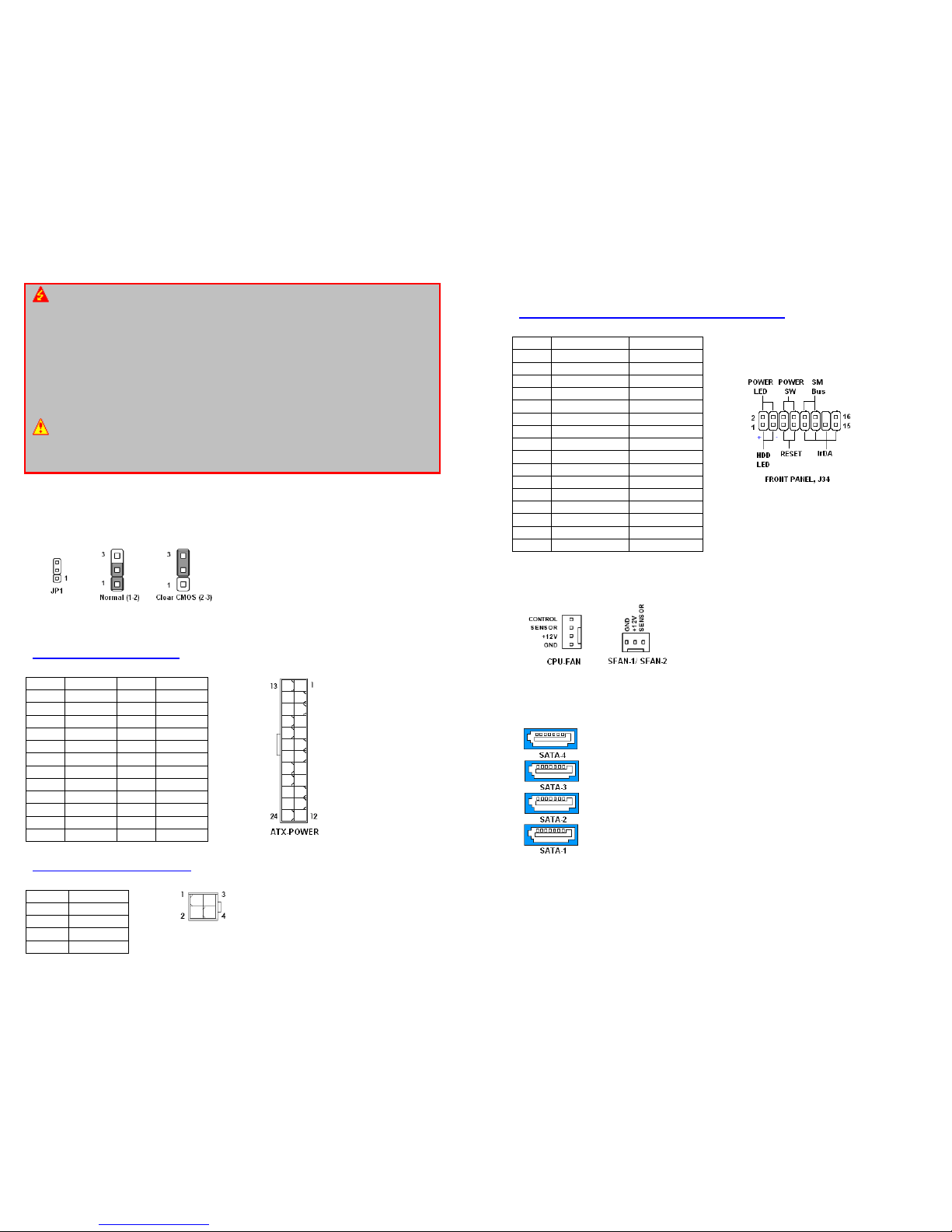
WARNING: Electrostatic Sensitive Device (ESD)
Static electricity can easily damage your motherboard and will void your motherboard
warranty. Keep the motherboard and other system components in their anti-static packaging
until you are ready to install them. Touch a grounded surface before you remove any system
component from its protective anti-static packaging. Unpacking and installation should be
done on a grounded, anti-static mat. The operator should be wearing an anti-static wristband,
grounded at the same points as the anti-static mat. During configuration and installation
touch a grounded surface frequently to discharge any static electrical charge that may have
built up in your body. Avoid touching the components when handling the motherboard or a
peripheral card. Handle the motherboard and peripheral cards either by the edges or by the
peripheral card case-mounting bracket.
WARNING: Misplaced Jumper Damage
Incorrect setting jumpers and connectors may lead to damage to your motherboard and will
void your motherboard warranty. Please pay special attention not to connect these headers
in wrong directions. DO NOT change ANY jumpers while the motherboard has the power!
Connectors, Jumpers, & Headers
• Clear CMOS Jumper (JP1):
• ATX Power Connectors (ATX-POWER, ATX-POWER-4P):
ATX-POWER (J36, 24-pin)
ATX-POWER-4P (J12, 4-pin)
Pin Signal Pin Signal
1 +3.3V 13 +3.3V
2 +3.3V 14 -12V
3 GND 15 GND
4 +5V 16 PS-ON#
5 GND 17 GND
6 +5V 18 GND
7 GND 19 GND
8 PWROK 20 Res
9 5VSB 21 +5V
10 +12V 22 +5V
11 +12V 23 +5V
12 +3.3V 24 GND
Pin Signal
1 GND
2 GND
3 +12V
4 +12V
• Front Panel Connectors (Front Panel, J34):
(Power SW, Reset SW, Power LED, Reset LED)
• Fan Power Connectors (CPU-FAN, SFAN-1, SFAN-2):
• SATA Ports (SATA-1, SATA-2, SATA-3, SATA-4):
Pin Signal Description
1 HD_LED+ HD LED+
2 PWR/SLPLED+ Power LED+
3 HD_LED- HD LED-
4 PWR/SLPLED- Power LED-
5 RST_SW ResetSwitch
6 PWR_SW PowerSwitch
7 RST_SW ResetWitch
8 PWR_SW PowerSwitch
9 IrDA IrDA Power
10 SM Bus SM Bus Data
11 IrDA IrDA Receive
12 SM Bus SM Bus Clock
13 IrDA IrDA Ground
14 key N.C.
15 IrDA IrDA Transmit
16 No signal N.C.
Page 3
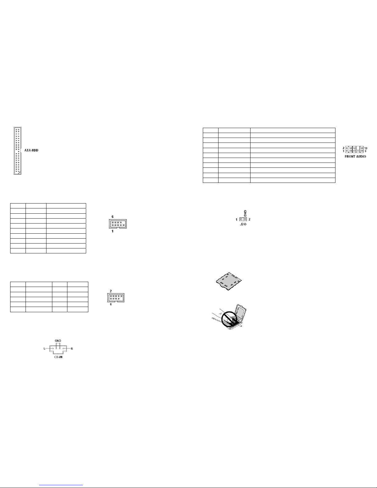
• IDE Connector (ATA-HDD, J30):
• Serial Port Connector (COM-1):
• Front USB Headers (FRONT USB-1, FRONT USB-2):
• Optical Drive Audio Connector (CD-IN):
Pin Signal Description
1 DCD Data Carry Datect
2 RxD Receive Data
3 TxD Transmit Data
4 DTR Data Terminal Ready
5 GND Ground
6 DSR Data Set Ready
7 RTS Request to Send
8 CTS Clear to Send
9 RI Ring Indicate
Pin Signal Pin Signal
1 VCC 2 VCC
3 USB0- 4 USB1-
5 USB0+ 6 USB1+
7 GND 8 GND
9 KEY(no pin) 10 N.C.
• Front Panel Audio Connector (FRONT AUDIO, J6):
• Chassis Intrusion Connector (J20):
• Save the Processor Socket Cover
After removing the processor cover during processor installation, please save the processor socket
cover.
In the event that the motherboard needs to be returned for service (e.g. RMA) or any time the processor
is removed, the cover should be placed on top of the processor socket.
• Do not Touch Socket Contact
Pin Signal Description
1 AUD_MIC Front panel microphone input
2 AUD_GND Analog audio circuits Ground
3 AUD_MIC_BIAS Microphone Power
4 AUD_VCC Analog Audio Circuit 3V+
5 AUD_FPOUT_R Right Channel audio Signal to Front Panel
6 AUD_RET_R Right Channel Audio Signal Return From Front Panel
7 HP_ON Reserved for future use
8 KEY No pin
9 AUD_FPOUT_L Left Channel Audio Signal to Front Panel
10 AUD_RET_L Left Channel Audio Signal Return From Front Panel
 Loading...