

Page 1

RX110H
Intel® Sky Lake (6th gen i7/i5/i3)/
Kaby Lake (7
th
gen i7/i5/i3)
Micro-ATX Mainboard
BCM P/N: 71172 ONLY
User’s Manual
Edition 1.00 – Feb, 2017
1
Page 2

FCC Statement
THIS DEVICE SUPPORTS PART 15 FCC RULES. OPERATION IS SUBJECT TO THE FOLLOWING TWO
CONDITIONS:
(1) THIS DEVICE MAY NOT CAUSE HARMFUL INTERFERENCE.
(2) THIS DEVICE MUST ACCEPT ANY INTERFERENCE RECEIVED INCLUDING INTERFERENCE THAT MAY CAUSE
UNDESIRED OPERATION.
THIS EQUIPMENT HAS BEEN TESTED AND FOUND TO COMPLY WITH THE LIMITS FOR A CLASS "A" DIGITAL DEVICE,
PURSUANT TO PART 15 OF THE FCC RULES.
THESE LIMITS ARE DESIGNED TO PROVIDE REASONABLE PROTECTION AGAINST HARMFUL INTERFERENCE WHEN THE
EQUIPMENT IS OPERATED IN A COMMERCIAL ENVIRONMENT. THIS EQUIPMENT GENERATES, USES, AND CAN RADIATE
RADIO FREQUENCY ENERGY AND, IF NOT INSTATLLED AND USED IN ACCORDAN CE WITH THE INSTRUCTION MANUAL,
MAY CAUSE HARMFUL INTERFERENCE TO RADIO COMMUNICATIONS.
OPERATION OF THIS EQUIPMENT IN A RESIDENTIAL AREA IS LIKELY TO CAUSE HARMFUL INTERFERENCE IN WHICH
CASE THE USER WILL BE REQUIRED TO CORRECT THE INTERFERENCE AT HIS OWN EXPENSE.
Notice
This guide is designed for experienced users to setup the system within the shortest time. For detailed
information, please always refer to the electronic user's manual.
Copyright Notice
Copyright © 2017 BCM Advanced Research, ALL RIGHTS RESERVED.
No part of this document may be reproduced, copied, translated, or transmitted in any form or by any
means, electronic or mechanical, for any purpose, without the prior written permission of the original
manufacturer.
Trademark Acknowledgement
Brand and product names are trademarks or registered trademarks of their respective owners.
2
Page 3

Disclaimer
BCM Advanced Research reserves the right to make changes, without notice, to any product, including
circuits and/or software described or contained in this manual in order to improve design and/or
performance. BCM Advanced Research assumes no responsibility or liability for the use of the described
product(s), conveys no license or title under any patent, copyright, or masks work rights to these products,
and makes no representations or warranties that these products are free from patent, copyright, or mask
work right infringement, unless otherwise specified. Applications that are described in this manual are for
illustration purposes only. BCM Advanced Research makes no representation or warranty that such
application will be suitable for the specified use without further testing or modification.
Life Support Policy
BCM Advanced Research PRODUCTS ARE NOT FOR USE AS CRITICAL COMPONENTS IN LIFE
SUPPORT DEVICES OR SYSTEMS WITHOUT THE PRIOR WRITTEN APPROVAL OF BCM Advanced
Research.
As used herein:
1. Life support devices or systems are devices or systems which, (a) are intended for surgical implant into
body, or (b) support or sustain life and whose failure to perform, when properly used in accordance with
instructions for use provided in the labeling, can be reasonably expected to result in significant injury to
the user.
2. A critical component is any component of a life support device or system whose failure to perform can
be reasonably expected to cause the failure of the life support device or system, or to affect its safety
or effectiveness.
3
Page 4

A Message to the Customer
BCM Customer Services
Each and every BCM product is built to the most exacting specifications to ensure reliable performance in
the harsh and demanding conditions typical of industrial environments. Whether your new BCM device is
destined for the laboratory or the factory floor, you can be assured that your product will provide the
reliability and ease of operation for which the name BCM has come to be known.
Your satisfaction is our primary concern. Here is a guide to BCM customer services. To ensure you get the
full benefit of our services, please follow the instructions below carefully.
Technical Support
We want you to get the maximum performance from your products. So if you run into technical difficulties,
we are here to help. For the most frequently asked questions, you can easily find answers in your product
documentation. These answers are normally a lot more detailed than the ones we can give over the phone.
So please consult the user’s manual first.
To receive the latest version of the user’s manual and drivers; please visit our Web site at:
http://www.bcmcom.com.
If you still cannot find the answer, gather all the information or questions that apply to your problem, and
with the product close at hand, call your dealer. Our dealers are well trained and ready to give you the
support you need to get the most from your BCM products. In fact, most problems reported are minor and
are able to be easily solved over the phone.
In addition, free technical support is available from BCM engineers every business day. We are always
ready to give advice on application requirements or specific information on the installation and operation of
any of our products. Please do not hesitate to call or e-mail us.
BCM Advanced Research
11 Chrysler,
Irvine, California, 92618
USA
Tel : +1-949-470-1888
Fax : +1-949-470-0971
http://www.bcmcom.com
E-mail: [email protected]
4
Page 5

Product Warranty
BCM warrants to you, the original purchaser, that each of its products will be free from defects in materials
and workmanship for two years from the date of purchase.
This warranty does not apply to any products which have been repaired or altered by persons other than
repair personnel authorized by BCM, or which have been subject to misuse, abuse, accident or improper
installation. BCM assumes no liability under the terms of this warranty as a consequence of such events.
Because of BCM high quality-control standards and rigorous testing, most of our customers never need to
use our repair service. If any of BCM products is defective, it will be repaired or replaced at no charge
during the warranty period. For out-of-warranty repairs, you will be billed according to the cost of
replacement materials, service time, and freight. Please consult your dealer for more details. If you think
you have a defective product, follow these steps:
1. Collect all the information about the problem encountered. (For example, CPU type and speed, BCM
products model name, hardware & BIOS revision number, other hardware and software used, etc.)
Note anything abnormal and list any on-screen messages you get when the problem occurs.
2. Call your dealer and describe the problem. Please have your manual, product, and any helpful
information available.
3. If your product is diagnosed as defective, obtain an RMA (return material authorization) number from
your dealer. This allows us to process your good return more quickly.
4. Carefully pack the defective product, a complete Repair and Replacement Order Card and a
photocopy proof of purchase date (such as your sales receipt) in a shippable container. A product
returned without proof of the purchase date is not eligible for warranty service.
Write the RMA number visibly on the outside of the package and ship it prepaid to your dealer.
5
Page 6
Manual Objectives
This manual describes in detail the BCM RX110H mainboard.
We strongly recommend that you study this manual carefully before attempting to interface with the
motherboard or change the standard configurations. Whilst all the necessary information is avai lable in thi s
manual we would recommend that unless you are confident, you contact your supplier for guidan ce.
Please be aware that it is possible to create configurations within the CMOS RAM that make booting
impossible. If this should happen, clear the CMOS settings, (see the description of the Jumper Settings for
details).
If you have any suggestions or find any errors concerning this manual and want to inform us of these,
please contact our Customer Service department with the relevant details.
Safety Precautions
Warning!
Always completely disconnect the power cord from your chassis whenever you
work with the hardware. Do not make connections while the power is on. Sensitive
electronic components can be damaged by sudden power surges. Only
experienced electronics personnel should open the PC chassis.
Caution!
Always ground yourself to remove any static charge before touching the
mainboard. Modern electronic devices are very sensitive to static electric charges.
As a safety precaution, use a grounding wrist strap at all times. Place all electronic
components in a static-dissipative surface or static-shielded bag when they are not
in the chassis.
Document Amendment History
Revision Date Comment
st
1
(1.00) Feb, 2017 Initial Release
6
Page 7

Contents
Chapter 1: System Setup .............................................................................................. 12
1.1 Welcome! ........................................................................................................................................ 12
1.2 Packing Contents ........................................................................................................................... 12
1.3 Special Features ............................................................................................................................. 13
1.3.1 Product Highlights .......................................................................................................................... 13
1.4 Before you proceed ........................................................................................................................ 14
1.5 Mainboard Overview ....................................................................................................................... 15
1.5.1
Mounting Holes ............................................................................................................................... 15
1.5.2
Onboard LEDs ................................................................................................................................ 16
1.5.3 Mainboard Layout ........................................................................................................................... 17
1.5.4 Layout Content List ......................................................................................................................... 18
1.5.4.1 Slots ................................................................................................................................................ 18
1.5.4.2 Internal Jumpers ............................................................................................................................. 18
1.5.4.3 Internal Headers ............................................................................................................................. 19
1.5.4.4 Back Panel Connectors .................................................................................................................. 20
1.6 System Memroy .............................................................................................................................. 21
1.6.1 Overview ......................................................................................................................................... 21
1.6.2 Memory Configurations .................................................................................................................. 21
1.6.3 Installing the DDR4 DIMM .............................................................................................................. 22
1.6.4 Removing the DDR4 DIMM
1.7 Power Supply .................................................................................................................................. 24
1.7.1 ATX Power Connectors: A TXPWR1, A TX12V1 .............................................................................. 24
1.8 Back Panel ...................................................................................................................................... 25
1.8.1 Back Panel Connectors .................................................................................................................. 25
1.9 Connectors/Headers ....................................................................................................................... 27
1.9.1
USB3.0 Header: USB3_3_4 ........................................................................................................... 27
1.9.2
Serial ATA 3.0 Connectors: SATA3_1, SATA3_2, SATA3_3, SATA3_4 ....................................... 27
1.9.3 Digital Input/ Output Header: JGPIO1 ............................................................................................ 28
1.9.4 CPU & System Fan Connectors: CPU_FAN1, CHA_FAN1, CHA_FAN2 ...................................... 29
1.9.5 External Buzzer Connector: BUZZ2 ............................................................................................... 30
1.9.6 System Panel Header: PANEL1 ..................................................................................................... 30
1.9.7 Chassis Intrusion Headers: CI1, CI2 .............................................................................................. 31
......................................................................................... 23
1.9.8 USB2.0 Headers: USB2_0_1, USB2_2_3 ...................................................................................... 31
1.9.9 COM2, COM3, COM4, COM5, COM6 Headers (RS232 ONLY): COM2, COM3, COM4, COM5,
7
Page 8

COM6 ............................................................................................................................................. 32
1.9.10 LPT Port Header: LPT1 .................................................................................................................. 32
1.9.11 3W Audio AMP Output: SPEAKER1 .............................................................................................. 33
1.9.12 Front Panel Audio Header: HD_AUDIO1 ....................................................................................... 34
1.10
Jumpers .......................................................................................................................................... 35
1.10.1 COM1 Pin#9 Power Setting Jumper: PWR_COM1 ........................................................................ 35
1.10.2 Rear I/O USB Ports Power Setting Jumpers: USB2_PWR1 (For USB2.0 Port "USB2_89"),
USB3_PWR1 (For USB3.0 Port "USB3_45") ................................................................................. 35
1.10.3 USB Power Setting Jumper for USB3.0 Header "USB3_3_4": USB3_PWR2 ............................... 36
1.10.4 GPIO Input/ Output Power Select: JGPIO_PWR1 ......................................................................... 36
1.10.5 GPIO Signals Pull-High/ Pull-Low Selection: JGPIO_SET1 .......................................................... 37
1.10.6 Clear CMOS Header: CLRMOS1 ................................................................................................... 38
1.10.7 USB Ports Power Settings Jumpers: USB2_PWR2 (For USB2.0 Port "USB2_0_1"), .....................
USB2_PWR3 (For USB2.0 Port "USB2_2_3") ............................................................................... 39
1.10.8 ATX/ AT Mode Select: PWR_JP1 ........................................................................................... ....... 39
1.10.9 COM2/3/4/5/6 Pin#9 Power Setting Jumper: PWR_COM2, PWR_COM3, PWER_COM4,
PWR_COM5, PWR_COM6 ............................................................................................................ 40
1.11 The Expansion Slots ....................................................................................................................... 41
1.11.1
Installation of Expansion Card ........................................................................................................ 41
1.11.2
Setup An Expansion Card .............................................................................................................. 41
Chapter 2: Starting Up the System ............................................................................. 42
2.1 Starting Up Your System ................................................................................................................. 42
Chapter 3: BIOS Setup .................................................................................................. 44
3.1 BIOS Falsh Related Procedure ...................................................................................................... 44
3.2 Introducing BIOS ............................................................................................................................ 44
3.3 Entering BIOS Setup Menu ............................................................................................................ 45
3.4 Getting Help .................................................................................................................................... 45
3.4.1 UEFI Menu Bar ............................................................................................................................... 46
3.4.2 Navigation Keys .............................................................................................................................. 46
3.5 Main Screen .................................................................................................................................... 47
3.6 Advanced Screen ........................................................................................................................... 48
3.6.1 CPU Configuration .......................................................................................................................... 49
3.6.2 Chipset Configuration ..................................................................................................................... 52
3.6.3 Storage Configuration ..................................................................................................................... 54
3.6.4
Super IO Configuration ................................................................................................................... 55
3.6.5
ACPI Configuration ......................................................................................................................... 57
8
Page 9

3.6.6 USB Configuration .......................................................................................................................... 59
3.6.7
Trusted Computing ......................................................................................................................... 60
3.7
Hardware Health Event Monitoring Screen .................................................................................... 61
Security Screen .............................................................................................................................. 63
3.8
3.9
Boot Screen .................................................................................................................................... 64
3.9.1
CSM (Compatibility Support Module) ............................................................................................. 65
3.10
Exit Screen ..................................................................................................................................... 67
Chapter 4: Application Note .......................................................................................... 68
9
Page 10

Mainboard Specifications
Model RX110H
Processor Intel® 6th Generation LGA1151 core i3, Core i5, Core i7 (Sky Lake)
Intel® 7th Generation LGA1151 core i3, Core i5, Core i7 (Kaby Lake)
Note: BCM P/N: 71172 ONLY
Chipset Intel® H110
Memory
Display Intel® Integrated Graphic (CPU Dependent)
SATA 4 x SATA III connectors
Expansion Slots 1x PCIe x16 Slot
USB 6 x USB 2.0 ports (4 @ 2x Header, 2 @ Rear I/O)
Super I/O Controller Nuvoton® NCT6106D
Serial Ports 1 x RS232/RS422/RS485 port (Rear I/O, Selectable through BIOS, with 5V/12V/RI
LPT 1 x LPT header
Watch Dog Timer 1 ~ 255 sec timer
HW Monitor Yes
2 x 288Pin DIMM sockets support Non-ECC, Un-buffered DD R4 memory module
(PC4-17000) 2133 MHz up to 32GB (16GB maximum/slot)
1 x DVI-D port
2 x Display port
3x PCIe x1 Slot
4 x USB 3.0 ports (2 @ 1x Header, 2 @ Rear I/O)
selection jumper, )
5 x RS232 Ports (Header, with 5V/12V/RI selection jumper)
Audio Realtek® ALC887
LAN 1 x 10/100/1000 LAN (Intel® i219-V PHY Gigabit LAN)
DIO 8 Bit
BIOS
Onboard I/O Headers
SATA 4 x Std. SATA III Connectors
USB 2 x USB2.0 Headers (2 ports on each header)
1 x 10/100/1000 LAN (Intel® i211-AT PCIe Gigabit LAN)
AMI® UEFI BIOS
AMI BIOS with 16MB (128Mbit) SPI ROM
1 x USB3.0 Header (2 ports on each header)
10
Page 11
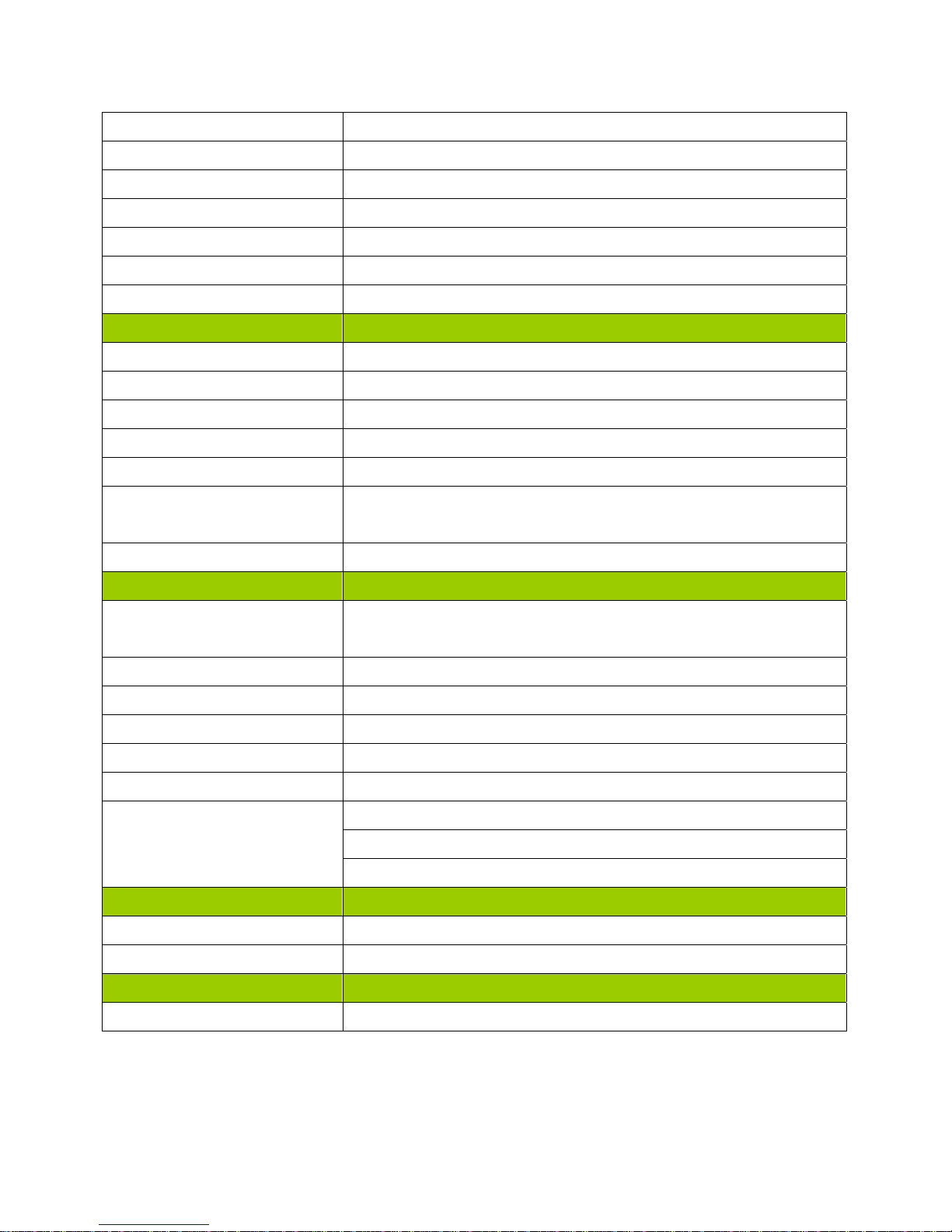
RS232 5 x Headers
LPT 1 x Header
Front Audio 1 x Header
Amplifier 1 x Header
Front Panel 1 x Header
Fan Header 3 x Headers (4-pins)
GPIO 1 x Header
Onboard Jumpers
COM Port Ring-In/ Power Select 5 x Headers provide selection of “Ring-In”, or “12V” or “5V” on RS232 COM port
AT/ATX Select 1 x Header
Clear CMOS 1 x Header
USB Port Power Setting 5 x Header provide selection of 5V or 5VSB
GPIO Input/ Output Power Select 1 x Header provide selection of 12V or 5V
GPIO Signal Pull-High/ Pull-Low
Selection
Rear I/O Panel
PS/2 1x PS/2 Keyboard Connector
DVI 1 x DVI-D Connector
DP (Display Port) 2 x DP Connector
USB3.0 2x Stack up USB3.0 Connector (Blue)
USB2.0 2x Stack up USB2.0 Connector (Black)
LAN 2 x RJ45 Connector
Audio 1 x Line-In
Power & Connector
1 x 24 pin ATX Connector (AC)
1 x Header provide selection of “Pull-High to 3V” or “Pull-Low to Ground”
1 x PS/2 Mouse Connector
1 x Line-Out
1 x Mic-In
1 x 4 pin ATX 12V Connector
Form Factor
uATX 9.6” x 9.6”
11
Page 12

Chapter 1: System Setup
This chapter describes the mainboard features and the new technologies it supports
1.1 Welcome!
The mainboard delivers a host of new features and latest technologies, making it another line of BCM
long life mainboards! Before you start installing the mainboard, and hardware devices on it, check the
items in your package with the list below.
If any of the items listed below is damaged of missing, please contact with your vendor.
1.2 Packing Contents
• Mainboard
• 1 x RX110H
• Cable
• 2 x SATA Power Cable
• Accessories
• 1 x RX110H I/O Shield
12
Page 13

1.3 Special Features
1.3.1 Product Highlights
• The 6th/ 7th Generation Intel® i7/i5/i3 LGA1151 Processor Support (BCM P/N: 71172 ONLY)
This mainboard supports the 6th generation Intel® i7/i5/i3 processors (Sky Lake) & 7
i7/i5/i3 processors (Kaby Lake) in the LGA1151 package.
• Intel® H110 Express Chipset
The Intel® H110 PCH provides all business with more effective costs management, safer computing
environment, and deploys more responsive PCs.
• DDR4 Memory Support
The mainboard supports DDR4 memory that features data transfer rate up to 2133MHz to meet the higher
bandwidth requirements of the latest 3D graphics, multimedia, and Internet applications.
• High Definition Audio
th
generation Intel®
The mainboard came with the Realtek ALC887 high-definition audio CODEC that lets you enjoy high
quality audio without having to buy advanced sound cards.
• PCI-E x16 support
The PCI-E x16 VGA interface specification enhances graphics performance with high band width (PCIEX16
slot only).
• USB 3.0 Technology
The mainboard implements the Universal Serial Bus (USB) 3.0.
• Trusted Platform Module (TPM) Support (Optional)
By combining the onboard TPM 1.2 with TPM security software (provided by the third party), it will enhance
the security level of the system.
• PRECAUTION: When TPM is enabled and utilized through TPM software, there is
possibility that the encrypted data will not be accessible, or recoverable if one of th e
following situations occurred:
1. Lost of TPM password.
2. System or board failure, or being replaced.
3. Hard Drive failure.
13
Page 14

1.4 Before you proceed
Take note of the following precautions before you install mainboard components or chang e any
mainboard settings.
• Unplug the power cord from the wall socket before touching any component inside the
system.
• Use a grounded wrist strap or touch a safely grounded object or to a metal object, such as the
power supply case, before handling components to avoid damaging them due to static
electricity.
• Hold peripherals by the edges to avoid touching the ICs on them.
• Whenever you uninstall any peripheral, place it on a grounded antistatic pad or on the bag
that came with the peripheral.
• Before you install or remove any peripheral, ensure that the power supply is switched off or
the power cord is detached from the power supply. Failure to do so may cause severe
damage to the mainboard, peripherals, and/or components.
14
Page 15
1.5 Mainboard Overview
Before you install the mainboard, study the configuration of your chassis to ensure that the mainboard fits
into it.
Make sure to unplug the power cord before installing or removing the mainboard. Failure
to do so can cause you physical injury and damage mainboard components.
1.5.1 Mounting Holes
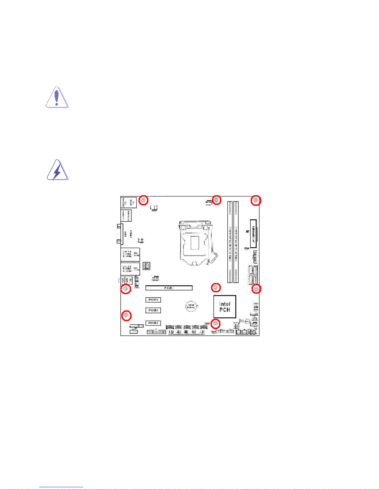
Place the screws into the mounting holes indicated by red circles (shown in the picture below) to secure the
mainboard to the chassis.
Do not over-tighten the screws! Doing so may damage the mainboard.
15
Page 16
1.5.2 Onboard LEDs
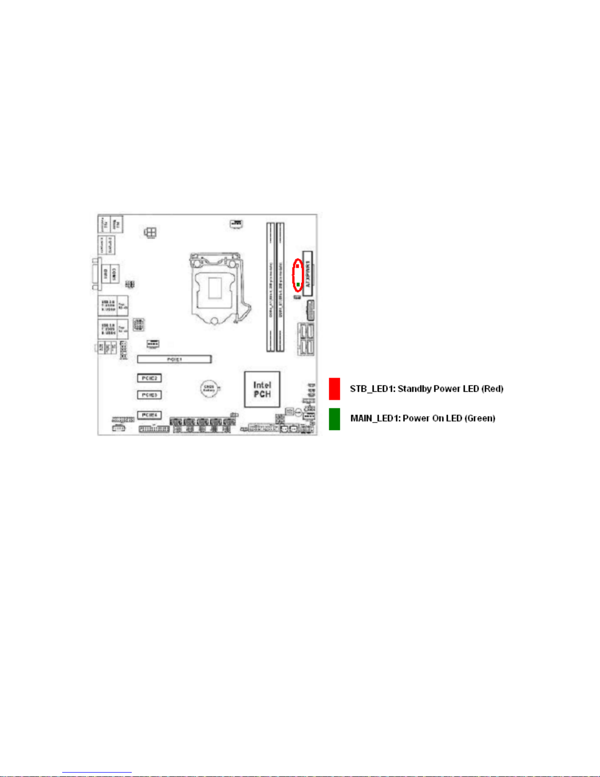
The mainboard comes with a “Power On LED” (green) and one “Standby Power LED” (red) to indicate the
system status. When the “Standby Power LED” lights on: It means the system is either in the standby state,
or the power cable is still connected to the power source. The “Power On LED” lights on/off to indicate that
the system status, in sleep mode, or in soft-off mode. This is a reminder that you should shut down the
system and unplug the power cable before removing or plugging in any mainboard component. The
illustration below shows the locations of onboard LEDs.
16
Page 17
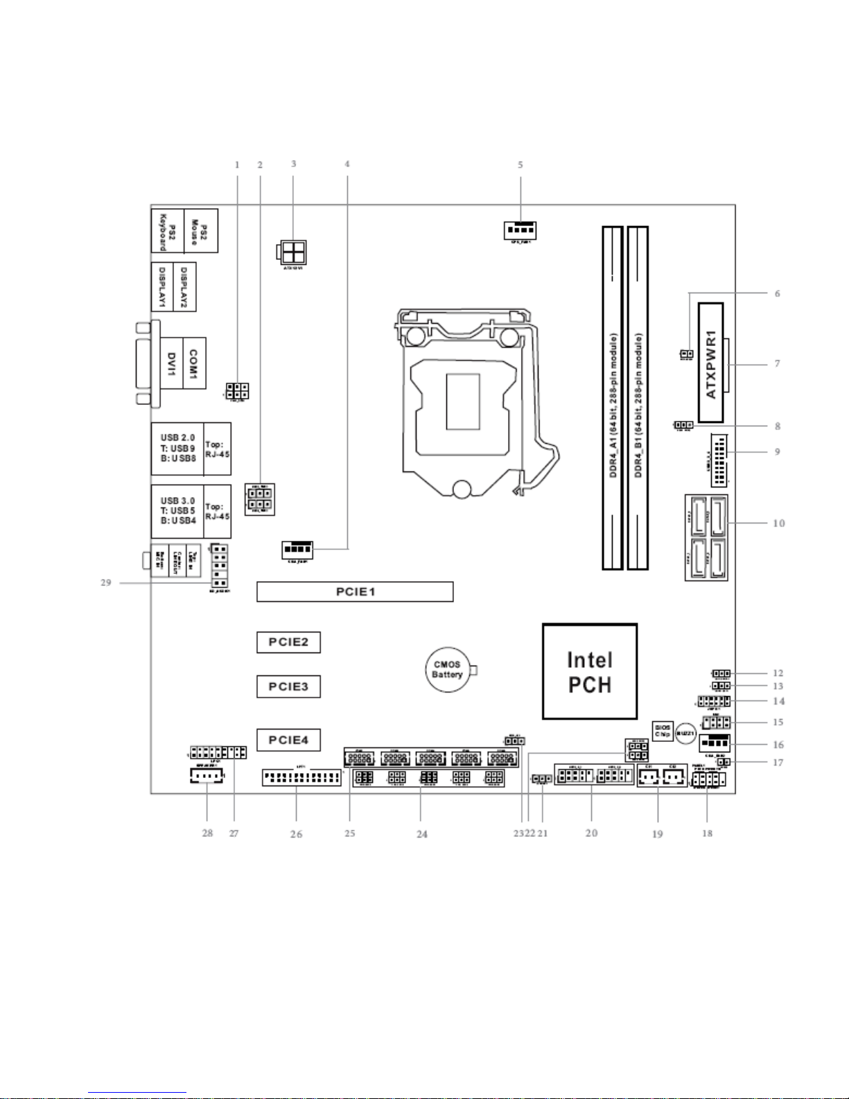
1.5.3 Mainboard Layout
17
Page 18
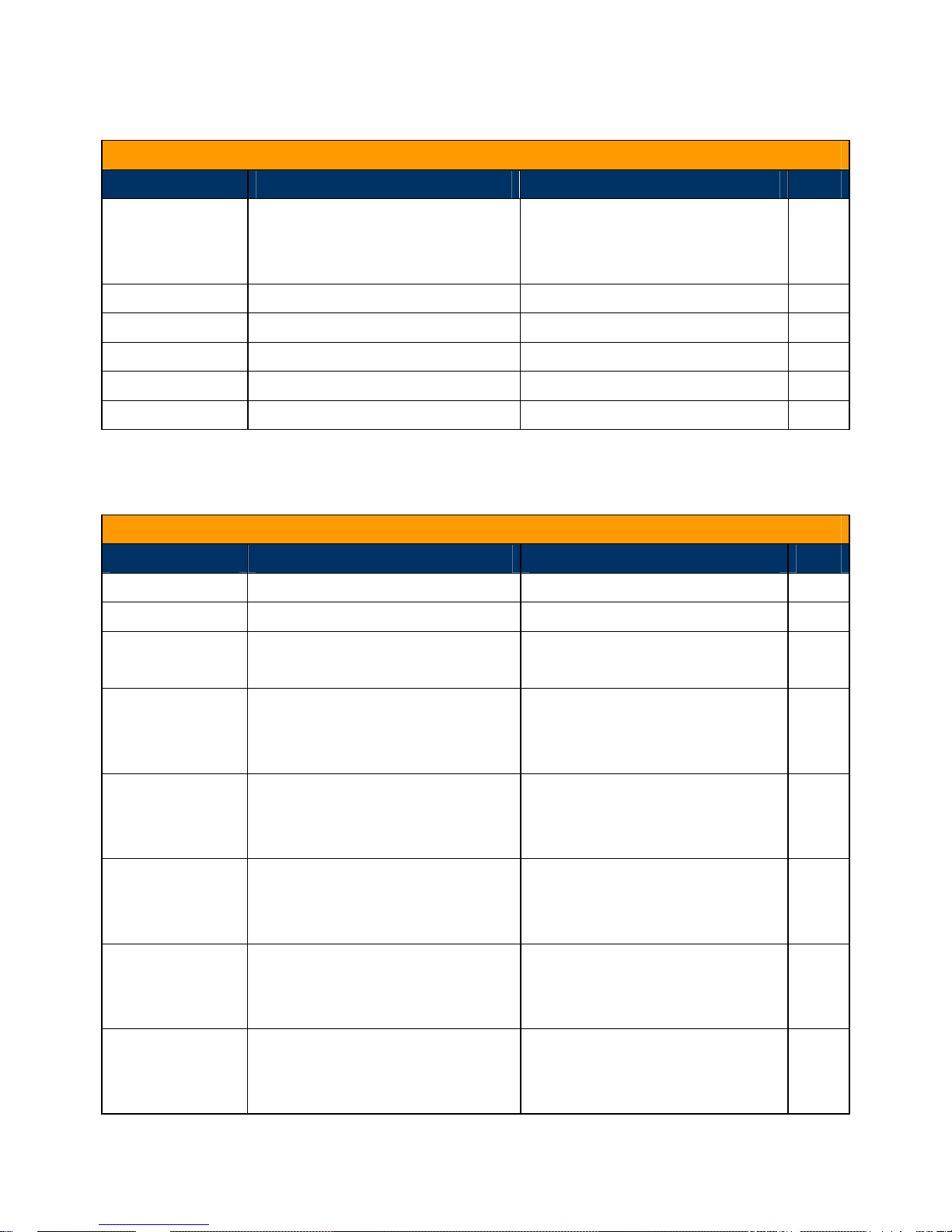
1.5.4 Layout Content List
• 1.5.4.1 Slots
Label Function Note Page
DDR4_A1 288-pin DDR4 DIMM slot A1 1. If there is only one memory
module being installed in the
system, install it on this slot.
DDR4_B1 288-pin DDR4 DIMM slot B1 21
PCIE1 PCI Express x16 slot 41
PCIE2 PCI Express x1 slot 41
PCIE3 PCI Express x1 slot 41
PCIE4 PCI Express x1 slot 41
21
• 1.5.4.2 Internal Jumpers
Label Function Note Page
CLRMOS1 Clear CMOS 3 x 1 header, pitch 2.54mm 38
PWR_JP1 AT/ATX Power Select 3 x 1 header, pitch 2.54mm 39
PWR_COM1 COM1 RI (default)/ +5V/ +12V
3 x 2 header, pitch 2.54mm 35
USB2_PWR1
(For USB2.0 Port
“USB2_89”)
USB3_PWR1
(For USB3.0 Port
“USB3_45”)
USB3_PWR2
(For USB3.0 Port
“USB3_3_4”)
USB2_PWR2
(For USB2.0 Port
“USB2_0_1”)
USB2_PWR3
(For USB2.0 Port
“USB2_2_3”)
Select
Rear I/O USB 2.0 Ports Power
Select: +5V/ +5VSB (default)
Rear I/O USB 3.0 Ports Power
Select: +5V/ +5VSB (default)
USB 3.0 Header Power Select:
+5V (default) / +5VSB
USB 2.0 Ports Power Setting
Jumpers: +5V/ +5VSB (default)
USB 2.0 Ports Power Setting
Jumpers: +5V/ +5VSB (default)
3 x 1 header, pitch 2.54mm 35
3 x 1 header, pitch 2.54mm 35
3 x 1 header, pitch 2.54mm 36
3 x 1 header, pitch 2.54mm 39
3 x 1 header, pitch 2.54mm 39
18
Page 19
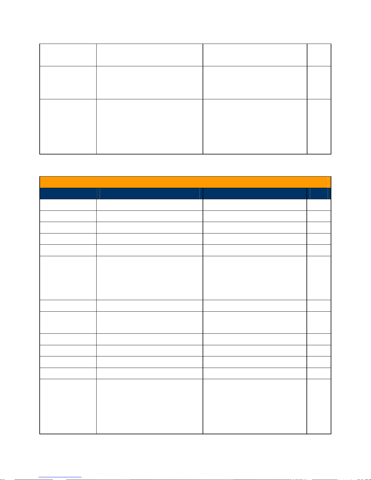
JGPIO_PWR1 GPIO Input/ Output Power Select:
+5V (default) / +12V
3 x 1 header, pitch 2.54mm 36
JGPIO_SET1 GPIO Signals Pull-High/ Pull-Low
Select: Pull-High to +3V (default)/
Pull-Low to Ground
PWR_COM2,
PWR_COM3,
PWR_COM4,
PWR_COM5,
PWR_COM6
COM2/3/4/5/6 Pin#9 Power Setting
Jumper:
Select
RI (default)/ +5V/ +12V
3 x 1 header, pitch 2.54mm 37
3 x 2 header, pitch 2.54mm 40
• 1.5.4.3 Internal Headers
Label Function Note Page
ATX12V1 4-Pin ATX Power Connector 2 x 2 header 24
ATXPWR1 24-Pin ATX Power Connector 12 x 2 header 24
CPU_FAN1 CPU Fan Connector 4 x 1 wafer, Pitch 2.54mm 29
CHA_FAN1 System Fan Connector 1 4 x 1 wafer, Pitch 2.54mm 29
CHA_FAN2 System Fan Connector 2 4 x 1 wafer, Pitch 2.54mm 29
SATA3_1,
SATA3_2,
SATA3_3,
SATA3_4
USB3_3_4 USB3.0 Header (2 Ports) 10 x 2 wafer, pitch 2.00mm 27
USB2_0_1,
USB2_2_3
JGPIO1 Digital Input/ Output Header: 6 x 2 header, pitch 2.00mm 28
BUZZ2 External Buzzer Connector 2 x 1 header, pitch 2.54mm 30
PANEL1 System Panel Header 5 x 2 header, pitch 2.54mm 30
CI1, CI2 Chassis Intrusion Headers 2 x 1 wafer, pitch 2.54mm 31
COM2,
COM3,
COM4,
COM5,
Serial ATA 3.0 Connectors 1~4 7-pin header 27
USB2.0 Headers (2 Ports/ Header) 5 x 2 header, pitch 2.54mm 31
COM2, COM3, COM4, COM5,
COM6 Headers (RS232 ONLY)
5 x 2 wafer, pitch 2.00mm 32
COM6
19
Page 20
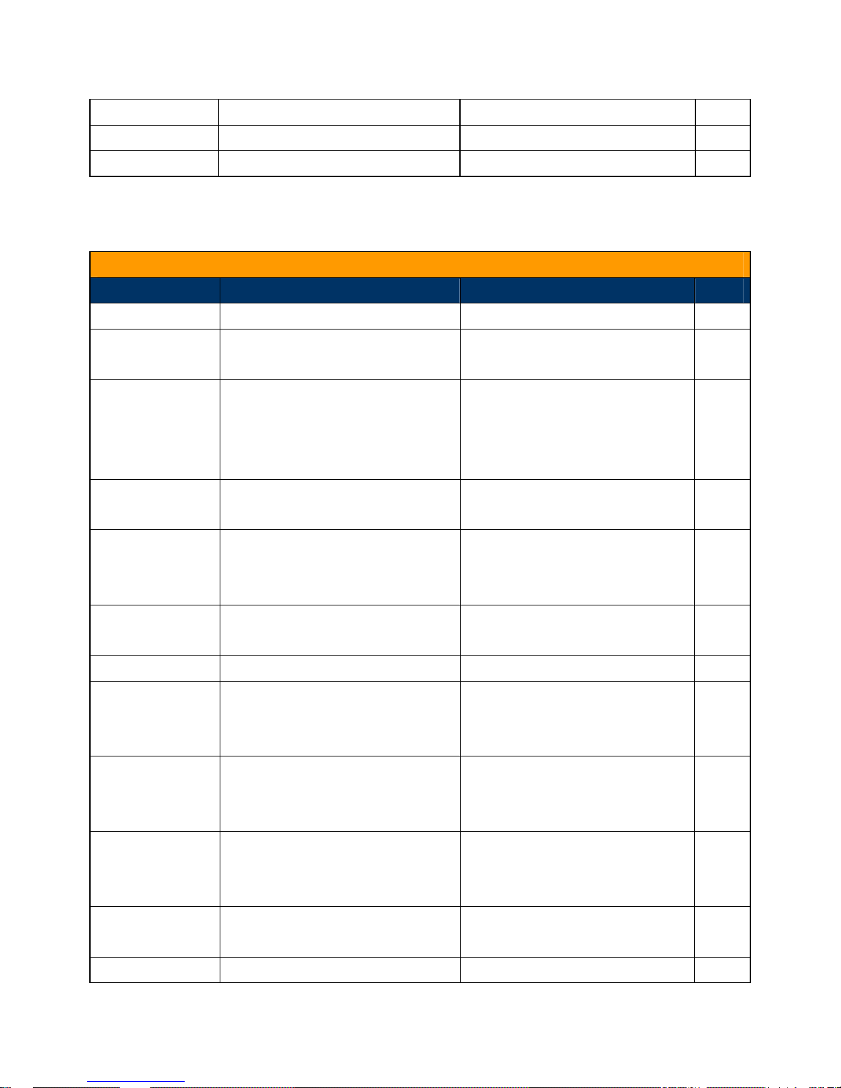
LPT1 LPT Port Header 13 x 2 wafer, pitch 2.00mm 32
SPEAKER1 3W Audio AMP Output 4 x 1 wafer, pitch 2.00mm 33
HD_AUDIO1 Front Panel Audio Header 5 x 2 header, pitch 2.54mm 34
• 1.5.4.4 Back Panel Connectors
Label Function Note Page
PS2_KBMS1 PS/2 Mouse Connector PS/2 Mouse Connection. 25
DP1 Display Port 1 This port provides Display Port
Connection.
COM1 Serial COM Port 1 This port provides serial port
connection. (RS232 (default),
RS422, RS485 Selection available
under BIOS)
LAN1,
LAN2
Audio Lin-in Port (Light Blue) This port connects a tape, CD,
Audio Line-out Port (Green) This port connects a headphone
Audio Microphone Port (Pink) This port connects a microphone. 26
USB3_45 USB3.0 Connectors These two Universal Serial Bus
Gigabit LAN RJ-45 Connector 1/2 25
DVD player, or other audio
sources.
or a speaker.
(USB) ports are available for
25
25
25
26
26
USB2_89 USB2.0 Connectors These two Universal Serial Bus
DVI1 DVI Video Port This port provides DVI-D (Display
DP2 Display Port 2 This port provides Display Port
KBMS PS/2 Keyboard Connector PS/2 Keyboard connection. 26
connecting USB 3.0 devices.
26
(USB) ports are available for
connecting USB2.0 devices.
26
Visual Interface) display
connection.
26
connection.
20
Page 21
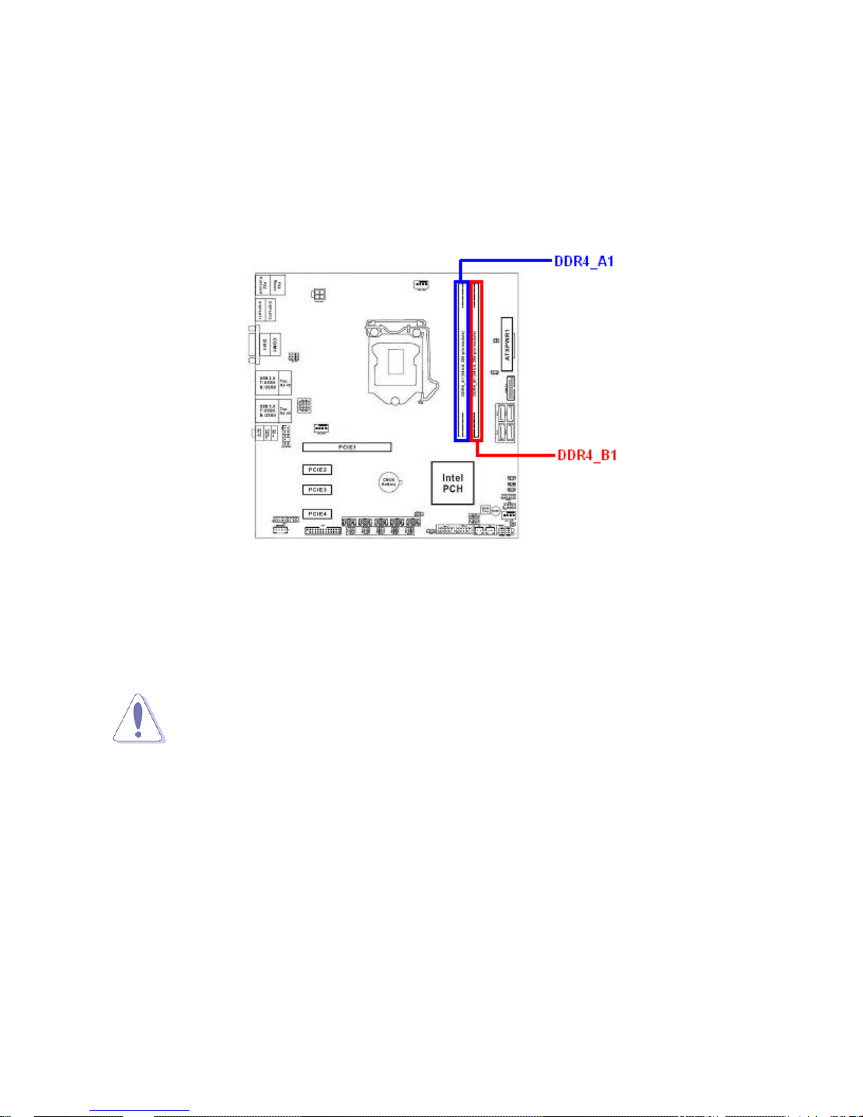
1.6 System Memory
1.6.1 Overview
The mainboard provides two 288-pin DDR4 (Double Data Rate 4) DIMM slots, and supports Dual Cha nnel
Memory Technology.
1.6.2 Memory Configurations
You may ONLY install 288-pin Non-ECC, Un-buffered DDR4 memory module (PC4-17000)
2133 MHz up to 32GB (16GB maximum/slot) on this board.
• When there is only one DDR4 memory module to be installed, install it on
“DDR4_A1” slot ONLY.
• In dual-channel configuration, install only identical (same brand, same
model, same speed, and same chip-type) DDR4 memory modules; one installed at
socket “DDR4_A1”, the other installed at socket “DDR4_B1”.
• Al ways install DIMMs with the same CAS latency. It is recommended that y ou obtain
the exact same model (and same batch) of memory modules from the same vendor.
• It is not allowed to install DDR, DDR2 , or DDR3 memory module on this board.
Doing so may damage the mainboard.
• The DIMM module only fits in one correct orientation. It will cause damage to
the mainboard and the DIMM module if you force the DIMM module into the
memory slot at incorrect orientation.
21
Page 22
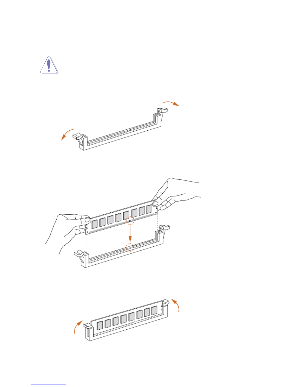
1.6.3 Installing the DDR4 DIMM
Make sure to unplug the power supply before adding or removing DIMMs or other
peripherals from the system. Failure to do so may cause severe damage to both the
mainboard and the peripherals.
1. Unlock a DIMM socket by pressing the retaini ng clips outward.
2. Align a DIMM on the socket such that the notch on the DIMM matches the break on the socket.
3. Firmly insert the DIMM into the socket until the retaining clips snap back in place and the DIMM is
properly seated.
22
Page 23
1. A DDR4 memory module is keyed with a notch so that it fits in only one direction.
2. DO NOT force the memory module into the socket in order to avoid damage the
memory module and the slot.
3. DDR4 memory modules are not interchangeable with DDR, DDR2, or DDR3.
4. DDR4 standard IS NOT backward compatible.
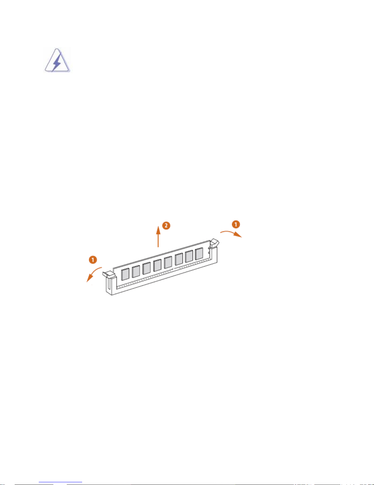
1.6.4 Removing the DDR4 DIMM
Follow these steps to remove a DIMM.
1. Simultaneously press the retaining clips outward to unlock the DIMM.
2. Remove the DIMM from the socket.
23
Page 24
1.7 Power Supply
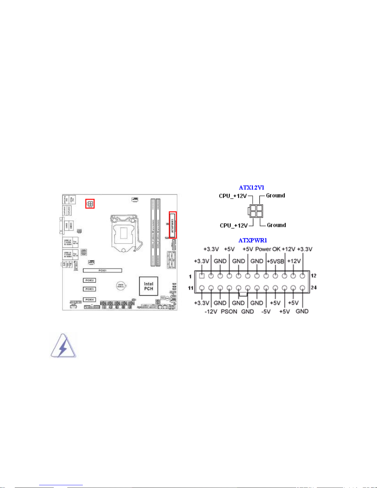
1.7.1 ATX Power Connectors: ATXPWR1, ATX12V1
These ATX power connectors provide connections from power supply unit (PSU) to the mainboa rd.
Both connectors need to be installed in order for the mainboard to function properly. The power
supply plugs are designed to fit with these ATX power connectors in one orientation only. To
connect these power supply plugs; find the proper orientation first, and then push down the power
supply plugs firmly until the connectors are completely fit.
If you’d like to use the 20-pin ATX power supply, please align the 20-pin power connector from
PSU to pin 1 & pin 13 of “EATXPWR1”. There is also a foolproof design on pin 11, 12, 23, & 24 to
avoid wrong installation.
1. It is recommended that you use a power supply unit (PSU) that complies with ATX
12V specification 2.0 (or later version), and provides a minimum power of 500W. If
you are planning to fully loaded the slots and/or use a PCI-E x16 graphic card, a
power supply with minimum power of 600W or more might be needed.
2. Do not forget to connect the 4-pin “ATX12V1” power plug; otherwise, the system
will not boot.
3. Use of a PSU with a higher power output is recommended when configuring a
system with more power-consuming devices. The system may become unstable or
may not boot if the power supply is inadequate.
24
Page 25
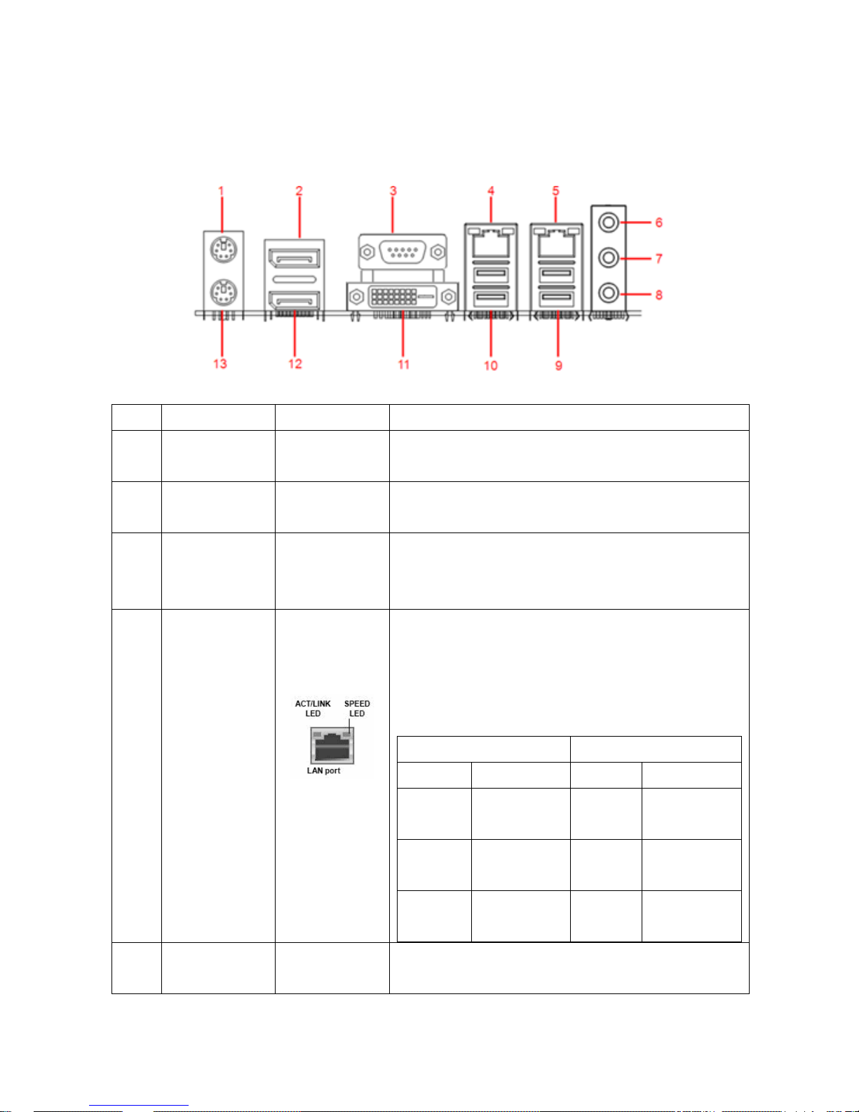
1.8 Back Panel
1.8.1 Back Panel Connectors
Item Name Function Description
1 PS2_KBMS1 PS/2 Mouse
Connector
2 DP1 Display Port
1
3 COM1 Serial COM
Port 1
4/5 LAN1/ LAN2 Gigabit LAN
(RJ-45)
Connectors
This port provides Display Port connection.
(RS232 (default), RS422, RS485 Selection
This port allows Gigabit connection to a Local
Area Network (LAN) through a network hub.
Refer to the table below for the LAN port LED
Status Description Status Description
PS/2 Mouse Connection.
This port provides serial port connection.
available under BIOS)
indications.
ACT/Link LED Speed LED
OFF No link OFF 10Mbps
connection
6 AUDIO Line-in port
(Light blue)
ON Linked Orange 100Mbps
connection
Blinking Data
activity
This port connects a tape, CD, DVD player, or
other audio sources.
25
Green 1Gbps
connection
Page 26

7 AUDIO Line-out port
This port connects a headphone or a speaker.
(Green)
8 AUDIO Microphone
port (Pink)
9 USB3_45 USB 3.0
Connectors
are available for connecting USB 3.0 devices.
10 USB2_89 USB 2.0
Connectors
This port connects a microphone.
These two Universal Serial Bus (USB) ports
These two 4-pin Universal Serial Bus (USB)
ports are available for connecting USB 2.0
devices.
11 DVI1 DVI Video
Port
This port provides DVI-D (Display Visual
Interface) display connection.
12 DP2 Display Port 2 This port provides Display Port connection.
13 KBMS PS/2
Keyboard
PS/2 keyboard Connection.
Connector
26
Page 27
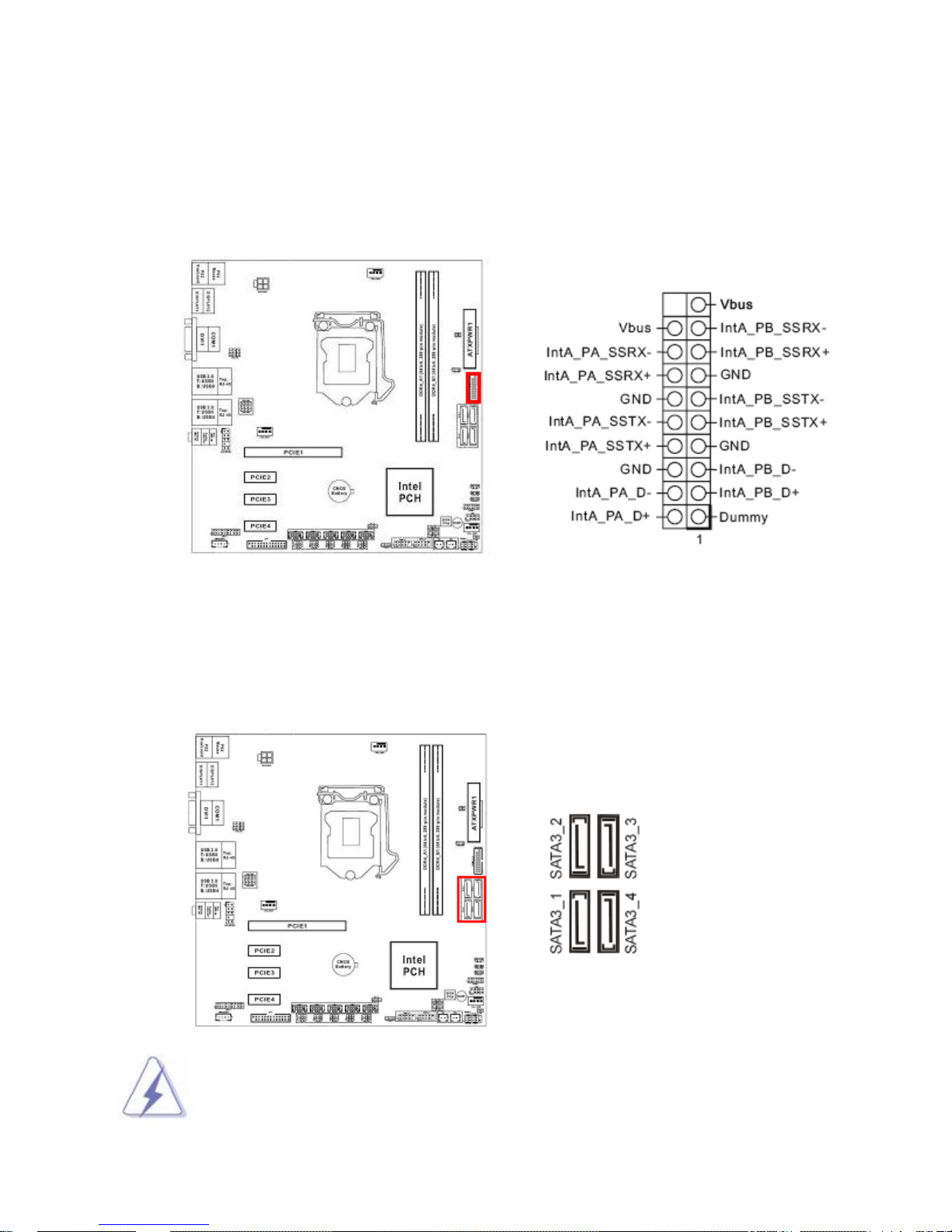
1.9 Connectors/ Headers
1.9.1 USB3.0 Header: USB3_3_4
The internal USB3.0 header (Provides two USB3.0 ports).
1.9.2 Serial ATA 3.0 Connectors:
SATA3_1, SATA3_2, SATA3_3, SATA3_4
SATA ports “SATA3_1”, “SATA3_2”, “SATA3_3”, “SATA3_4” support SATA3.0 standard.
Please do not fold the Serial ATA cable into 90-degree angle, data loss may occur
during data transmission.
27
Page 28
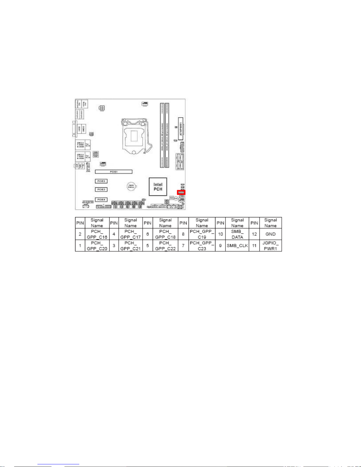
1.9.3 Digital Input/ Output Header: JGPIO1
This header provides 8-bit GPIO connections to external device. Customer can write the
monitoring program to monitor the status of external device connected with this header.
28
Page 29
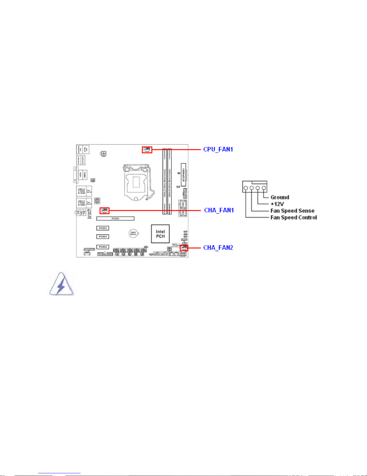
1.9.4 CPU & System Fan Connectors:
CPU_FAN1, CHA_FAN1, CHA_FAN2
The fan power connectors support system cooling fan with +12V. When connecting the wire to
these fan connectors, please note tha t the red wire is designated as “Power” and should be
connected to “+12V” pin; the black wire is designated as “Ground” and should be conne cted to
“GND”. In order to take the advantage of System Hardware Monitor and Smartfan feature, be sure
to use the fan which is specifically designed with speed sensor.
Please refer to the recommended CPU fans at processor’s official website or
consult
with the fan vendor for selection of proper CPU cooling fan.
29
Page 30
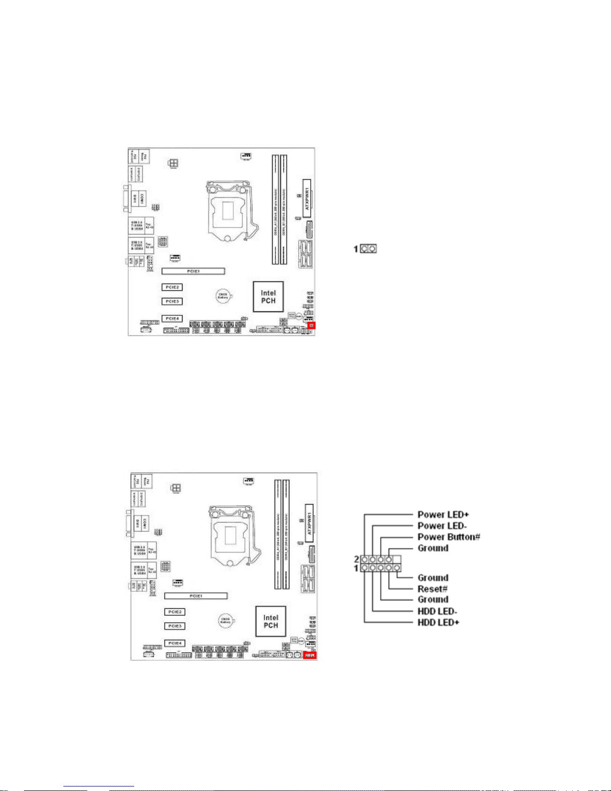
1.9.5 External Buzzer Connector: BUZZ2
This header provides connection to external buzzer on chassis.
1.9.6 System Panel Header: PANEL1
This header provides front panel connections (Power button, Reset button, Power LED, HDD
LED) on chassis.
30
Page 31
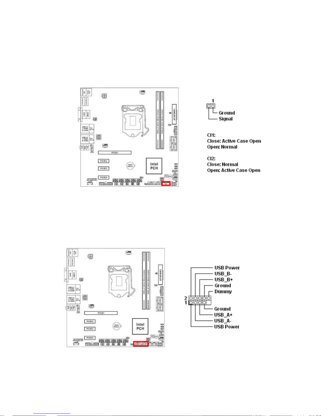
1.9.7 Chassis Intrusion Headers: CI1, CI2
Two chassis instruction headers, choose the one that matches with the chassis intrusion
connection in the chassis.
1.9.8 USB2.0 Headers: USB2_0_1, USB2_2_3
Two internal USB2.0 headers (two USB2.0 ports/ header).
31
Page 32

1.9.9 COM2, COM3, COM4, COM5, COM6 Headers (RS232 ONLY):
COM2, COM3, COM4, COM5, COM6
The COM2, 3, 4, 5, 6 that provides RI in RS232 only.
1.9.10 LPT Port Header: LPT1
This header provides parallel port connection.
32
Page 33
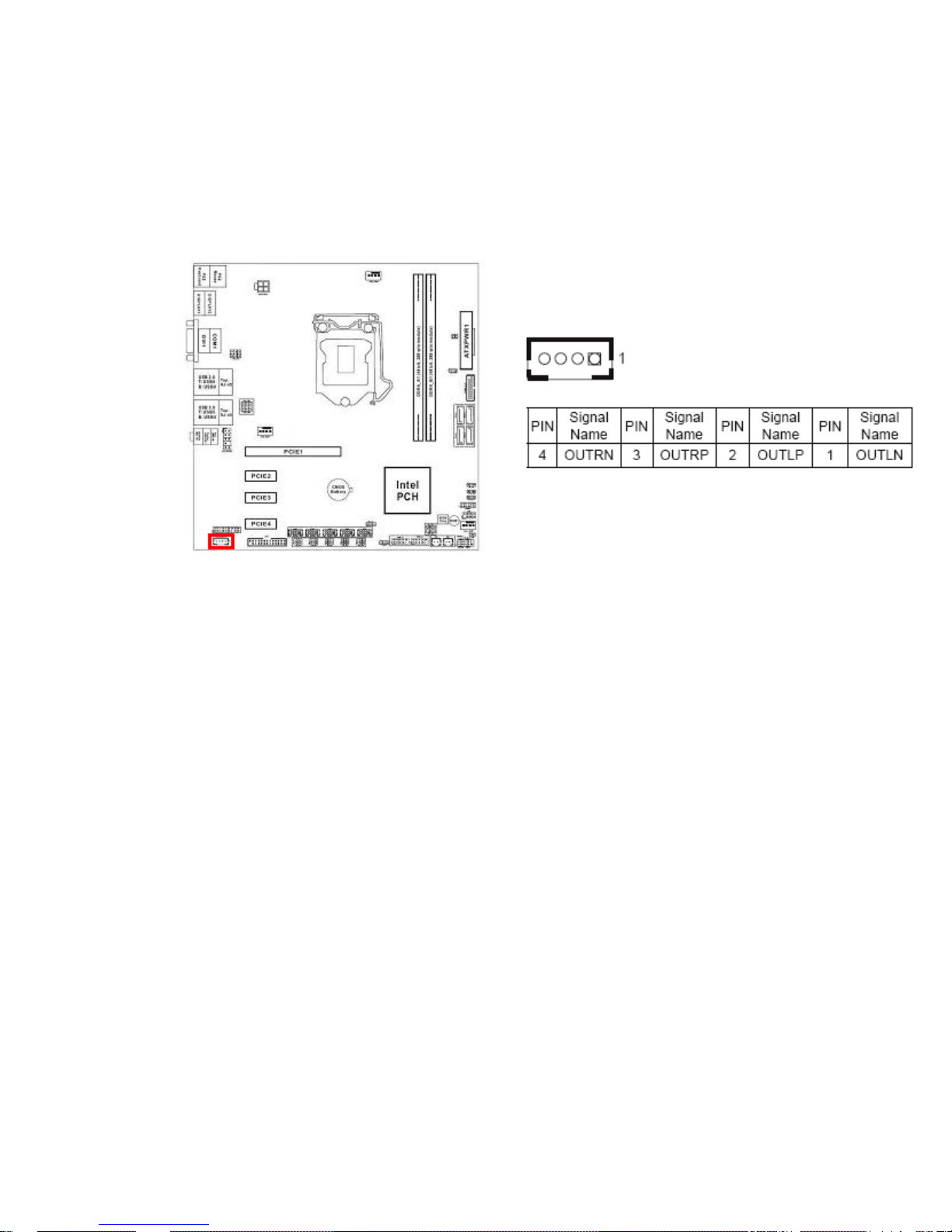
1.9.11 3W Audio AMP Output: SPEAKER1
This header provides amplified speaker output (3W) for simple two external speaker co nnection.
Its volume control is available under the BIOS.
33
Page 34
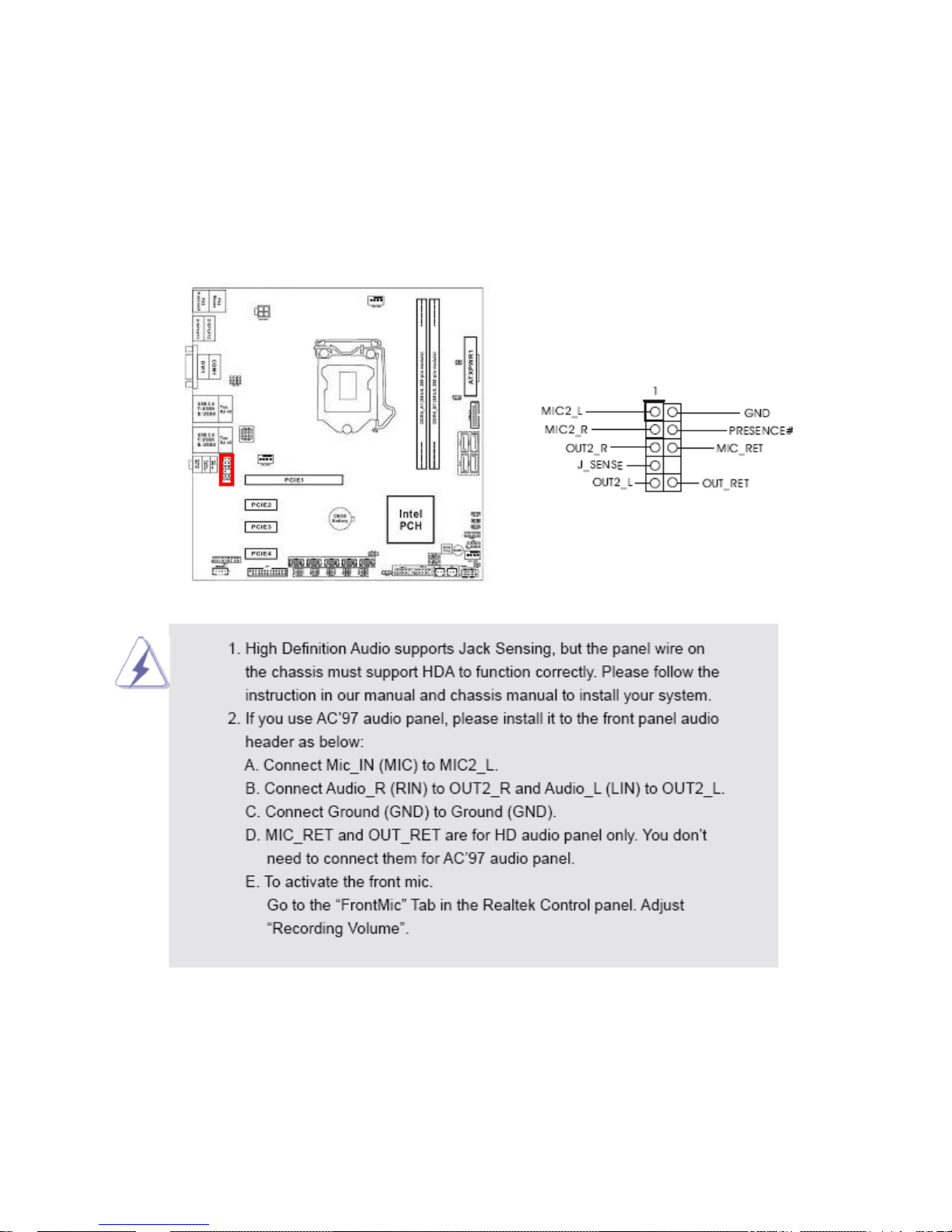
1.9.12 Front Panel Audio Header: HD_AUDIO1
This connector is prepared for a chassis-mounted front panel a ud io I/O module that supports
HD Audio standard. Connect one end of the front panel audio I/O module cable to this
connector.
34
Page 35
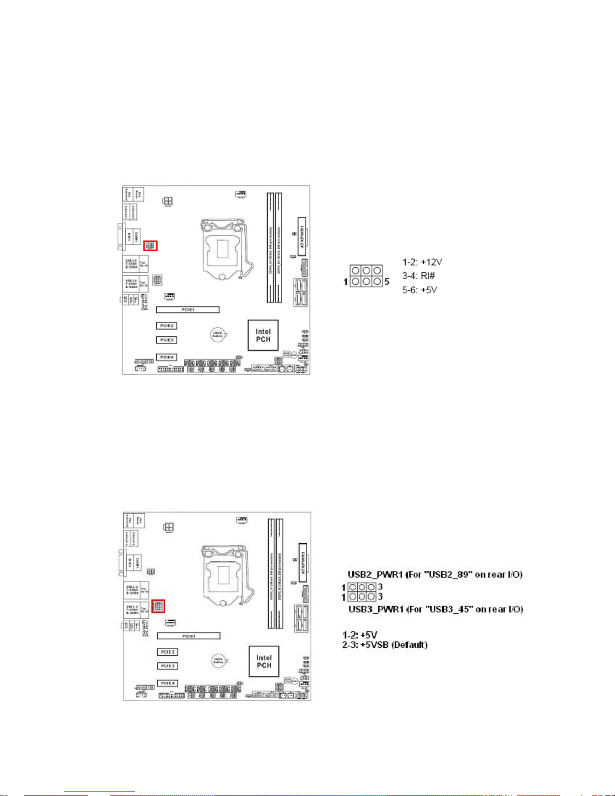
1.10 Jumpers
1.10.1 COM1 Pin#9 Power Setting Jumper: PWR_COM1
This header provides power selection for COM1 Pin#9.
1.10.2 Rear I/O USB Ports Power Setting Jumpers:
USB2_PWR1 (For USB2.0 Port “USB2_89”),
USB3_PWR1 (For USB3.0 Port “USB3_45”)
This header provides power selection for rear I/O USB ports.
35
Page 36
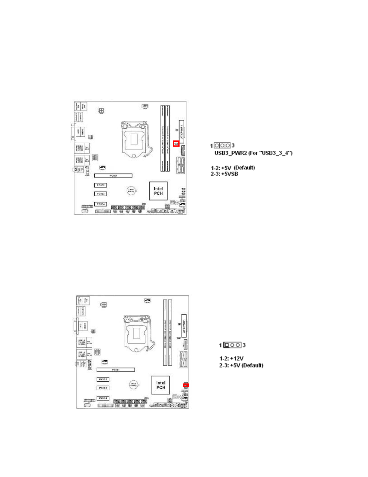
1.10.3 USB Power Setting Jumper for USB3.0 Header “USB3_3_4”:
USB3_PWR2
This header provides power selection for USB3.0 header “USB3_3_4”.
1.10.4 GPIO Input/ Output Power Select: JGPIO_PWR1
This header provides power selection for GPIO Input/Output.
36
Page 37
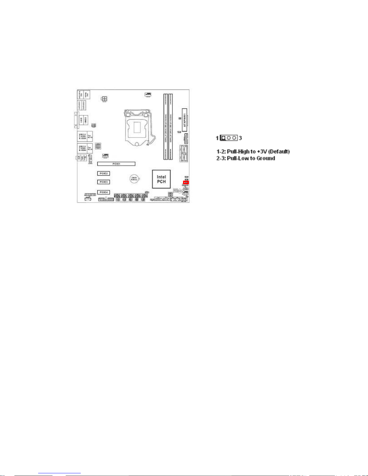
1.10.5 GPIO Signals Pull-High/ Pull-Low Selection: JGPIO_SET1
This header provides Pull-High/Pull-Low selection for GPIO header.
37
Page 38
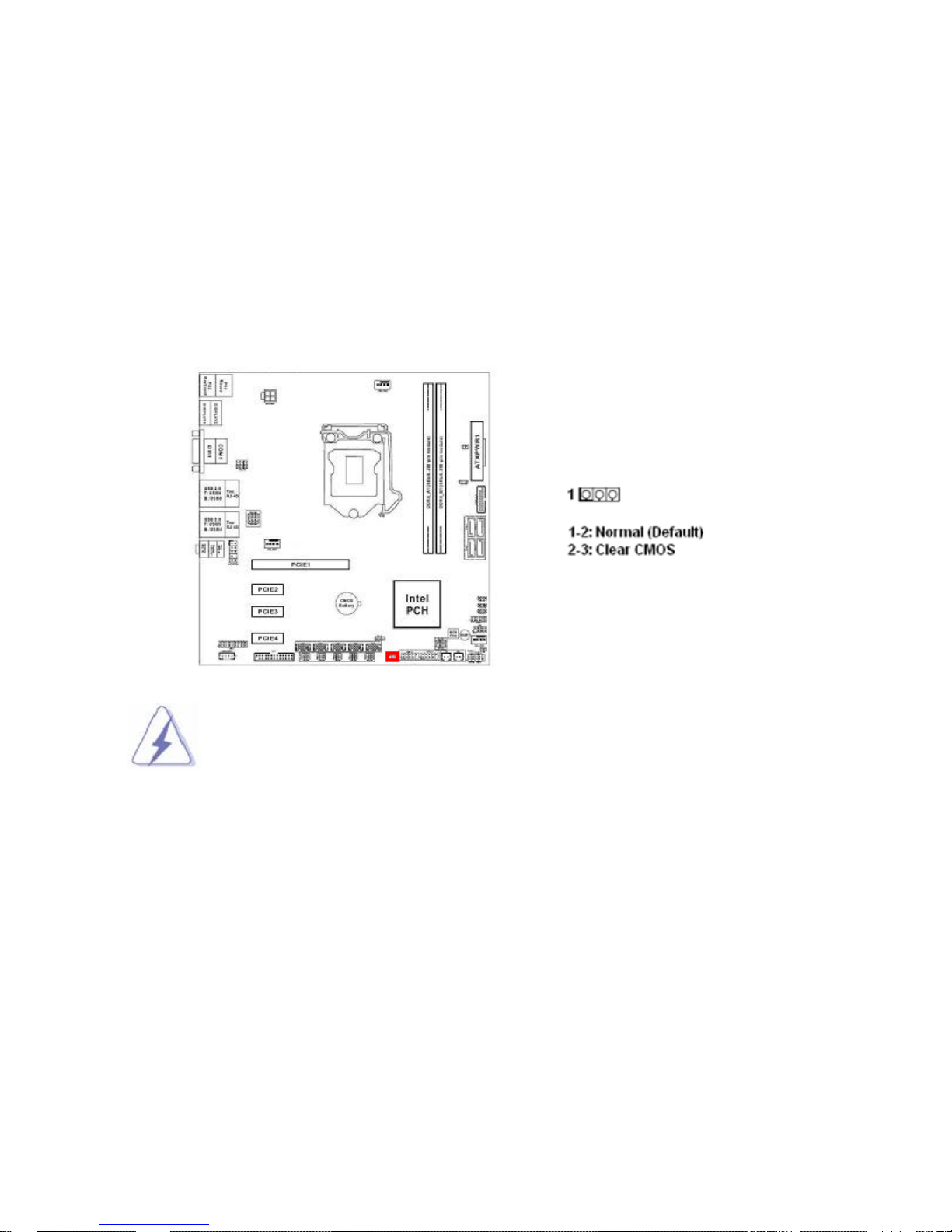
1.10.6 Clear CMOS Header: CLRMOS1
There is a CMOS RAM onboard that has the power supplied from an external battery to
maintain the registry settings of system configuration.
For normal state (default), the jumper is set on pin location 1 and 2.
To clear the CMOS, disconnect all power connections to mainboard first, then set the
CLRMOS1 jumper to pin location 2 and 3 for at least 30 seconds while the system is off,
then place the jumper back to pin 1-2 for normal operation.
Avoid clearing the CMOS while the system is ON; this may damage the mainboard.
38
Page 39
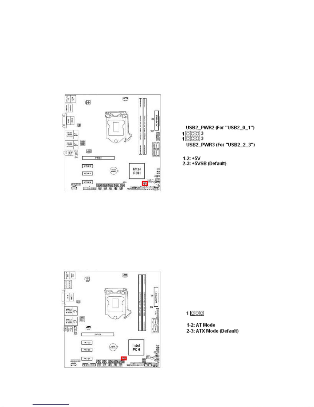
1.10.7 USB Ports Power Setting Jumpers:
USB2_PWR2 (For USB2.0 Port “USB2_0_1”),
USB2_PWR3 (For USB2.0 Port “USB2_2_3”)
These headers provide power selection for USB2.0 headers “USB 2_0_1” and “USB2_3_3”.
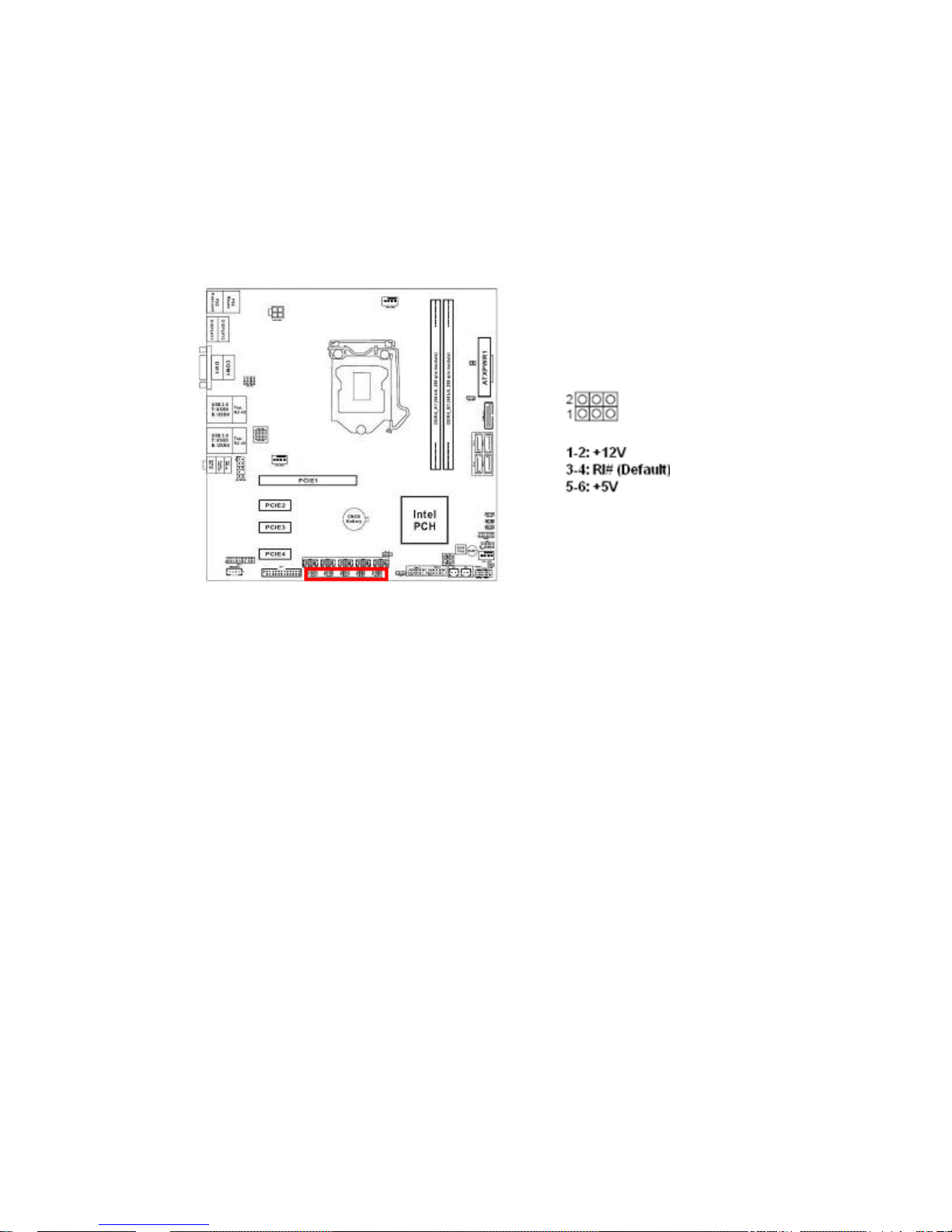
1.10.8 ATX/ AT Mode Select: PWR_JP1
This header provides the option to boot the system in the form of ATX mode (default) or AT
mode.
When the system is set in AT mode, the system power on/off will be controlled directly by the
power switch on power supply. And some of the power saving modes will not function as ATX
mode provided.
39
Page 40
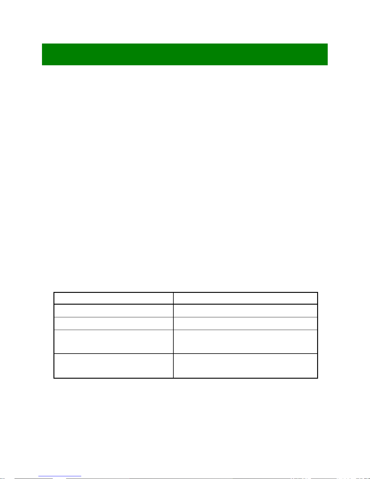
1.10.9 COM2/3/4/5/6 Pin#9 Power Setting Jumper:
PWR_COM2, PWR_COM3, PWR_COM4, PWR_COM5,
PWR_COM6
This header provides power selection for COM2,3, 4, 5, 6 Pin#9.
40
Page 41

1.11 The Expansion Slots
In the future, you may need to install expansion cards. The following sub-sections describe the
expansion slots and the expansion cards that they support.
Make sure to unplug the power cord before adding or removing expansion cards.
Fail to do so may cause injury and damage mainboard.
There are 4 PCI Express slots on this motherboard:
PCIE1 (PCIE x16 slot) is used for PCI Express x16, or PCI Express x4 cards.
PCIE2 (PCIE x1 slot) is used for PCI Express x1 cards.
PCIE3 (PCIE x1 slot) is used for PCI Express x1 cards.
PCIE4 (PCIE x1 slot) is used for PCI Express x1 cards.
1.11.1 Installation of Expansion Card
To install an expansion Card:
1. Before install the expansi on card, read the documentation that came with it and make the
necessary hardware setting for the card.
2. Remove the chassis cover (if the mainboard is installed in a chassis).
3. Remove the expansion slot bracket from the chassis on the slot that you intend to use. Keep
the screw for later use.
4. Align the card connector with the slot and press it firmly until the card is completely seated on
the slot.
5. Secure the card to the chassis with the screw that have been removed earlier (in step 3).
6. Place the chassis cover back on.
1.11.2 Setup An Expansion Card
After installing the expansion card, configure it by adjusting the software settings.
1. Turn on the system and change the BIOS settings if necessary.
2. Assign an IRQ to the card if necessary.
3. Install the software drivers for the expansion card.
41
Page 42
Chapter 2: Starting Up the System
2.1 Starting Up Your System
1. After all connections are made, close your computer case cover.
2. Be sure all the switches are off, and check that the power supply input voltage is set to the local
voltage, usually in-put voltage is 220V∼240V or 110V∼120V depending on your country’s voltage used.
3. Connect the power supply cord into the power supply located on the back of your system case
according to your system user’s manual.
4. Turn on your peripheral in following order:
a. Your monitor.
b. Other external peripheral (Printer, Scanner, External Modem etc…)
c. Your system power. For ATX power supplies, you need to turn on the power supply and press
the ATX power switch on the front side of the case.
5. The power LED on the front panel of the system case will light. The LED on the monitor may light up
or switch between orange and green after the system is on. If it complies with green standards or if it
is has a power standby feature. The system will then run power-on test. While the test are running,
the BIOS will alarm beeps or additional message will appear on the screen.
If you do not see any thing within 30 seconds from the time you turn on the power. The system may
have failed on power-on test. Recheck your jumper settings and connections or call your retailer for
assistance.
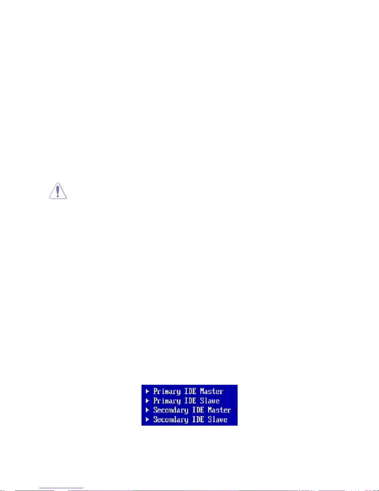
Beep Meaning
One short beep when displaying logo No error during POST
Long beeps in an endless loop No DRAM install or detected
One long beep followed by three short
beeps
High frequency beeps when system is
working
6. During power-on, press <Del> key to enter BIOS setup. Follow the instructions in BIOS SETUP.
7. If you wish to boot from a different bootable device other than the default arrangement under the BIOS,
Video card not found or video card memory bad
CPU overheated
System running at a lower frequency
you may press <F11> key during the system power-on (post); a menu with all detected bootable
42
Page 43

devices which are attached to the system will be displayed. Then you may select the desired first
bootable device from this menu.
8. Power off your computer: You must first exit or shut down your operating system before switch off
the power switch. If you use Windows Operating Systems, click “Start” button, click “Shut down” and
then click “Shut down the computer” The power supply should turn off after windows shut down.
43
Page 44

Chapter 3: BIOS Setup
3.1 BIOS Flash Related Procedure
1. After the BIOS is flashed, shut down the system.
2. Disconnect all power connections from power supply to the mainboard.
3. Clear the CMOS by relocate the jumper connector on header “CLRMOS” from pin 1-2 to pin 2-3
for at least 30 seconds.
4. Relocate the jumper connector on header “CLRMOS” from pin 2-3 back to pin 1-2.
4. Reconnect all power connections from power supply to the mainboard.
5. When the system is booting at first time after the new BIOS is flashed, it is recommended to
enter the BIOS; load the option “Load Optimized Defaults”, and then “Save and Exit Setup”.
IF ANY OF THE STEPS DESCRIBED ABOVE IS NOT FOLLOWED, IT MAY CAUSE THE
FLASHED BIOS NOT FUNCTION PROPERLY.
3.2 Introducing BIOS
The BIOS is a program located on a Flash Memory on the motherboard. This program is a bridge
between motherboard and operating system. When you start the computer, the BIOS program gains
control. The BIOS first operates an auto-diagnostic test called POST (power on self test) for all the
necessary hardware, it detects the entire hardware device and configures the parameters of the hardware
synchronization. Only when these tasks are completed, the BIOS then transfer the control of the
computer to operating system (OS). Since the BIOS is the only channel for hardware and software to
communicate, it is the key factor for system stability, and in ensuring that your system performance as its
best.
In the BIOS Setup main menu, you can see several options. We will explain these options step by step in
the following pages of this chapter, but let us first see a short description of the function keys you may use
here:
• Press <Esc> to quit the BIOS Setup.
• Press ↑↓←→ (up, down, left, right) to choose, in the main menu, the option you want to confirm or
to modify.
• Press <F10> when you have completed the setup of BIOS parameters to save these parameters
and to exit the BIOS Setup menu.
44
Page 45
• Press Page Up/Page Down or +/– keys when you want to modify the BIOS parameters for the active
option.
3.3 Entering BIOS Setup Menu
Power on the computer and by pressing <DEL> immediately allows you to enter BIOS Setup Menu.
If you are not able to enter the BIOS menu but you still wish to enter Setup, restart the system to try again
by turning it OFF then ON or pressing the “RESET” button on the system case. You may also restart by
simultaneously pressing <Ctrl>, <Alt> and <Delete> keys.
The items under each BIOS category described in this chapter are under continuous
update for better system performance. Therefore, the description may be slightly
different from the latest BIOS and should be held for reference only.
3.4 Getting Help
Main Menu
The main menu lists the setup functions you can make changes to. You can use the arrow keys to select
the item. The on-line description of the highlighted setup function is displayed at the bottom of the screen.
Sub- Menu
If you find a right pointer symbol (as shown in the picture below) appears to the left of certain fields that
means a sub-menu can be launched from this field. A sub-menu contains additional options for a field
parameter. You can use arrow keys to highlight the field and press <Enter> to call up the sub-menu. Then
you can use the control keys to enter values and move from field to field within a sub-menu. If you want to
return to the main menu, just press the <ESC>.
General Help <F1>
45
Page 46
The BIOS setup program provides a General Help screen. You can call up this screen from any menu by
simply pressing <F1>. The Help screen lists the appropriate keys to use and the possibl e sel ection s for the
highlighted item. Press <Esc> to exit the Help screen.
3.4.1 UEFI Menu Bar
The top of the screen has a menu bar with the following selections:
Main To set up the system time/date information
Advanced To set up the advanced UEFI features
H/W Monitor To display current hardware status
Security To set up the security features
Boot To set up the default system device to locate and load the Operating System
Exit To exit the current screen or the UEFI SETUP UTILITY
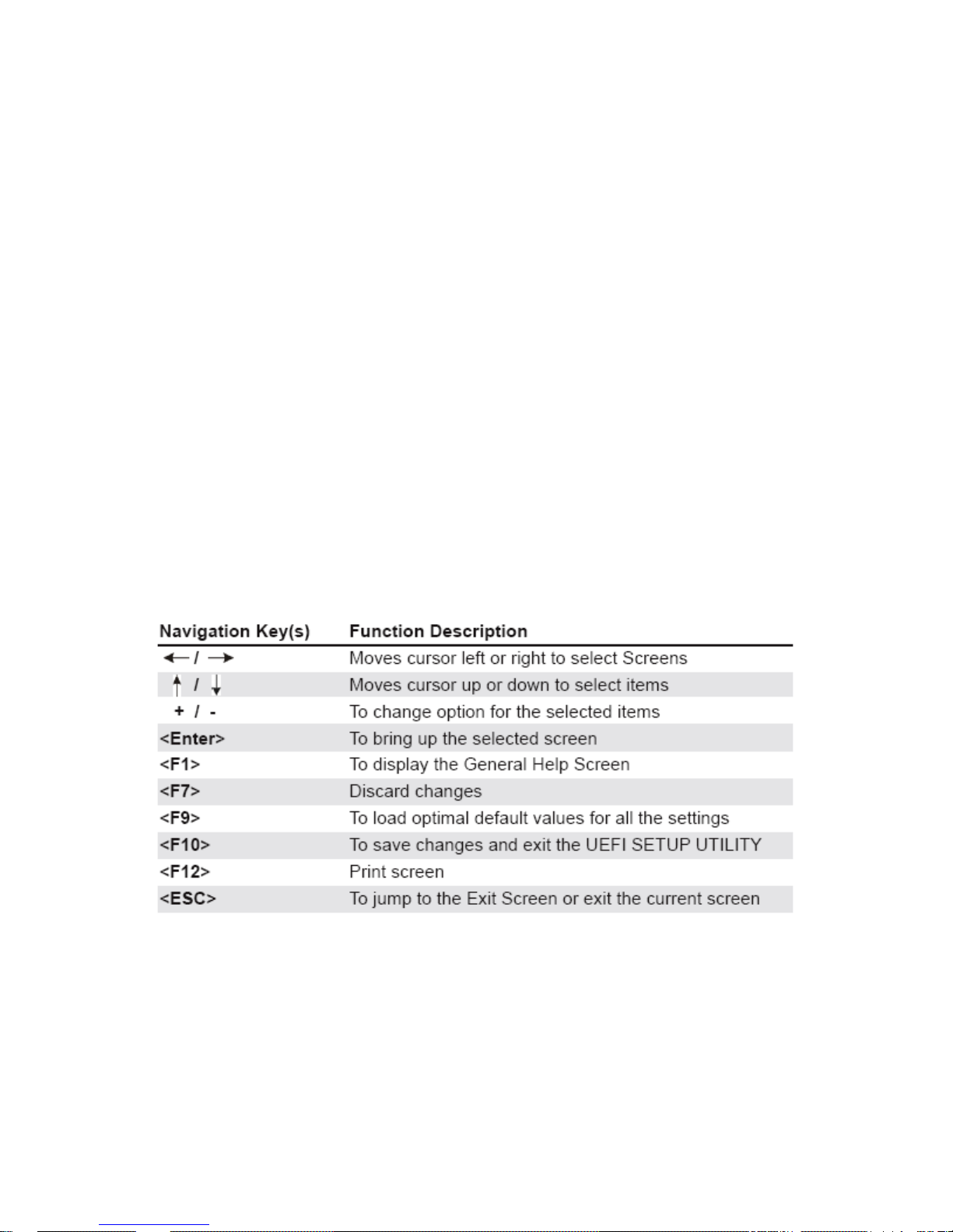
3.4.2 Navigation Keys
Please refer to the table below for the function description of navigation keys.
46
Page 47
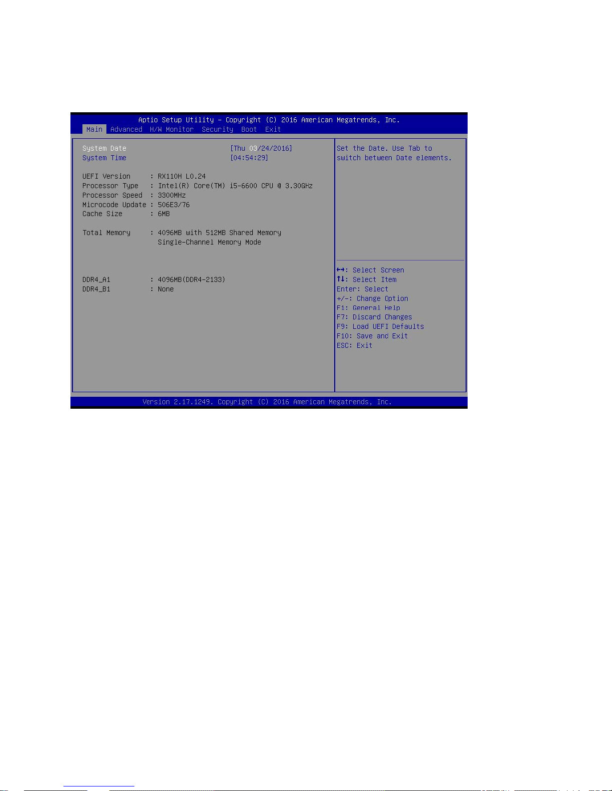
3.5 Main Screen
When you enter the UEFI SETUP UTILITY, the Main screen will appear and display the system overview.
47
Page 48
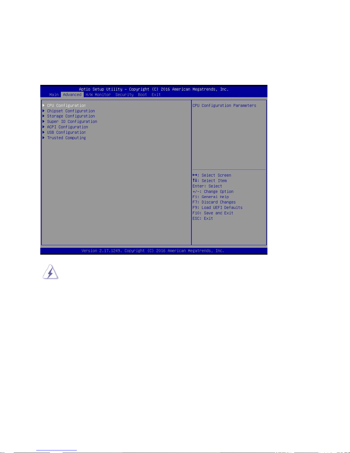
3.6 Advanced Screen
In this section, you may set the configurations for the following items: CPU Configuration, Chipset
Configuration, Storage Configuration, Super IO Configuration, ACPI Configuration, USB Configuration and
Trusted Computing.
Setting wrong values in this section may cause the system not function properly.
48
Page 49
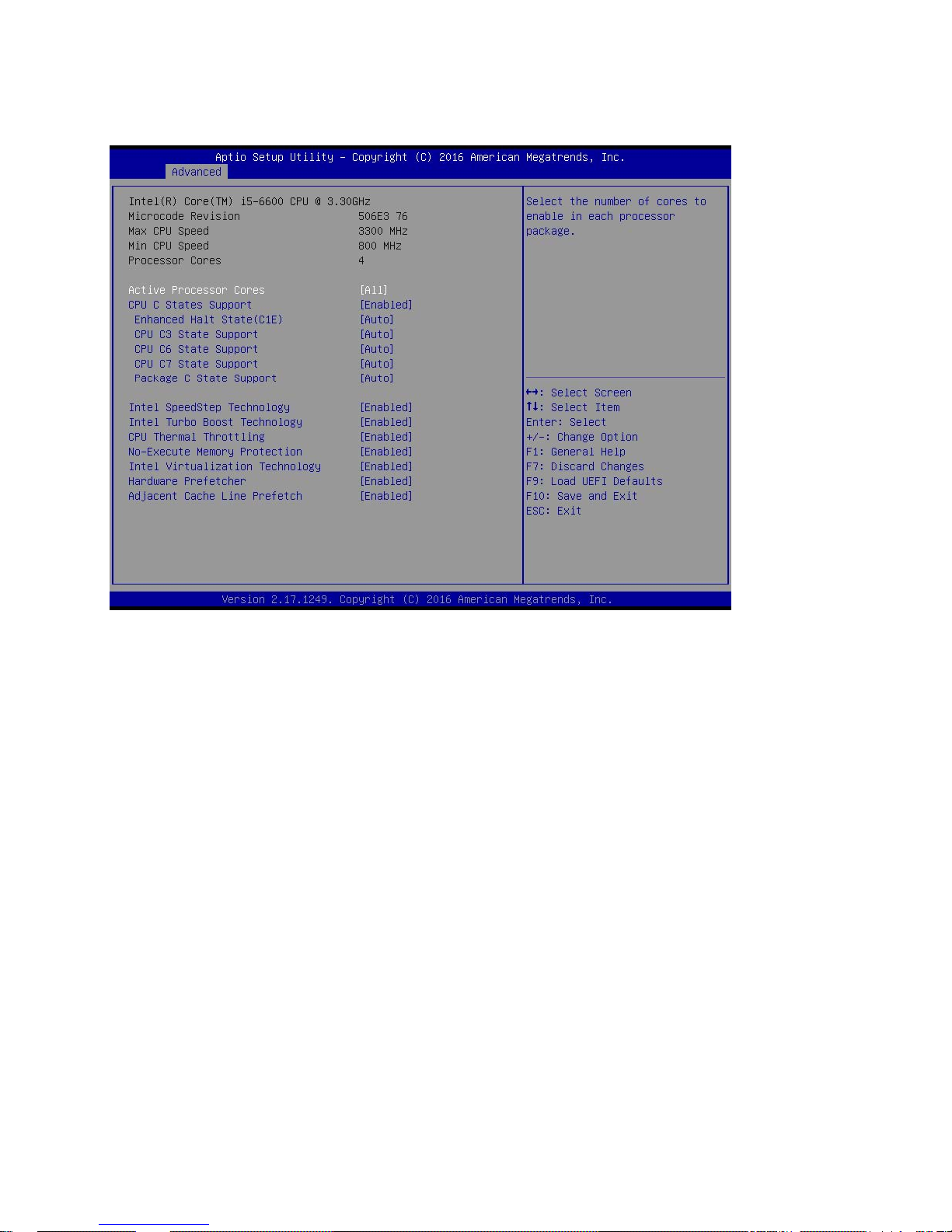
3.6.1 CPU Configuration
Active Processor Cores
Use this item to select the number of cores to enable in each processor package. The default value
is [All].
CPU C States Support
Enable CPU C States Support for power saving. It is recommended to keep C3, C6 and C7 all
enabled for better power saving.
Enhanced Halt State (C1E)
Enable Enhanced Halt State (C1E) for lower power consumption.
CPU C3 State Support
Use this to enable or disable CPU C3 (ACPI C2) report to OS.
CPU C6 State Support
Use this to enable or disable CPU C6 (ACPI C3) report to OS.
49
Page 50

CPU C7 State Support
Use this to enable or disable CPU C7 (ACPI C7) report to OS.
Package C State Support
Selected option will program into C State package limit register. The
default value is [Auto].
Intel SpeedStep Technology
Intel SpeedStep technology is Intel’s new power saving technology. Processors can switch
between multiple frequencies and voltage points to enable power saving. The default value is
[Enabled]. Configuration options:
[Enabled] and [Disabled]. If you install Windows® 8 / 8.1 and want to enable this function, please
set this item to [Enabled]. This item will be hidden if the current CPU does not support Intel
SpeedStep technology.
Please note that enabling this function may reduce CPU voltage and lead to system
stability or compatibility issues with some power supplies. Please set this item to
[Disabled] if above issues occur.
Intel Turbo Boost Technology
Intel Turbo Boost Technology enables the processor to run above its base operating frequency
when the operating system requests the highest performance state.
CPU Thermal Throttling
You may select [Enabled] to enable CPU internal thermal control
mechanism to keep the CPU from overheating.
No-Execute Memory Protection
No-Execution (NX) Memory Protection Technology is an enhancement
to the IA-32 Intel Architecture. An IA-32 processor with “No Execute (NX) Memory Protection” can
prevent data pages from being used by malicious software to execute codes. This option will be
hidden if the current CPU does not support No-Excute Memory Protection.
50
Page 51

Intel Virtualization Technology
When this option is set to [Enabled], a VMM (Virtual Machine Architecture) can utilize the additional
hardware capabilities provided by Vanderpool Technology. This option will be hidden if the installed
CPU does not support Intel Virtualization Technology.
Hardware Prefetcher
Use this item to turn on/off the MLC streamer prefetcher.
Adjacent Cache Line Prefetch
Use this item to turn on/off prefetching of adjacent cache lines.
51
Page 52
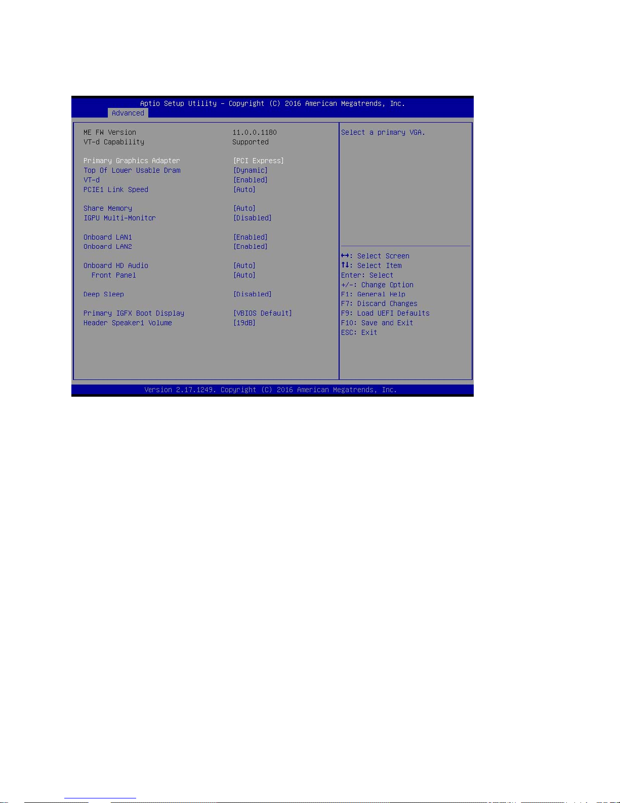
3.6.2 Chipset Configuration
Primary Graphics Adapter
This allows you to select [Onboard] or [PCI Express] as the boot graphic adapter priority. The
default value is [PCI Express].
Top of Lower Usable Dram
The default value is [Dynamic].
VT-d
Use this to enable or disable Intel® VT-d technology (Intel® Virtualization Technology for Directed
I/O). The default value of this feature is [Disabled].
PCIE1 Link Speed
Select the link speed for PCIE1.
Share Memory
Configure the size of memory that is allocated to the integrated graphics processor when the
system boots up.
52
Page 53

IGPU Multi-Moniter
This allows you to enable or disable IGPU Multi-Moniter. The default value
is [Enabled]. If you install the PCI Express card under Windows® XP / VistaTM OS, please disable
this option.
Onboard LAN 1
This allows you to enable or disable the Onboard LAN 1 feature.
Onboard LAN 2
This allows you to enable or disable the Onboard LAN 2 feature.
Onboard HD Audio
Select [Auto], [Enabled] or [Disabled] for the onboard HD Audio feature.
Front Panel
Select [Auto] or [Disabled] for the onboard HD Audio Front Panel.
Deep Sleep
Mobile platforms support Deep S5 in DC only and desktop platforms support Deep S5 in AC only.
The default value is [Disabled].
Primary IGFX Boot Display
Select a primary display output.
Header Speaker1 Volume
Select the header speaker1 volume.
53
Page 54
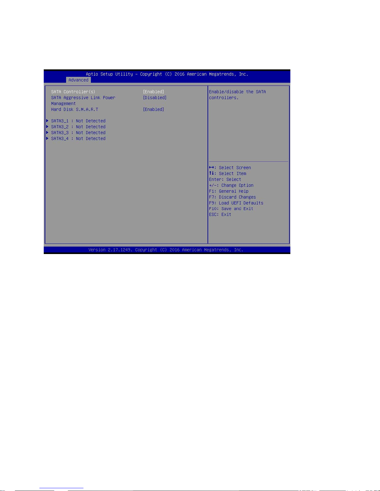
3.6.3 Storage Configuration
SATA Controller(s)
Use this item to enable or disable the SATA Controller feature.
SATA Aggressive Link Power Management
Use this item to configure SATA Aggressive Link Power Management.
Hard Disk S.M.A.R.T.
Use this item to enable or disable the S.M.A.R.T. (Self-Monitoring, Analysis, and Reporting
Technology) feature. Configuration options: [Disabled] and [Enabled].
54
Page 55
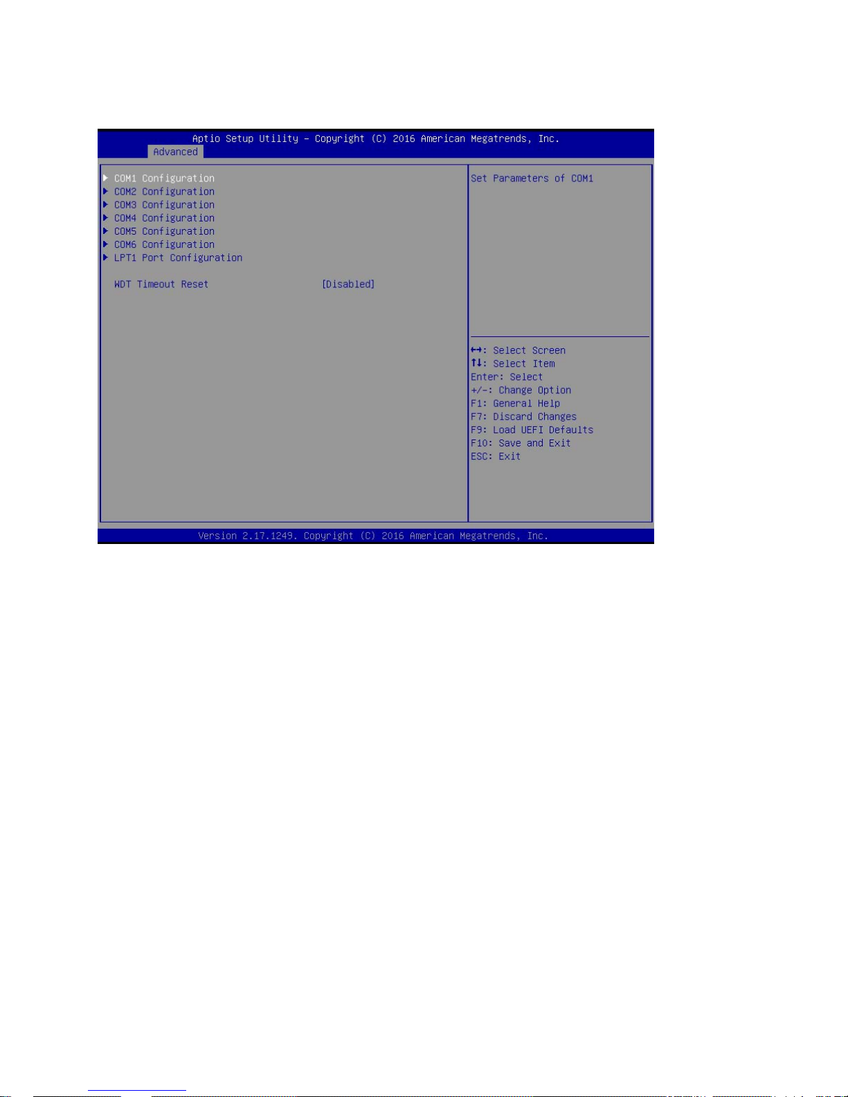
3.6.4 Super IO Configuration
COM1 Configuration
Use this to set parameters of COM1. Select COM1 port type: [RS232] (default), [RS422] or
[RS485].
COM2 Configuration
Use this to set parameters of COM2.
COM3 Configuration
Use this to set parameters of COM3.
COM4 Configuration
Use this to set parameters of COM4.
COM5 Configuration
Use this to set parameters of COM5.
COM6 Configuration
55
Page 56

Use this to set parameters of COM6.
LPT1 Port Configuration
Use this set parameters of the onboard parallel port.
WDT Timeout Reset
This allows users to enable/disable the Watch Dog Timer timeout to reset system. The default
value is [Disabled].
56
Page 57
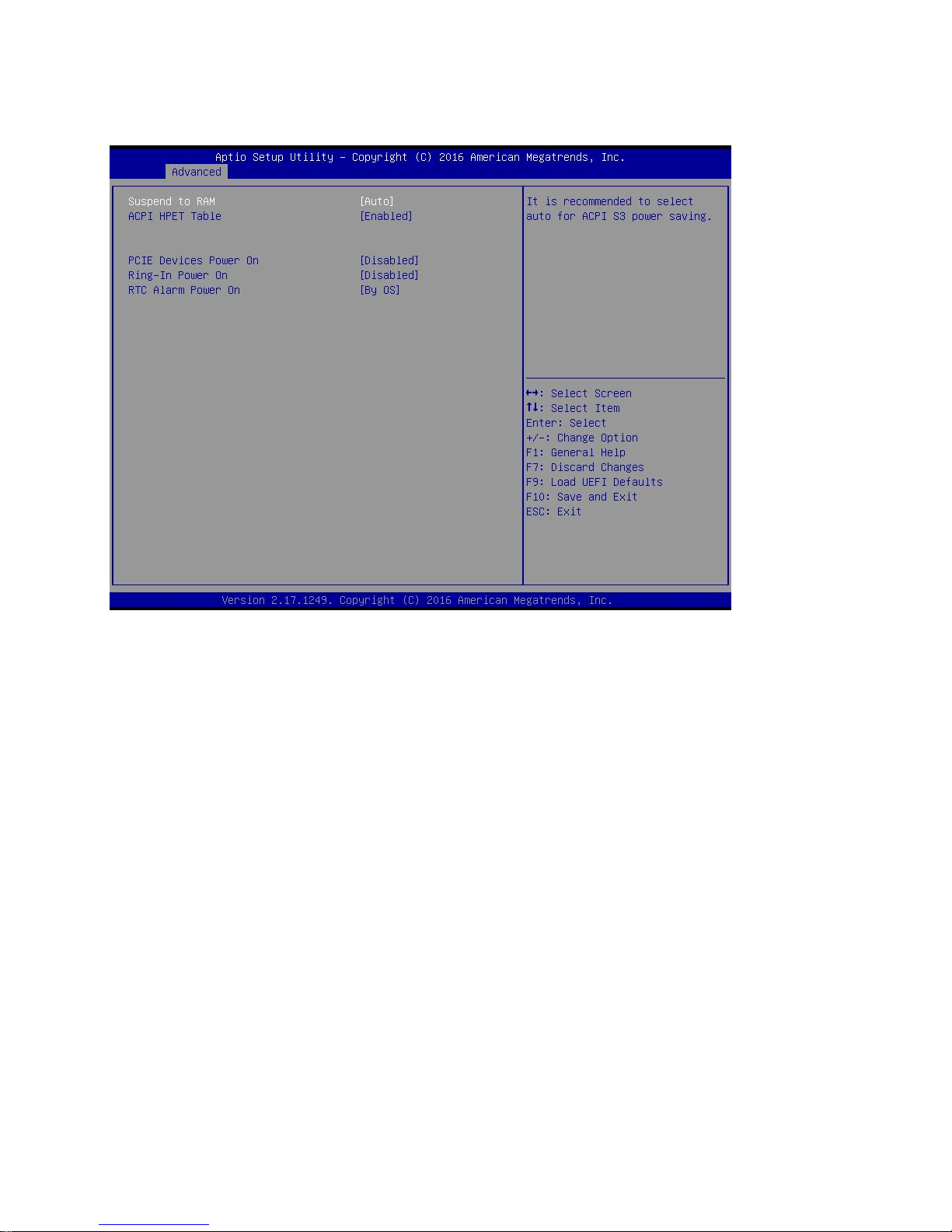
3.6.5 ACPI Configuration
Suspend to RAM
Use this item to select whether to auto-detect or disable the Suspend-to-RAM feature. Select [Auto]
will enable this feature if the installed OS supports it.
ACPI HPET Table
Use this item to enable or disable ACPI HPET Table. The default value is [Enabled]. Please set
this option to [Enabled] if you plan to use this
motherboard to submit Windows® certification.
PCIE Devices Power On
Use this item to enable or disable PCIE devices to turn on the system from the power-soft-off
mode.
Ring-In Power On
Allow the system to be waked up by onboard COM po rt modem Ring-In signals.
57
Page 58

RTC Alarm Power On
Use this item to enable or disable RTC (Real Time Clock) to power on the system.
58
Page 59
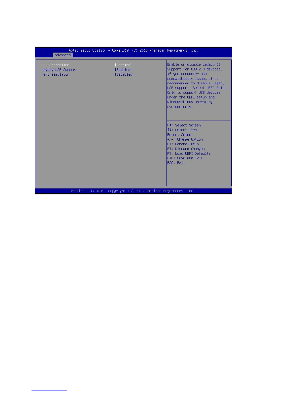
3.6.6 USB Configuration
USB Controller
Use this item to enable or disable the use of USB controller.
Legacy USB Support
Use this option to select legacy support for USB devices. There are four configuration options:
[Enabled], [Auto] and [UEFI Setup Only]. The default value is [Auto]. Please refer to below
descriptions for the details of these four options:
[Enabled] - Enables support for legacy USB.
[Auto] - Enables legacy support if USB devices are connected.
[UEFI Setup Only] - USB devices are allowed to use only under UEFI setup and Windows / Linux
OS.
PS/2 Simulator
The default value is [Disabled].
59
Page 60
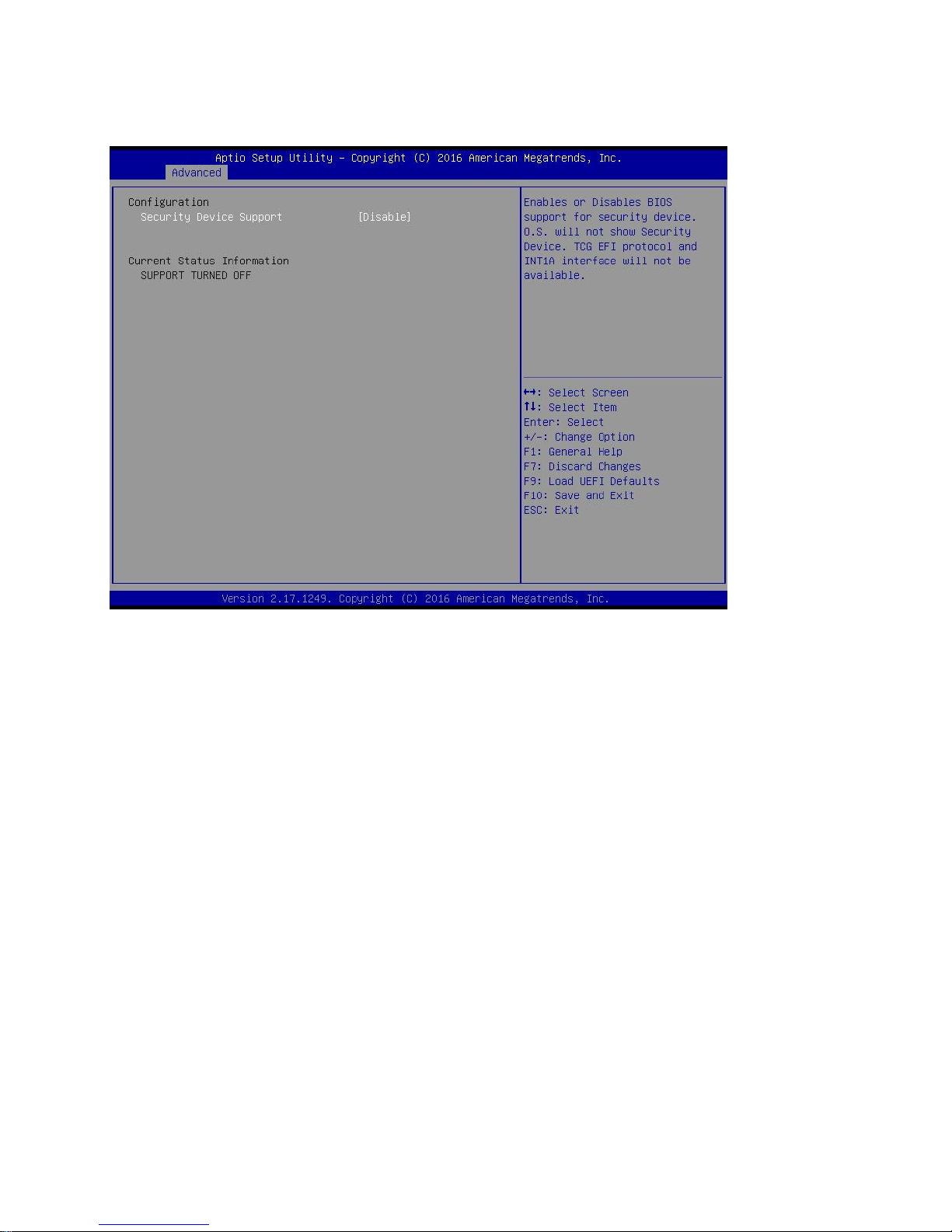
3.6.7 Trusted Computing
Security Device Support
Enable or disable BIOS support for security device.
60
Page 61
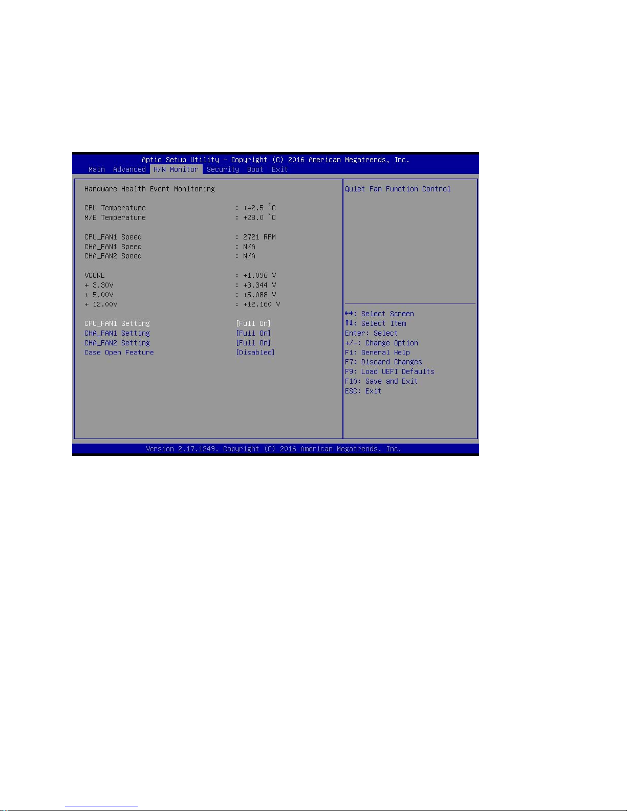
3.7 Hardware Health Event Monitoring Screen
In this section, it allows you to monitor the status of the hardware on your system, including the parameter s
of the CPU temperature, motherboard temperature, CPU fan speed, chassis fan speed, and the critical
voltage.
CPU_FAN1 Setting
This allows you to set CPU_FAN1’s speed. Configuration options: [Full On] and [Automatic Mode].
The default value is [Full On].
CHA_FAN1 Setting
This allows you to set CHA_FAN1’s speed. Configuration options: [Full On] and [Automatic Mode].
The default value is [Full On].
CHA_FAN2 Setting
This allows you to set CHA_FAN2’s speed. Configuration options: [Full On] and [Automatic Mode].
The default value is [Full On].
Case Open Feature
This allows you to enable or disable case open detection feature. The
default is value [Disabled].
61
Page 62

Clear Status
This option appears only when the case open has been detected. Use this
option to keep or clear the record of previous chassis intrusion status.
62
Page 63
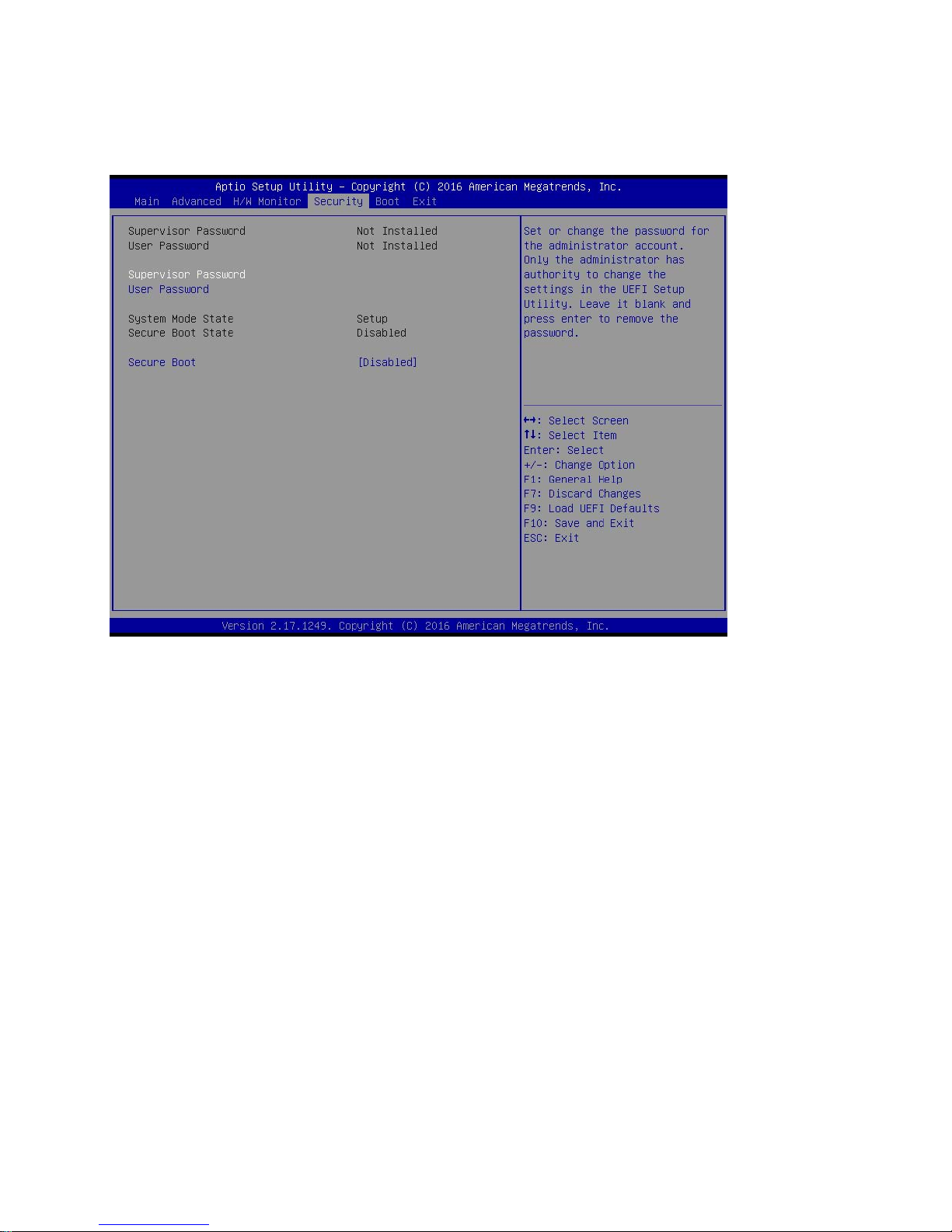
3.8 Security Screen
In this section, you may set, change or clear the supervisor/user password for the system.
Supervisor Password
Set or change the password for the administrator account. Only the administrator has authority to
change the settings in the UEFI Setup Utility. Leave it blank and press enter to remove the
password.
User Password
Set or change the password for the user account. Users are unable to change the settings in the
UEFI Setup Utility. Leave it blank and press enter to remove the password.
Secure Boot
Enable to support Windows 64-bit Secure Boot.
63
Page 64
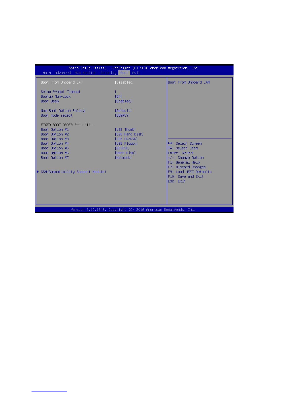
3.9 Boot Screen
In this section, it will display the available devices on your system for you to configure the boot settings and
the boot priority.
Boot From Onboard LAN
Use this item to enable or disable the Boot From Onboard LAN feature.
Setup Prompt Timeout
This shows the number of seconds to wait for setup activation key.
Bootup Num-Lock
If this item is set to [On], it will automatically activate the Numeric Lock function after boot-up.
Boot Beep
Select whether the Boot Beep should be turned on or off when the system boots up. Please note
that a buzzer is needed.
64
Page 65
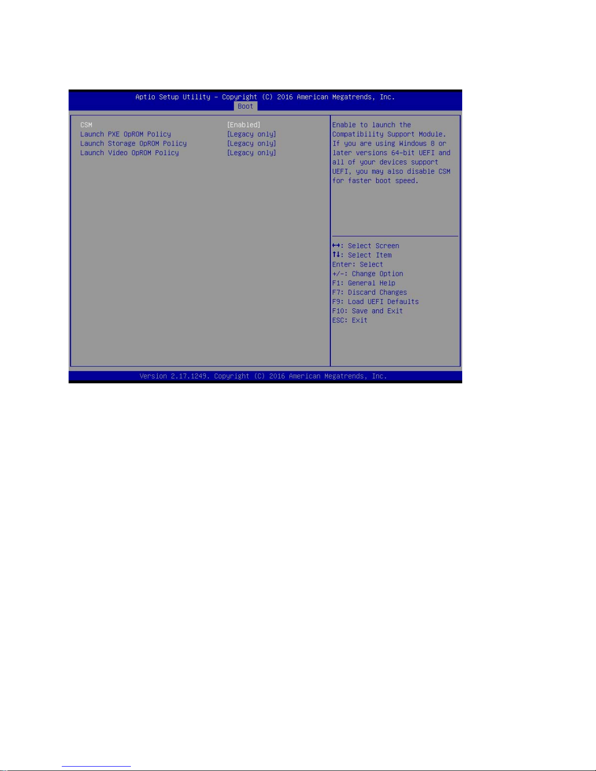
3.9.1 CSM (Compatibility Support Module)
CSM
Enable to launch the Compatibility Support Module. Please do not disable unless you’re running a
WHCK test. If you are using Windows® 8 64-bit and all of your devices support UEFI, you may also
disable CSM for faster boot speed.
Launch PXE OpROM Policy
Select UEFI only to run those that support UEFI option ROM only. Select Legacy only to run those
that support legacy option ROM only. Select Do not launch to not execute both legacy and UEFI
option ROM.
Launch Storage OpROM Policy
Select UEFI only to run those that support UEFI option ROM only. Select Legacy only to run those
that support legacy option ROM only. Select Do not launch to not execute both legacy and UEFI
option ROM.
Launch Video OpROM Policy
Select UEFI only to run those that support UEFI option ROM only. Select Legacy only to run those
65
Page 66

that support legacy option ROM only. Select Do not launch to not execute both legacy and UEFI
option ROM.
66
Page 67
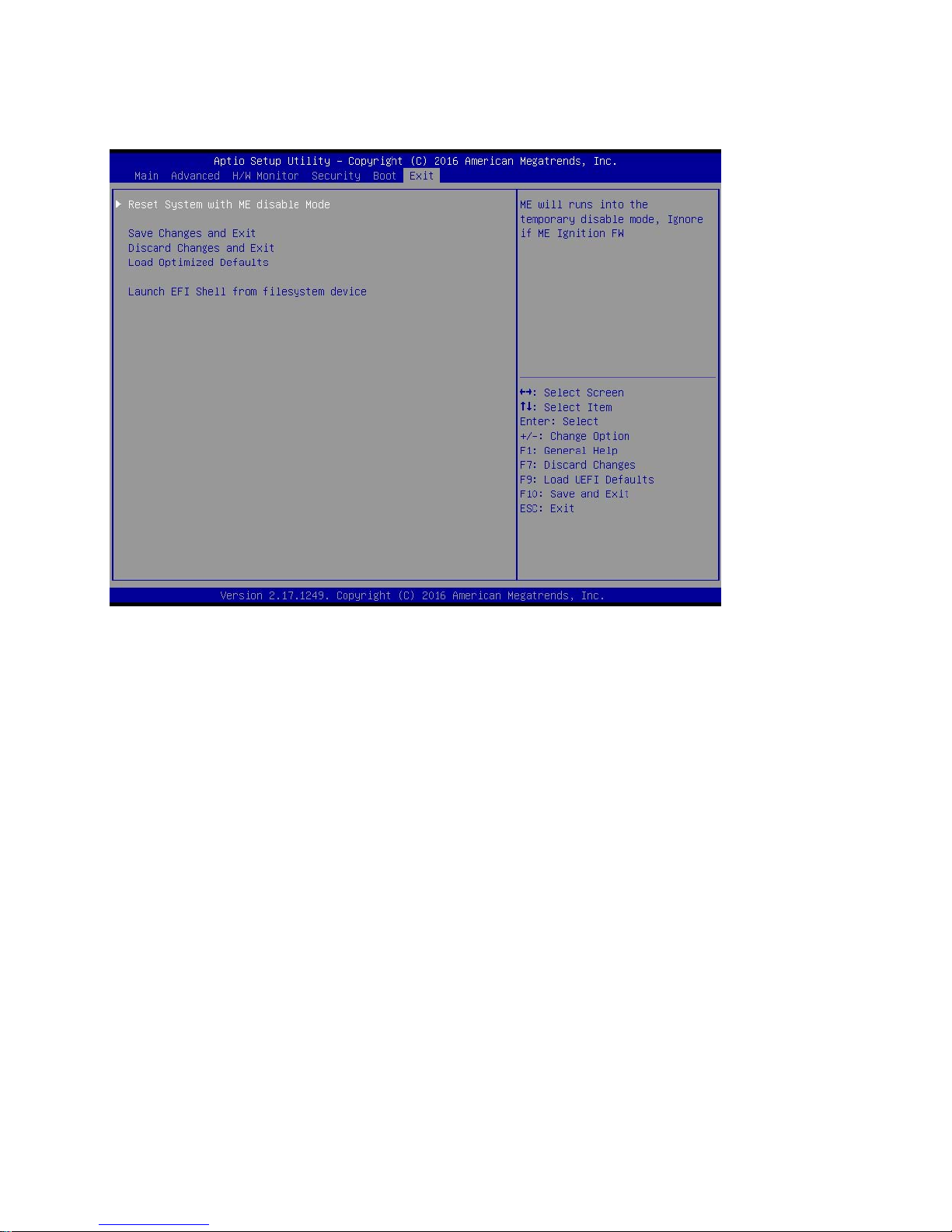
3.10 Exit Screen
Reset System with ME disable Mode
ME will run into the temporary disable mode. Ignore it if ME Ignition FW.
Save Changes and Exit
When you select this option, it will pop-out the following message, “Save configuration changes
and exit setup?” Select [OK] to save the changes and exit the UEFI SETUP UTILITY.
Discard Changes and Exit
When you select this option, it will pop-out the following message, “Discard changes and exit
setup?” Select [OK] to exit the UEFI SETUP UTILITY without saving any changes.
Load Optimized Defaults
Load optimized default values for all the setup questions.
Launch EFI Shell from filesystem device
Attempts to Launch EFI Shell application (Shell64.efi) from one of the available filesystem devices.
67
Page 68

Chapter 4: Application Note
Please read the following application notes before proceed with the system setup and/or OS
installation:
1. None
68
 Loading...