

Page 1

PPC Series
15LQFKDQG:LQFK Touch Panel PC
Quick Reference Guide
4
th
– 03 March, 201
Copyright Notice
Copyright © 2011 BCM Advanced Research, ALL RIGHTS RESERVED.
Page 2

Contents
1.1 Safety Precautions ................................................................................................3
1.2 Packing List ...........................................................................................................3
1.3 System Specifications ...........................................................................................4
1.4 System Overview..................................................................................................6
1.4.1 Front View.................................................................................................................... 6
1.4.2 Rear View..................................................................................................................... 7
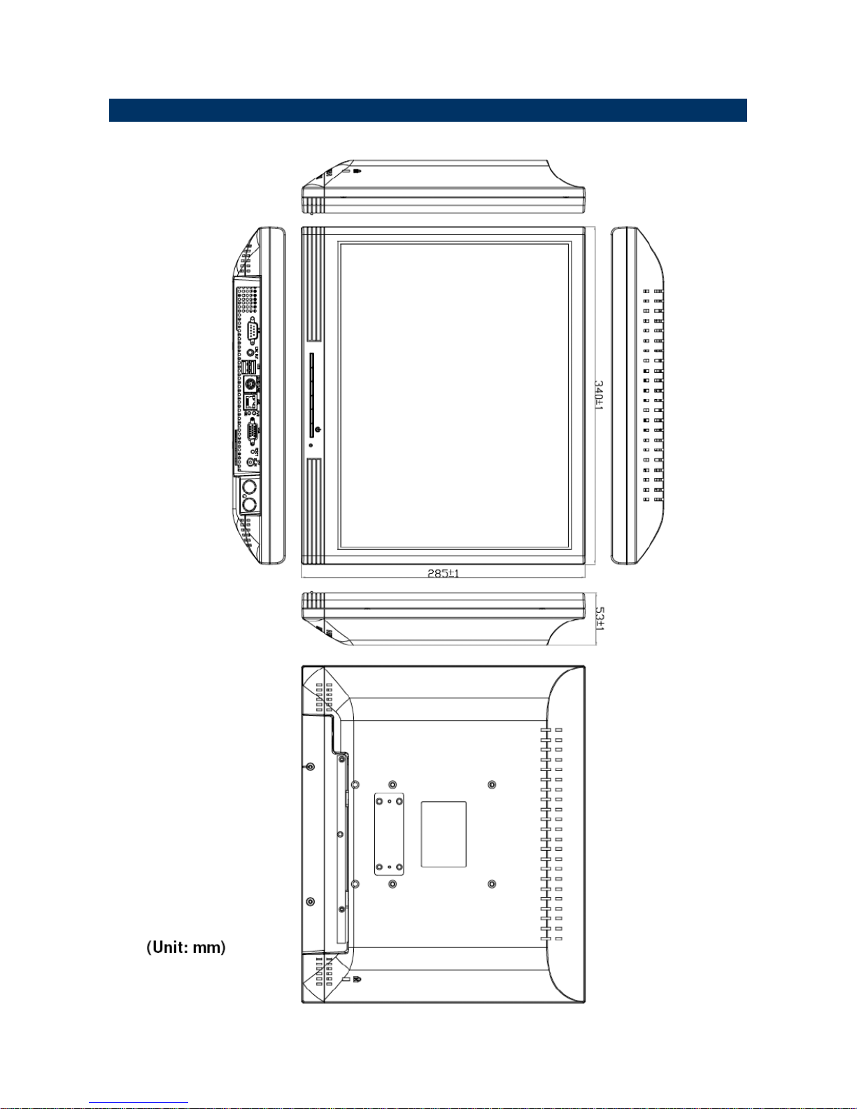
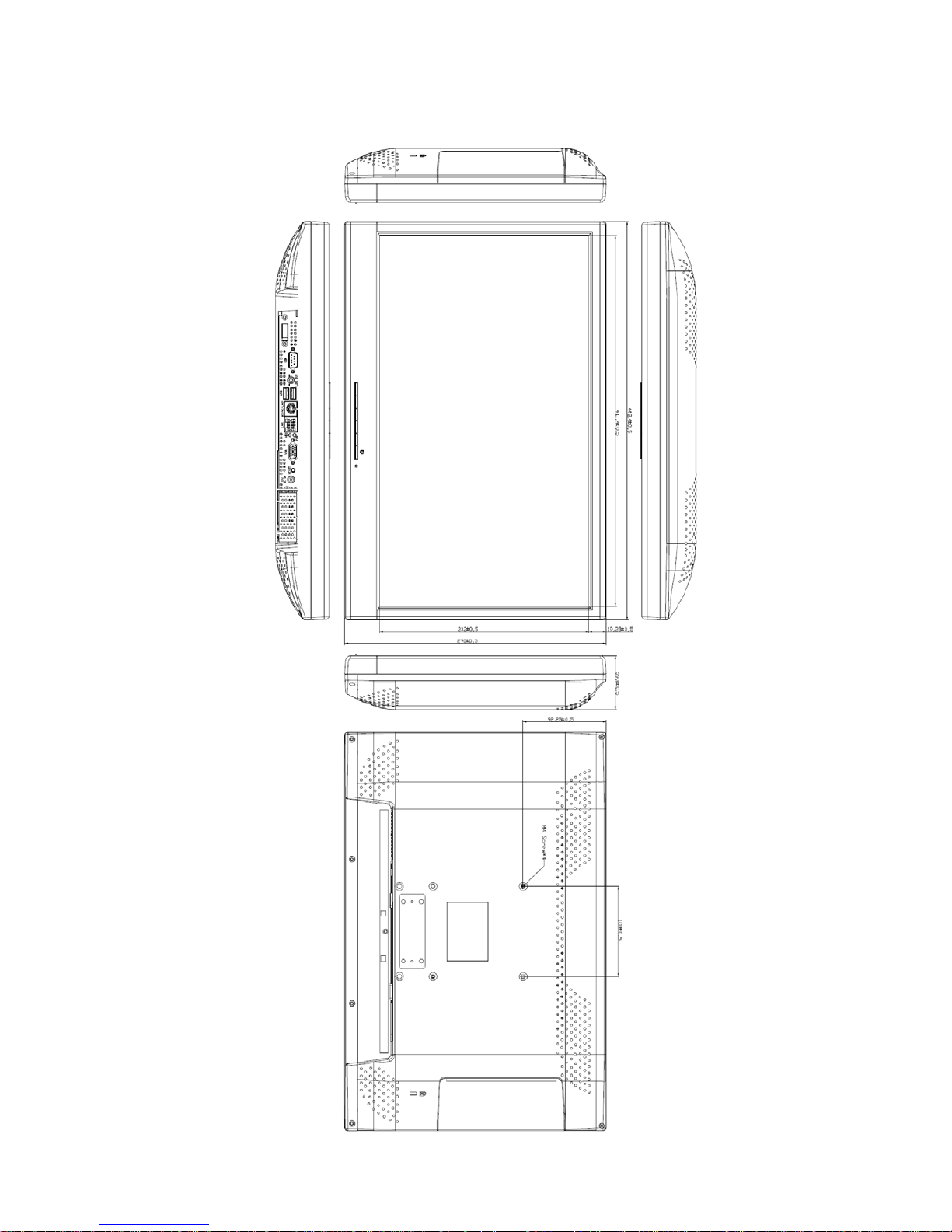
1.5 System Dimensions..............................................................................................8
1.5.1 PPC 15” Series ........................................................................................................... 8
1.5.2 PPC 18” Widescreen Series ....................................................................................... 9
2.1 Jumper and Connector Setting, Driver and BIOS Installing.................................10
2.2 Installing Hard Disk & Memory ............................................................................11
2.2.1 Install 2.5” HDD......................................................................................................................... 11
2.3 Installing Panel PC Stand....................................................................................14
2.4 Installing Optional MSR Module ..........................................................................15
Page 3
Quick Reference Guide
PPC Series Quick Reference Guide
3
1. Getting Started
1.1 Safety Precautions
Warning!
Always completely disconnect the power cord from your
chassis whenever you work with the hardware. Do not
make connections while the power is on. Sensitive
electronic components can be damaged by sudden power
surges. Only experienced electronics personnel should
open the PC chassis.
Caution!
Always ground yourself to remove any static charge before
touching the CPU card. Modern electronic devices are very
sensitive to static electric charges. As a safety precaution,
use a grounding wrist strap at all times. Place all electronic
components in a static-dissipative surface or static-shielded
bag when they are not in the chassis.
1.2 Packing List
z 1 x PPC 15”/18”W Series Panel PC
z 1 x CD/DVD-ROM contains the followings:
— Quick Reference Guide (this manual in PDF file)
— Ethernet driver and utilities
— VGA drivers and utilities
— Audio drivers and utilities
— WiFi drivers and utilities
— Touch controller drivers and utilities
z 1 x Power Adapter
z 1 x Stand for Panel PC (with 6 screws & 5 rubber-foot)
z 1 x MSR set with bracket (for optional MSR)
Page 4
PPC Series
4 PPC Series Quick Reference Guide
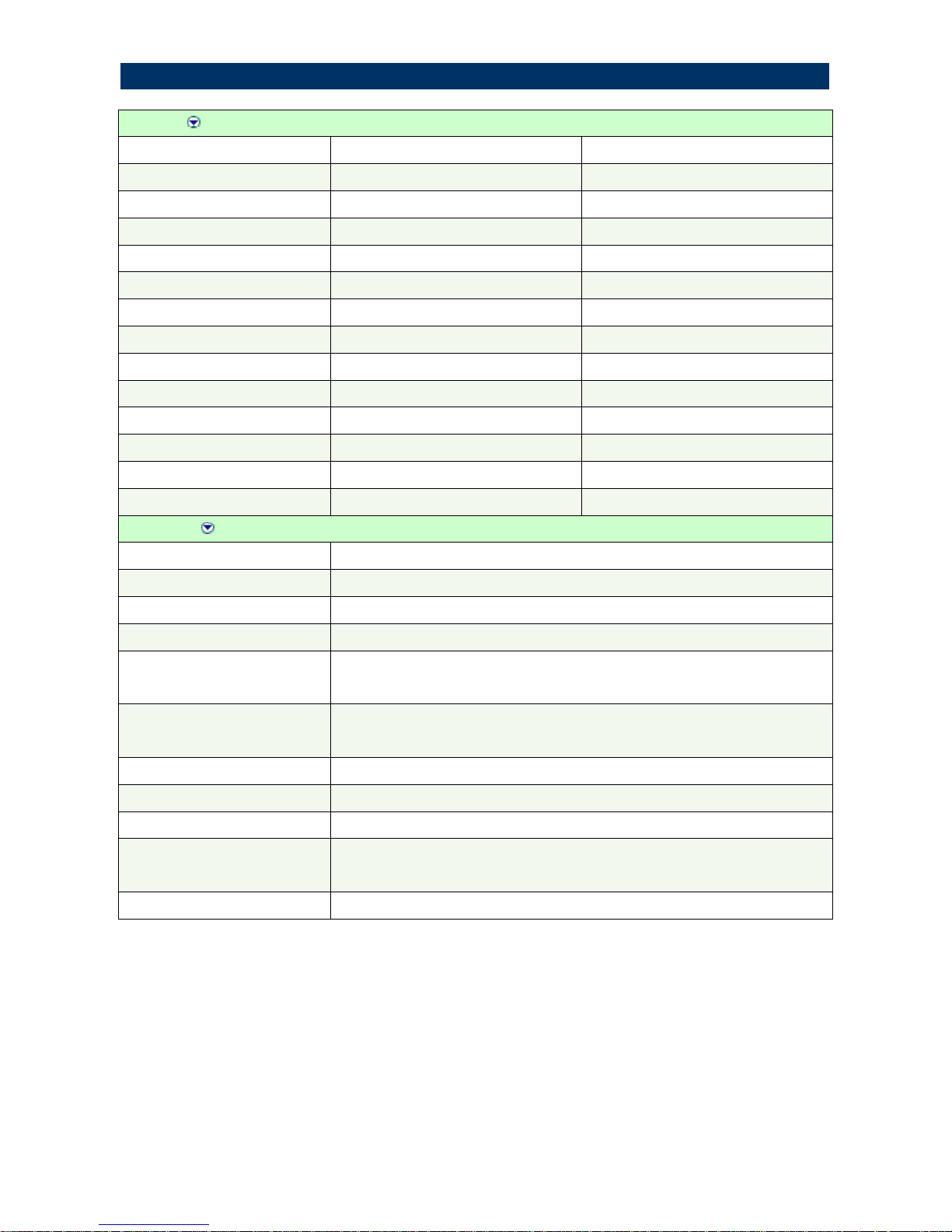
Panel
Specifications
PPC'PPC:'
LCD size
15", 4:3 18.5", 16:9
Display type
XGA TFT WXGA TFT
Resolution
1024 x 768 1366 x 768
Color
16.7M 16.7M
Pixel pitch
0.297mm(H) x 0.297mm(V) 0.300mm(H) x 0.300mm(V)
Luminance
300 cd/m² 300 cd/m²
Contrast ratio
700 1000
Viewing angle
70(U), 70(D), 75(L), 75(R) 80(U), 80(D), 85(L), 85(R)
Response time
8 ms 5 ms
Backlight
2 x CCFL 2 x CCFL
Touch Type
5 Wires resistive 5 Wires resistive
Touch Light Transmission
80% 80%
Touch Interface
USB USB
System
Board
EBM-PNV
CPU
Onboard Intel® Atom™ D525 Dual-Core 1.8 GHz CPU
System Chipset
Intel ICH8-M
I/O Chip
Winbond W83627DHG
Memory
Onboard 1 GB up to 2GB & one 204-pin SODIMM support up to 4 GB DDR3
800 SDRAM2
SSD
One CF socket by IDE secondary slave channel supports Type I / II Compact
Flash Card
HDD Drive Bay
One 2.5" SATA HDD
WiFi
Optional USB or Mini PCIe WiFi module
Watchdog Timer Reset: 1 ~ 255min. and 1sec. or 1min./step
H/W Status Monitor
Monitoring system temperature and voltage. Auto throttling control when
CPU overheats
Expansion Slot
One Mini PCIe slot
1.3 System Specifications
Page 5

Quick Reference Guide
PPC Series Quick Reference Guide 5
Rear Panel I/O
Serial Port 1 x RS-232
Ethernet 1 x RJ-45
VGA 1 x DB-15
Audio port 1 x Line out
USB 2 x USB 2.0
KB/MS 1 x PS/2 KB & MS
Speaker 2W x 2
Mechanical & Evironmental
System Fan
Passive Heat Sink
Color
Front & Rear panel Black (Plastics)
Mounting
Wall/Stand/VESA 100 mm X 100 mm
Power Input
100~250 Vdc/ 47~63 Hz
Power Output
+12 Vdc / 5 A (60W)
Operating Temperature
0 to 40°C (32 to 140°F )
Storage Temperature
-10°C to 50°C
Relative Humidity
0%~90% relative humidity, non-condensing
Dimensions
340 x 285 x 53 mm 372 x 324 x 53 mm
Weight
2.79 Kgs 3.79 Kgs
Page 6
PPC Series
6 PPC Series Quick Reference Guide
1.4 System Overview
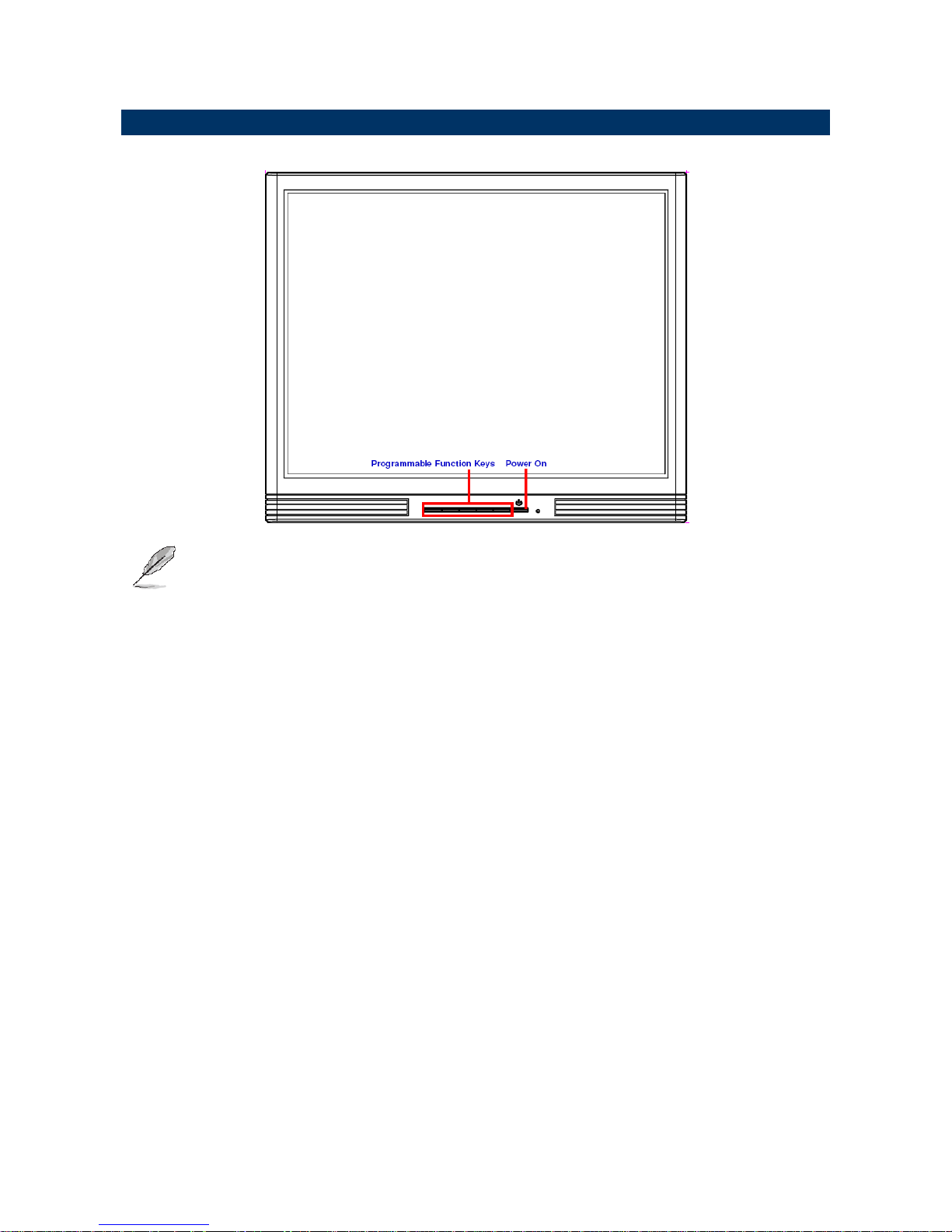
1.4.1 Front View
Note: The programmable function keys are available to be programmed by the
user, and they are unable to work unless programmed.
Page 7
Quick Reference Guide
PPC Series Quick Reference Guide
7
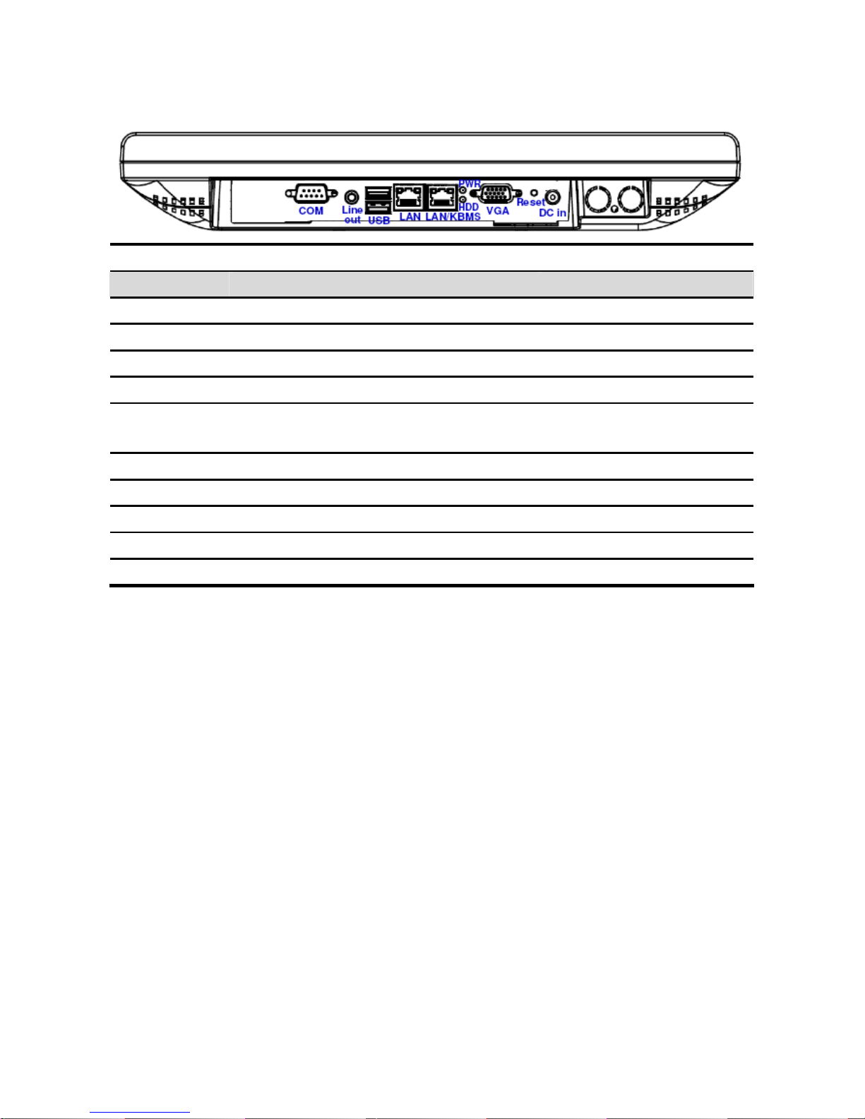
1.4.2 Rear View
Connectors
Label Function Note
COM
Serial port DB-9 male connector
DC in
DC-in power connector
HDD
HDD LED
LAN
10/100/1000Base-Tx Ethernet connector RJ-45
LAN/KBMS
10/100/1000Base-Tx Ethernet connector
or PS/2 keyboard & mouse
RJ-45 or 6-pin Mini DIN
LINE OUT
Line-out audio jack
PWR
Power LED
Reset
Rest button
USB
USB 2.0 connector
VGA
CRT connector DB-15 female connector
Page 8
PPC Series
8 PPC Series Quick Reference Guide
1.5 System Dimensions
1.5.1 PPC 15” Series
Page 9
PPC Series
9 PPC Series Quick Reference Guide
1.5.3 PPC 18” Widescreen Series
(Unit: mm)
Page 10

Quick Reference Guide
PPC Series Quick Reference Guide
10
1 Hardware
Configuration
2.1 Jumper and Connector Setting, Driver and BIOS
Installing
z Please refer to EBM-PNV Quick installation guide or user manual
Note: If you need more information, please visit our website:
http://www.EFPFRPFRP
Page 11
PPC Series
11 PPC Series Quick Reference Guide
2.2 Installing Hard Disk & Memory
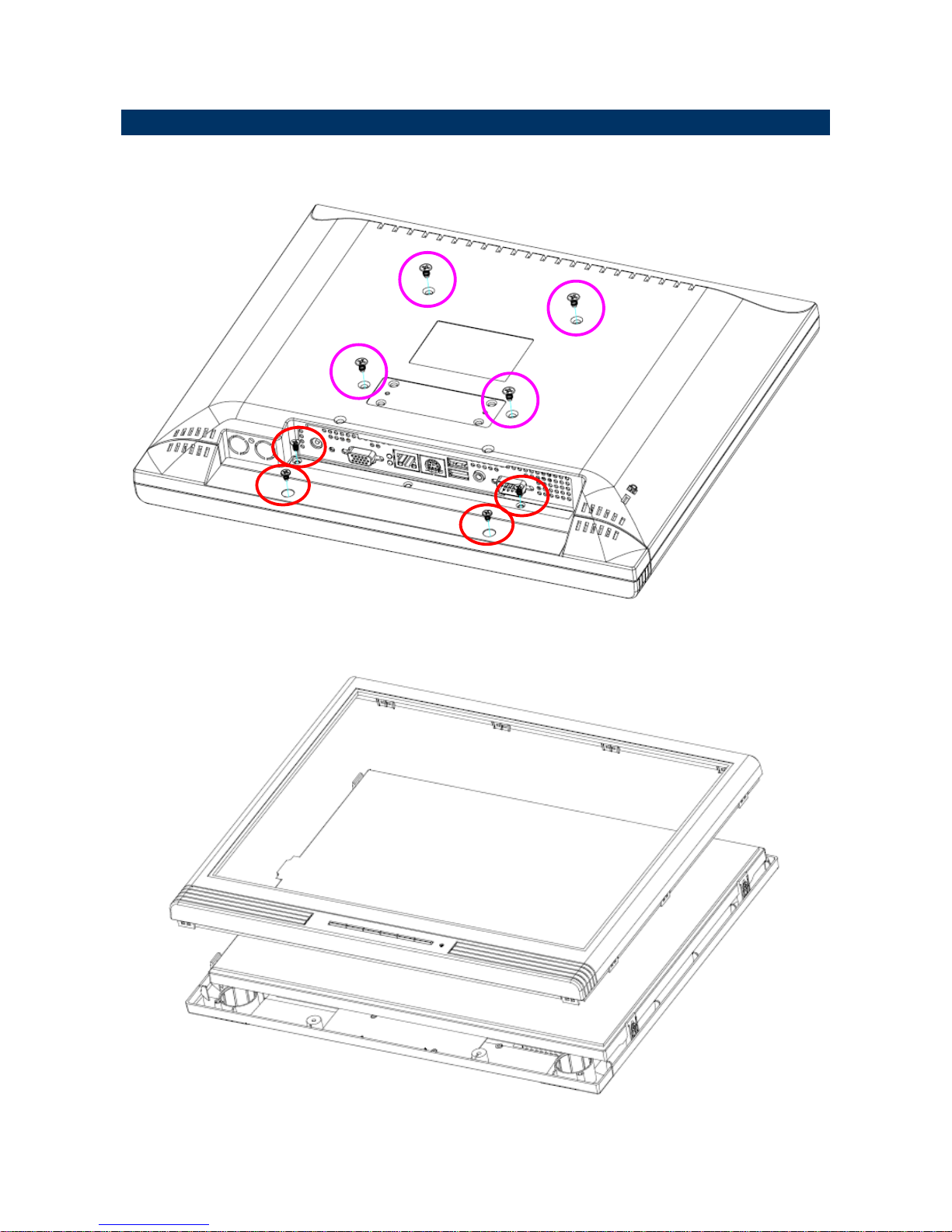
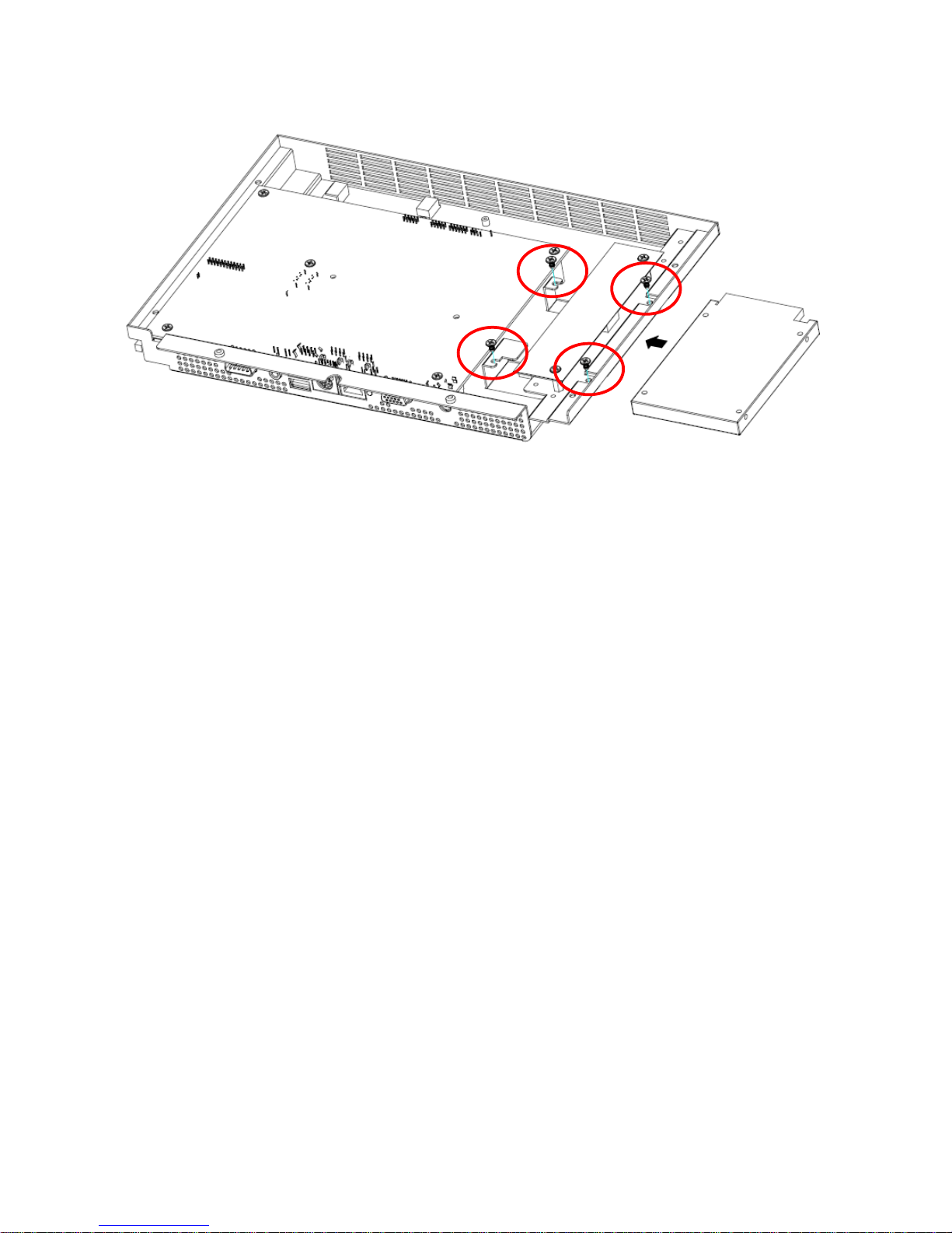
2.2.1 Install 2.5” HDD
Step 1. Unfasten 4 screws from the rear middle side and 4 screws from the rear bottom
side of PPC15-525D as above.
Step 2. Remove the front panel chassis.
Page 12
Quick Reference Guide
PPC Series Quick Reference Guide
12
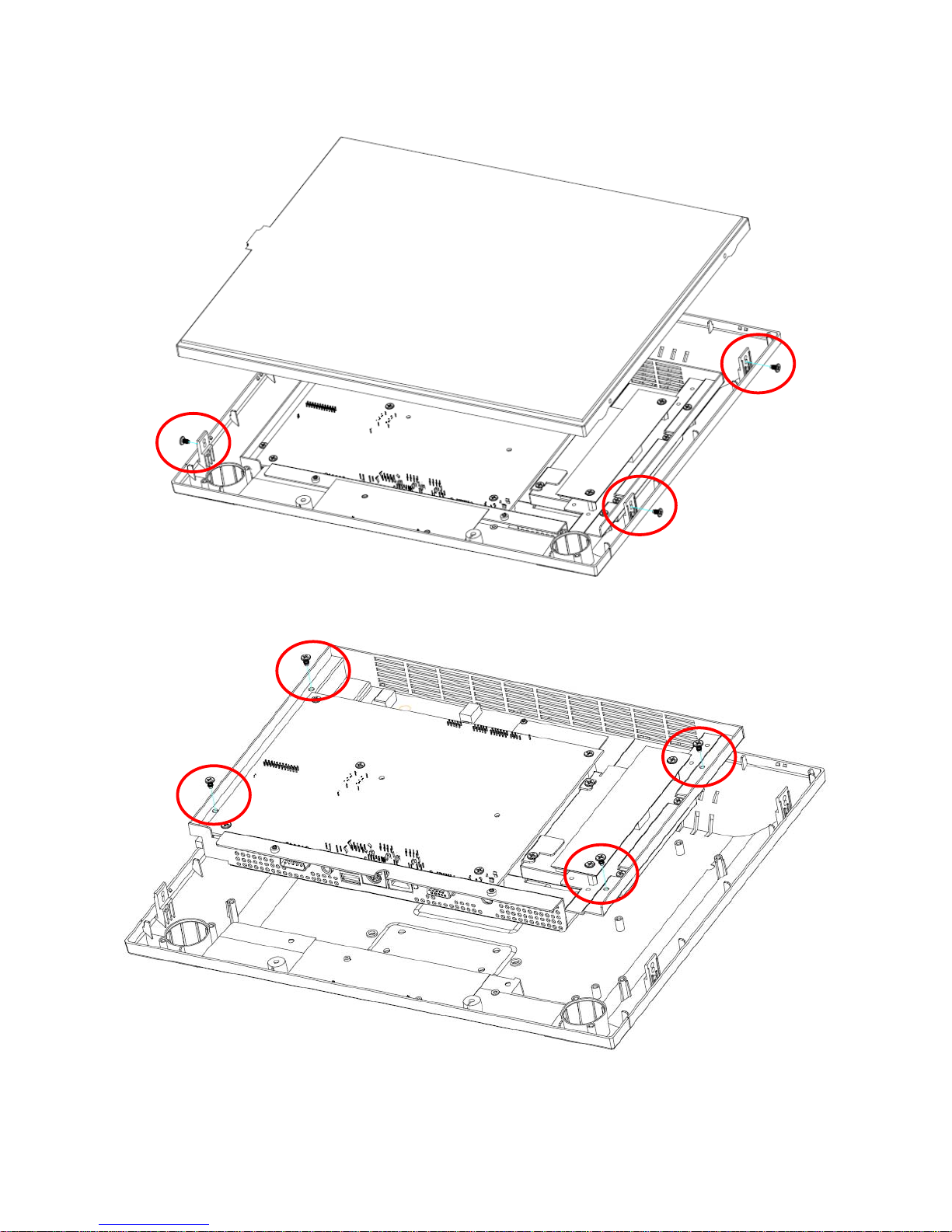
Step 3. Unlock 4 screws from the panel through the bottom chassis as above.
Step 4. Unfasten 4 screws from the metal bracket through the bottom chassis as indicated.
Page 13
PPC Series
13 PPC Series Quick Reference Guide
Step 5. Place the 2.5” HDD to the right position and fasten 4 screws to fix.
Step 6. Assemble the whole system as step 5, 4, 3, 2, 1.
Page 14
Quick Reference Guide
PPC Series Quick Reference Guide 14
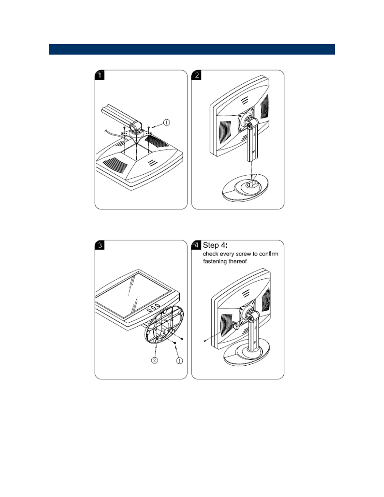
2.3 Installing Panel PC Stand
Step 1. Fasten 4 screws from the as indicated as above.
Step 2. Place the stand into the plastic plate.
Step 3. Stick the rubber-foot onto the backward of plastic plate and locked with 2 screws.
Page 15
PPC Series
15 PPC Series Quick Reference Guide
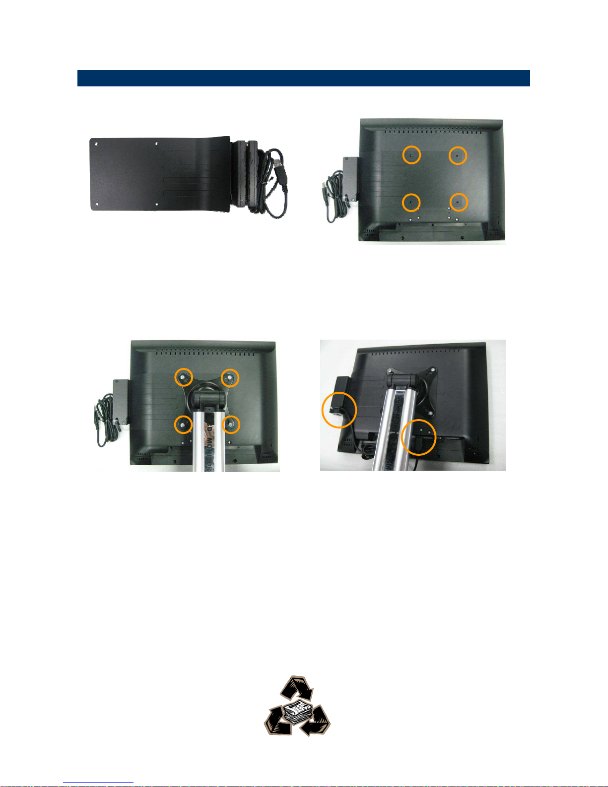
2.4 Installing Optional MSR Module
Step 1. Take out the MSR with bracket
module from the accessory box.
Step 2. Place the MSR module onto the
back of PPC15-525D and make sure
the holes meet the VESA
mountings.
Step 3. Put on the stand right above the
MSR module and have 4 screws
locked.
Step 4. Make the cable passed the hook of
the bracket, and then plug the USB
cable to the USB connector.
 Loading...