

Page 1

LITE-ON Technology Corp.
NA130 845PE Series ATX Mainboard
USER’S MANUAL
Intel® Pentium® 4 Processor Motherboard
Rev. 1.0
Page 2

Copyright
Copyright by LITE-ON, (LITE-ON Technology Corp). No part of this
manual may be reproduced or transmitted in any form without the expressed,
written permission of LITE-ON Technology Corp.
Trademarks
LITE-ON is a registered trademark of LITE-ON Technology Corp. Other
names, trademarks listed here are the property of their respective owners.
Notice
Although LITE-ON Technology has attempted to ensure the accuracy of the
content of this manual, it is possible that this document may contain technical
inaccuracies, typographical, or other errors. LITE-ON Technology assumes no
liability for any error in this publication, and for damages, whether direct,
indirect, incidental, consequential or otherwise, that may result from such error,
including, but not limited to loss of data or profits.
LITE-ON Technology provides this publication “as is” without warranty of
any kind, either express or implied, including, but not limited to implied
warranties of merchantability or fitness for a particular purpose.
The published information in the manual is subject to change without notice.
LITE-ON Technology reserves the right to make changes in the product
design, layout, and driver revisions without notification to its users.
2
Page 3

Chapter 1. Introduction ...................................................................7
1-1 Features and Specifications .................................................. 7
1. CPU… ....................................................................................................... 7
2. Chipset ......................................................................................................7
3. AGP….......................................................................................................7
4. Onboard IDE .............................................................................................7
5. Memory..................................................................................................... 7
6. Serial ATA .................................................................................................7
7. Audio.........................................................................................................8
8. USB 2.0..................................................................................................... 8
9. LAN… ......................................................................................................8
10. System BIOS ............................................................................................. 8
11. Internal Slots .............................................................................................8
12. Back Panel I/O ..........................................................................................8
13. Onboard I/O Interface ...............................................................................9
14. Miscellaneous............................................................................................ 9
15. Dimension .................................................................................................9
1-2 Layout Diagram ..................................................................10
Chapter 2. Hardware Installation................................................. 11
2-1 Install The Motherboard...................................................... 11
2-2 Install the CPU and Heatsink.............................................. 12
2-3 Install System Memory ........................................................14
2-4 Install Expansion Cards ...................................................... 16
2-5 Jumpers, Connectors, Headers and Indicators ................... 17
3
Page 4

1. Jumpers ................................................................................................... 18
(1) J1 CLR_CMOS ( Erase CMOS data ) ..........................................18
(2) J33 : FWH hardware overwrite protection jumpers ...................... 19
(3) J35 : CPU speed selection jumper ................................................19
2. Connectors ..............................................................................................20
(1) PS/2 Keyboard and Mouse ...........................................................20
(2) USB2.0 and LAN connector ......................................................... 20
(3) On Board LAN function (optional)............................................... 21
(4) Parallel Port and Serial Ports (COM1/COM2) .............................21
(5) Game/MIDI Port........................................................................... 21
(6) Audio Connectors ......................................................................... 22
(7) ATX Power Connectors and +12V Power Connector................... 23
(8) FAN Connectors ...........................................................................24
(9) Floppy Connector .........................................................................26
(10) Primary IDE1/ Secondary IDE2 Connectors ................................27
(11) IDE3 (ATA133) Connector........................................................... 28
(12) Serial ATA150 Connectors............................................................28
(13) USB2/3: Front USB2.0 Connector ...............................................29
(14) USB3/4: Front USB2.0 Connector ...............................................29
(15) CD In : Internal Audio Connector................................................. 30
(16) AUX1 : Internal Audio Connector................................................ 30
3. Headers and Indicators ............................................................................31
(1) J26 : Front panel audio connection header.................................... 31
(2) J28 Chassis intrusion header......................................................... 32
(3) J32 Wake On LAN header ............................................................ 32
(5) J46 SPDIF header .........................................................................34
(6) J44 Front Panel header.................................................................. 35
4
Page 5

Chapter 3. BIOS Setup................................................................... 36
3-1 The Main Menu ...................................................................37
1. Standard CMOS Setup ............................................................................38
2. Advanced CMOS Setup .......................................................................... 41
3. Advanced Chipset Setup .........................................................................44
4. Power Management Setup....................................................................... 47
5. PCI / Plug and Play Setup .......................................................................51
6. Integrated Peripheral Setup .....................................................................53
7. Hardware Monitor Setup.........................................................................57
8. Auto Detect Hard Disk............................................................................62
9. Change User Password............................................................................ 62
10. Change Supervisor Password.................................................................. 62
11. Auto Configuration with Optimal Setting ...............................................62
12. Auto Configuration with Fail Safe Setting..............................................62
13. Save Setting and Exit ..............................................................................63
14. Exits without Saving ............................................................................... 63
5
Page 6

Chapter 4. Driver & Utility Installation ....................................... 64
4-1 Install Intel Chipset Driver Automatically .......................... 64
4-2 Install Intel® Application Accelerator................................ 65
4-3 Install DirectX 8.1 Driver....................................................66
4-4 LITE-ON Diagnostic ........................................................... 67
4-5 Install LITE-ON Diagnostic ................................................ 71
Chapter 5. Serial ATA Installation ................................................ 72
5-1 Installing the Hard Drives................................................... 73
5-2 Installing the Drivers .......................................................... 74
1. Windows XP ...........................................................................................75
2. Windows 2000 ........................................................................................ 78
3. Windows ME .......................................................................................... 81
6
Page 7

Chapter 1. Introduction
1-1 Features and Specifications
1. CPU
Supports single Intel Pentium
Supports 400MHz/533MHz System Data Bus
Supports Intel P4 from 1.5GHz up to 3.06GHz
2. Chipset
Intel 82845PE(MCH)+82801DB(ICH4)
3. AGP
1.5V AGP interface with 4x data transfer and 4x fast write capability.
Supports AGP 4X 1.5V device only
4. Onboard IDE
The AGP slot DOES NOT support 3.3V AGP 2X card.
Use of 3.3V AGP 2X card may cause damage to the mainboard.
®
4 & Celeron socket 478 processor
Warning
2 x Ultra ATA/100 Bus Master IDE channel supported by ICH4
Supports 4 x ATA & ATAPI devices
1 x Ultra ATA/133 Bus Master IDE channel supported by Promise
PDC20375 (option)
Supports 2 x ATA devices ONLY
5. Memory
3 x 184-pin DIMM sockets (unbuffered Non-ECC DIMM)
Supports DDR 200/266/333 SDRAM (Max. 2GB)
6. Serial ATA
On board 2-channel Serial ATA150 interface supported by Promise
PDC20375 (Option)
7
Page 8

7. Audio
Onboard Realtek ALC650 premium AC’97 6 channel sound output
with SPDIF digital in.
8. USB 2.0
6 x USB 2.0 ports (2 onboard connectors & 4 headers)
9. LAN
Onboard Realtek RTL8100B 10/100BaseT PCI Fast Ethernet
Controller (Option)
10. System BIOS
Licensed AMI BIOS, 4Mbit flash ROM
Supports Plug-and-Play (PNP)
Supports Advanced Configuration Power Interface (ACPI)
Support Desktop Management Interface (DMI) function
11. Internal Slots
1 x AGP (Accelerated Graphics Port) 4x slot (1.5V only).
6 x PCI 2.2 32-bit Master PCI bus slots (support 3.3V/5V PCI bus
interface).
12. Back Panel I/O
1 x PS/2 Keyboard
1 x PS/2 Mouse
2 x USB ports
1 x RJ-45 LAN port (Option)
1 x Parallel port
2 x Serial ports
1 x MIDI/Game port
1 x Audio ports (Duplex Mic-In, Line-In, Speaker Out)
8
Page 9

13. Onboard I/O Interface
1 x ATX power connector
1 x +12V power connector
1 x Floppy connector
1 x Front panel connector Switch, IRDA, LED
1 x Header for front side LINE-OUT and MIC-IN (option)
1 x Header to support SPDIF Out expansion bracket
4 x Fan headers for CPU, Northbridge, Chassis, and System
2 x ATAPI headers (CD IN, AUX IN)
2 x headers to support additional 4 USB2.0 ports
14. Miscellaneous
Keyboard/Mouse/USB wake up
Support S1, S3, S4 and S5 ACPI status
Hardware monitor capability – including Fan Speed, Voltages, CPU
and system temperature.
15. Dimension
ATX form factor (305mm x 216mm)
Note
Specifications and information contained herein are subject to
change without notice.
9
Page 10
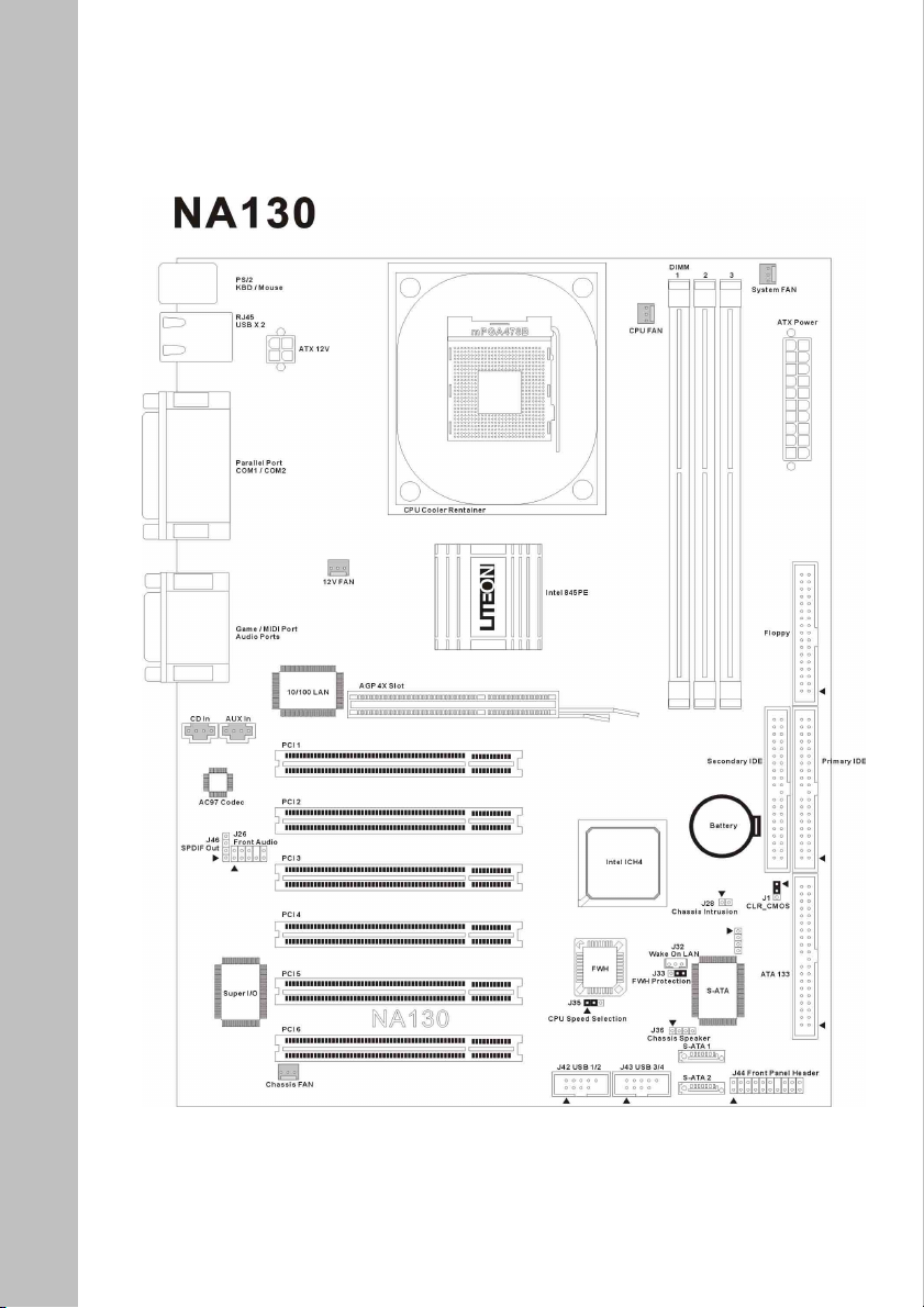
1-2 Layout Diagram
10
Page 11

Chapter 2. Hardware Installation
Before starting installing the mainboard, an ATX12V power supply is required to
meet the power requirement of Intel Pentium
other parts of your system, is subject to damage by static electricity. Be sure that
you’re properly grounded (LITE-ON Technology Corp. recommends that you wear
an anti-static strap or touch a grounded object) and unplug your system before
starting any hardware installation.
This chapter contains the following installation steps:
2-1 Install The Motherboard
2-2 Install the CPU and Heatsink
2-3 Install System Memory
2-4 Install Expansion Cards
2-5 Jumpers, Connectors, Headers and Switches
Before proceeding with the installation, turn the ATX12V
power supply off (fully turn the +5V standby power off), or
disconnect the power cord before you install or unplug any
connectors or add-on cards. Failing to do so may cause the
mainboard components or add-on cards to malfunction or
damaged.
®
4 processor. The mainboard, like
Warning
2-1 Install The Motherboard
Align the mainboard with the computer chassis. Remove any un-aligned studs to
prevent from short-circuiting the mainboard. Install the back I/O shield onto the
chassis first, and then align the mainboard with the I/O shield and the studs. Secure
the mainboard by the correct screws.
11
Page 12
Warning
Failing to remove the un-aligned metal studs may cause shorting
the PCB circuit. Please REMOVE the metal studs or spacers if
they are already fastened on the chassis base and are without
mounting-holes on the motherboard to align with.
2-2 Install the CPU and Heatsink
This motherboard uses a CPU socket called Socket478 to install the 478 pin Intel®
Pentium
fan to prevent CPU from overheating.
Ensure the CPU type is supported by this mainboard.
Please use an Intel approved CPU cooling fan to prevent CPU from
Use proper thermal paste to provide better thermal transfer between
Ensure the CPU fan power cable is firmly plugged into the onboard
®
4 & Celeron® CPU. The PCU should always have a heatsink and cooling
overheating.
CPU and heatsink.
CPU fan connector.
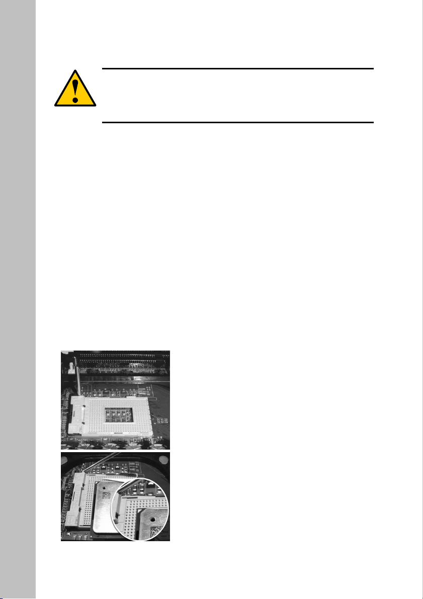
1. Unlock the CPU socket by pulling the lever
up to a 90-degree angle.
2. Position the CPU above the socket such as
that the marked corner (pin 1) matches the
corner near the base of the lever.
12
Page 13
3. Place the CPU into the socket. If the CPU is unable to insert properly, check
its orientation and attempt to re-install.
Warning
DO NOT force the CPU into the socket. Installing the CPU
with force will prompt bending of the pins and create damaged
to the CPU.
4 Close the socket by lowering the lever and locking the lever in place.
5 Place the thermal paste evenly on the top of the CPU IHS (metal plate).
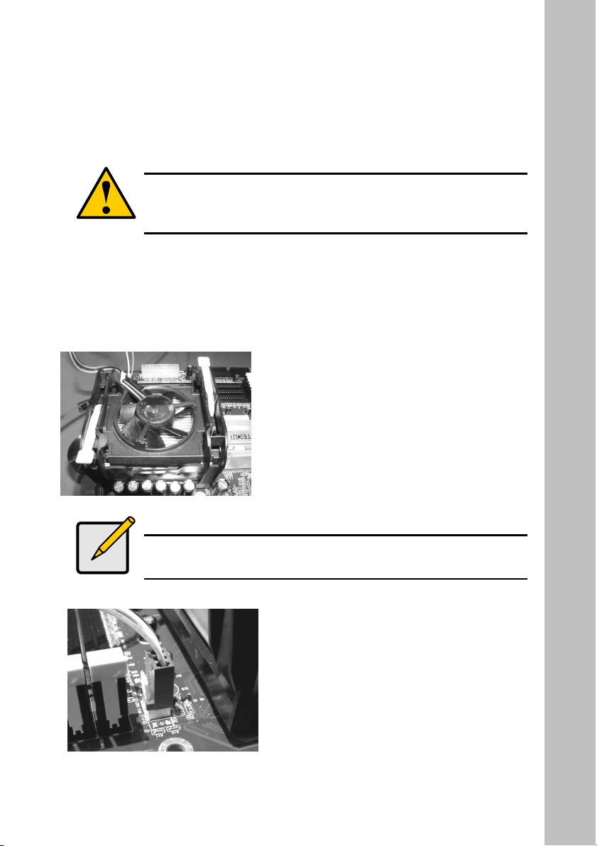
6 Align and place the CPU heatsink on the
top of the CPU IHS.
7 Firmly secure the CPU heatsink onto the
heatsink retainer.
Note
Use only Intel approved CPU coolers. Read the CPU heatsink
user’s manual for more installation procedures.
8. Connect CPU fan power cable into the
CPU fan connector on the motherboard
to complete the CPU installation.
13
Page 14
Warning
Always make sure the CPU cooling fan works properly to
protect the CPU from overheating. Failing to do so will
seriously damage the CPU and system.
2-3 Install System Memory
This motherboard provides three 184-pin DDR DIMM slots for the memory
expansion (DIMM2&DIMM3 are sharing). This mainboard supports a minimum of
64MB up to 2GB of unbuffered DDR333/266 SDRAM (ECC is not supported by
Intel 845 series chipsets). In order to create memory array, certain rules must be
followed. The following set of rules allows for optimum configurations.
Warning
Static electricity can damage the electronic components of the
computer or optional boards. Be sure that you’re properly
grounded and unplug your system before starting any hardware
installation.
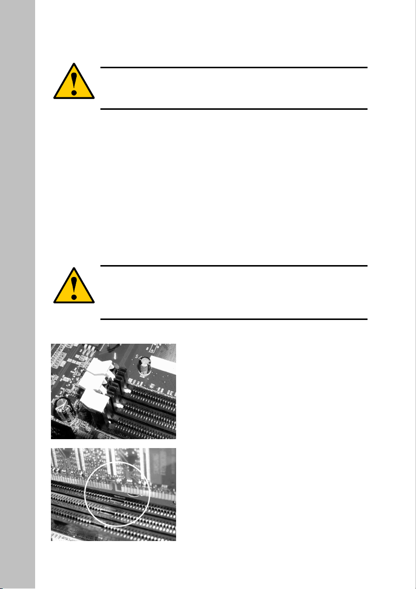
1. Locate the DDR DIMM slot.
2. Push the white retaining clips on each
side of the DDR DIMM slot outward.
3. Matched the notches on the gold-finger
of the memory module to the ridges in
the DIMM socket.
14
Page 15
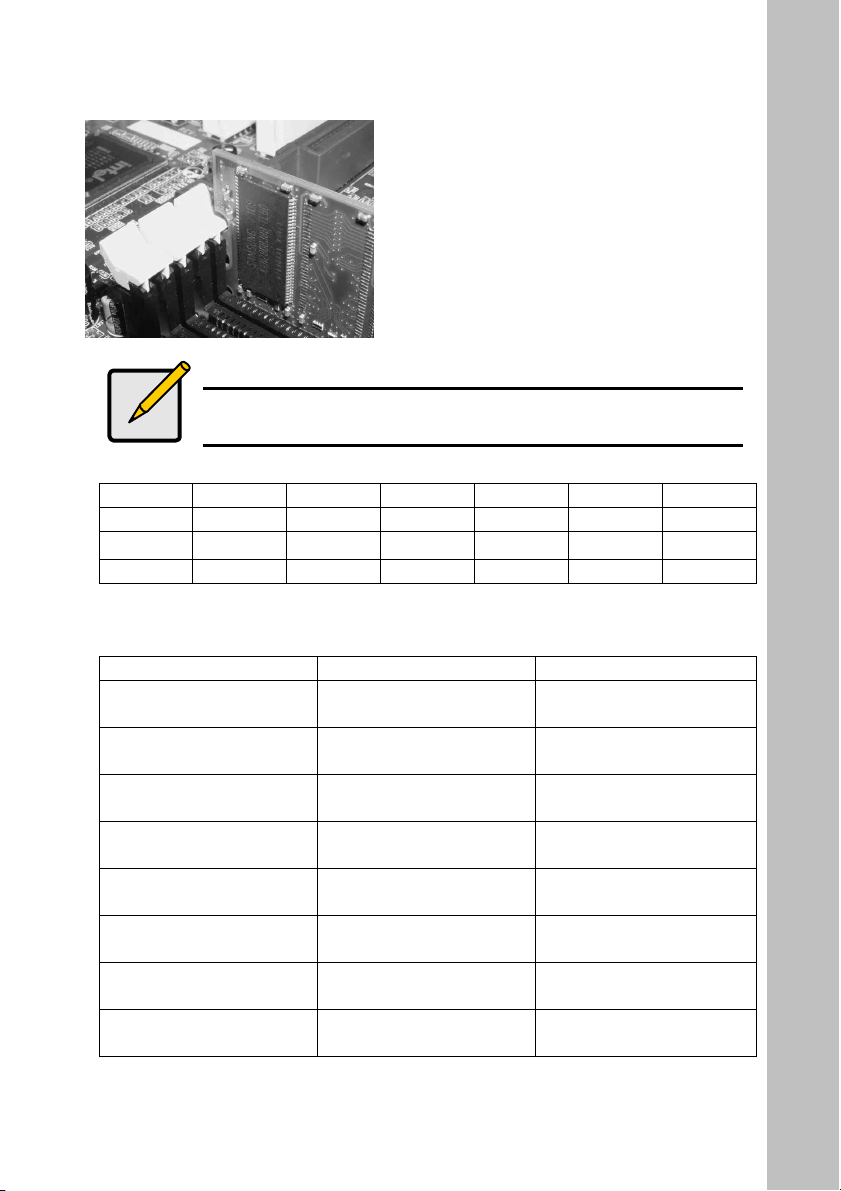
4. Insert the memory module vertically
into place. When properly inserted, the
white retaining clips will move inward
to lock in the module.
Note
DIMM2 and DIMM3 can only occupy by single side DDR
module simultaneity (DIMM2: single side, DIMM3: single side)
Slot Option 1 Option 2 Option 3 Option 4 Option 5 Option 6
DIMM 1 Single Double Single Double Single Double
DIMM 2 Single Single Double Double
DIMM 3 Single Single Double Double
Total Memory Sizes With Unbuferred DDR DIMM
Devices used on DIMM 1 DIMM x 64 2DIMMs x 64
64 Mbit (2M x 8 x 4
banks)
64 Mbit (1M x 16 x 4
banks)
128 Mbit (4M x 8 x 4
banks)
128 Mbit (2M x 16 x 4
banks)
256 Mbit (8M x 8 x 4
banks)
256 Mbit (4M x 16 x 4
banks)
512 Mbit (16M x 8 x 4
banks)
512 Mbit (8M x 16 x 4
banks)
128 MBytes 256 MBytes
64 MBytes 128 MBytes
256 MBytes 512 MBytes
128 MBytes 256 MBytes
512 MBytes 1 GBytes
256 MBytes 512 MBytes
1 GBytes 2 GBytes
512 MBytes 1 GBytes
15
Page 16
2-4 Install Expansion Cards
The mainboard supports one AGP 4X slot (support only 1.5V AGP card) and six
PCI 2.2 32-bit Master PCI bus slots (support 3.3V/5V PCI bus interface).
1. Unpack the expansion cards that you are going to install. Read the expansion
card’s installation guide carefully before install the cards into the mainboard.
2. Disconnect the power or unplug the power cord from the power supply.
3. Remove the computer’s chassis cover and the slot bracket form the chassis.
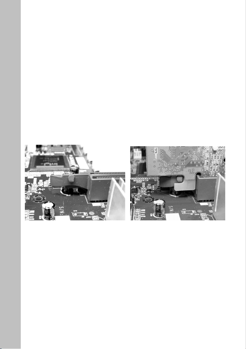
4. Firmly insert the AGP card downward until the AGP card is locked by the
latch on the AGP slot. To remove the AGP card from the AGP slot, please
push the latch sideways to release the AGP card. Ensure the expansion card’s
metal bracket is correctly seated in the intended place.
5. Fasten the expansion card with the correct screw.
6. Connect the necessary cables if required.
16
Page 17

7. Close the computer chassis’s cover and reconnect the power cord to the
power supply.
8. Power up the computer, if necessary, setup BIOS utility of expansion card
form BIOS.
9. Install related driver form the operating system.
2-5 Jumpers, Connectors, Headers and Indicators
Inside the case of any computer there are several cables and jumpers that have to
be connected. These cables and jumpers are usually connected one-by-one to
connectors located on the board. During the installation you have to pay attention
to the orientation of the connectors, headers and the cables. Always locate the
position of the first pin on the connector.
This section will show you all of the connectors, headers and indicators, and how
to connect them. Please read the entire section for necessary information before
attempting to finish all the hardware installation inside the computer. A complete
layout diagram is shown in this manual for all the position of connectors and
headers on the board that you may refer to.
Warning
Before proceeding with the installation. Turn the power supply
off (fully turn the +5V standby power off), or disconnect the
power cord before you install or unplug any connectors or
add-on cards. Failing to do so may cause the mainboard
components or add-on cards to malfunction or damaged.
17
Page 18
1. Jumpers
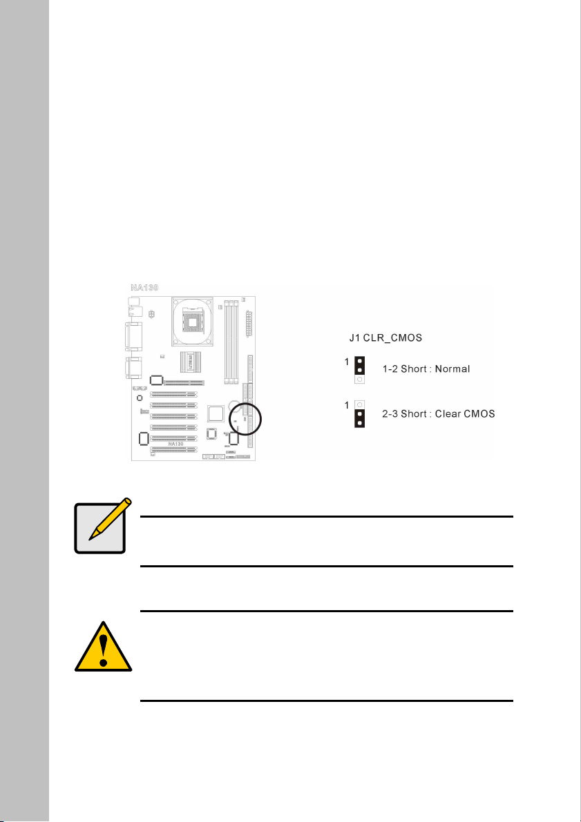
(1) J1 CLR_CMOS ( Erase CMOS data )
This jumper can be used to clear the CMOS data to its default setting
by shorting the pin 2 and pin 3. The default setting is pin 1 and pin 2
shorted – “Normal”. Remember to return the jumper back to pin 1 and
pin 2 position after cleared the CMOS or the system will not boot up.
Pin 1-2 : Normal
Pin 2-3 : Clear CMOS
Note
In the cases of system not booting after changing BIOS setting
or overclocking failed, try to clear the CMOS before re-boot the
system.
Warning
Before clearing the COMS. Turn the power supply off (fully
turn the +5V standby power off), or disconnect the power cord
before you install or unplug any connectors or add-on cards.
Failing to do so may cause the mainboard components or add-on
cards to malfunction or damaged.
18
Page 19
(2) J33 : FWH hardware overwrite protection jumpers
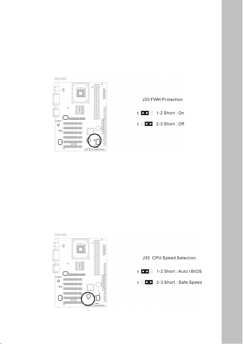
Shorting the pin 1 and pin 2 to lock the FWH to prevent the BIOS from
overwriting and virus attack. The default setting of this jumper is
-“Off”.
Pin 1 and Pin 2 shorted – FWH overwrite protection On.
Pin 2 and Pin 3 shorted – FWH overwrite protection Off.
(3) J35 : CPU speed selection jumper
The default setting of this board is “Auto” CPU detection.
Pin 1 and Pin 2 shorted – Auto / BIOS
Pin 2 and Pin 3 shorted – Safe speed
19
Page 20
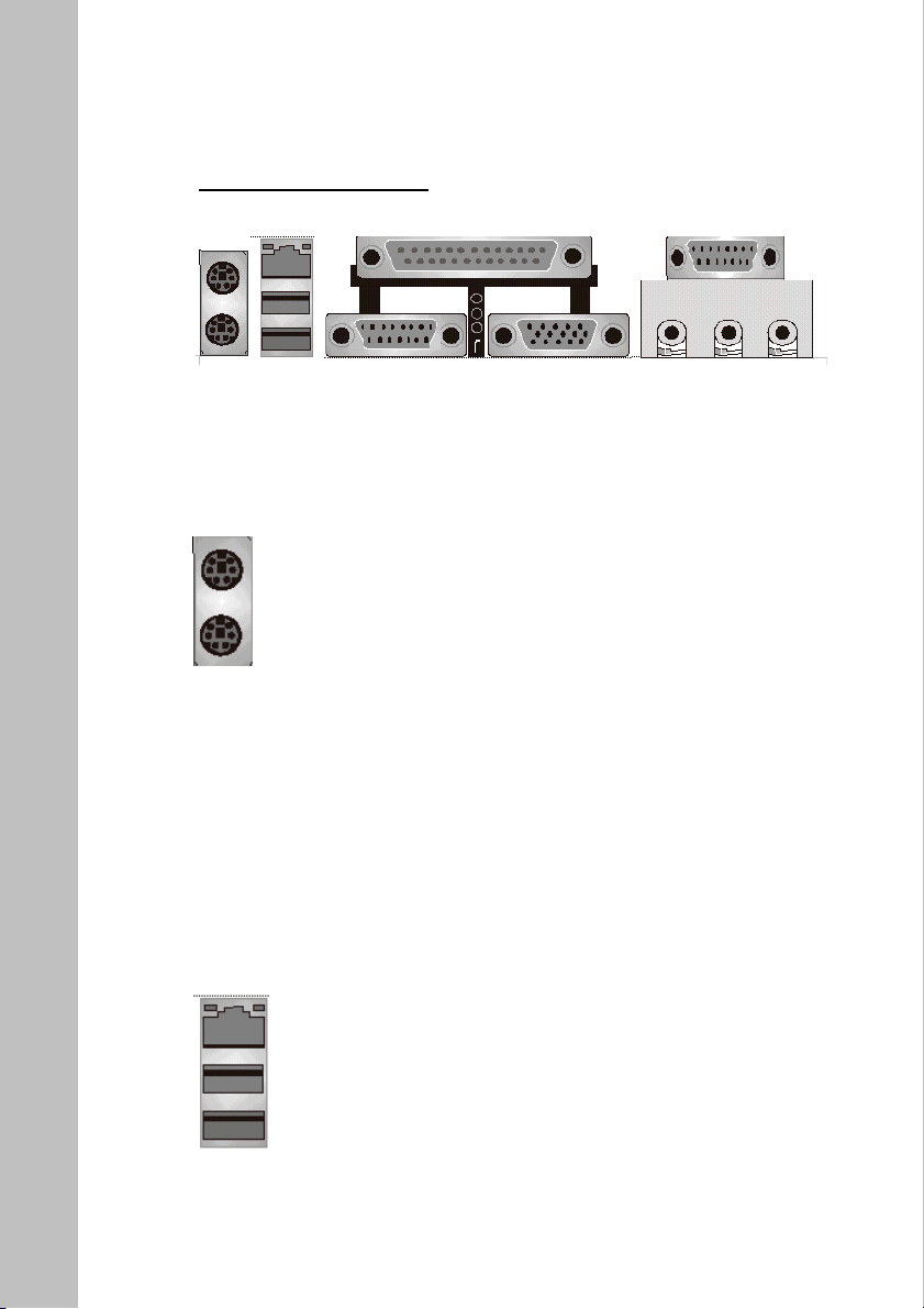
2. Connectors
Back Panel Connectors
(1) PS/2 Keyboard and Mouse
This connector supports industry standard 6 pin PS/2 keyboard and 6
pin PS/2 mouse.
PS/2 Keyboard Connector (Green)
PS/2 Mouse Connector (Purple)
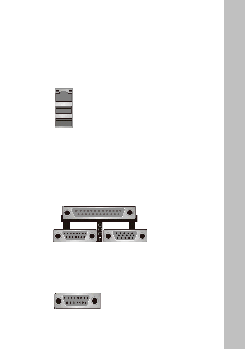
(2) USB2.0 and LAN connector
Before connecting device(s) into the USB connectors, please make
sure if devices meet the standard USB interface. Make sure your
computer Operating System (OS) supports the USB controller. If not,
please acquire the correct driver or patch update. For more information
please contact your OS or device(s) vendors.
USB 2.0
20
Page 21
(3) On Board LAN function (optional)
Before connecting RJ45 networking wire into the LAN connectors,
please make sure you install the correct driver for the onboard 10/100
baseT LAN controller. If not, please acquire the correct driver or
update from the LITE-ON web site or the device vendors.
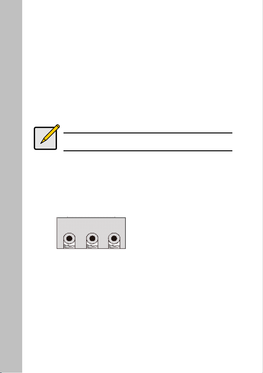
(4) Parallel Port and Serial Ports (COM1/COM2)
This connector set supports one industry standard 25 pin parallel port
and two industry standard 9 pin serial ports.
Parallel port (Magenta)
Serial ports 1 (Green)
Serial ports 2 (Green)
RJ 45
(5) Game/MIDI Port
This 15 pin connector supports joystick and MIDI devices.
Game/MIDI Port (Yellow)
21
Page 22
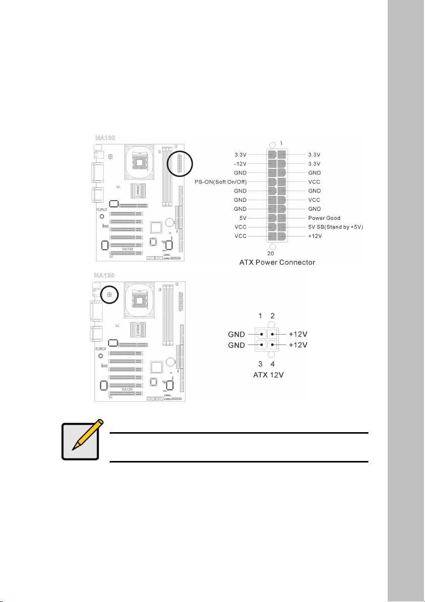
(6) Audio Connectors
This mainboard offers 6 channel audio out put. For the best audio
quality, a 5.1 speaker system is recommended. However, various types
of PC speaker systems are also supported through different wiring.
For 5.1 speaker system please connect the front speaker to the
Line Out jack (green), rear speaker to the Line In jack (blue),
Center/Bass to the MIC In (magenta).
Note
When a 5.1 system is used, the MIC In function is temporary
disabled.
For 4 or 4.1 speaker system please connect the front speaker to
the Line Out jack (green), rear speaker to the Line In jack (blue).
For 2 or 2.1 speaker system please connect the speaker to the
Line Out jack (green).
Line Out Line In MIC In
22
Page 23
(7) ATX Power Connectors and +12V Power Connector
The Pentium
®
4 requires a power supply different from the regular one.
It’s a newly designed ATX12V power with 20A +5VDC capacity, and
720Ma +5VSB at least for supporting Wake-On-LAN function.
Note
Power Supply must meet ATX 2.03 specification with
ATA12V and AUX Power connectors.
23
Page 24
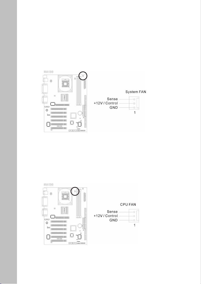
(8) FAN Connectors
FAN1 : System Fan
Pin 1 : GND
Pin 2 : Fan Power
Pin 3 : Fan Speed Sensor
FAN2 : CPU Fan
Pin 1 : GND
Pin 2 : Fan Power
Pin 3 : Fan Speed Sensor
24
Page 25
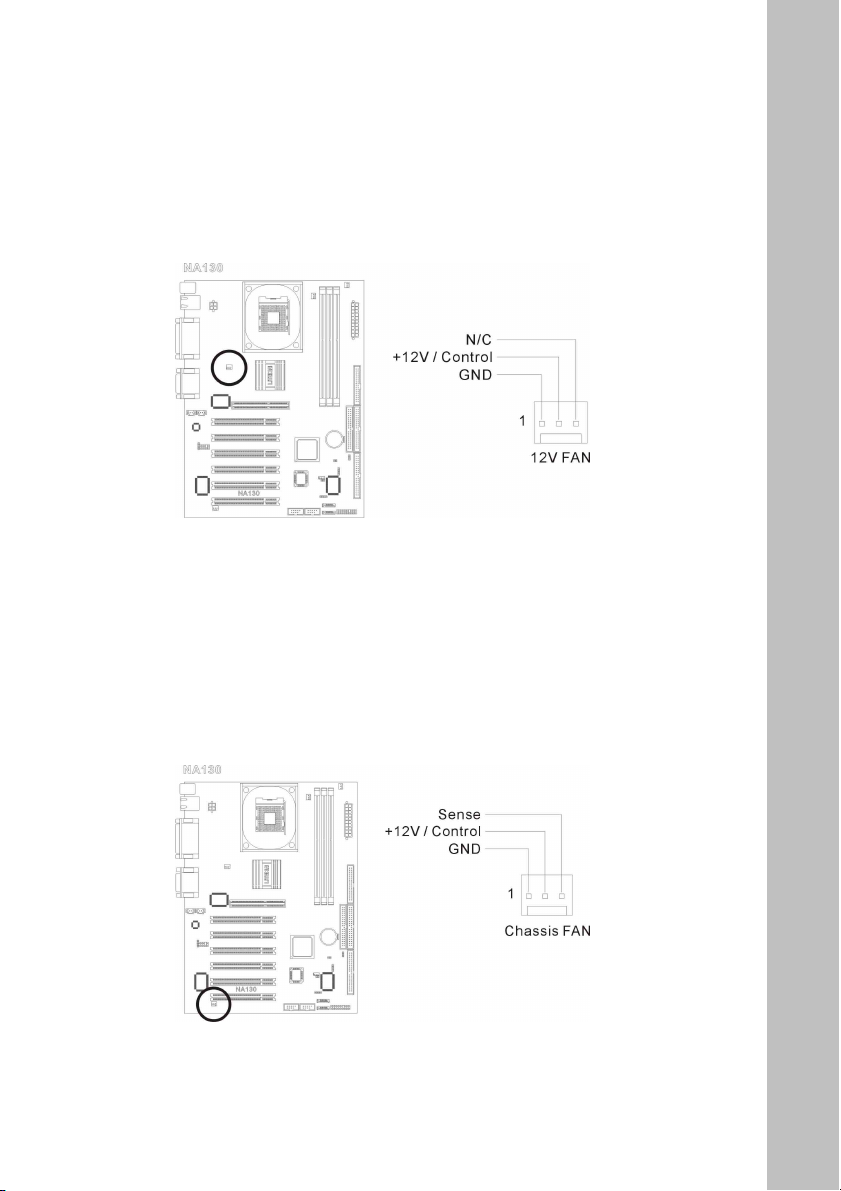
FAN3 : Northbridge Fan (No monitoring function)
Pin 1 : GND
Pin 2 : Fan Power
Pin 3 : N/C
FAN4 : Chassis Fan
Pin 1 : GND
Pin 2 : Fan Power
Pin 3 : Fan Speed Sensor
25
Page 26
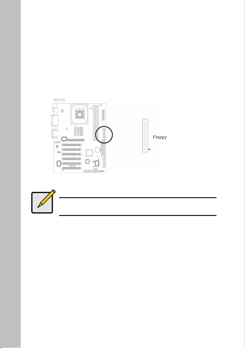
(9) Floppy Connector
There are 34 wires and two connectors on each floppy cable providing
two floppy disk drives connection. Connect the single end at the longer
length of ribbon cable to this FDC1, and the two connectors on the
other end to the floppy disk drives. Generally you need only one floppy
disk drive in yours system.
Note
The red line on he ribbon cable should be aligned with pin I on
this connector.
26
Page 27
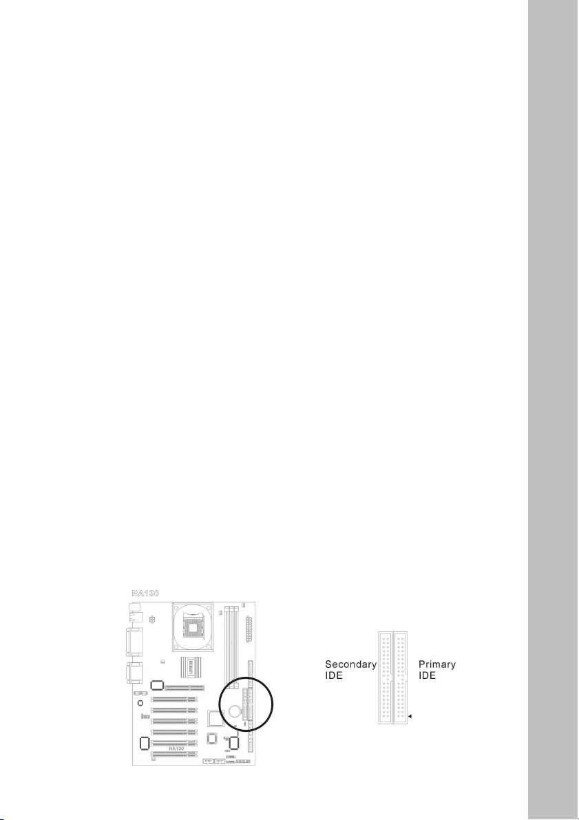
(10) Primary IDE1/ Secondary IDE2 Connectors
This motherboard provides two IDE ports to connect up to four IDE
drives at Ultra ATA/100 mode by Ultra ATA/66 ribbon cables. Each
cable has 40-pin 80-conductor and three connectors, providing two
hard drives connection with motherboard. Connect the single end (Blue
Connector) at the longer length of ribbon cable to the IDE port on
motherboard, and the other two ends (gray and black connector) at the
shorter length of the ribbon cable to the connectors on hard drives.
If you want to connect two hard drives together with one IDE channel,
please configure the drives to Master & Slave accordingly or simply
set the HDD’s jumper to Cable Select. The first drive connected to
IDE1 is usually referred to as ”Primary Master”, and the second drive
as “Primary Slave”. The first drive connected to IDE2 is referred to as
“Secondary Master” and the second drives as “Secondary Slave”.
Please refer to the drives’ documentation for jumper settings.
Always connect the boot disk to the primary IDE connector (Blue) and
the optical drive to the secondary IDE connector (Black). Keep away
from connecting legacy slow speed drive, like CD-ROM, together with
hard drive on the same IDE channel; this will resulting a drop in
system performance.
27
Page 28
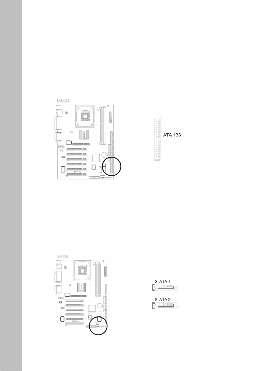
(11) IDE3 (ATA133) Connector
The IDE3 are extra devices controlled by Promise PDC20375 chipset.
This additional feature allows extra 2 Ultra ATA/133 devices
connection. This additional ATA133 connector (Yellow) supports
ONLY ATA devices, such as HDD.
(12) Serial ATA150 Connectors
This mainboard can also supports two Serial ATA150 HDDs through
the onboard Promise PDC20375 Serial ATA controller. Two connectors
are provided to connect one Serial ATA HDD each.
28
Page 29
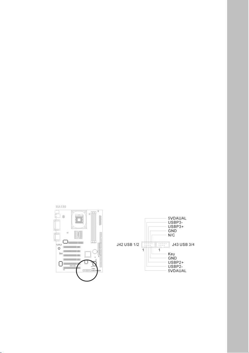
(13) USB2/3: Front USB2.0 Connector
This mainboard provides totally six USB 2.0 ports controlled by Intel
ICH4. Two USB2.0 ports are located at the rear side I/O. The other
four of them are supported through the onboard USB1/2 and USB3/4
headers. Check the polarity of the front USB2.0 connector or the
USB2.0 bracket before installing it to the onboard USB2.0 headers.
Incorrect match polarity will cause damage to the mainboard.
(14) USB3/4: Front USB2.0 Connector
This mainboard provides totally six USB 2.0 ports controlled by Intel
ICH4. Two USB2.0 ports are located at the rear side I/O. The other
four of them are supported through the onboard USB1/2 and USB3/4
headers. Check the polarity of the front USB2.0 connector or the
USB2.0 bracket before installing it to the onboard USB2.0 headers.
Incorrect match polarity will cause damage to the mainboard.
29
Page 30
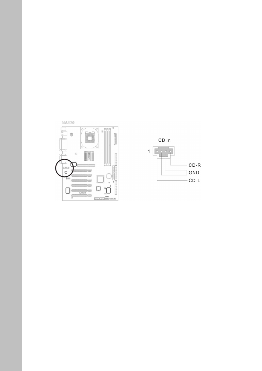
(15) CD In : Internal Audio Connector
These connectors connect to the audio output of internal CD-ROM
drive or add-on card.
Pin 1: CD-In L channel
Pin 2: GND
Pin 3: GND
Pin 4: CD-In R channel
(16) AUX1 : Internal Audio Connector
These connectors connect to the audio output of internal CD-ROM
drive or add-on card.
Pin 1: AUX-In R channel
Pin 2: GND
Pin 3: GND
Pin 4: AUX-In L channel
30
Page 31
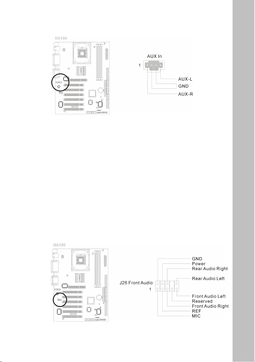
3. Headers and Indicators
(1) J26 : Front panel audio connection header
This header provides the connection to audio connector at front panel.
The default audio out put setting is set at rear. If you want to use the
front panel audio connector, connect the front audio cable to this
header via the extension cable to front panel.
To use the audio connector at rear panel, simply disconnect the
extension cable, and it will back to it’s default setting.
31
Page 32
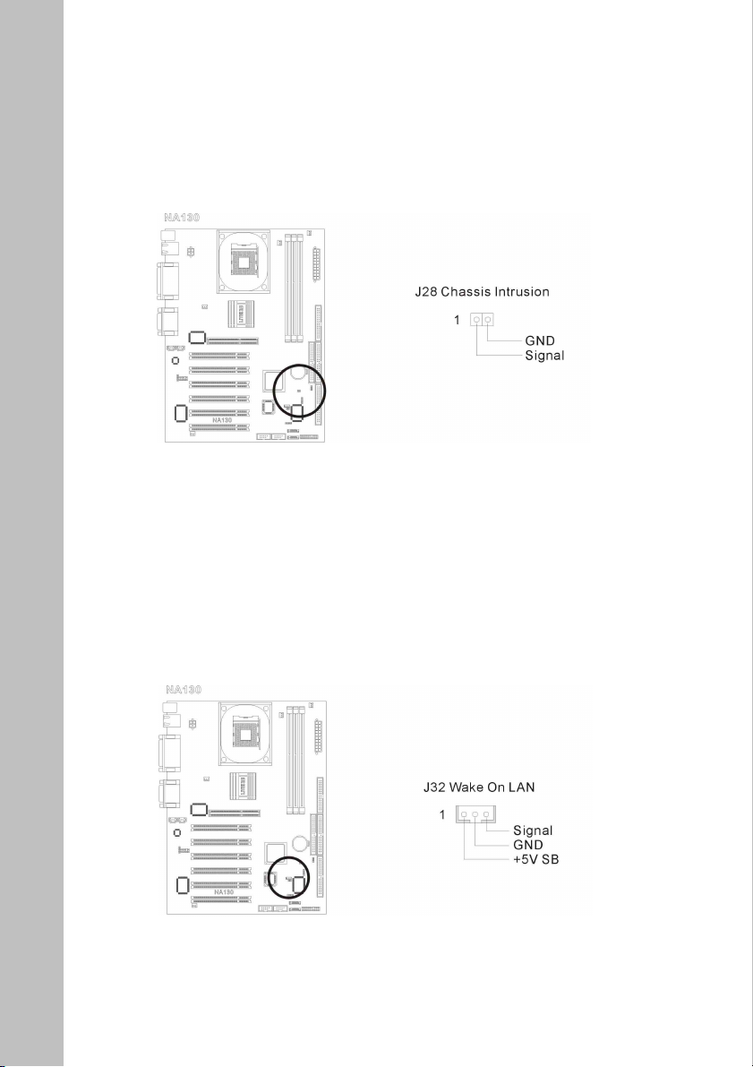
(2) J28 Chassis intrusion header
Pin 2 : GND
Pin 1 : Signal
(3) J32 Wake On LAN header
Pin 1 : SB5V
Pin 2 : GND
Pin 3 : Signal
32
Page 33
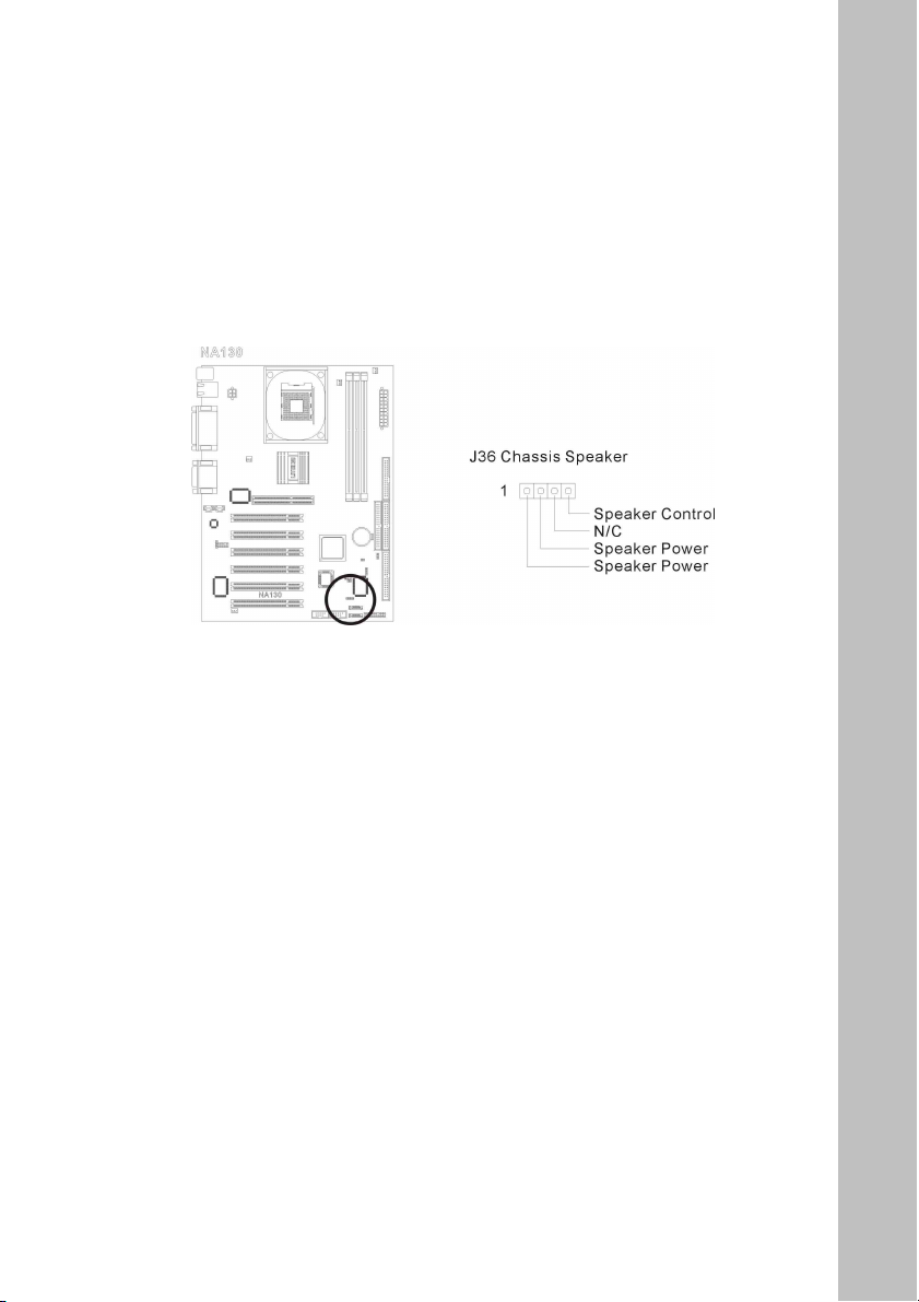
(4) J36 Chassis speaker out header (Mono)
Pin 1 : Speaker power
Pin 2 : Speaker power
Pin 3 : NC
Pin 4 : Speaker control
33
Page 34
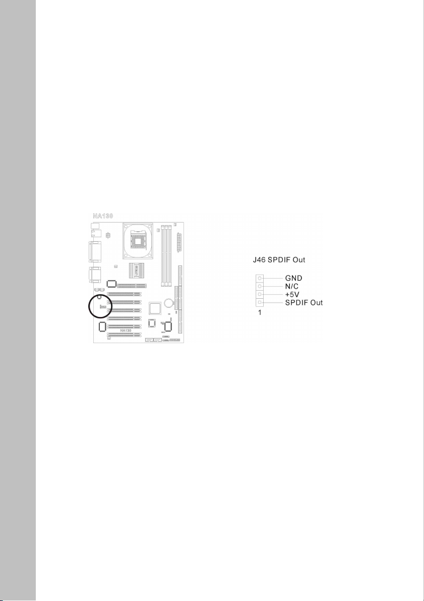
(5) J46 SPDIF header
The SPDIF output is used to provide AC3 (digital audio signal) to the
external Dolby Digital Decoder. This feature only works with an
optional SPDIF output bracket.
Pin 1 : SPDIF Out
Pin 2 : +5V
Pin 3 : NC
Pin 4 : GND
34
Page 35
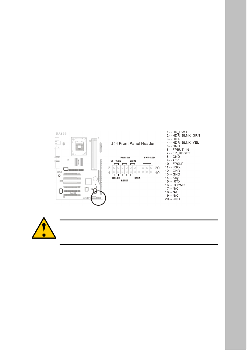
(6) J44 Front Panel header
The header is used for connecting switches and LED indicators on the
chassis front panel.
Watch the power LED pin position and orientation. The mark “+” align
to the pin in the figure below stands for positive polarity for the LED
connection. Please connect the power switch, rest switch, HDD LED
connectors of the chassis to the Front Panel Header according to the
pin assignment shown here. Please pay attention to connect these
headers.
Warning
A wrong orientation will only cause the LED not lighting, but a
wrong connection of the switches could cause system
malfunction or damaged.
35
Page 36

Chapter 3. BIOS Setup
The BIOS is a boot program located in a Flash Memory chip on the mainboard. It
is used to communicate with the hardware before the operating system (OS) takes
the control of the system. Its main function is to manage the setup of the
motherboard and interface card parameters, including simple parameters such as
time, date, hard disk drive, as well as more complex parameters such as hardware
synchronization, device operating mode, and the operating speed of the CPU.
Warning
Don’t change the parameters inside the BIOS unless you
fully understand their meanings and consequences: The
parameters inside the BIOS are used to setup the hardware
synchronization or the device-operating mode. If the parameters
are not correct, they will produce errors, the computer will
crash, and sometimes you will not even be able to boot he
computer after it has crashed. We recommend that you do not
change the parameters inside the BIOS unless you are very
familiar with them. If you are not able to boot your computer
anymore, please refer to Chapter 2 Hardware Installation,
section 2-5 Jumpers -“Erase CMOS data”.
Press <Del> to enter BIOS setup
Immediately press the <Del> key after power up the system. This will let you
access into the BIOS Setup menu. If the post disappears before you response and
the OS (operation system) starts, please restart the system by using the “Start” or
“Reset” button on the chassis.
36
Page 37
How to operate the BIOS menu
In the BIOS Setup menu, you can see several options. You will need the following
function keys to operate the BIOS.
Press<Esc> to exit the BIOS Setup menu.
Press ↑↓← → (up, down, left, right) to choose, in the main menu, the
option you want to confirm or to modify.
Press <F10> to save these parameters into the CMOS and to exit the BIOS
Setup menu.
Press <Page Up>/<Page> Down or <+/-> keys when you want to modify the
BIOS parameters for the active option.
3-1 The Main Menu
After entering the BIOS, the main BIOS menu will appear on the screen. This main
menu allows you to select twelve setup functions and two save/exit choices. Use
the ↑↓← → keys to select the items and press <Enter> to confirm and enter
the sub-menu.
Standard CMOS setup for changing time, date, hard disk type, etc.
AMI BIOS HIFLEX SETUP UTILITY - VERSION 1.54
(C)2001 Aerican Megatrends, Inc. All Rights Reserved
NA130 BIOS Rev: 0.00.09
Standard CMOS Features
Advanced CMOS Features
Advanced Chipset Features
Power Management Setup
PCI / Plug and Play Setup
Peripheral Setup
Hardware Monitor Setup
Auto-Detect Hard Disks
Change User Password
Change Supervisor Password
Auto Configuration with Optimal Settings
Auto Configuration with Fail Safe Settings
Save Settings and Exit
Exit without Saving
ESC: Exit :Sel F2/F3: Color F10:Save & Exit
37
Page 38
Note
The BIOS is being constantly updated to increase stability and
performance, it is therefore the BIOS screens in this manual
may not completely match your BIOS version.
1. Standard CMOS Setup
This setup page includes all the basic configuration parameters of the
BIOS. Including the date, VGA,FDD and the HDDs settings. Use the
keys to select the items and press <Enter> to confirm and
enter the sub-menu.
AMIBIOS SETUP - STANDARD CMOS SETUP
(C)2001 AMERICAN MEGATRENDS, INC. All Rights Reserved
Date (mm/dd/yyyy): Wed Nov 28,2001 Base Memory: 639KB
Time (hh/mm/ss) : 03:26: 0 Extd Memory: 127MB
Floppy Drive A: 1.44 MB 3½
Floppy Drive B: Not Installed
Type Size Cyln Head Wpcom Sec Mode Mode Mode Mode
Pri Master: Not Installed
Pri Slave : Not Installed
Sec Master: User 40027Mb 19161 16 0.. 255 On On 4 On
Sec Slave : CD-ROM 3 On
Boot Sector Virus Protection Disabled
Month: Jan-Dec
Day: 01-31 PgUp/PgDn: Modify
Year: 1980-2099 F1: Help F2/F3:Color
LBA BLK PIO 32Bit
ESC: Exit : Sel
38
Page 39

Date (mm: dd: yy):
You can set the date in this item: month (mm), date (dd) and year (yy).
Time (hh: mm: ss):
You can set the time in this item: hour (hh), minute (mm) and second
(ss).
Drive A & Drive B:
If you have installed the floppy disk drive here, then you can select the
type of floppy drive it can support. Available option: (None) (360K,
5.25 inch) (1.2M, 5.25 inch )
(720K, 3.5 inch) (1.44M, 3.5 inch) (2.88M, 3.5 inch)
IDE Primary Master / Slave and IDE Secondary Master / Slave:
This section identifies the types of the FDD and HDDs that are
installed in the system. You may manually define the parameters of the
FDD and the HDDs used on your system by entering the information
correctly from the keyboard. Please refer to the HDDs specification
before entering the parameters. It is recommended to use “Auto Detect
Hard Disk” form the BIOS main menu and let the BIOS detect your
HDDs to speed up the booting time.
LBA Mode:
Blk Mode:
PIO Mode:
32Bit Mode:
Virus Protection:
Available option: On and Off.
Available option: On / Off.
Available option: Auto, 0, 1, 2, 3, 4, 5.
Available option: On / Off.
Enabled / Disabled ( the factory default is
Disabled).
39
Page 40

Size: The HDD size based on Mega Byte.
Cylinder: The total number of cylinders of the hard disk.
Head: The total number of the read / write heads of
the hard disk.
Wpcom: Write precom. Ranging from 0 to the
maximum of 65536.
Sectors: The total number of the sectors defined on the
hard disk.
Note
A new IDE HDD must be first formatted, otherwise it can not
read/write. The basic step in using a HDD is to make a HDD
low-level format, then run FDISK, and then FORMAT the drive.
Most current HDDs have already been subjected to low-level
format at the factory, so you can probably skip this operation.
Remember though, the primary IDE HDD must have its
partition set to active within the FDISK procedure. If you are
using an old HDD that is already formatted, auto detection can
detect the correct parameters. You may need to do a low-level
format or set the parameters manually, and then check if the
HDD is working.
40
Page 41
2. Advanced CMOS Setup
This setup page includes user definable BIOS configuration
parameters.
AMIBIOS SETUP - ADVANCED CMOS SETUP
(C)2001 American Megatrends, INC. All Rights Reserved
Quick Boot Enabled Available Options:
1st Boot Device CD/DVD
2nd Boot Device Floppy
3rd Boot Device IDE-0
Try Other Boot Devices Yes
Initial Display Mode BIOS
S.M.A.R.T. for Hard Disks Disabled
BootUp Num-Lock
Floppy Drive Swap Disabled
Floppy Device Seek Disabled
PS/2 Mouse Support Enabled
System Keyboard Present
Password Check Setup
C000 , 32K Shadow Cached
C800 , 16K Shadwo Disabled
CC00 , 16K Shadow
D000 , 16K Shadow Disabled
D400 , 16K Shadow Disabled
D800 , 16K Shadow Disabled PgUp/PgDn: Modify
DC00 , 16K Shadow Disabled F1: Help F2/F3:Color
On
Disabled
Disabled
Enabled
ESC: Exit : Sel
Quick Boot
This feature enables a faster booting time. The default setting is
Enabled.
Available option: Enabled / Disabled.
41
Page 42

First Boot Device:
When the computer boots up, the BIOS attempts to load the operating
system from the devices in sequence selected in these items: floppy
disk drive A, LS/ZIP devices, hard drive C, SCSI hard disk drive or
CD-ROM. There are various options for the boot sequence that you can
choose (The default setting is CD/DVD).
Second Boot Device:
The description is the same as the First Boot Device. The default
setting is Floppy.
Third Boot Device:
The description is same as the First Boot Device. The default setting is
IDE0.
Other Boot Device:
This setting allows the BIOS to boot from other devices that are
st
installed in the system, if the system failed to boot from 1
/ 2
nd
/ 3rd
boot devices. The default setting is Yes.
Available option: Yes / No.
S.M.A.R.T: for Hard Disks:
This feature allows you to activate the S.M.A.R.T. (Self-Monitoring
Analysis & Reporting Technology) function for the hard disk.
S.M.A.R.T. is a utility that constantly monitoring the HDD and predict
the hard disk failure. This helps you to backup the valuable data in the
hard disk to a safe area before the hard disk failed. The default setting
is Disabled. Available option: Enabled / Disabled.
42
Page 43

Boot Up NumLock:
On: At boot up, the Numeric Keypad is in numeric mode. (Default
Settings)
Off: At boot up, the Numeric Keypad is in cursor control mode.
Floppy Drive Swap:
When this feature is enabled, you don’t need to open the computer case
to swap the position of floppy disk drive connectors. Drive A can be
set as drive B and drive B can be set as drive A. The default setting is
Disabled. Available option: Enabled / Disabled.
Floppy Drive Seek:
When the computer boots up, the BIOS detects if the system has an
FDD or not. When this item is enabled, if the BIOS detects no floppy
drive, it will display a floppy disk drive error message. If this item is
disabled, the BIOS will skip this test.
The default setting is Disabled. Available option: Enabled / Disabled.
PS/2 Mouse Support:
This feature allows you to chose enable / disable PS/2 mouse support.
The default setting is Enabled.
Warning
If you are not familiar with each of the options listed in this
BIOS section, it is recommend to use the default setting.
43
Page 44
3. Advanced Chipset Setup
This setup page includes a chipset configuration parameters. This menu
is used to modify the parameters of the chipset on the motherboard.
Since these parameters are closely related to hardware, if the altered
parameters are not correct, the mainboard will become unstable or not
booting up.
(C)2001 American Megatrends, INC. All Rights Reserved
******** DRAM Timing ******** Available Options:
SDRAM Frequence Auto
Configure SDRAM Timing by SPD Enabled
SDRAM CAS# Latency 2.5 Clocks
SDRAM RAS# Precharge 3 Clocks
SDRAM RAS# to CAS# Delay 3 Clocks
SDRAM Precharge Delay
SDRAM Burst Length
APIC Interrupt Mode Enabled
MPS Revision 1.1
AGP Aperture Size 64MB
USB Controller 6 USB Ports
USB 1.1 Device Legacy Support Disabled
PgUp/PgDn: Modify
F1: Help F2/F3:Color
AMIBIOS SETUP – ADVANCED CHIPSET SETUP
200Mhz
266Mhz
7 Clocks
4
333Mhz
Auto
ESC: Exit : Sel
SDRAM Frequency:
This section allows you to define the operating frequency of the
SDRAM used on the system. There are four options to choice from:
200Mhz, set the DDR SDRAM to operate at 200Mhz.
266Mhz, set the DDR SDRAM to operate at 266Mhz.
333Mhz, set the DDR SDRAM to operate at 333Mhz.
Auto, set the DDR SDRAM operating speed by SPD.
44
Page 45

Configure SDRAM by SPD:
This feature allows BIOS to detect the DDR SDRAM information
from the SDRAM’s SPD.
SDRAM CAS Latency Time:
This item controls the latency between the DRAM read command and
the time that the data becomes actually available. The options are: (1.5
Clocks) (2 Clocks) (2.5 Clocks)
SDRAM RAS# Precharge:
This item controls the idle clocks after issuing a pre-charge command
to the DRAM. When an insufficient pre-charge time is given before the
SDRAM to refresh, the refresh process may failed. Thus the data
stored in SDRAM will be lost.
Available options: 2 Clocks / 3 Clocks.
SDRAM RAS to CAS# Delay:
This item controls the latency between the DRAM active command
and read/write command. Shorter the cycle better the performance,
while longer cycle offers more stable system performance. Available
options: 2 Clocks / 3 Clocks
SDRAM Precharge Delay:
This section specifies the idle cycles before pre-charging an idle bank.
Available options: 7 Clocks / 6 Clocks / 5 Clocks.
45
Page 46

SDRAM Burst Length:
This section specifies the size of the SDRAM burst length. SDRAM
uses a technique described as “Bursting” to predict the address of the
next memory location after the first address is accessed. Set the longer
burst length to speed up the DRAM performance.
Available options: 4 / 8.
ACPI Interrupt Mode:
This feature allows use to enable or disable the power saving “Green”
function of the system. Available options: Enabled / Disabled. The
default setting is Enabled.
MPS Revision:
This section specifies the version of the MPS (Multi-Processor
Specification) to be used for the operation system.
AGP Aperture Size:
The options are: 4, 8, 16, 32, 64, 128, and 256MB. The default setting
is 64MB. This option specifies the amount of system memory that can
be used by the AGP device. The aperture is a portion of the PCI
memory address range dedicated for graphics memory address space.
Host cycles that ht the aperture range are forwarded to the AGP
without any translation. See www.agpforum.org
information.
46
for more AGP
Page 47

USB Controller:
This section allows you to have the control over the status of the
onboard USB ports. This mainboard provides two Universal Serial Bus
(USB) ports on the back I/O, four additional ports via the USB bracket.
If you don’t want to use USB devices, set it to Disabled, then the item
USB Keyboard Support & USB Mouse Support will also be disabled.
Available option: Disabled / 2 USB Ports / 4 USB Ports / 6 USB Ports.
The default setting is 6 USB Ports.
USB 1.1 Device Legacy Support:
This mainboard supports both USB2.0 & USB1.1 specifications. Set
this section to “All devices” if a USB1.1 device is going to be used on
an operating system do not support or have USB driver installed, such
as DOS. A mix use of USB2.0 and USB1.1 will drag the performance.
Available options: Disabled / No Mice / All Devices.
The default setting is Disabled.
If you are not familiar with each of the options listed in this
BIOS section, it is recommend to use the default setting.
4. Power Management Setup
This setup page indicates the ACPI power management status, and can
be setup to reduce power consumption. This mainboard supports S1,
S3 (STR), S4 and S5 ACPI power saving mode. Before setting up the
ACPI (Advanced Configuration and Power Interface) functions to the
system. There are few things that you should beware of:
Warning
47
Page 48
The operating system must support ACPI.
All devices and add-on cards in your system must fully
support ACPI, both hardware and software (drivers).
Please contact your device or add-on card manufacturer for more
information. Please go to the address below for more detailed ACPI
information: http://www.acpi.info/
(C)2001 American Megatrends, Inc. All Rights Reserved
ACPI Standby State S1/POS Available Options:
USB Device Wakeup From S3 Disabled
Video Power Down Mode Suspend
Hard Disk Power Down Mode Suspend
Suspend Time Out (Minute) Disabled
Throttle Slow Clock Ratio 50.00%
Power Button Function
Restore on AC/Power Loss
Resume On LAN Disabled
Resume On PME# Enabled
Resume On RTC Alarm Disabled
RTC Alarm Date 15
RTC Alarm Hour 12
RTC Alarm Minute 30
RTC Alarm Second
PgUp/PgDn: Modify
F1: Help F2/F3:Color
AMIBIOS SETUP – POWER MANAGEMENT SETUP
S1/POS
S3/STR
Auto
ON/Off
Last State
30
ESC: Exit : Sel
ACPI Standby State:
Available options: (S1 / POS) (S3 / STR) (Auto).
The default setting is S1.
48
Page 49

USB Device Wakeup From S3:
This section specifies weather the system will be wake up from power
saving mode by a specified USB peripheral. The S3 STR function
needs to be turned on before this feature is enabled.
Available options: Enabled / Disabled.
The default setting is Disabled.
Video Power Down Mode:
Available options: Enabled / Stand By / Suspend.
The default setting is Suspend.
Hard Disk Power Down Mode:
Available options: Enabled / Stand By / Suspend.
The default setting is Suspend.
Suspend Time Out:
Available options: Disabled / 1, 2, 4, 8, 10, 20, 30, 40, 50, 60.
The default setting is Disabled.
Throttle Slow Clock Ratio:
Available options: 87.5% / 75.0% / 62.5% / 50% / 37.5% / 25% /
12.5%.
The default setting is 50%.
Power Button Function:
Available options: On / Off / Suspend.
The default setting is On /Off.
49
Page 50

Restore on AC/Power Loss:
Available options: Power Off / Power On / Last State.
The default setting is Last State.
Resume On LAN:
This section specifies weather the system will be wake up from power
saving mode by a specified peripheral.
Available options: Enabled / Disabled.
The default setting is Disabled.
Resume On PME#:
This section specifies weather the system will be wake up from power
saving mode by a specified peripheral.
Available options: Enabled / Disabled.
The default setting is Enabled.
Resume On RTC Alarm:
Use this feature to set up the regular booting schedule from the S5 (soft
off) state.
Available options: Enabled / Disabled.
The default setting is Disabled.
The scheduling table will enabled after “Resume On RTC Alarm” is set
to Enabled.
Key in the figure into each section of Alarm Date / Alarm Hour / Alarm
Minute / Alarm Second, accordingly to complete the setup.
50
Page 51
5. PCI / Plug and Play Setup
This setup page describes the configuration of the PCI bus system. This
section covers some technical terms and it is not recommended to alter
by amateur users.
(C)2001 American Megatrends, Inc. All Rights Reseved
Clear NVRAM No Available Options:
PCI Latency Timer (PCI Clocks) 32 No
Init. Graphics Adapter Priority AGP/Int-VGA Yes
PCI IDE BusMaster Diabled
AMI BIOS SETUP – PCI/PLUG AND PLAY SETUP
ESC: Exit : Sel
PgUp/PgDn: Modify
F1: Help F2/F3: Color
Clear NVRAM:
The NVRAM (Non Volatile Random Access Memory) is where the
BIOS stores the information for both PnP and non-PnP devices. When
the item is set to “Yes”, the system will reset the NVRAM right away
after the system is booted up, and then set the setting back to “No”
automatically.
Available options: Yes / No.
The default setting is No.
PCI Latency Timer (PCI Clocks):
This section specifies how long each PCI device can occupies the bus
before other PCI devices take over. Set the figure to higher value for
better PCI performance.
Available options: 32 / 64 /96 / 128 / 160 / 192 / 224 / 248.
The default setting is 32.
51
Page 52

Init Graphics Adapter Priority:
When you install an additional display card, you can choose either a
PCI display card or an AGP display card to activate the display boot-up
screen.
Available options: (AGP / PCI) (PCI / AGP)
The default setting is AGP / PCI.
PCI IDE Bus Master:
This feature allows an external PCI IDE controller slotted on PCI local
bus to have bus mastering capability.
Available options: Enable / Disable.
The default setting is Disabled.
52
Page 53
6. Integrated Peripheral Setup
This setup page describes the configuration of the onboard I/O devices,
I/O port address and other hardware setting.
(C)2001 American Megatrends, Inc. All Rights Reserved
OnBoard IDE Both Available Options:
OnBoard LAN Enabled Disabled
OnBorad Lan Chip Boot Rom Disabled Primary
OnBoard AC’97 Enabled
OnBoard FDC Auto
OnBoard Serial PortA Auto
OnBoard Serial PortB Auto
Serial PortB Mode Normal
IR Duplex Mode Half Duplex
IR Pin Select IRRX/IRTX
OnBoard Parallel Port Auto
Parallel Port Mode ECP
EPP Version N/A
Parallel Port IRQ Auto
Parallel Port DMA Channel Auto
OnBoard Midi Port
Midi IRQ Select 5
OnBoard Game Port 200
Keyboard PowerOn Function Disabled
Specific Key for PowerOn N/A
Mouse Power On Function Disabled
AMI BIOS SETUP – PERIPHERAL SETUP
Both
330
ESC: Exit : Sel
PgUp/PgDn: Modify
F1: Help F2/F3: Color
Onboard IDE:
When this function enabled, it allows you to use the onboard Primary
and Secondary IDE controller. If an additional IDE controller card is
used to connect to the HDDs, set it to “Disabled”.
Available options: (Disabled) (Primary) (Secondary) (Both).
The default setting is Both.
53
Page 54

Onboard LAN: (optional)
When this function enabled, it allows you to use the onboard
10/100baseT LAN controller. Available options: Enabled / Disabled.
The default setting is Enabled.
Onboard LAN Chip Boot Rom:
When this function enabled, it allows you to use remote boot function
via the onboard 10/100baseT LAN controller.
Available options: Enabled / Disabled.
The default setting is Disabled.
Onboard AC’97 Audio:
When this function enabled, it allows you to use the onboard AC97
audio codec to deliver the 6 channel audio out put.
Available options: Enabled / Disabled.
The default setting is Enabled.
Onboard FDC:
This section is used to enabling or disabling the onboard floppy
controller.
Available options: Auto / Enabled / Disabled.
The default setting is Auto.
54
Page 55

Onboard Serial Port A / B:
This section specifies the base I/O port address of the onboard Serial
Port A / B. Select “Auto” to automatically determine the appropriate
I/O address.
Available options: (Auto) (3F8 / COM1) (2F8 / COM2) (3E8 / COM3)
(2E8 / COM4) (Disabled).
The default setting is Auto.
Serial Port B Mode:
This section specifies the operation mode for Serial Port B.
Available options: (Normal) (1.6uS) (3/16 Baud) (ASKIR).
The default setting is Normal.
IR Pin Select:
Set to IRRX/IRTX when an internal IR module is used to connect to
the IR header. Select SINB/SOUTB when an IR adapter is connected
to COM B.
Available options: (IRRX / IRTX) ( SINB / SOUTB)
The default setting is IRRX/IRTX.
Onboard Parallel Port:
This section specifies the base I/O port address of the Onboard Parallel
Port. Select “Auto” to automatically determine the appropriate I/O
address.
Available options: (Auto) (378) (278) (3BC) (Disabled).
The default setting is Auto.
55
Page 56

Onboard MIDI / Game Port:
This section specifies the base I/O port address for the onboard MIDI
/Game Port.
Keyboard PowerOn Function:
This function allows you to set the method of powering up the system.
Disabled: Disable the function
Password: Enter 1~5 characters to set the password for Keyboard
Power On
Keyboard 98: Select this to use standard Keyboard 98 (with
Power Key) to power up the system.
The default setting is Disabled.
Mouse PowerOn Function:
This function allows you to use mouse to power up the system.
Available options are: Disable / Left –Button / Right-Button.
The default setting is Disabled.
56
Page 57

7. Hardware Monitor Setup
This setup page describes the PC health status, including temperature
(CPU, system), fan speed (CPU, system, chassis) and the voltage (CPU,
AGP, system power).
(C)2001 American Megatrends, Inc. All Rights Reserved
CPU Ratio Selection Lcoked
CPU Host Clock (CPU/PCI,Mhz) Auto
CLK Spread Spectrum Disabled
Chassis Intrusion Disabled
Shutdown Temperature Disabled
CPU Voltage Control 1.500V
Chipset Voltage Control 1.5V
Memory Voltage Control 2.5V
-== System Hardware Monitor ==-
Current CPU Temperature
Current System Temperature
Current CPU Fan Speed 3950 RPM
Current Chassis Fan Speed 2650 RPM
Current Power Fan Speed 0 RPM
Vcore 1.500 V
+1.25V 1.121 V
+1.5V 1.532 V
+2.5V 2.417 V
+3.3V 3.264 V PgUp/PgDn: Modify
+5V 5.113 V F1: Help F2/F3: Color
+12V 11.437 V
+5V SB 4.945 V
Battery 2.816 V
AMI BIOS SETUP –HARDWARE MONITOR SETUP
35℃/77℉
30℃/86℉
ESC: Exit : Sel
57
Page 58

CPU Ratio Selection:
This function allows user to adjust the CPU multiplier. The multiplier
is used to determine the internal clock speed of the processor relative
to the external clock speed. The number of clock ratio is depends on
the CPU installed.
Note
This function only works when an unlocked multiplier CPU is
used. A production Intel Pentium 4 processor is shipped with
multiplier locked.
CPU Host Clock (CPU/PCI,Mhz):
This function allows user to Auto or Manually adjust the CPU host
clock (FSB) from 100Mhz to 200Mhz by 1 Mhz increment. Available
options are: Auto / Semi-Auto.
The default setting is Auto.
Depending on the CPU used, a two stage FSB selection will be
automatically set. Use + / - key to increase / decrease the FSB speed by
1 Mhz increment.
Pentium 4 with 100Mhz FSB – 100~133Mhz
Pentium 4 with 133Mhz FSB – 133~200Mhz
A smart safety feature is employed in this mainboard to set the system
back to the CPU’s default setting after the OverClocking failed.
CPU Frequency Set Up Procedure
CPU core speed = Host Clock x Core/Bus ratio
For example: 2.53GHz CPU is derived from:
CPU Clock 133MHz X Core/Bus ratio 19
= 133MHz X 19 = 2.53GHz
Note
58
Page 59

Warning
This motherboard is designed with overclocking features.
However, before attempting to overclock the CPU, please make
sure your CPU and other components such as VGA card, PCI
cards and HDDs are able to tolerate such out of spec setting.
LITE-ON Technology assumes no liability for the damages
or risks caused by overclocking operation or operations
beyond product specifications.
CLK Spread Spectrum:
By enabling the Spread Spectrum function, it greatly reduces the EMI
(Electromagnetic Interference) generated by the CLK (clock generator).
Leave this setting at “Disabled” for optimal system performance, if you
have no EMI concern.
When you are attempting to overclock your system, disabling
the Spread Spectrum to increases the stability.
Chassis Intrusion:
This feature allows you to enabling or disabling the function of issuing
an alarm, when the chassis had been opened. To clear the warning
message, set this selection to “Reset”. It will return to “Enabled” later.
Available options: Enabled / Reset / Disabled.
The default setting is Disabled.
Warning
59
Page 60

Shutdowm Temperature:
This feature allows you to set the CPU shutdowm temperature
manually to offer extra thermal protection for your CPU.
Available options: (Disabled) (60℃ /140℉) (70℃ / 150℉)
(80℃ / 160℉) (90℃ / 170℉).
The default setting is Disabled.
CPU Voltage Control:
This setting is used to enable or disable the ability to manually adjust
the CPU Vcore for overclocking purpose.
Available options: 1.5V / 1.55V / 1.6V /1.65V /1.7V / 1.75V / 1.8V /
1.85V.
The default setting is Default to the CPU installed.
The Intel Socket 478 Pentium 4 shipped at different generations
& stepping. The Vcore requirement of the P4 is vary from 1.5V
~ 1.85V depending from it’s generations & stepping. This
mainboard will auto detect the default value of the CPU. You
may later, adjust the Vcore value manually.
Over voltage might cause permanent damage to the CPU,
DRAM, AGP card & the mainboard. LITE-ON Technology
assumes no liability for the damages or risks caused by
overclocking operation or operations beyond product
specifications.
Note
Warning
60
Page 61
Chipset / AGP Voltage Control:
This setting is used to enable or disable the ability to manually adjust
the voltage of chipset (MCH) and AGP for overclocking purpose.
Available options: 1.5V / 1.6V / 1.7V / 1.8V.
The default setting is + / - 1.5V.
Warning
Over voltage might cause permanent damage to the CPU,
DRAM, AGP card & the mainboard. LITE-ON Technology
assumes no liability for the damages or risks caused by
overclocking operation or operations beyond product
specifications.
Memory Voltage Control:
This setting is used to enable or disable the ability to manually adjust
the voltage for system memory for overclocking purpose.
Available options: 2.5V / 2.6V / 2.7V /.2.8V
The default setting is + /- 2.5V.
Over voltage might cause permanent damage to the CPU,
DRAM, AGP card & the mainboard. LITE-ON Technology
assumes no liability for the damages or risks caused by
overclocking operation or operations beyond product
specifications.
Warning
61
Page 62

8. Auto Detect Hard Disk
This setup page auto detects and describes the hard disk status. Press
the <Enter> key for the BIOS to auto detect all detailed parameters of
the hard disk drives (HDD). If auto detection is successful, the correct
values will be shown in this menu.
A new IDE HDD must be first formatted, before it can be
detected. Most current HDDs have already been subjected to
low-level format at the factory, so you can probably skip this
operation.
9. Change User Password
This setup page allows the change, set or disable the user password.
10. Change Supervisor Password
Note
This setup page allows the change, set or disable the supervisor
password.
11. Auto Configuration with Optimal Setting
This setup page allows user to load the best performance configuration
set by the manufacture.
12. Auto Configuration with Fail Safe Setting
This setup page allows user to load the most stable system
configuration.
62
Page 63

13. Save Setting and Exit
Save the adjusted CMOS values to the CMOS and exit this setup
menu.
14. Exits without Saving
Discard the adjusted CMOS value, and exit this setup menu.
63
Page 64

Chapter 4. Driver & Utility Installation
The LITE-ON CD installer features an auto installation program that will
automatically detect the model of the mainboard and automatically install the
necessary drivers to it. All necessary drivers will be installed by just a “click” of
the mouse. This feature greatly reduced the chance on installing the wrong drivers
to the mainboard. A manually driver installation is also offered in this CD Installer,
select this section to install the drivers manually.
The installation procedures and screen shots in this chapter are based on Windows
XP operating system. Please follow the on-screen instruction for the other
operating system.
Insert the Installation CD into the CD-ROM drive, the auto installation program
will automatically executed. In the cases when the auto execution failed, entering
the installation CD by double clicking the installation CD icon showing on my
computer to start the installation.
4-1 Install Intel Chipset Driver Automatically
1. Click “Auto Setup” to begin the Auto Installation.
2. It will start to install the “Intel Chipset Software Installation Utility”.
3. A window will pop up and indicating that the driver has not been
digitally signed by Microsoft. You will be asked if you want to
continue the installation. Click on “Continue Anyway”.
4. Click “Finish”, the auto installation program will reboot the system and
continue to install the next drivers.
5. After the reboot, auto installation program will continues to install the
“Avance AC’97 Audio driver” on your system. Click “Next” to
continue the installation.
64
Page 65

6. Click “Finish”, the auto installation program will reboot the system and
continue to install the next drivers.
7. After the reboot, auto installation program will continues to install the
“RTL8139/810x Family NIC driver” on your system. Click “Next” to
continue the installation.
8. Click “Finish”, to complete the installation.
4-2 Install Intel® Application Accelerator
1. Insert the driver CD to the CD-ROM drive.
2. Click “Utility Support” to enter the utility setup page.
3. Double click the “Intel I.A.A”. driver to begin the installation.
4. Click “Finish” to complete the installation and reboot the system.
Note
It is important to install the Intel® Application Accelerator first
prior to installing the Intel® Application Accelerator. Some
systems require the Intel® Chipset Software Installation Utility
in order for the operating system to fully recognize the chipset.
Note
The Intel Chipset Software Installation Utility is not required on
systems using Windows* NT* 4.0. Customers using Windows
NT 4.0 should always try to obtain the latest Service Pack from
Microsoft.
65
Page 66

4-3 Install DirectX 8.1 Driver
1. Insert the driver CD to the CD-ROM drive.
2. Click “Utility Support” to enter the utility setup page.
3. Double click the “DirectX 8.1” driver to begin the installation.
4. Click “Finish” to complete the installation and reboot the system.
Note
The DirectX is the core Windows® technology that drives
high-speed multimedia and games on the PC. DirectX 8.1 can
be installed on the following operating systems: Windows 98 /
Windows 98 Second Edition / Windows Millennium Edition
(Windows Me) / Windows 2000 Professional and Windows
2000 Server. Windows XP is shipped with DirectX 8.1.
66
Page 67

4-4 LITE-ON Diagnostic
LITE-ON Diagnostics is a Windows-based diagnostic program for IBM
PC/AT-compatible
computers with x86-compatible CPUs. LITE-ON Diagnostics could provide
system information
and test modules for examining your computer basically. The LITE-ON
Diagnostics contains the following test modules.
1. System Configuration Files.
The test module could show the system configuration files: (Depend on
your O/S)
Win.INI
System.INI
Autoexec.BAT
Config.SYS
Autoexec.NT
Config.NT
2. System Information.
This test module could provide you the following basic system
information.
O/S Version
Process type
Memory size
BIOS version
Video
Audio
Hard Disk Device
67
Page 68

Floppy Device
Modem
CD-ROM Device
NIC Device
Printer Device
Software
3. Processor Test.
This test module could let you verify the following basic functions of
processor.
General Register
Mathematical Calculation
Math Performance
MMX Arithmetic(for MMX CPU only)
CPU Speed
4. Memory Test.
This test module could let you verify the following basic functions of
memory.
Data Pattern
Walking Ones
Moving Inversion
Walking Zeros
Random Memory Block Copy
68
Page 69

5. Audio Test.
This test module could let you verify the following basic functions of
Audio device.
Play Wave File
Play Midi File
6. Video Test.
This test module could let you verify the following basic functions of
Veido Device.
Play AVI File
Play MPEG File
7. Modem Test.
This test module could let you verify the following basic functions of
Modem Device.
Dial Tone
Standard Command
Advanced Command
8. Graphics Test.
This test module could let you verify the following basic functions of
Graphics.
DirectSound
Direct3D
DirectDraw
Bitmap Stretching
Bitmap Drawing
Flood-Filled Drawing
69
Page 70

Pixel Drawing
Line Drawing
Filled Shape Drawing
Bitmap Scrolling
String Drawing
9. Hard Disk Test.
This test module could let you verify the following basic functions of
Hard Disk.
Sequential Read/Write
Random Read/Write
10. Floppy Disk Test.
This test module could let you verify the following basic functions of
Floppy.
Sequential Read/Write
Random Read/Write
70
Page 71

4-5 Install LITE-ON Diagnostic
1. Insert the driver CD to the CD-ROM drive.
2. Click “Utility Support” to enter the utility setup page.
3. Double click the “LITE-ON Diagnostic” to begin the installation.
4. Click “Finish” to complete the installation and reboot the system
(C) Copyright 2002. LITE-ON Technology Corp.
LITE-ON Diagnostics is a registered trademark of LITE-ON Technology Corp.
Microsoft and Windows are registered trademarks of Microsoft Corporation. Other
names, trademarks and copyrights remain property of their respective owners.
71
Page 72

Chapter 5. Serial ATA Installation
(NA130-S / NA130-SN ONLY)
About Serial ATA
Serial ATA is an evolutionary replacement of the parallel ATA storage interface in
the desktop as well as the cost-sensitive server and network storage market
segments. The spec allows for thinner, more flexible cables and lower pin counts.
This will allow computer manufacturers to design systems with cables that are
simpler to route and install, improving thermal designs and facilitating smaller
form factor systems. It also enables easier, more flexible motherboard routing and
the use of smaller connectors than is possible with the existing parallel ATA
technology. The technology, will provide a storage interface that meets the needs of
computers for the next decade.
Important Data Protection Information
You should back up all data before installing any drive controller or storage
peripheral. LITE-ON Technology is not responsible for any loss of data resulting
from the use, disuse or misuse of this or any other LITE-ON Technology products.
Warning
The mainboard, like other parts of your system, is subject to
damage by static electricity. Be sure that you’re properly
grounded (LITE-ON recommends that you wear an anti-static
strap or touch a grounded object) and unplug your system before
starting any hardware installation.
72
Page 73

5-1 Installing the Hard Drives
The onboard SATA150 Controller (Promise PDC20375) supports up to two
Serial ATA150 hard drives and two Parallel ATA133 hard drives.
Important
If you wish to include your current bootable Serial or Parallel
ATA drive using the Windows NT 4.x, Windows 2000, or
Windows XP operating system onto the onboard SATA150
Controller.
You MUST install the SATA Windows NT4, 2000, or XP
driver software first onto this drive while it is still attached to
your existing hard drive controller.
Do not connect any ATAPI devices such as CD-ROM,
DVD-ROM or CD-RW to the additional ATA133 IDE slot. This
additional ATA133 channel only support ATA hard drives.
1. Installing Parallel ATA Hard Drive
Note
(1) Configure the jumpers of the Parallel ATA hard drive that
you’re preparing to connect to the onboard ATA133 controller
using the proper Master, Slave, or Cable-Select settings. For
more information, refer to the manual that came with your hard
drive.
(2) Install all of the hard drives into the hard drive bays of your
system, including their power cables.
(3) Attach the Parallel ATA cable to the hard drive(s) and to the
Parallel ATA connector on the mainboard. The colored edge of
the cable indicates pin 1. Connect the blue headed cable to the
connector (yellow colored) on the mainboard.
73
Page 74

2. Installing Serial ATA drive
(1) No jumper configuration is required for the Serial ATA hard
drive. For more information, refer to the manual that came with
your hard drive.
(2) Install all of the hard drives into the hard drive bays of your
system, including their power cables.
(3) Attach Serial ATA data cable to each hard drive. Then attach the
other ends of the cables to one of the Serial ATA150 ports on the
mainboard. All of the connectors are keyed so they will only
attach one way.
The onboard SATA150 controller is a PCI Plug-n-Play (PnP)
device. No changes are necessary in the Motherboard CMOS
Setup for resources or drive types in most applications.
Note
5-2 Installing the Drivers
You must install the appropriate SATA150 driver for your current operating
system. Instructions are given below. If you are re-installing an operating system
see the manual listed below for the instructions and procedures.
Important
If you wish to include your current bootable Serial or Parallel
ATA drive using the Windows NT 4.x, Windows 2000, or
Windows XP operating system onto the onboard SATA150
Controller.
You MUST install the SATA Windows NT4, 2000, or XP
driver software first onto this drive while it is still attached to
your existing hard drive controller.
74
Page 75

1. Windows XP
Installing Driver During New Windows XP Installation
(1) Locate the files under CD_Disk:\SATA\NA130\.. from the CD
installer and copy it all down to a empty floppy disk.
(2) Start the installation:
a. Floppy Install: Boot the computer with the Windows XP
installation diskettes.
b. Floppyless Install: Boot from floppy and type “WINNT”.
After files have been copied, the system will reboot. On the
reboot, press <F6> after the message “Setup is inspecting
your computer’s hardware configuration...” appears.
c. CD-ROM Install: Boot from the CD-ROM. Press <F6> after
the message “Press F6 if you need to install third party SCSI
or RAID driver” appears.
(3) When the “Windows XP Setup” window is generated, press “S”
to Specify an Additional Device(s).
(4) Insert the pre-made driver diskette into drive A: and press
“Enter” key.
(5) Choose “WinXP Promise SATA150 TX2Plus (tm) IDE Controller”
from the list that appears on screen, and then press the “Enter”
key.
75
Page 76
(6) The Windows XP Setup screen will appear again saying “Setup
will load support for the following mass storage devices”. The
list will include “WinXP Promise SATA150 TX2Plus (tm) IDE
Controller”.
Note
If you need to specify any additional devices to be installed, do
so at this time. Once all devices are specified, continue to the
next step.
If you are using a driver that has not been digitally signed by
Microsoft, you will be asked if you want to continue the
installation. Click on “Continue Anyway”.
Installing Driver in Existing Windows XP System
Warning
If you are going to moving the current boot drive containing the
existing Windows XP operating system to the onboard
SATA150 ports, the SATA150 TX2Plus driver MUST be
loaded on to this hard drive while it is still attached to your
existing hard drive controller. Do not attach this drive or any
other hard drive to the SATA150 ports before completing this
step.
(1) Insert the LITE-ON installer CD into the CD drive.
(2) Click “Manual Setup\Serial ATA Driver” to start the
installation.
76
Page 77

(3) If using a driver that has not been digitally signed by Microsoft,
you will be asked if you want to continue the installation. Click
on “Continue anyway”.
(4) When the New Hardware Wizard has finished installing the
SATA150 TX2Plus software, click on “Finish” to reboot the
system.
(5) Disconnect the hard disk cable and re-connect it to the onboard
ATA133 connector (yellow colored) and rebooting your system.
Windows XP setup will show a “New Hardware Found” dialog
box, and “WinXP Promise SATA150 TX2Plus (tm) IDE
Controller” will be displayed under “mass storage devices”.
Confirming Windows XP Installation
(1) From Windows XP, open the Control Panel from the My
Computer icon.
(2) Click on Performance and maintenance.
(3) Click on the System icon.
(4) Click the Hardware tab, then click the Device Manager tab.
(5) Click the “+” in front of SCSI controllers. WinXP Promise
SATA150 TX2Plus (tm) IDE Controller should appear.
77
Page 78

2. Windows 2000
Installing Driver During New Windows 2000 Installation
(1) Locate the files under CD_Disk:\SATA\NA130\.. from the CD
installer and copy it all down to a empty floppy disk.
(2) Start the installation:
a. Floppy Install: Boot the computer with the Windows 2000
installation diskettes.
b. Floppyless Install: Boot from floppy and type “WINNT”.
After files have been copied, the system will reboot. On the
reboot, press <F6> after the message “Setup is inspecting
your computer’s hardware configuration...” appears.
c. CD-ROM Install: Boot from the CD-ROM. Press <F6> after
the message “Press F6 if you need to install third party SCSI
or RAID driver” appears.
(2) When the “Windows 2000 Setup” window is generated, press “S”
to Specify an Additional Device(s)
(3) Insert the pre-made driver diskette into drive A: and press
“Enter” key.
(4) Choose “Win2000 Promise SATA150 TX2Plus (tm) IDE
Controller” from the list that appears on screen, and then press
the “Enter” key.
(6) The Windows 2000 Setup screen will appear again saying “Setup
will load support for the following mass storage devices:” The
list will include “Win2000 Pr
Controller”.
omise SATA150 TX2Plus (tm) IDE
78
Page 79
From the Windows 2000 Setup screen, press the “Enter” key. Setup
will now load all device files and then continue the Windows 2000
installation.
Note
If you need to specify any additional devices to be installed, do
so at this time. Once all devices are specified, continue to the
next step.
If you are using a driver that has not been digitally signed by
Microsoft, you will be asked if you want to continue the
installation. Click on “Continue” anyway.
Installing Driver in Existing Windows 2000 System
Warning
If you will be moving the boot drive containing existing
Windows 2000 operating system to the SATA150 TX2Plus
controller, the SATA150 TX2Plus driver MUST be loaded on to
this hard drive while it is still attached to your existing hard
drive controller. Do not attach this drive or any other hard drive
to the SATA150 TX2Plus controller before completing this
step.
(1) Choose Add New Hardware Wizard from the list, and then press
“Enter”.
(2) Choose Add/Troubleshoot a device and click “Next”. The new
hardware wizard will show device list
(3) Choose Mass Storage controller and click Next. At the following
screen click “Finish”.
79
Page 80

(4) Choose “Display list the known drivers” for this device so that
you can choose a specific driver then click “Next”.
(5) When the Windows 2000 supported SCSI adapter drivers list
appears, click “Have disk”.
(6) Insert the LITE-ON installer CD into CD drive.
(7) Click “Manual Driver Setup\Serial ATA Driver” to start the
installation.
(8) Click “Yes” to confirm continue the installation and copy the
driver to system.
(9) If you are using a driver that has not been digitally signed by
Microsoft, you will be asked if you want to continue the
installation. Click on “Continue anyway”.
(10) Remove the CD and click “Finish” to restart the system.
Windows 2000 will then restart for the driver installation to take
effect.
Confirming Windows 2000 Installation
(1) From Windows 2000, open the Control Panel from My
Computer icon followed by the System icon.
(2) Choose the Hardware tab, and then click the Device Manager
tab.
(3) Click the “+” in front of SCSI controllers. “Win2000 Promise
SATA150 TX2Plus (tm) IDE Controller” should appear.
80
Page 81

3. Windows ME
Installing Driver in Existing Windows Me System
After installing the SATA150 TX2Plus controller and rebooting your
system, Windows ME setup will show a “New Hardware Found”
dialog box. Under Windows ME, “PCI Mass Storage Controller” will
be displayed.
(1) Insert the LITE-ON installer CD into CD drive.
(2) Choose “Automatic Search” for better driver (Recommended)
and click “Next”.
(3) Click “Yes” to confirm continue the installation and copy the
driver to system.
(4) Choose “Win98-Me Promise SATA150 TX2Plus (tm) IDE
Controller” from the list that appears on screen, then Click
“OK”.
(5) When the New Hardware Wizard has finished installing the
SATA150 TX2Plus software, click on Finish.
81
Page 82

Confirming Driver Installation in Windows Me
To confirm that the driver has been properly loaded in Me, perform the
following steps:
(1) Choose Settings from the Start menu.
(2) Choose Control Panel, then double-click on the System icon.
(3) Choose the Device Manager tab, then click the “+” in front of
SCSI & RAID controllers. “Win98-ME Promise SATA150
TX2Plus (tm) IDE Controller” should appear.
82
Page 83

NTOE:
83
Page 84

NTOE:
84
 Loading...