

Page 1

MX945GSE3
Intel® 945GSE Supports Int el ® FCBG A8 45nm Atom™ N270
Processor Mini ITX Main Board
User’s Manual
Ver. 1.00
BCM Advanced Research, An Industrial Leader Since 1990 in Industrial Motherboards & Systems
7 Marconi, Irvine, CA 92618 USA | www.bcmcom.com | (PH)949.470.1888 | (FAX)949.470.0971
For Tech Support, please visit
http://www.bcmcom.com/bcm_support_legacyProductSupport.htm or
contact [email protected]
Page 2

MX945GSE3 User’s Manual
2
Contents
Notices ................................................................................................................................ 4
Safety information ............................................................................................................. 5
About this guide ................................................................................................................ 6
Typography ........................................................................................................................ 7
MX945GSE3 specifications summary .............................................................................. 8
1.1 Welcome! .................................................................................................................... 10
1.1 Welcome! .................................................................................................................... 11
1.2 Package contents ...................................................................................................... 11
1.3 Special features ......................................................................................................... 12
1.3.1 Product highlights ..................................................................................................... 12
1.4 Before you proceed ................................................................................................... 14
1.5 Motherboard overview ............................................................................................... 15
1.5.1 Placement Direction .................................................................................................. 15
1.5.2 Screw Holes .............................................................................................................. 15
1.5.3 Motherboard Layout .................................................................................................. 16
1.6 System memory ......................................................................................................... 17
1.6.1 Overview ................................................................................................................... 17
1.6.2 Memory Configurations ............................................................................................. 17
1.6.3 Installing a DIMM ...................................................................................................... 18
1.6.4 Removing a SO-DIMM .............................................................................................. 18
1.7 Expansion slots ......................................................................................................... 18
1.7.1 Installing an Expansion Card .................................................................................... 19
1.7.2 Configuring an Expansion Card ................................................................................ 19
1.7.3 PCI slots ................................................................................................................... 19
1.8 Jumpers ...................................................................................................................... 20
1. Clear RTC RAM (CLRTC) .............................................................................................. 20
2. COM1 RI, +12V and +5V Power Select (JCOMPWR1, JCOMPWR2) ........................... 21
3. COM2 RI, +12V and +5V Power Select (JCOMPWR1, JCOMPWR2) ........................... 21
4. COM3 RI, +12V and +5V Power Select (JCOMPWR3, JCOMPWR4) ........................... 22
5. COM4 RI, +12V and +5V Power Select (JCOMPWR3, JCOMPWR4) ........................... 22
6. System Panel Connector (F_PANEL1) .......................................................................... 23
1.9 Connectors ................................................................................................................. 24
1.9.1 Rear panel connectors .............................................................................................. 24
1.9.2 Internal connectors ................................................................................................... 25
2.1 Managing and updating your BIOS ..................................................................... 34
2.1.1 Creating a bootable floppy disk ........................................................................... 34
Page 3

MX945GSE3 User’s Manual
3
2.2 BIOS setup program .................................................................................................. 35
2.2.1 Legend Box ......................................................................................................... 36
2.2.2 List Box ................................................................................................................ 36
2.2.3 Sub-menu ............................................................................................................ 36
2.3 BIOS menu screen ..................................................................................................... 37
2.3.1 Standard CMOS Features ................................................................................... 38
2.3.2 Advanced BIOS Features .................................................................................... 40
2.3.3 Advanced Chipset Features ................................................................................ 45
2.3.4 Integrated Peripherals ......................................................................................... 47
2.3.5 Security Chip Configuration ................................................................................. 52
2.3.6 Power Management Setup .................................................................................. 53
2.3.7 PnP/PCI Co nfigurations ....................................................................................... 55
2.3.8 PC Health Status ................................................................................................. 56
2.3.9 Frequency/Voltage Control .................................................................................. 57
2.3.10 Load Optimized Defaults ..................................................................................... 58
2.3.11 Set Supervisor Password .................................................................................... 59
2.3.12 Set User Password .............................................................................................. 60
2.3.13 Save & Exit Setup ................................................................................................ 61
2.3.14 Exit Without Saving ............................................................................................. 62
Page 4

MX945GSE3 User’s Manual
4
Federal Communications Com mi s s ion Statement
This device complies with Part 15 of the FCC Rules. Operation is subject to the following
two conditions:
This device may not cause harmful interference, and
This device must accept any interference received including interference that may
cause undesired opera ti on.
This equipment has been tested and found to comply with the limits for a Class B digital
device, pursuant to Part 15 of the FCC Rules. These limits are designed to provide
reasonable protection against harmful interference in a residential installation. This
equipment generat es, use s a nd can radiate radio frequency ener g y and, if not installed a n d
used in accordance with manufacturer’s instructions, may cause harmful interference to
radio communications. However, there is no guarantee that interference will not occur in a
particular installation. If his equipment does cause harmful interference to radio or
television receptio n, which can be determined by turni ng the eq uip ment o ff an d on, th e us er
is encouraged to try to correct the interference by one or more of the following measures:
Reorient or relocate the receiving antenna.
Increase the separation between the equipment and receiver.
Connect the equipmen t to an o utl et on a circuit different fro m that to which the receiver
is connected.
Consult the dealer or an experienced radio/TV technician for help.
The use of shielded cables for connection of the monitor to the
graphics
card is required to assure compliance with FCC
regulations. Changes or
modifications to this unit not expressly
approved by the party responsible for compliance could void the
user’s authority to operate this equipment.
Canadian Department of Communications Statement
This digital apparatus does not ex ceed t he Class B limits for radio noise emissions from
digital apparatus set out in the Radio Interference Regulations o f th e Canadian Department
of Communications.
This class B digital apparatus complies with Canadian ICES-003.
Notices
Page 5
MX945GSE3 User’s Manual
5
Electrical safety
To prevent electrical shock hazard, disconnect the power cable from the electrical
outlet before relocating the system.
When adding or removing devices to or from the system, ensure that the power cables
for the devices are unplugged before the signal cables are connected. If possi ble,
disconnect all power cables from the existing system before you add a device.
Before connecting or removing signal cables from the motherboard, ensure that all
power cables are unplugged.
Seek professional assist ance before using an adapter or extension cord. These
devices could interrupt the grounding circuit.
Make sure that your power supply is set to the correct voltage in your area.
If you are not sure about the voltage of the electrical outlet you are using, contact your
local power company.
If the power supply is broken, do not try to fix it by yourself. Contact a qualified service
technician or your retailer.
Operation safety
Before installing the motherboard and adding devices on it, carefully read all the
manuals that came with the package.
Before using the product, make sure all cables are correctly connected and the power
cables are not damaged. If you detect any damage, contact your dealer immediately.
To avoid short circuits, keep paper clips, screws, and staples away from connectors,
slots, sockets and circuitry.
Avoid dust, humidity, and temperature extremes. Do not place the product in any area
where it may become wet.
Place the product on a stable surface.
If you encounter technical problems with the product, contact a qualified service
technician or your retailer.
The symbol of the crossed out wheeled bin indicates that the
product (electrical and electronic equipment) should not be placed
in municipal waste. Check local regulations for disposal of
electronic products.
Safety Information
Page 6

MX945GSE3 User’s Manual
6
This user guide contains the information you need when installing and configuring the
motherboard.
How this guide is organized
This manual contains the following parts:
Chapter 1: Product introduction
This chapter describes the features of the motherboard and the new technology it
supports. This chapter also lists the hardware setup procedures that you have to
perform when install ing sy stem compone nts. It includes descripti on of t he jumpers an d
connectors on the motherboard.
Chapter 2: BIOS setup
This chapter tells how to change system settings through the BIOS Setup menus.
Detailed descriptions o f the BIO S par am eter s are also pr ovided.
Where to find more information
Refer to the following sources for additional information and for product and software
updates.
1. BCM websites
The BCM website provides updated information on BCM hardware and software products.
Refer to the BCM contact information.
2. Optional documentation
Your product package may include optional documentation, such as warranty flyers, that
may have been added by your dealer. These documents are not part of the standard
package.
Conventions used in this guide
To make sure that you perform certain tasks properly, take note of the following symbols
used throughout this manu al .
DANGER/WARNING: Information to prevent injury to yourself
when trying to complete a task.
CAUTION: Information to prevent damage to the components
when trying to complete a task.
IMPORTANT: Instructions that you MUST follow to complete a
task.
NOTE: Tips and additional information to help you complete a
task.
About this guide
Page 7

MX945GSE3 User’s Manual
7
Bold text Indicates a menu or an item to select
Italics Used to emphasize a word or a phrase
<Key> Keys enclosed in t he le ss-than and g reat er-than sign means
that you must press the enclosed key
Example: <Enter> means that you must press the Enter or
Return key
<Key1>+<Key2>+<Key3> If you must press two or more keys simultaneously, the key
names are linked with a plus sign (+)
Example: <Ctrl>+<Alt>+<D>
Command
Means that you must type the command exactly as shown,
then supply the required item or value enclosed in brackets
Example: At the DOS prompt, type the command line:
afudos /i[filename]
afudos /iP5P800VM.ROM
Typography
Page 8
MX945GSE3 User’s Manual
8
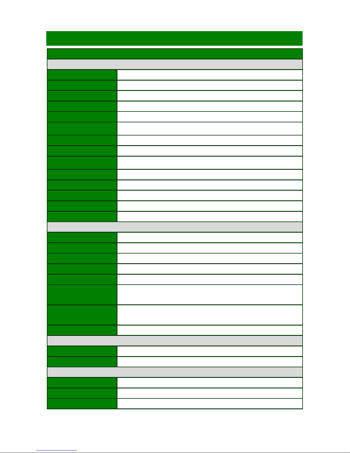
Specifications
System
CPU
Supports Intel® FCBGA8 45nm Atom™ N270 Processor
FSB
533 MHz
BIOS
Award 4MB (Mega Byte) SPI BIOS
System Chipset
Intel® 945GSE + ICH7-M Chipset
I/O Chipset
Winbond W83627DHG-A
Memory
One 200-pin SO-DIMM up to 2GB single Channel DDR2 533 SDRAM ,
non-ECC
SSD
One CompactFlash Type I/II socket
Watchdog Timer
Reset: 1 sec.~255 min. and 1 sec. or 1 min./step
H/W Status Monitor
Monitoring CPU temperature, voltage, and cooling fan status. Auto throttling
control when CPU overheats
Expansion Slots
1 x PCI (PCI Rev. 2.3 compliant) supports 3 PCI master
DIO
8-bit General Purpose I/O for DI and DO
S3/S4
Yes
TPM
TPM1.2 (Infineon® TPM chip 9635 TT 1.2 on board)LAN (PME / RPL)
Wake up on LAN or Ring
YES
Display
Chipset
Intel® 945GSE GMCH integrated Graphics Media Accelerator 950
Display Memory
Intel® DVMT 3.0 supports 224 MB video memory
Max Resolution
CRT mode :2048x1536@75Hz , LCD mode : 2048x1536@60Hz
Dual Display
Dual view, 2-CH LVDS, DVI
VGA
Yes , on board GMA 950,Support for CRT resolutions up to QXGA
LVDS
Support for dual-channel LVDS resolutions up to UXGA
18bit Single/Dual channel
LVDS Backlight power
connector
Yes
DVI
Yes
Networking
LAN1
Realtek RTL8111C Gigabit LAN
LAN2
Realtek RTL8111C Gigabit LAN
Audio
Audio Codec
Realtek® ALC888, 5.1 HD Audio
Audio Interface
Mic in, Line in, Line out
Audio Amplifier (W)
TPA3005D2 Stereo 6Watt
MX945GSE3 Specifications Summary
Page 9

MX945GSE3 User’s Manual
9
I/O Port
Back Panel I/O Port
1 x PS/2 Keyboard, 1 x PS/2 Mouse, 1 x VGA port, 1 x DVI port, 2 x COM
Port,
2 x RJ45 port, 4 x USB 2.0/1.1, 1 x Audio Jack (3 ports)
Internal I/O
2 x Power COM port, 1 x 2x10-pin ATX power connector, 1 x CPU fan
connector, 1 x Power fan connector, 1 x USB connectors support additional
2 USB ports, 1 x LVDS connector, 1 x LVDS inventor connector, 1 x IDE
connector, 2 x SATA connectors, 1 x Digital IO header, 1 x Front panel
header,
1 x S/PDIF Out header, 1 x Audio amplifier connector, 1 x Front audio
connector, 1 x Mini-PC I Express
Mechanical & Environment
Power Type
ATX mode
Operating Temp.
0 ~ 60℃ (32 ~ 140℉)
Operating Humidity
0%~90% relative humidity, non-condensing
Size (L x W)
170 mm x 170 mm
* Specifications are subject to change without notice.
Page 10

MX945GSE3 User’s Manual
10
Chapter 1
This chapter describes the motherboard features and the new technologies it supports.
Product Introduction
Page 11

MX945GSE3 User’s Manual
11
1.1 Welcome!
Thank you for buying an ® MX945GSE3 motherboard!
The motherboard deli v er s a host of new features and latest technologi es, making it another
standout in the long line of quality motherboards!
Before you start installing the motherboard, and hardware devices on it, check the items in
your package with the list below.
1.2 Package contents
Check your motherboard package for the following items.
Before you begin inst alling your single boar d, pl ease mak e su r e th at the following mater ial s
have been shipped:
1 x MX945GSE3 Mini ITX Main board
1 x CD-ROM contains the followings:
• User’s Manual in PDF file
• Drivers
1 x IDE cable (40-pin)
2 x SATA cable kit (SATA/Power)
1 x I/O Shield
1 x Startup Manual
If any of the above items is damaged or missing, contact your
retailer.
Page 12

MX945GSE3 User’s Manual
12
1.3 Special features
1.3.1 Product highlights
The Latest Processor Technology
The Intel® Atom™ processor is Intel's smallest processor, built with the world's smallest
transistors and manufactured on Intel's industry-leading 45nm Hi-k Metal Gate technology.
The Intel Atom processor was purpose-b ui l t for simple, affordable, netbooks and net t ops.
Intel® Atom™ N270 Processor
The Intel® Atom™ processor N270, implemented in 45nm technology, is power-optimized
and delivers robust performance-per-watt for cost-effective embedded solutions. Featuring
extended lifecycle support, this processo r o f fer s an excellent solution for e mbe dded market
segments such as digital signage, interactive clients (kiosks, point-of-sale terminals), thin
clients, digital security, residential gateways, print imaging, and commercial and industrial
control. The processo r r emai ns software compatibl e with previous 32-bit I nt el ® ar chitecture
and complementary silicon.
Intel® 945GSE Chipset
The mobile Intel® 945GSE Express Chipset provides power-efficient graphics and rich I/O
capabilities for cost-effective embedded solutions. It features an integrated 32-bit 3D
graphics engine based on Intel® Graphics Media Accelerator 950 (Intel® GMA 950)
architecture, a 533 MHz front-side bus (FSB), single-channel 400/533 MHz DDR2 system
memory (SODIMM and/or memory down), and Intel® High Definition Audio¹ interface.
The chipset consists of the Intel® 82945GSE Graphics Memory Controller Hub (GMCH)
and Intel® I/O Controller Hub 7-M (ICH7-M). It delivers outstanding system performance
and flexibility through high-bandwidth interfaces such as PCI Express,* PCI, Serial ATA,
and Hi-Speed USB 2.0 connectivity.
DDR2 memory support
The motherboard supports DDR2 memory which features data transfer rates of
1066/800/533 MHz to meet the higher bandwidth requirements of the latest 3D graphics,
multimedia, and Internet applications. The dual-channel DDR2 architecture doubles the
bandwidth of your system memory to boost system performance, eliminating bottlenecks
with peak bandwidths of up to 8.5 GB/s.
PCI Express™ interface
The motherboard fully supports PCI Express, the latest I/O interconnect technology that
speeds up the PCI bus. PCI Express features point‑to‑point serial interconnections
between devices and allows higher clockspeeds by carrying data in packets. This high
Page 13

MX945GSE3 User’s Manual
13
speed interface is software compatible with existing PCI specifications. See page 1-22 for
details.
Serial ATA technology
The motherboard supports the Serial ATA technology through the Serial ATA interfaces
and the Intel® ICH7 ch ipset. The S A TA speci fi cation all ows for thinner, more flex ible ca bles
with lower pin count, reduced voltage requirement, and up to 300 MB/s data tr ansfer rate.
S/PDIF digital sound ready
The motherboard supports the S/PDIF Out function through the S/PDIF interfaces at
mainboard. The S/PDIF technology turns your computer into a high-end entertainment
system with digital connectivity to powerful audio and speaker systems. See page 1-31 for
details.
Temperature, fan, and voltage monitoring
The CPU temperature is monitored by the ASIC (integrated in the Winbond Super I/O) to
prevent overheating and damage. The system fan rotations per minute (RPM) is monitored
for timely failure detection. The ASIC monitors the voltage levels to ensure stable supply of
current for critical components.
Page 14

MX945GSE3 User’s Manual
14
1.4 Before you proceed
Take note of the following precautions before you install motherboard components or
change any motherboard settings.
Unplug the power cord from the wall socket before touching
any component.
Use a grounded wrist strap or touch a safely grounded object
or a metal
object, such as the power supply case, before
handling components to avoid damaging them due to static
electricity
Hold components by the edges to avoid touching the ICs on
them.
Whenever you uninstall any component, place it on a
grounded antistatic
pad or in the bag that came with the
component.
Before you install or remove any component, ensure that
the ATX power supply is switched off or the power cord is
detached from the power supply.
Failure to do so may
cause severe damage to the motherboard, peripheral s, and/o r
components.
Page 15
MX945GSE3 User’s Manual
15
1.5 Motherboard overview
Before you install the motherboard, study the configuration of your chassis to ensure that
the motherboard fits into it.
Make sure to unplug the power cord before installing or removing
the motherboard. Failure to do so can cause you physical injury and
damage motherboard comp on ents.
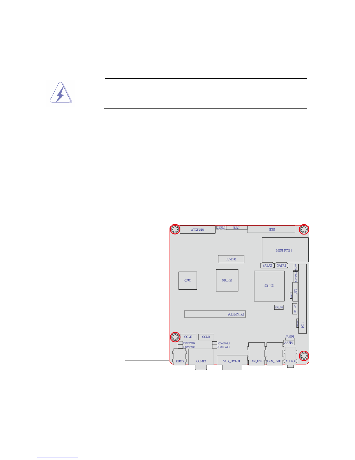
1.5.1 Placement Direction
When installing the motherboard, make sure that you place it into the chassis in the correct
orientation. The edge with external ports goes to the rear part of the chassis as indicated in
the image below.
1.5.2 Scre w Ho le s
Place four (4) screws into the holes indicated by circles to secure the motherboard to the
chassis.
Place this side towards
the rear of the chassis
Page 16
MX945GSE3 User’s Manual
16
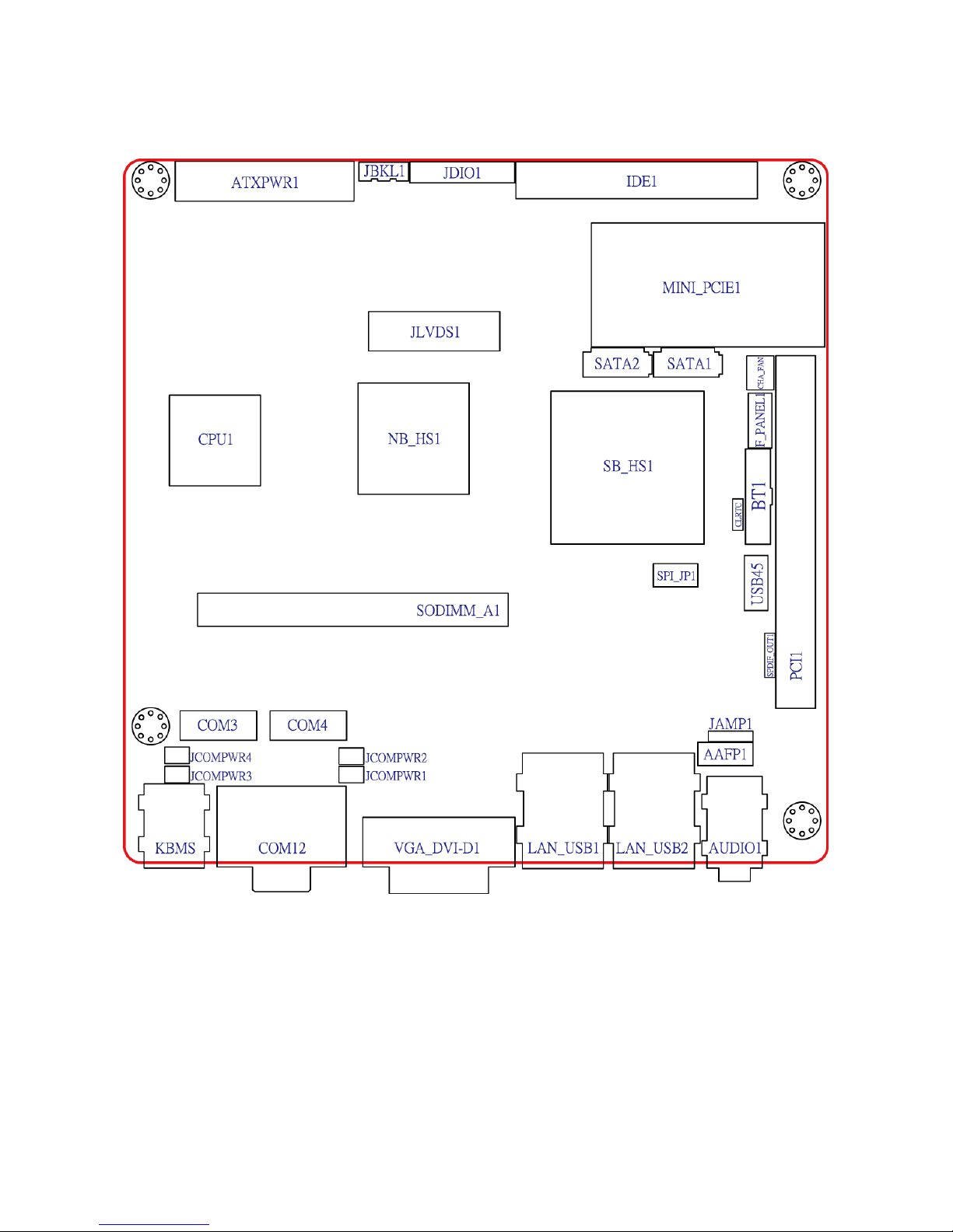
1.5.3 Motherboard Layout
Page 17
MX945GSE3 User’s Manual
17
1.6 System memory
1.6.1 Overview
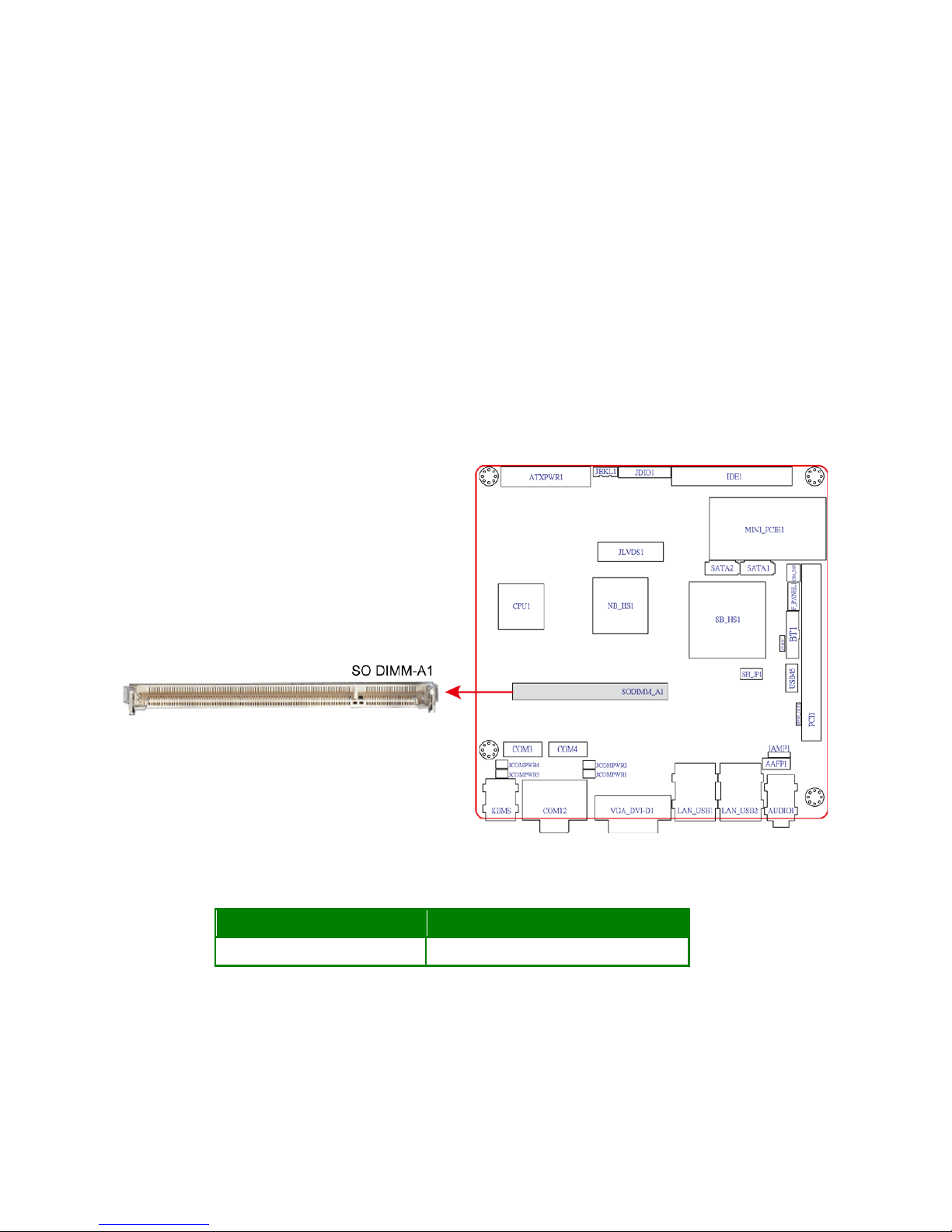
The motherboard comes with one 200-pin Double Data Rate 2 (DDR2) Small Outline Dual
Inline Memory Modules (SO-DIMM) sockets.
A DDR2 module has the same physical dimensions as a DDR DIMM but has a 200-pin
footprint compared to the 184-pin DDR DIMM. DDR2 DIMMs are notched differently to
prevent installation on a DDR DIMM socket. The following figure illustrates the location of
the sockets:
200-Pin DDR2 SO-DIMM sockets
Channel Socket
Channel A SO DIMM_A1
1.6.2 Memory Configurations
You may install 64 MB, 128 MB, 256 MB, 512 MB and 1 GB unbuffered ECC or non-ECC
DDR SO-DIMMs into the SO-DIMM sockets using the memory configurations in this
section.
Page 18

MX945GSE3 User’s Manual
18
1.6.3 Installing a DIMM
Make sure to unplug the power supply before adding or removing
SO-DIMMs or other system components. Failure to do so may cause
severe damage to both the motherboard and the components.
1. Unlock a SO-DIMM socket by pressing the retaining clips outward
2. Align a SO-DIMM on the socket such that the notch on the SO-DIMM matches the
break on the socket.
3. Firmly insert the SO-DIMM into the socket until the retaining clips snap back in place
and the SO-DIMM is properly seated.
A DDR2 SO-DIMM is keyed with a notch so that it fits in only one
direction. DO NOT force a SO-DIMM into a socket to avoid
damaging the SO-DIMM.
The DDR2 SO-DIMM sockets do not support DDR SO-DIMMs. DO
NOT install DDR SO-DIMMs to the DDR2 SO-DIMM socket.
1.6.4 Removing a SO-DIMM
1. Simultaneously press the retaining clips outward to unlock the SO-DIMM.
Support the SO-
DIMM lightly with your fingers when pressing the
retaining clips. The SO-DIMM might get damaged when it flips out with
extra force.
2. Remove the SO-DIMM from the socket.
1.7 Expansion slots
In the future, you may need to install expansion cards. The following sub-sections describe
the slots and the expansion cards that they support.
Make sure to unplug the power cord before adding or removing
expansion cards. Failure to do so may cause you physical injury and
damage motherboard comp on ents.
Page 19
MX945GSE3 User’s Manual
19
1.7.1 Installing an Expansion Card
1. Before installing the expansion card, read the documentation that came with it and
make the necessary hardware settings for the card.
2. Remove the system unit cover (if your motherboard is already installed in a chassis).
3. Remove the bracket opposite the slot that you intend to use. Keep the screw for later
use.
4. Align the card co nnec tor w ith the slot a nd pr ess firml y unti l the ca rd i s compl etel y seated
on the slot.
5. Secure the card to the chassis with the screw you removed earlier.
6. Replace the system cover.
1.7.2 Configuring an Expansion Ca rd
After installing the expansion card, configure it by adjusting the software settings.
1. Turn on the system and change the necessary BIOS settings, if any. See Chapter 2 for
information on BIOS setup.
2. Assign an IRQ to the card if needed. Refer to the tables on the next page.
3. Install the software drivers for the expansion card.
1.7.3 PCI slots
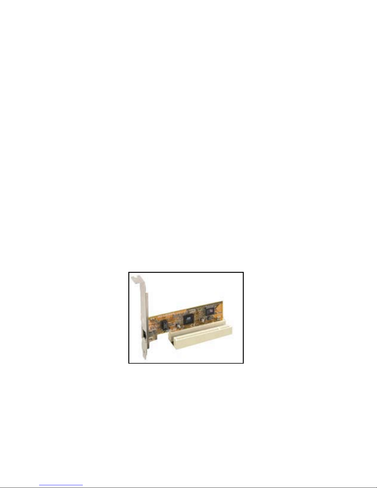
The PCI slots support cards such as a LAN card, SCSI card, USB card, and other cards
that comply with PCI specifications. The figure shows the type of LAN card that can be
installed on a PCI slot.
Page 20
MX945GSE3 User’s Manual
20
1.8 Jumpers
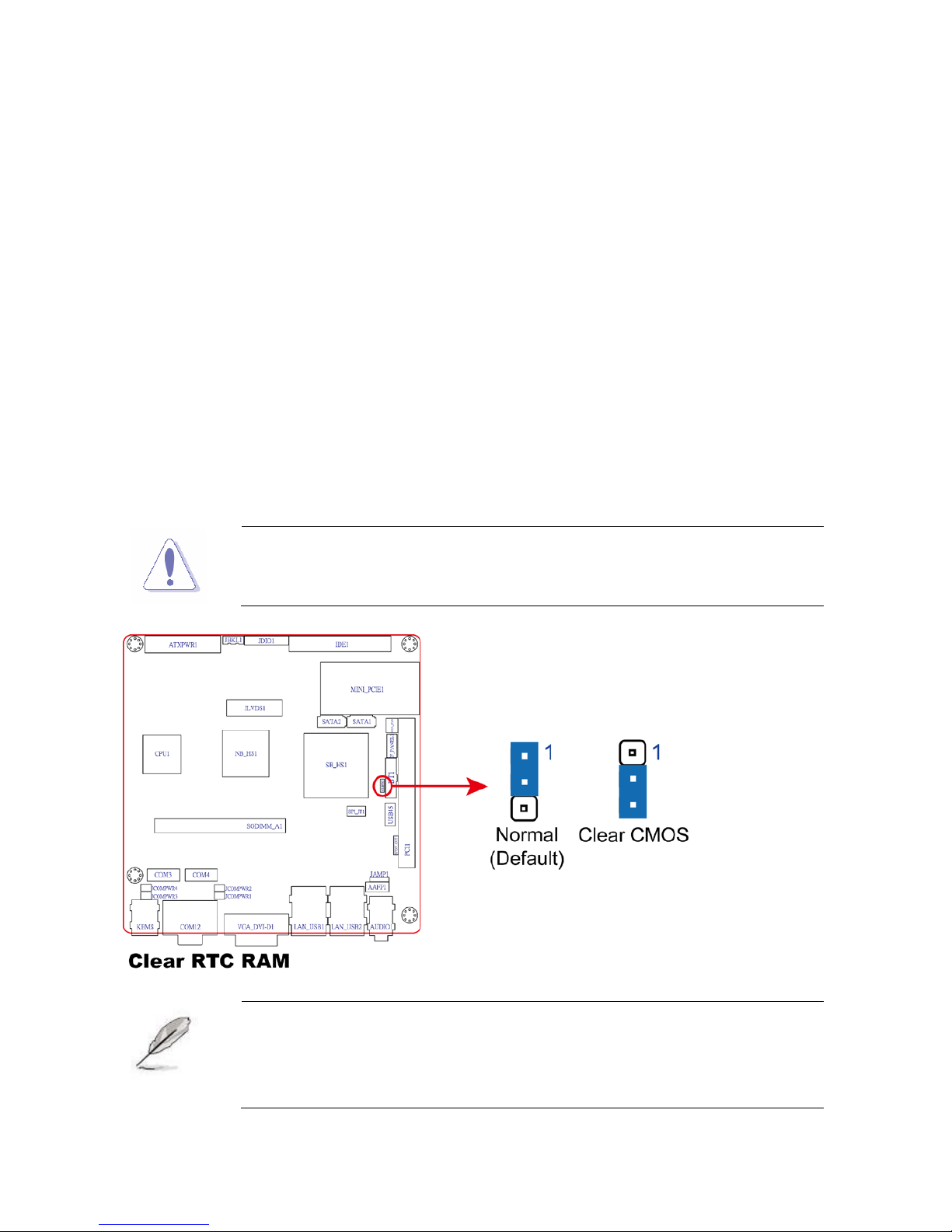
1. Clear RTC RAM (CLRTC)
This jumper allows you to clear the Real Time Clock (RTC) RAM in CMOS. You can clear
the CMOS memory of date, t ime , an d system setup parameter s by erasing the CMOS RTC
RAM data. The onboard button cell battery powers the RAM data in CMOS, which include
system setup information such as system passwords.
To erase the RTC RAM:
1. Turn OFF the computer and unplug the power cord.
2. Remove the onboard battery.
3. Move the jumper cap from pins 1-2 (default) to pins 2-3. Keep the cap on pins 2-3 for
about 5~10 seconds, then move the cap back to pins 1-2.
4. Re-install the battery.
5. Plug the power cord and turn ON the computer.
6. Hold down the <Del> key during the boot process and enter BIOS setup to re-enter
data.
Except when clearing the RTC RAM, never remove the cap on CLRTC
jumper default position. Removing the cap will cause system boot failure!
You do not need to clear the RTC when the system hangs due to
overclocking. For system failure due to
overclocking, use the C.P.R.
(CPU Parameter Recall) feature. Shut down and reboot the system so
the BIOS can automatically reset parameter settings to default values.
Page 21
MX945GSE3 User’s Manual
21
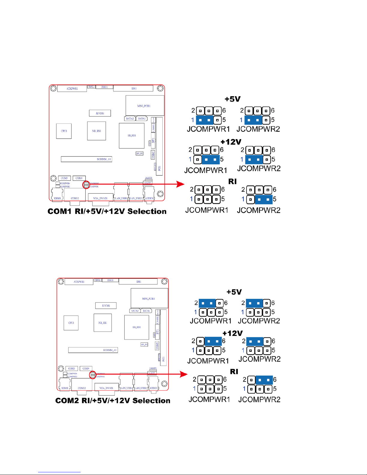
2. COM1 RI, +12V and +5V Power Select (JCOMPWR1, JCOMPWR2)
This jumper allows you to select COM1 RI, +5V and +12V power. Set JCOMPWR1 to pins
1-3 and JCOMPWR2 to pi ns 1-3 to select +5V pow er. And set JCOMPWR1 to pins 3-5 and
JCOMPWR2 to pins 1-3 to select +12V power. Then set JCOMPWR2 to pins 3-5 and
JCOMPWR1 to open for RI selection.
3. COM2 RI, +12V and +5V Power Select (JCOMPWR1, JCOMPWR2)
This jumper allow s y ou to selec t C OM2 RI, +5V and +12V pow er . Set JCOM P WR1 to pins
2-4 and JCOMPWR2 to pins 2-4 to select +5V power. And set JCOMPWR1 to pins 4-6
and JCOMPWR2 to pins 2-4 t o s el ec t + 12 V power. Then set JCOM PWR2 to pins 4-6 and
JCOMPWR1 to open for RI selection.
Page 22
MX945GSE3 User’s Manual
22
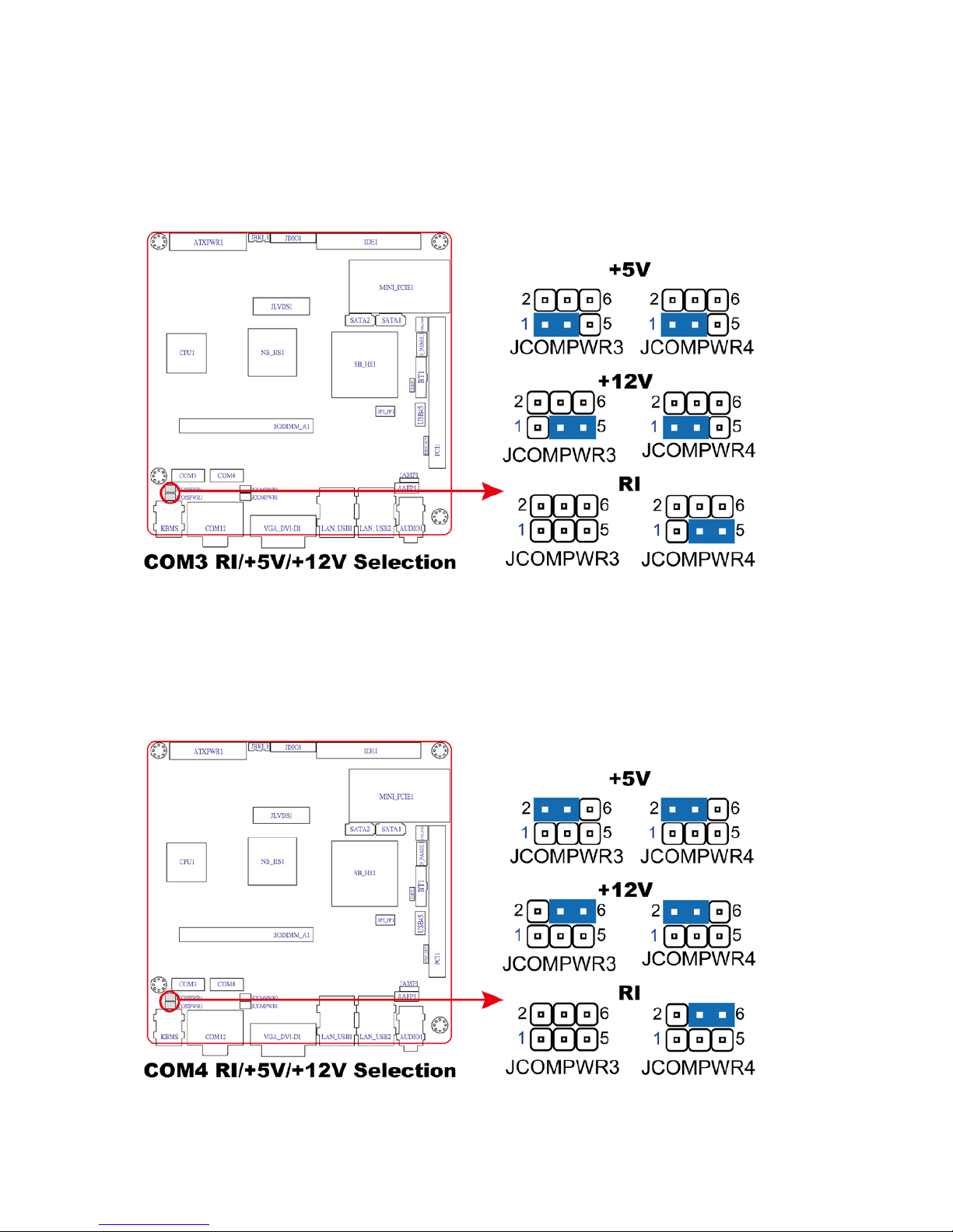
4. COM3 RI, +12V and +5V Power Select (JCOMPWR3, JCOMPWR4)
This jumper allow s y ou to selec t C OM3 RI, +5V and +12V pow er . Set JCOM P WR3 t o pins
1-3 and JCOMPWR4 to pins 1-3 to select +5V power. And set JCOMPWR3 to pins 3-5
and JCOMPWR4 to pins 1-3 to sel ect + 12 V power. Then set JCOM PWR4 to pins 3-5 and
JCOMPWR3 to open for RI selection.
5. COM4 RI, +12V and +5V Power Select
(JCOMPWR3, JCOMPWR4)
This jumper allow
s you to select C OM3 RI, +5 V and +12V p ower . Set JCOM P WR3 to pins
2-4 and JCOMPWR4 to pins 2-4 to select +5V power. And set JCOMPWR3 to pins 4-6
and JCOMPWR4 to pins 2-4 t o s el ect + 12 V power. Then set JCOM PWR4 to pins 4-6 and
JCOMPWR3 to open for RI selection.
Page 23
MX945GSE3 User’s Manual
23
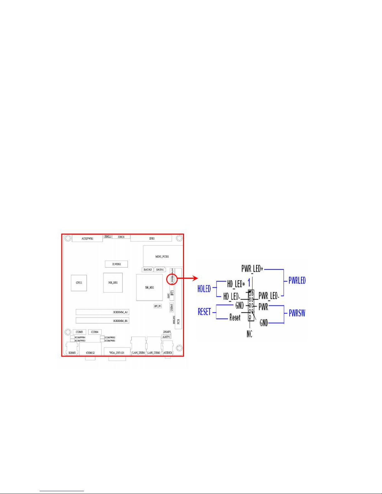
6. System Panel Connector (F_PANEL1)
This connector supports several chassis-mounted functions .
System Power LED (2-pin PWRLED)
This 2-pin connector is for the system power LED. Connect the chassis power LED
cable to this connector. The system power LED lights up when you turn on the system
power, and blinks when the system is in sleep mode.
ATX Power Button/Soft-off Button (2-pin PWRSW)
This connector is for the system power button. Pressing the power button turns the
system on or puts the system in sleep or soft-off mode depending on the BIOS settings.
Pressing the power switch for mor e tha n f our se conds while the system is ON turns the
system OFF.
Hard Disk Drive Activity LED (2-pin HDLED)
This 2-pin connector is for the HDD Activity LED. Connect the HDD Activity LED cable
to this connector. The IDE LED lights up or flashes when data is read from or written to
the HDD.
Reset Button (2-pin RESET)
This 2-pin connector is for the chassis-mounted reset button for system reboot without
turning off the syst em power.
Page 24
MX945GSE3 User’s Manual
24
1.9 Connectors
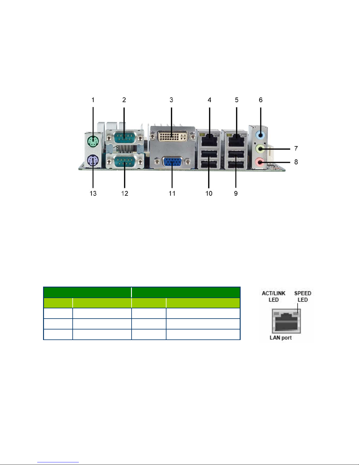
1.9.1 Rear panel connectors
1. PS/2 mouse port (green). This port is for a PS/2 mouse.
2. Serial connector. This 9-pin COM1 port is for serial devices.
3. DVI connector. This 24-pin DVI port connects to a DVI monitor.
4 & 5. LAN (RJ-45) port. This port allow s Gi gabi t connec ti on to a Loca l Area Network (LAN)
through a network hub. Refer to the table below for the LAN port LED indications.
LAN port LED indications
6. Line In port (light blue). This port connects a tape, CD, DVD player, or other audio
sources.
7. Line Out port (lime). This port connects a headphone or a speaker. In 4-channel,
6-channel, and 8-channel configuration, the function of this port becomes Front Speaker
Out.
8. Microphone port (pink). This port connects a microphone.
9. USB 2.0 ports 3 and 4. These two 4-pin Universal Serial Bus (USB) ports are available
for connecting USB 2.0 devices.
ACT/ LINK LED SPEED LED
Status Description Status Description
OFF No link OFF 10Mbps connection
Orange Linked Orange 100Mbps connection
Blinking Data activity Green 1Gbps connection
Page 25
MX945GSE3 User’s Manual
25
10. USB 2.0 ports 1 and 2. These tw o 4-pin Universal Ser ial Bus (USB) ports are av ail able
for connecting USB 2.0 devices.
11. VGA port. This 15-pin VGA port connects to a VGA monitor.
12. Serial connector. This 9-pin COM2 port is for serial devices.
13. PS/2 keyboard port (purple). This port is for a PS/2 keyboard.
1.9.2 Internal connectors
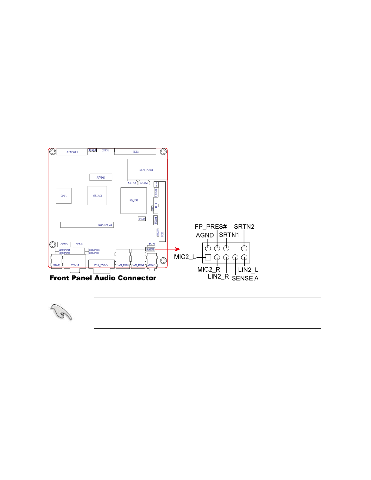
1. Front panel audio connector (10-pin AAFP1)
This connector is for a chassis-mounted front panel audio I/ O mod ule that supports either
HD Audio or legacy AC’97 audio standard.
It is recommended that you connect a high-definition front panel audio
module to this connector to avail of the motherboard’s high‑definition
audio capability.
Page 26
MX945GSE3 User’s Manual
26
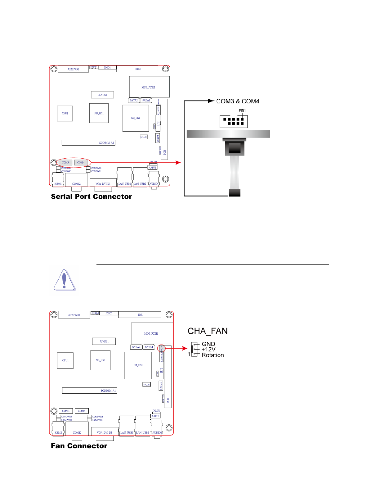
2. Serial Port connectors (9-pin COM3, COM4)
This connector is for a serial (COM) port. Connect the serial port module cable to this
connector, then inst all the modul e to a slot opening at the back of the system chassis.
3. CPU, Power and Chassis fan connectors (3-pin CH A_FAN)
The fan connectors support cooling fans of 350mA~740mA (8.88W max.) or a total of
1A~2.22A (26.64W max.) at +12V. Connect the fan cables to the fan connectors on the
motherboard, making sure that the black wire of each cable matches the ground pin of the
connector.
Do not forget to connect the fan cables to the fan connectors. Insufficient
air
flow inside the system may damage the motherboard components.
These are not jumpers! DO NOT place jumper c
aps on the fan
connectors.
Page 27
MX945GSE3 User’s Manual
27
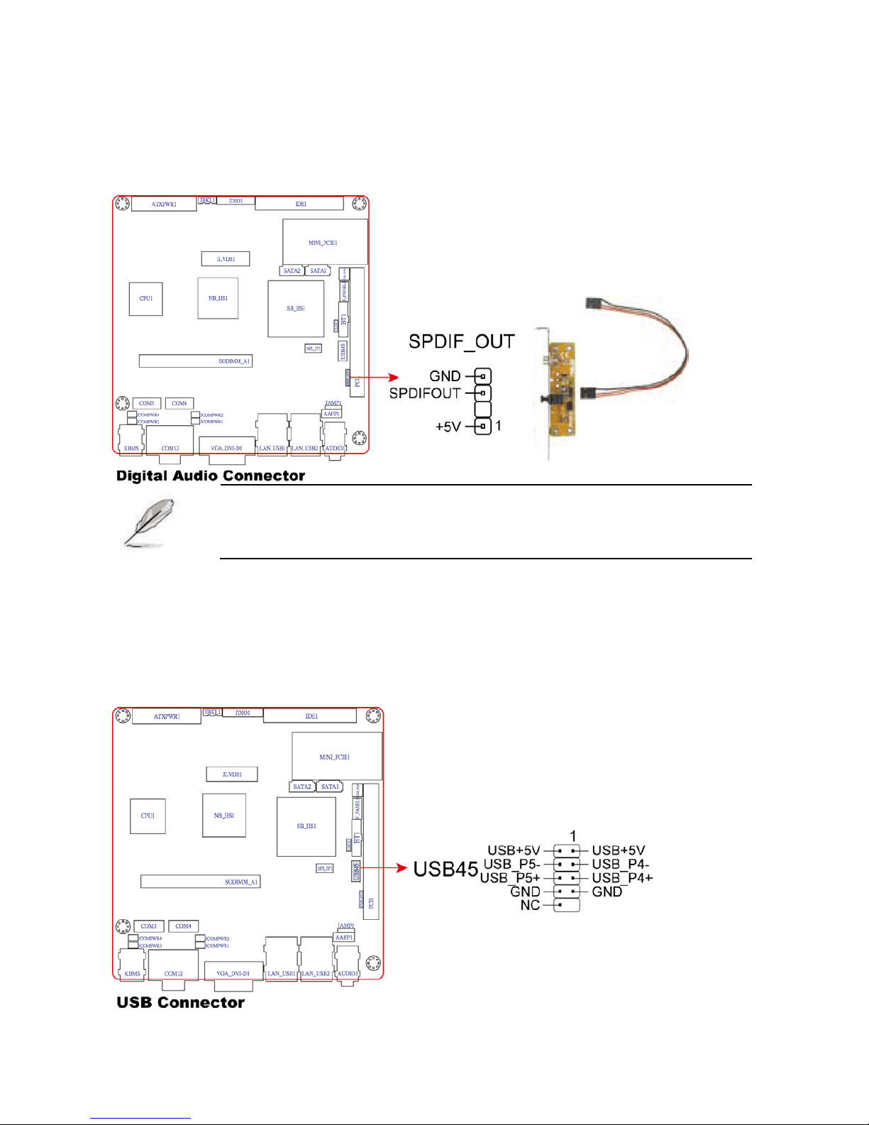
4. Digital Audio connector (4-1 pin SPDIF_OUT)
This connector is for the S/PDIF audio module to allow digital sound output.
Connect one end of the S/PDIF audio cable to this connector and the other end to the
S/PDIF module.
The S/PDIF out module is purchased separately.
5. USB connectors (10-1 pin USB45)
This connector is for USB 2.0 ports. Connect the optional USB module cable to any of
these connectors, then install the module to a slot opening at the back of the system
chassis. These USB connectors comply with USB 2.0 specification that supports up to 480
Mbps connection speed.
Page 28
MX945GSE3 User’s Manual
28
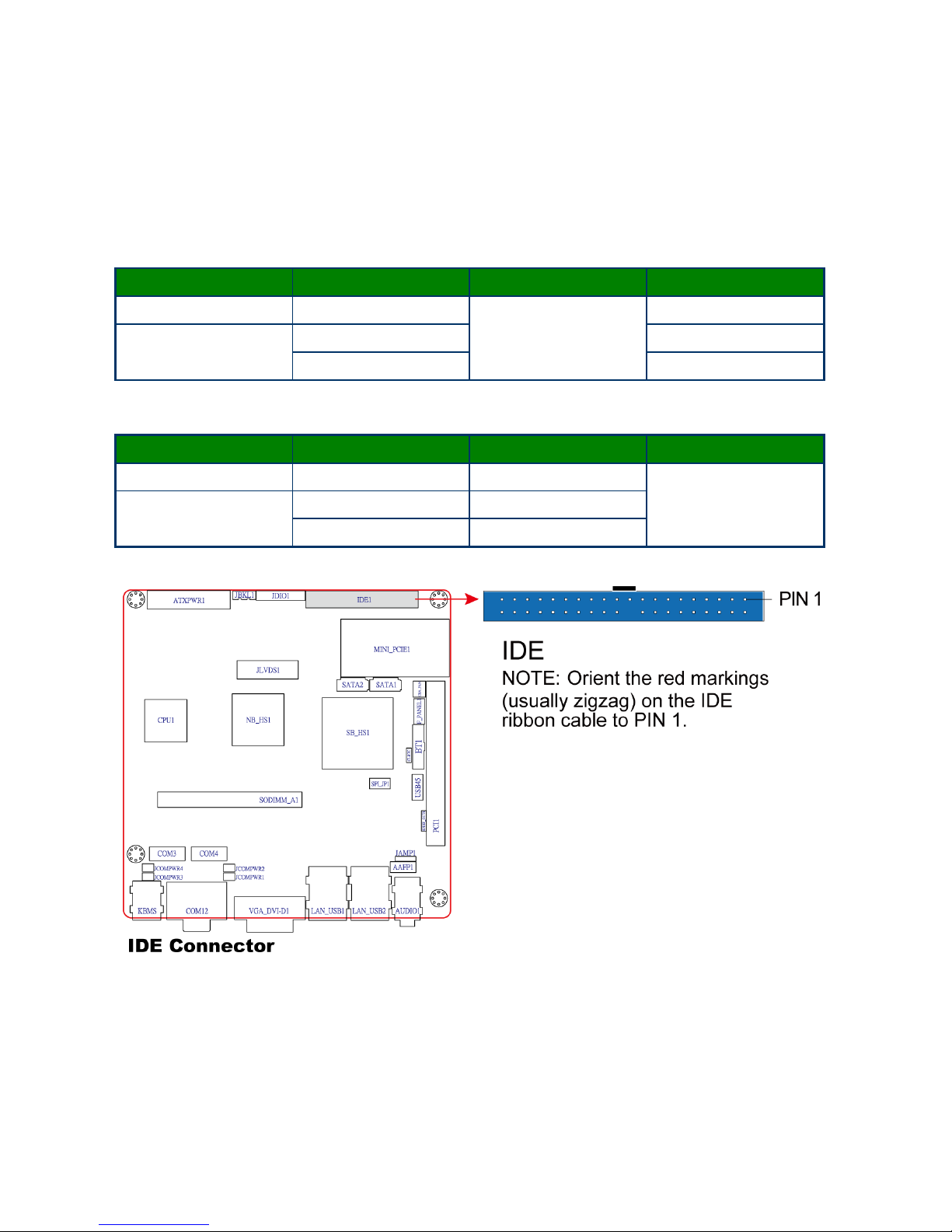
6. Primary IDE connector (40-1 pin IDE1)
These connectors are for Ultra DMA 133/100/66 signal cables. There are three interfaces
on each Ultra DMA 133/10 0/6 6 sig nal ca ble: blue, black, and gray.
Connect the blue interface into the motherboard’s IDE connector, then select one of the
following modes to configure your hard disk drive(s).
Cable Select Mode - use this mode to select the operating mode by cable connectors.
No. of drives Drive type Drive jumper Cable connector
1 With OS
Cable select
black
2
With OS black
Without OS gray
Jumper Select Mode - use this mode to select the operating mode by hard disk drive
jumper.
No. of drives Drive type Drive jumper Cable connector
1 With OS Master
black or gray
2
With OS Master
Without OS Slave
Page 29
MX945GSE3 User’s Manual
29
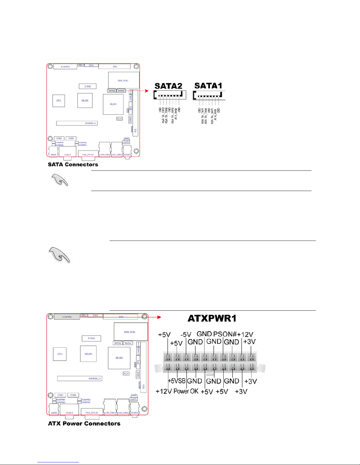
7. Serial ATA connectors
(7-pin SATA1, SATA2)
These connectors are for the Serial ATA signal cables for Serial ATA hard disk drives.
Install the Windows® 2000 Service Pack 4 or the Windows® XP Service
Pack1 or later before using Serial ATA.
8. ATX power connectors (20-pin ATXPWR1)
The connector is for ATX power supply plugs. The power supply plugs are designed to fit
these connectors in only one orientation. Find the proper orientation and push down firmly
until the connectors completely fit.
Use of a PSU with a hig her pow er output i s reco mmende d w hen
configuring a system with more power-consuming devices. The
system may become unstable or may not boot up if the power is
inadequate.
Make sure that your power supply unit (PSU) can provide at
least the minimum power required by your system. See the
table below for details.
Page 30
MX945GSE3 User’s Manual
30
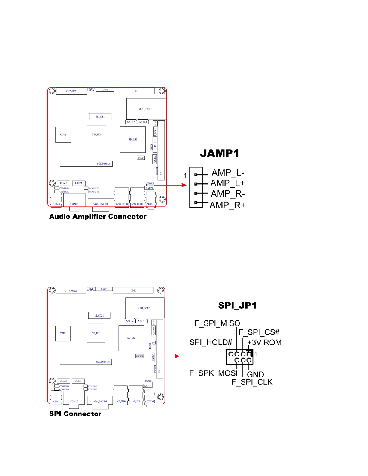
9. Audio Amplifier connectors (4-pin JAMP1)
An amplifier connector is an electronic amplifier that amplifies low-power audio signals
(signals composed primarily of frequencies between 20 hertz to 20,000 hertz, the human
range of hearing) to a level suitable for driving loudspeakers and is the final stage in a
typical audio playback chain.
10. SPI Connector (7-pin SPI_JP1)
It is a point-to-point interface standard, allows network equipment designers to develop an
array of next-generation multi-service switches and routers to support multi-service traffic
with aggregate bandwidths up to OC-192 (10 Gb/s) and beyond, enabling them to
dramatically increase system performance.
Page 31
MX945GSE3 User’s Manual
31
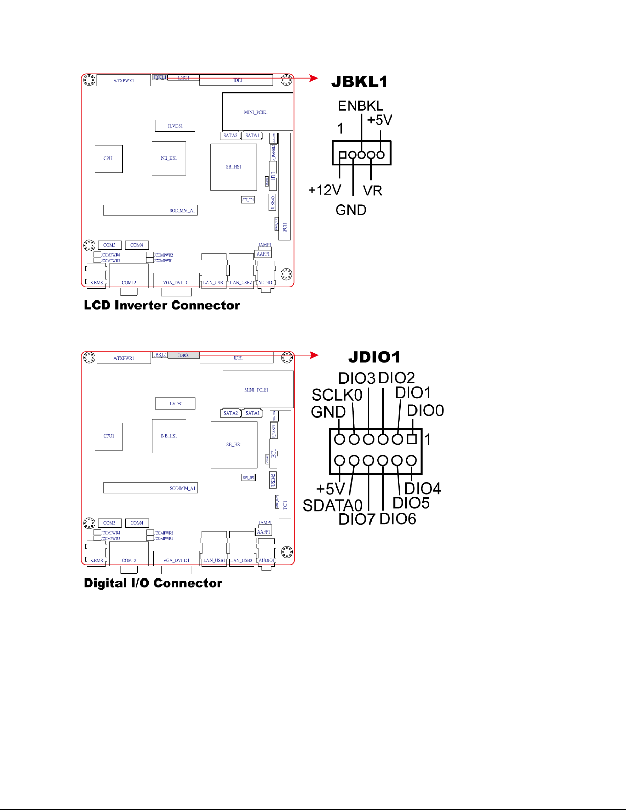
11. LCD Inverter Connector (5-pin JBLK)
12. Digital IO Connector (12-pin JDIO)
Page 32
MX945GSE3 User’s Manual
32
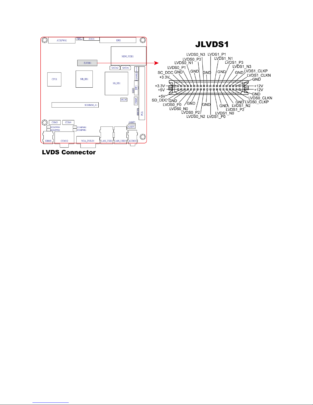
13. LVDS Connector (40-pin JLVDS)
Page 33

MX945GSE3 User’s Manual
33
Chapter 2
This chapter tells how to change the system settings through the BIOS Setup menus.
Detailed descriptions o f the BIO S par am eter s are also pr ovided.
BIOS Setup
Page 34

MX945GSE3 User’s Manual
34
2.1 Managing and updating your BIOS
2.1.1 Creati ng a boota ble floppy disk
1. Do either one of the following to create a bootable floppy disk.
a. Insert a 1.44MB floppy disk into the dirve.
DOS environment
b. At the DOS prompt, type format A:/S then press <Enter>.
a. Insert a 1.44 MB floppy disk to the floppy disk drive.
Windows® XP environment
b. Click Start from the Windows® desktop, then select My Computer.
c. Select the 3 1/2 Floppy Drive icon.
d. Click File from the menu, then select Format. A Format 3 1/2 Floppy Disk
window appears.
e. Select Create an MS-DOS startup disk from the format opti ons fi el d, then click
Start.
a. Insert a formatted, high density 1.44 MB floppy disk into the drive.
Windows® 2000 environment
To create a set of boot disks for Windows® 2000:
b. Insert the Windows® 2000 CD to the optical drive.
c. Click Start, then select Run.d. From the Open field, type
D:\bootdisk\makeboot a:
assuming that D: is your optical drive.
d. Press <Enter>, then follow screen instructions to continue.
2. Copy the original or the latest motherboard BIOS file to the bootable floppy disk.
Page 35

MX945GSE3 User’s Manual
35
2.2 BIOS setup program
This motherboard supports a programmable firmware chip that you can update u sing the
provided utility described in section “2.1 Managing and updating your BIOS.”
Use the BIOS Setup program when you are installing a motherboard, reconfiguring your
system, or prompted to “Run Setup”. This section explains how to configure your sy stem
using this utility.
Even if you are not prompted to use the Setup program, you can change the configuration
of your computer in the future. For example, you can enable the security password feature
or change the power management settings. This requires you to reconfigure your system
using the BIOS Setup program so that the computer can recognize these changes and
record them in the CMOS RAM of the firmware hub.
The firmware hub on the motherboard stores the Setup utility. When you start up the
computer, the system provides you with the opportunity to run this program.
Press <Del> during the Power-On-Self-Test (POST) to enter the Setup utility; otherwise,
POST continues with its test routines.
If you wish to enter Setup after POST, restart the system by pressing <Ctrl+Alt+Delete>, or
by pressing the reset button on the system chassis. You can also restart by turning the
system off and then back on. Do this last option only if the first two failed.
The Setup progr am is designed to make it as easy to use as possible. Bei ng a menu-driven
program, it lets you scroll through the various sub-menus and make your selections from
the available options using the navigation keys.
The default BIOS settings for this motherboard apply for most
conditions
to ensure optimum performance. If the system
becomes unstable after changing any BIOS settings, load the
default settings to ensure system compatibility and stability.
Select the Load Default Settings item under the Exit Menu.
See section “2.7 Exit Menu.”
The BIOS setup screens shown in this section are for reference
purposes
only, and may not exactly match what you see on
your screen.
Visit the BCM website to download the latest BIOS file for this
motherboard.
Page 36

MX945GSE3 User’s Manual
36
2.2.1 Legend Box
The keys in the legend bar allow you to navigate through the various setup menus.
Key(s) Function Description
F1 General help, only for Status Page Setup Menu and Option Page
Setup Menu
Esc Return to the main menu from a sub-menu or prompts you to quit
the setup program
, Move to the item in the left or right hand
, Move to previous or next item
Enter Brings up a selection menu for the highlighted field
+ or PgUp Moves the cursor to the first field
- or PgDn Moves the cursor to the last field
F5 Loads the previous values
F6, F7 Loads the fail-safe / optimized defaults
F10 Saves changes and exits Setup
2.2.2 List Box
This box appears only in the opening screen. The box displays an initial list of configurable
items in the menu you selected.
2.2.3 Sub-menu
Note that a right pointer symbol () appears to the left of certain fields. This pointer
indicates that you can display a sub-menu from this field. A sub-menu contains additional
options for a field parameter. To display a sub-menu, move the highlight to the field and
press <Enter>. The sub-menu appears. Use the legend keys to enter values and move
from field to f ield within a sub-menu as you would within a menu. Use the <Esc> key to
return to the main menu.
Take some time to familiarize yourself with the legend keys and their corresponding
functions. Practice navigating through the various menus and submenus. If you
accidentally make unwanted changes to any of the fields, press <F6> to load the fail-safe
default values. While moving around through the Setup program, note that explanations
appear in the Item Specific Help window located to the right of each menu. This window
displays the help text for the currently highlighted field.
Page 37
MX945GSE3 User’s Manual
37
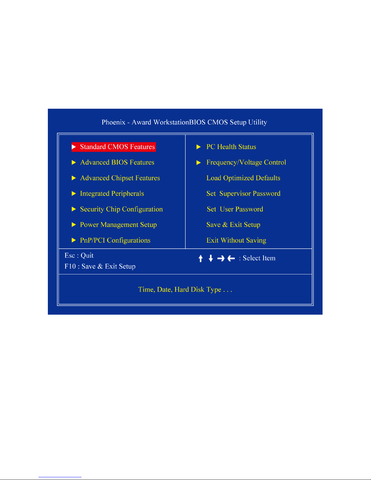
2.3 BIOS menu screen
When you enter the BIOS, the following screen appears. The BIOS menu screen displays
the items that allow you to make changes to the system configuration. To access the menu
items, press the up/down/right/left arrow key on the keyboard until the desired item is
highlighted, then press [Enter] to open the specific menu.
Page 38
MX945GSE3 User’s Manual
38
2.3.1 Standard CMOS Features
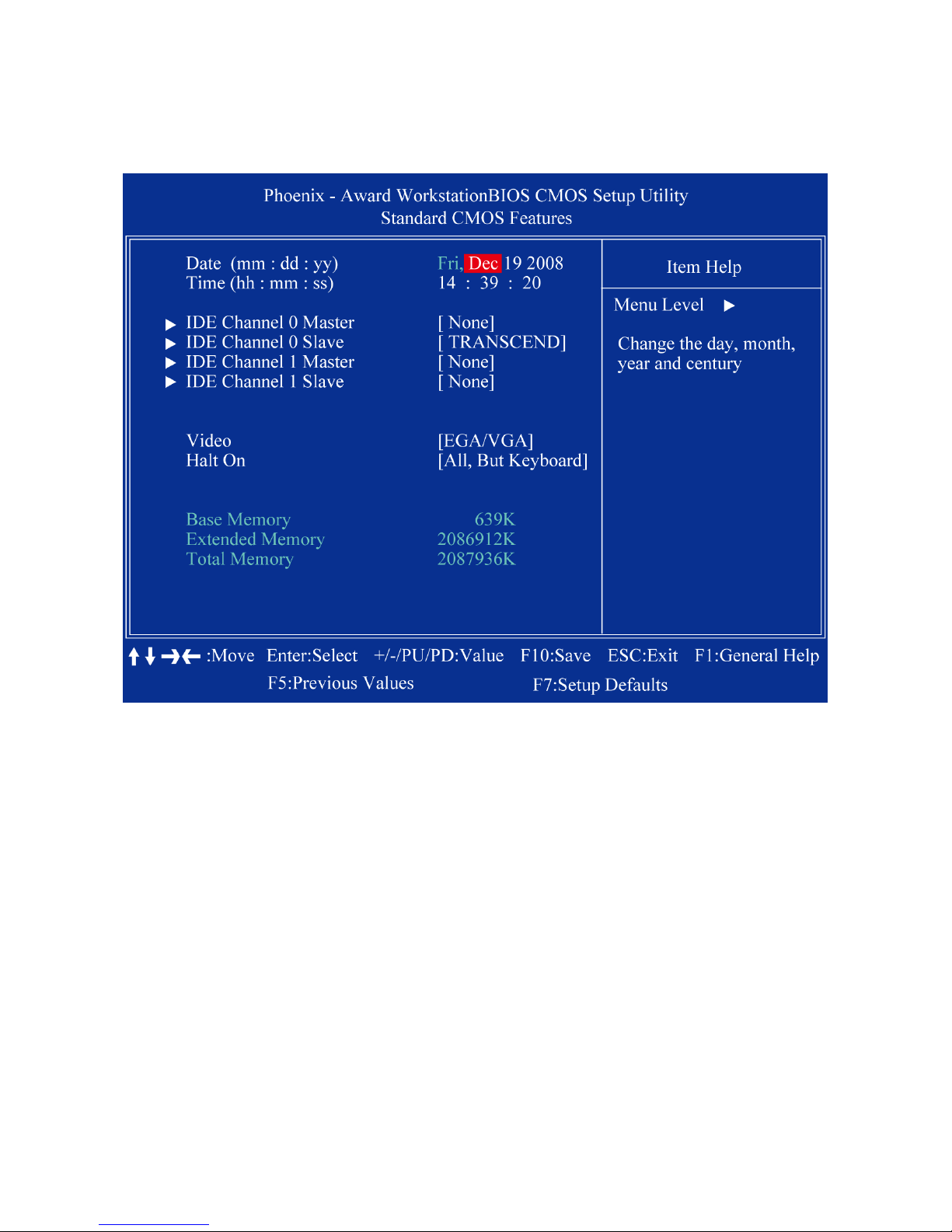
The Standard CMOS Features screen gives you an overview of the basic system.
2.3.1.1 Date [Day, xx/xx/xxxx]
The date format is <week>, <month>, <day>, <year>.
2.3.1.2 Time [xx:xx:xx]
The time format is <hour> <minute> <second>, based on the 24-hour clock.
2.3.1.3 IDE Channel 0/1 Master / Slave
IDE HDD Auto-Detection
[Press Enter] to select this option for automatic device detection.
IDE Device Setup
[Auto]: Automatically detects IDE devices during POST
[None]: Select this when no IDE device is used. The system will skip the
auto-detection setup to make system start up faster.
[Manual]: User can manually input the correct settings.
Access Mode: The options are CHS/LBA/Large/Auto
Capacity: Capacity of currently installed hard disk
Cylinder: Number of cylinders
Page 39

MX945GSE3 User’s Manual
39
Head: Number of heads
Precomp: Write precomp
Landing Zone: Landing zone
Sector: Number of sectors
2.3.1.4 Video
This category detects t he ty pe o f ada pter use d for the pr imary moni tor that m ust match your
video display card and monitor.
EGA / VGA: Enhanc ed G rap hics Ad apt er/Vid eo Gr aphics Ar ray . For EGA, VGA, SVGA ,
or PGA monitor adapters.
CGA 40: Color Graphics Adapter, power up in 40 column mode.
CGA 80: Color Graphics Adapter, power up in 80 column mode.
MONO: Monochrome adapter, includes high resolution monochrome adapters.
2.3.1.5 Halt On
Sets the system to halt on er rors acco rdi ng to the sy st em func tions s peci fied in e ach opti on.
Configuration options: [Al l Error s] [No Errors] [All, But Keyboard]
2.3.1.6 Memory
This category disp l ay s base me mor y , ex t ende d me mory, and total memory det ec t ed dur ing
POST (Power On Self Test).
Page 40
MX945GSE3 User’s Manual
40
2.3.2 Advanced BIOS Features
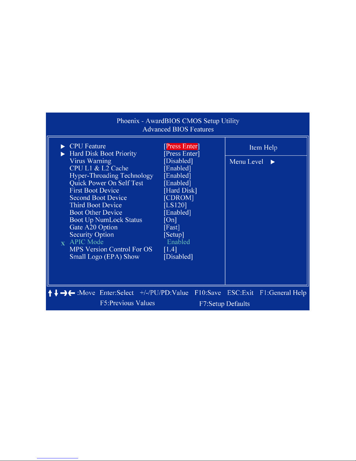
The “Advanced BIOS Features” screen appears when choosing the “Advanced BIOS
Features” item from the “Initial Setup Screen” menu. It allows the user to configure the
RX945G according to his particular requirements. Below are some major items that are
provided in the Advanced BIOS Features screen. A quick booting function is provided for
your convenience. Simply enable the Quick Booting item to save yourself valuable tim e.
Page 41
MX945GSE3 User’s Manual
41
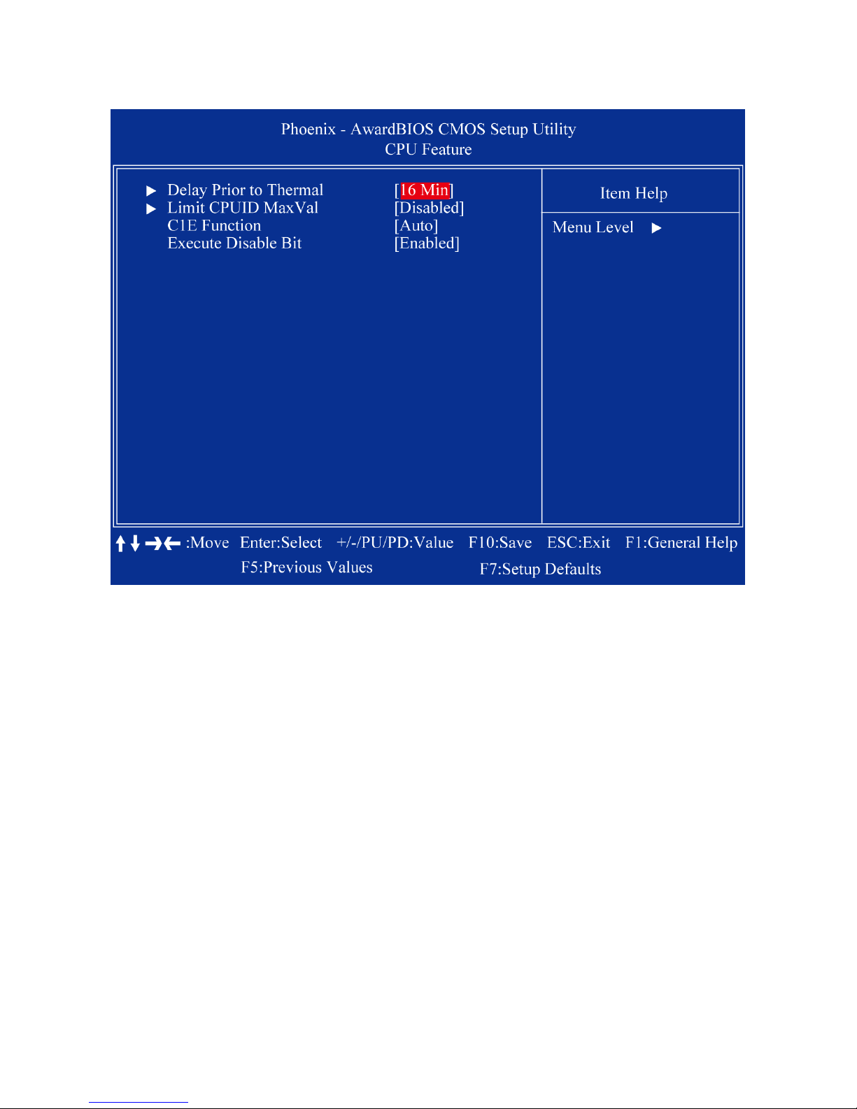
2.3.2.1 CPU Feature
Delay Prior to Thermal
The Delay Prior To Thermal BIOS feature controls the activation of the Thermal
Monitor's automatic mode. It allows you to determine when the Pentium 4's Thermal
Monitor should be activated in automatic mode after the system boots. For example,
with the default value of 16 Minutes, the BIOS activates the Thermal Monitor in
automatic mode 16 minutes after the system starts booting up.
Limit CPUID MaxVal
Set Limit CPUID MaxVa1 to 3. This should be disabled for WinXP
C1E Function
CPU C1E function select
Execute Disable Bit
When disabled, forces the XD featur e fl ag to always return 0
Page 42
MX945GSE3 User’s Manual
42
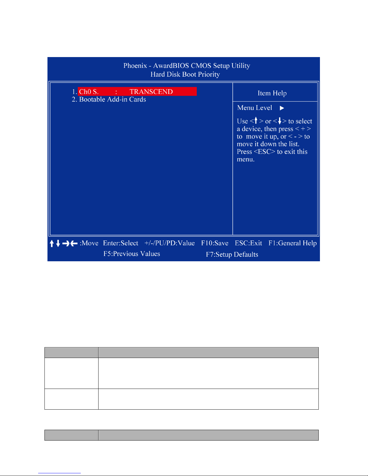
Hard Disk Boot Priority
Set hard disk boot device prior i ty.
CH0 S.
Primary SATA chan nel with Master Dev i ce. It will show the device model / ty pe when SATA
HDD or CD ROM connected.
Bootable Add-in Cards
"Bootable add-in cards" is an item on the HDD boot priority list.
2.3.2.2 Virus Warning
Enables or disables the virus warning.
Item Description
Enable
Activates automatically when the system boots up causing a warning
message to appear when anything attempts to access the boot sector
or hard disk partition table.
Disable
No warning message will appear when anything attempts to access the
boot sector or hard disk partition table.
2.3.2.3 CPU L1 & L2 Cache
Enabling this feature speeds up memory access.
Item Description
Page 43
MX945GSE3 User’s Manual
43
Enable Enable cache
Disable Disable cache
2.3.2.4 Hyper Threading Technology
System will detect automatically and show up when you installed the Intel® Pentium® 4
processor with HT Technology. Set to “Enabled” for faster system performance.
2.3.2.5 Quick Power On Se lf Test
This allows the system to skip certain tests to speed up the boot-up procedure.
Item Description
Enable Enable quick POST
Disable Normal P OST
2.3.2.6 First / Second / Third Boot Device
The BIOS tries to load the OS from the devices in the sequence set here. The options are:
Item Description
LS120 LS120 Device
HDD Hard Disk Device
CDROM CDROM Device
ZIP100 ZIP-100 Device
USB-FDD USB Floppy Device
USB-ZIP USB ZIP Device
USB-CDROM USB CDROM Device
USB-HDD USB Hard Disk Device
Legacy LAN Network Device
Disabled Disabled any boot device
2.3.2.7 Boot Other Device
Use this to boot another device. The options ar e “Ena bl ed” an d “Di sa bled” .
2.3.2.8 Boot Up NumLock Status
Sets the boot up Num Lock status. The options are “On” and “Off”.
Item Description
On Enable NumLock
Off Disable NumLock
2.3.2.9 Gate A20 Option
Item Description
Normal A pin in the keyboard controller controls GateA20
Fast Lets chipset control GateA20 (Default)
2.3.2.10 Security Option
This category determines whether the password is required when the sys- tem boots up or
only when entering setup. The options are:
Item Description
System The system will not boot and access to Setup will be denied if the
Page 44
MX945GSE3 User’s Manual
44
correct password is not entered at the prompt.
Setup
The system will boot, but access to Setup will be denied if the correct
password is not entered at the prompt.
To disable security, select PASSWORD SETTING at Main Menu and
then you will be asked to enter password. Do not type anything and just
press <Enter>, it will disable security. Once the security is disabled, the
system will boot and you can enter Setup freely.
2.3.2.11 APIC Mode
This setting allows you to enable the APIC mode. The choices are “Disabled” or “Enabled.”
2.3.2.12 MPS Version Control for OS
This option is only valid for multiprocessor motherboards as it specifies the version of the
Multiprocessor Specification (MPS) that the motherboard will use. The MPS is a
specification by which PC manufacturers design and build Intel architecture systems with
two or more processors.
MPS 1.1 was the original specification. MPS version 1.4 adds extended configuration
tables for improved support of multiple PCI bus configurations and greater expandability in
the future. In addition, MPS 1.4 introduces support for a secondary PCI bus without
requiring a PCI bridge.
2.3.2.13 Small Logo (EPA) Show
This item allows you enabled/disabled the small EPA logo show on screen at the POST
step.
Item Description
Enabled EPA Logo shows is enabled
Disabled EPA logo show is disabled
Page 45
MX945GSE3 User’s Manual
45
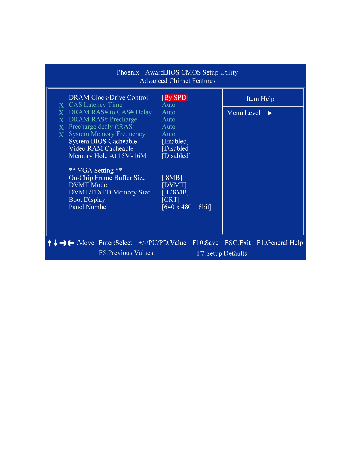
2.3.3 Advanced Chipset Features
2.3.3.1 DRAM Clock/Drive Control
When select to “BySPD”, the DRAM timing parameters are set according to DRAM SPD
(Serial Presence Detect). When disabled, one can manually set the DRAM timing
parameters through the sub items below. Set to “BySPD” if not sure.
2.3.3.2 CAS Latency Time
Controls the latency between the SDRAM Read command and the time data actually
becomes available.
2.3.3.3 DRAM RAS# to CAS# Delay
Controls the latency between the DDR SDRAM active command and the read/write
command.
2.3.3.4 DRAM RAS# Precharge
Controls the idle clocks after issuing a precharge command to the DDRSDRAM.
2.3.3.5 Precharge delay (tRAS)
Precharge Delay This setting controls the precharge delay, which determines the timing
delay for DRAM precharge.
Page 46

MX945GSE3 User’s Manual
46
2.3.3.6 System Memory Frequency
Allow to choose different frequency of memory module.
2.3.3.7 System BIOS Cacheable
Selecting “Enabled” all ow s cachi ng of the sy stem B IOS ROM at F00 00h- FFFFFh, resulting
in better system performance. However, if any pro-gram writes data to this memory area, a
system error may occur.
2.3.3.8 Video BIOS Cacheable
Selecting Enabled allows caching of the video BIOS ROM at F0000h-FFFFFh, resulting in
better video performance. However, if any program writes to this memory area, a system
error may result.
2.3.3.9 Memory Hole At 15M-16M
Enabling this feature reserves 15 MB to 16 MB memory address space for ISA expansion
cards that specifically require this setting. This makes memory from 15 MB and up
unavailable to the system. Expansion cards can only access memory up to 16 MB. The
default setting is “Disabled”.
2.3.3.10 On-Chip Frame Buffer Size
The On-Chip Frame Buffer Size can b e se t as 1MB or 8MB. Thi s memor y i s shar ed w ith t he
system memory.
2.3.3.11 DVMT Mode
Use this field to select the memory to allocate for video memory. The choices are “Fixed”,
“DVMT” and “BOTH”.
2.3.3.12 DVMT/FIXED Memory Size
Specify the size of DVMT/system memory to allocate for video memory.
2.3.3.13 Boot Display
2.3.3.14 Panel Number
Page 47
MX945GSE3 User’s Manual
47
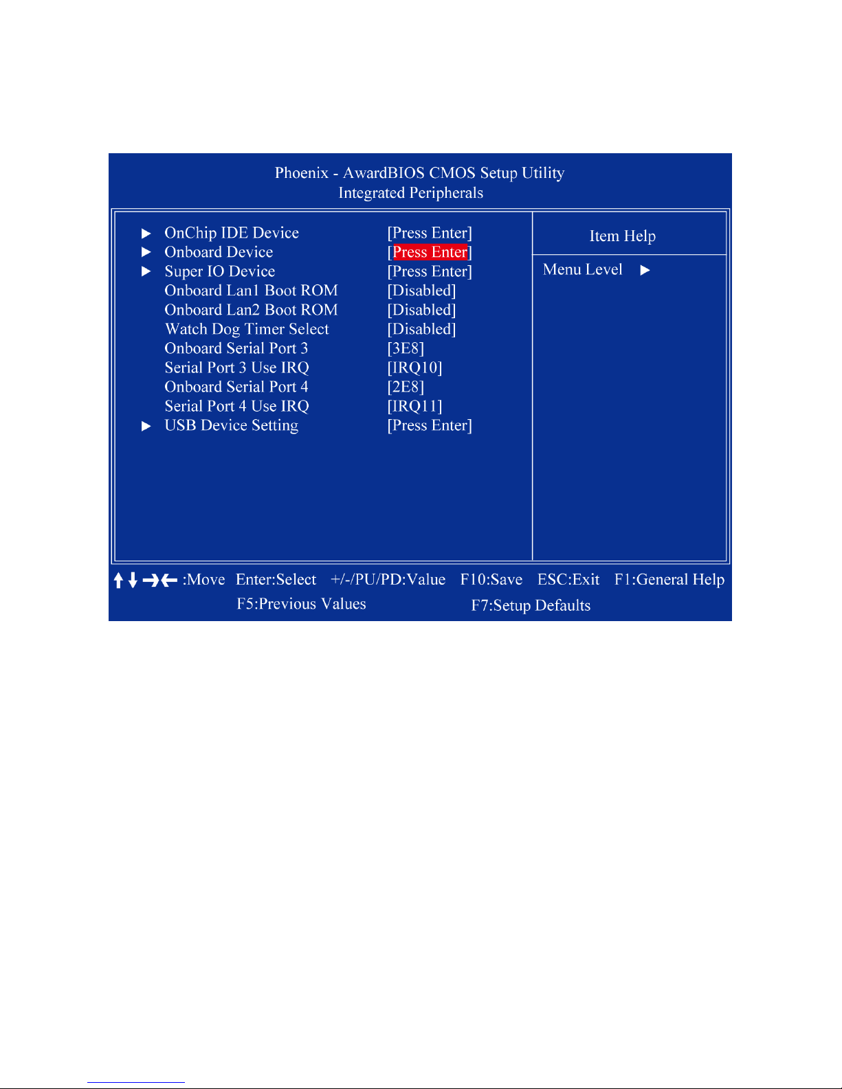
2.3.4 Integrated Peripherals
Page 48
MX945GSE3 User’s Manual
48
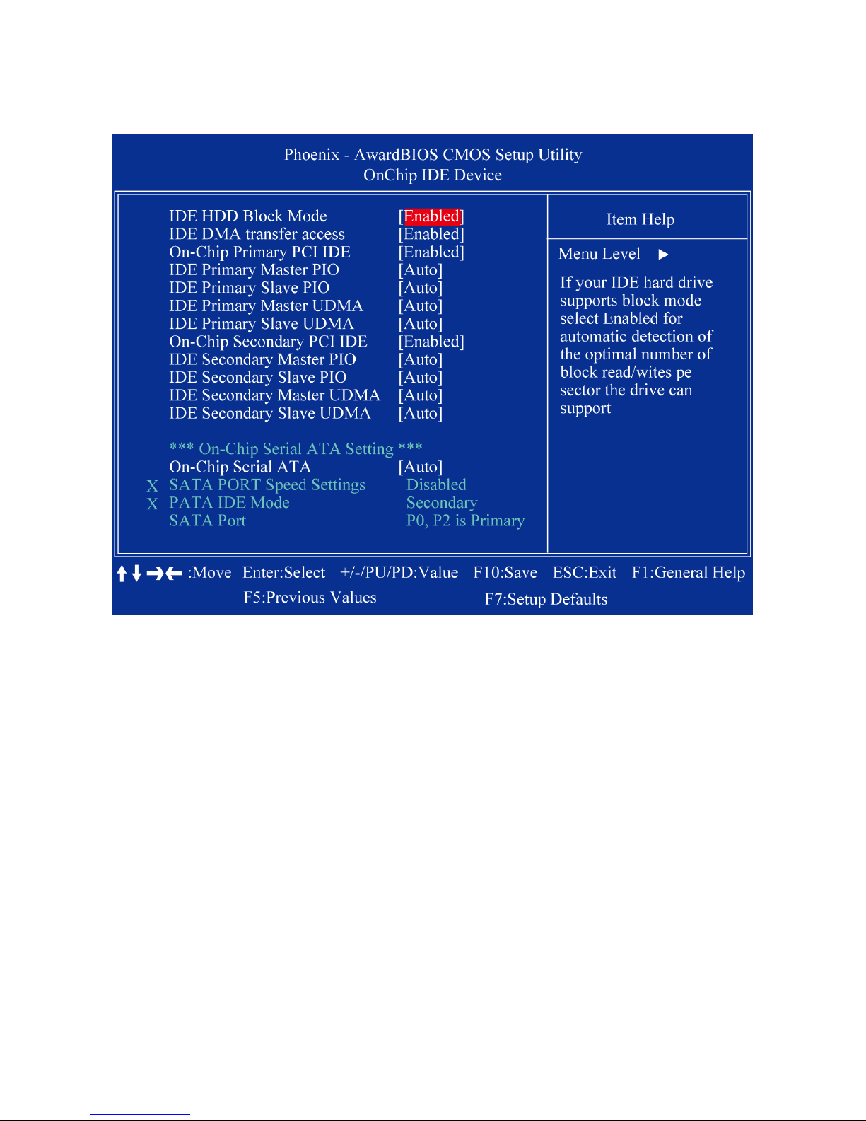
2.3.4.1 OnChip IDE Device
IDE HDD Block Mode
Block mode is also called block transfer, multiple commands, or multiple sector
read/write. If your IDE hard drive supports block mode (most new drives do), select
Enabled for automatic detection of the optimal number of block read/writes per sector
the drive can support
IDE DMA transfer access
To Enable/Disable the IDE DMA transfer access
OnChip Primary PCI IDE
The integrated peripheral controller contains an IDE interface with support for two IDE
channels. Select Enabled to activate each channel separately
IDE Primary/Secondary Master/ Slave PIO
The f our IDE PIO fields allow you to set a PIO mode (0-4) for each of the four IDE
devices that the onboard IDE interface supports. Modes 0 through 4 provide
successively increased performance. In Auto mode, the system automatically
determines the best mode for each device.
IDE Primary/Secondary Master/ Slave UDMA
Ultra DMA/33 implementation is possible onl y if y our IDE har d driv e support s it and the
Page 49
MX945GSE3 User’s Manual
49
operating environment includes a DMA driver (Windows 95 OSR2 or a third-party IDE
bus master driver). If you hard drive and your system software both support Ultra
DMA/33, select Auto to enable BIOS support
On-Chip Secondary PCI IDE
Enable the secondary IDE channel
On-Chip SATA Controller
To select Serial ATA mode. The choices are “Native IDE” / “RAID” / “AHCI” / “Legacy
IDE”.
SATA Port Speed Settings
PATA ID E Mode
SATA Por t
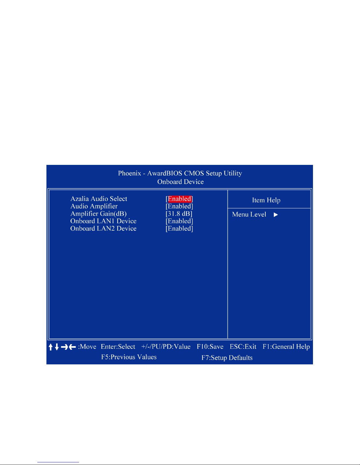
2.3.4.2 Onboard Device
Azalia Audio Select
Select [Disabled] if you do not want to use Azalia audio. Configuration options:
[Auto] [Disabled]
Audio Amplifier
Amplifier Gain(dB)
Onboard LAN1 Device
Page 50

MX945GSE3 User’s Manual
50
Onboard LAN2 Device
2.3.4.3 SuperIO Device
POWER ON Function
KB Power ON Password
The system will ask for a password, after entering the correct password the keyboard
can then be used.
Hot Key Power ON
Awaken the system by pr essing the hot key button. The ch oices ar e “C trl-F1”, “Ctrl-F2”,
“Ctrl-F3” to “Ctrl-F8”.
Onboard Serial Port 1/2
The settings are “3F8/IRQ4”, “2F8/IRQ3”, “3E8/IRQ4”, “2E8/IRQ3”, and “Disabled” for
the on-board serial connector.
PWRON After PWR-Fail
This item allows you to select if you want to power on the system after power failure.
The choice: Off, On, Former-Sts.
2.3.4.4 Onboard Lan1/2 Boot ROM
The choices: Enable, Disable.
Page 51
MX945GSE3 User’s Manual
51
2.3.4.5 Watch Dog Timer Select
This option will determine watch dog timer. The choices: Disabled, 10, 20, 30, 40 Sec. 1, 2,
4 Min.
2.3.4.6 Onboard Serial Port 3/4
The settings are “3F8/IRQ4”, “2F8/IRQ3”, “3E8/IRQ4”, “2E8/IRQ3”, and “Disabled” for the
on-board serial connector.
2.3.4.7 Serial Port 3/4 Use IRQ
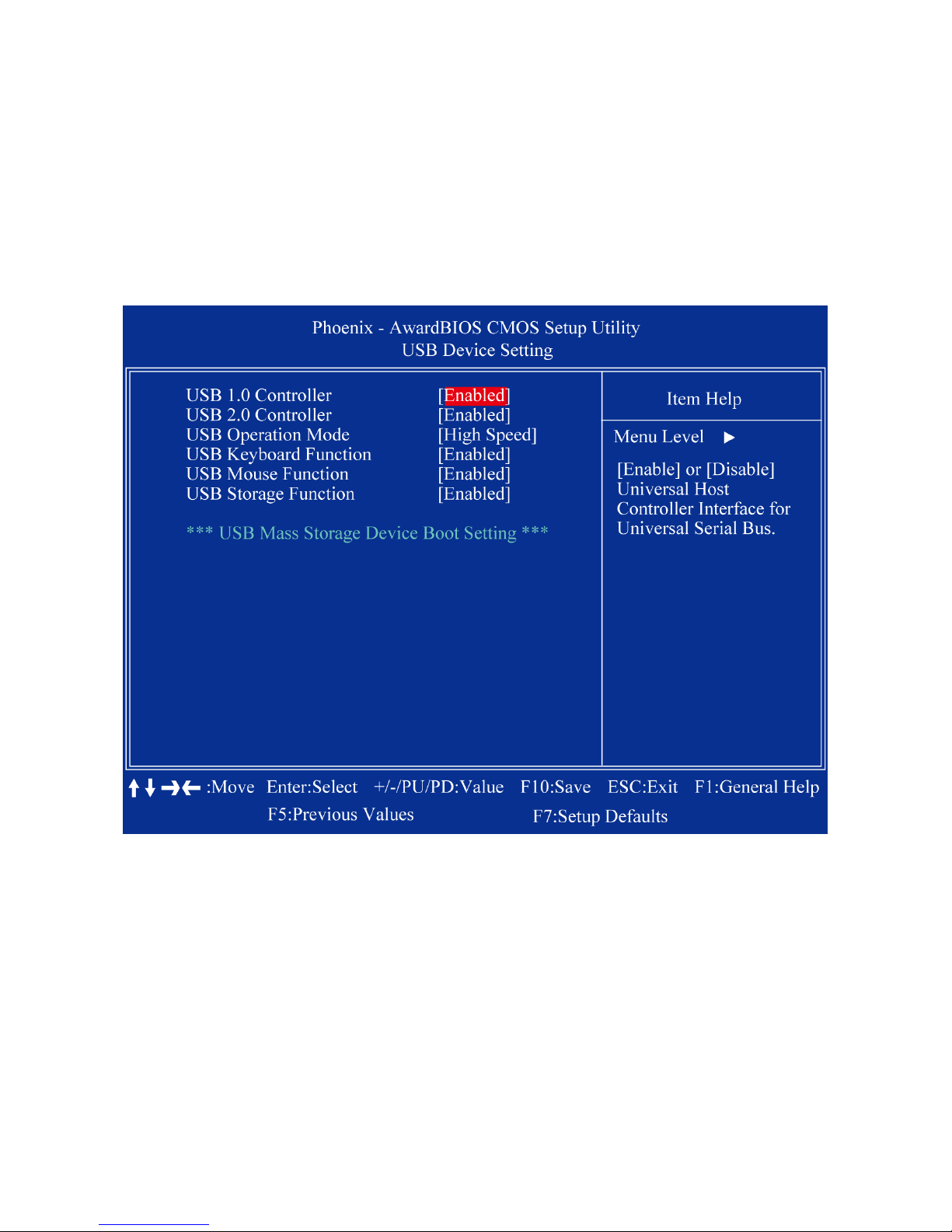
2.3.4.8 USB Device Setting
USB Controller
This should be enabled if your system has a USB installed on the system board and
you want to use it. Even when so equipped, if you add a higher performance co nt rol l er ,
you will need to disable this feature
USB 2.0 Controller
Enable the USB 2.0 controller
USB Keyboard Support
Select Enabled if your system contains a Universal Serial Bus (USB) controller and
you have a USB keyboard.
USB Mouse Support
Select an address and corresp on di ng interr upt for the first and second serial ports
Page 52
MX945GSE3 User’s Manual
52
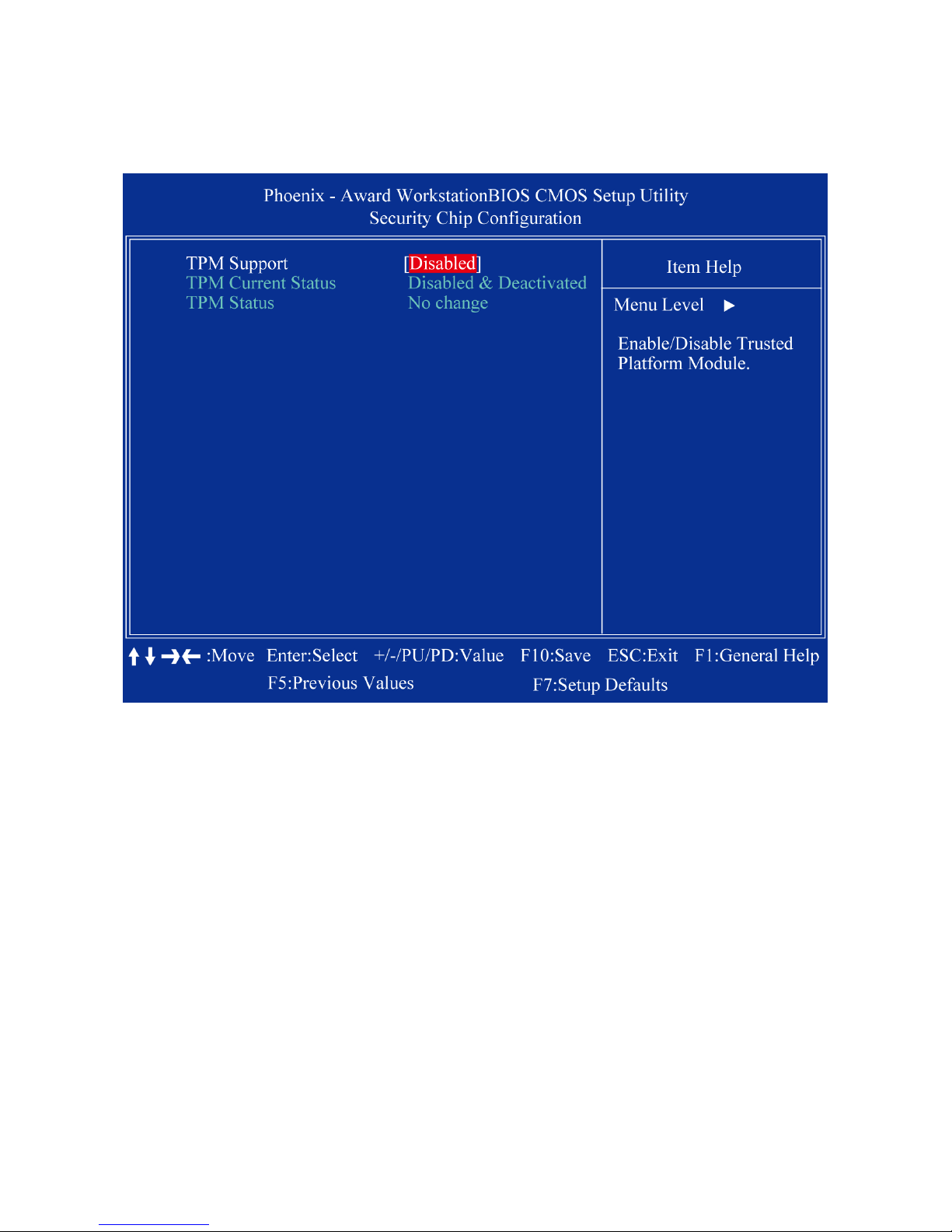
2.3.5 Security Chip Configurati on
2.3.5.1 TPM Support
The choices are “Enabled” and “Disabled”.
2.3.5.2 TPM Current Status
This item shows you the current TPM status.
2.3.5.3 TPM Status
The choices are “No Change” / “Clear” / “Enable & Activate” / “Deactivate & Disable”.
Page 53
MX945GSE3 User’s Manual
53
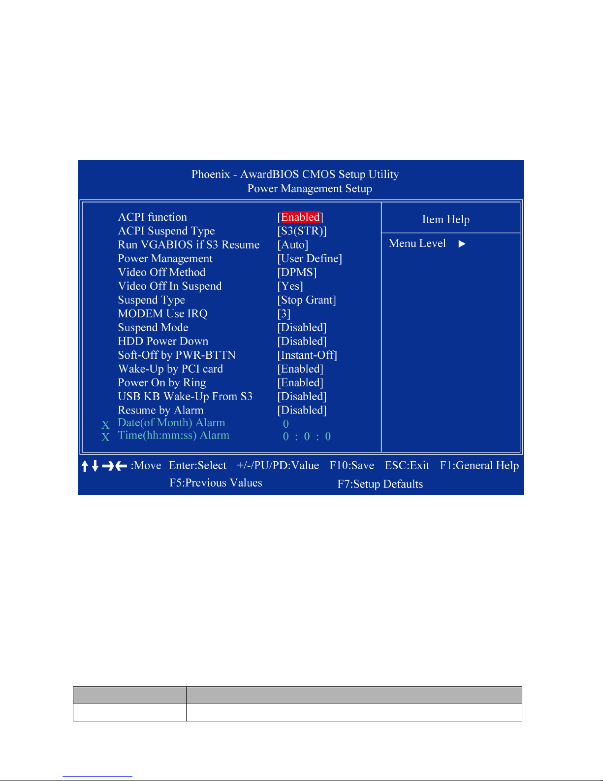
2.3.6 Power Management Setup
The power management setup controls the single board computer's “green” features to
save power. The following screen shows the manufacturer’s defaults.
2.3.6.1 ACPI Function
The choices are “Enabled” and “Disabled”.
2.3.6.2 ACPI Suspend Type
This item allows you to set ACPI suspend type to S1/POS(Power On Suspend) or
S3/STR(Suspend To RAM) .
2.3.5.4 Run VGABIOS if S3 Resume
Select “Auto” to run V GA BIO S i f S3 res ume automa tical ly . The “Y es” enables r unni ng VG A
BIOS if S3 resume. The “No” disables this function.
2.3.5.5 Power Management
There are three selections for Power Management, and each of them has fixed mode
settings.
Item Description
Min. Power Saving Minimum power management, HDD Power Down = 15 Min
Page 54

MX945GSE3 User’s Manual
54
Max. Power Saving Maximum power management, HDD Power Down =1 Min
User Defined
Allows you to set each mode i ndiv idual ly . When not disabl ed, each
of the ranges are from 1 min. to 1 hr. except for HDD Power Down
which ranges from 1 min. to 15 min. and disable.
2.3.5.6 Video Off Method
Use this to select the method to turn off the video. The choices are “Blank Screen” , “V/H
SYNC+ Blank”, and “DPMS”.
2.3.5.7 Video Off In Suspend
When the system is in suspend mode, the video will turn off. The choices are “No” and
“Yes”.
2.3.5.8 Suspend Mode
Item Description
Min. Power Saving Minimum power management, HDD Power Down = 15 Min
Max. Power Saving Maximum power management, HDD Power Down =1 Min
User Defined
Allows you to set each mode i ndiv idual ly . When not disabl ed, each
of the ranges are from 1 min. to 1 hr. except for HDD Power Down
which ranges from 1 min. to 15 min. and disable.
2.3.5.9 Soft-Off by PWR-BTTN
If you choose “ Insta nt-Off”, then pushing the ATX sof t power sw itch but- ton once will switch
the system to “system off” power mode. You can choose “Delay 4 sec”. If you do, then
pushing the button for more than 4 seconds will turn off the system, whereas pushing the
button momentarily (for less than 4 seconds) will switch the system to “suspend” mode.
2.3.5.10 Wake-up by PCI Card
The choices are “Enabled” and “Disabled”.
2.3.5.11 Power On by Ring
2.3.5.12 USB KB Wake-up From S3
2.3.6.3 Resume by Ala rm
When Enabled, your can set the date and time at which the RTC (real-time clock) alarm
awakens the system from Suspend mode.
Page 55
MX945GSE3 User’s Manual
55
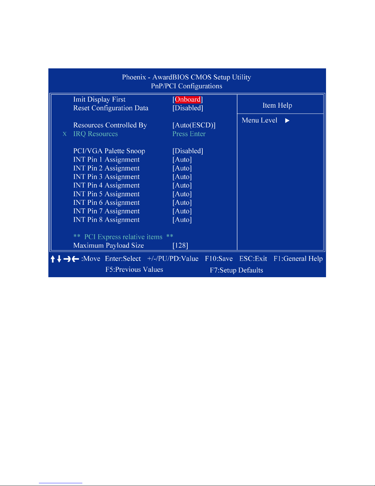
2.3.7 PnP/PCI Configurations
2.3.6.1 Imit Display First
2.3.6.2 Reset Configuration Data
The default is “Disabled”. Select Enabled to reset Extended System Configuration Data
(ESCD) if you have i nstal led a new add-on ca rd, and sy stem co n figu ration i s in s uch a stat e
that the OS cannot boot.
2.3.6.3 Resources Controlled By
The commands here are “Auto(ESCD)” or “Manual”. Choosing “Manual” requires you to
choose resources from the following sub-menu. “Auto(ESCD)” automatically configures all
of the boot and Plug and Play devices, but you must be using Windows 95 or above.
2.3.6.4 PCI/VGA Palette Snoop
This is set to “Disabled” by default.
2.3.6.5 Maximum Payload Size
This allows y ou to se t t he max imu m TLP p ayload siz e for PCI Ex press dev ices. The opti ons
are [128 bytes], [256 byt es], [512 byt es], [10 2 4 by tes] , [2048 bytes], and [4096 bytes].
Page 56
MX945GSE3 User’s Manual
56
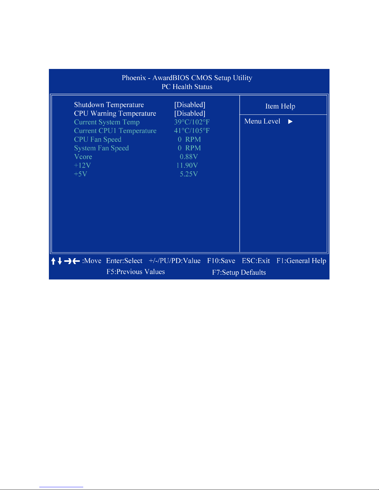
2.3.8 PC Health Status
2.3.8.1 Shutdown Temperature
2.3.8.2 CPU Warning Temperature
2.3.8.3 Current SYSTEM Temperature
This item shows you the current system temperature.
2.3.8.4 Current CPU1 Temperature
This item shows you the current CPU temperature.
2.3.8.5 CPU Fan Speed
This item shows you the current CPU fan speed.
2.3.8.6 System Fan Speed
This item shows you the current system fan speed.
2.3.8.7 Vcore
This item shows you the current Vcore voltage value.
2.3.8.8 +12V
This item shows you the current +12V voltage value.
2.3.8.9 +5V
This item shows you the current +5V voltage value.
Page 57
MX945GSE3 User’s Manual
57
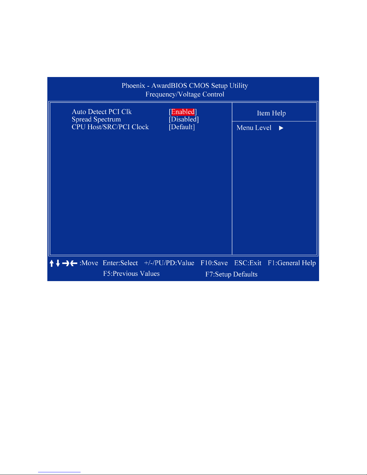
2.3.9 Frequency/Voltage Control
2.3.8.1 Auto Detect PCI Clk
This allows you to enable or disable auto detect PCI clock. The choices are “Enabled” and
“Disabled”.
2.3.8.2 Spread Spectrum
This setting allows you to reduce EMI by modulating the signals the CPU generates so that
the spikes are reduced to flatter curves. This is achieved by varying the frequency slightly
so that the signal does not use any particular frequency for more than a moment. The
choices are “Disabled” and “Enabled”.
2.3.8.3 CPU/Host/SRC/PCI Clock
The choice: 100
Page 58
MX945GSE3 User’s Manual
58
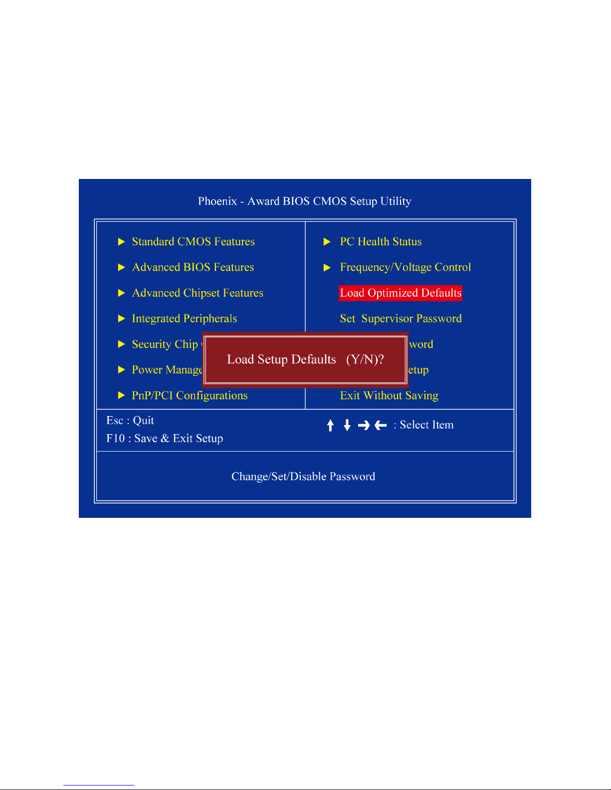
2.3.10 Load Optimized Defaults
Use this menu to load the BIOS default values for the minimal/stable performance for your
system to operate. Press <Y> to load the BIOS default values for the most stable,
minimal-performance system operations.
Page 59
MX945GSE3 User’s Manual
59
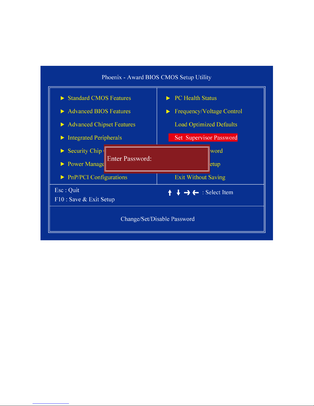
2.3.11 Set Supervisor Password
You can set password to be able to enter/change the options of setup menus.
Follow these steps to change the password.
Choose the “Set Password” option from the “Initial Setup Screen” menu and press
<Enter>. The screen displays the following message:
Please Enter Your Password
Press <Enter>.
If the CMOS is good and this option has been used to change the default password,
the user is asked for the password stored in the CMOS. The screen displays the
following message:
Please Confirm Your Password
Type the current password and press <Enter>.
After pressing <Enter> (ROM password) or the current password (user-defined), you
can change the password stored in the CMOS. The password must be no longer than
eight (8) characters. Remember, to enable the password setting feature, you must first
select either “Setup” or “System” from the “Advanced BIOS Features” menu.
Page 60
MX945GSE3 User’s Manual
60
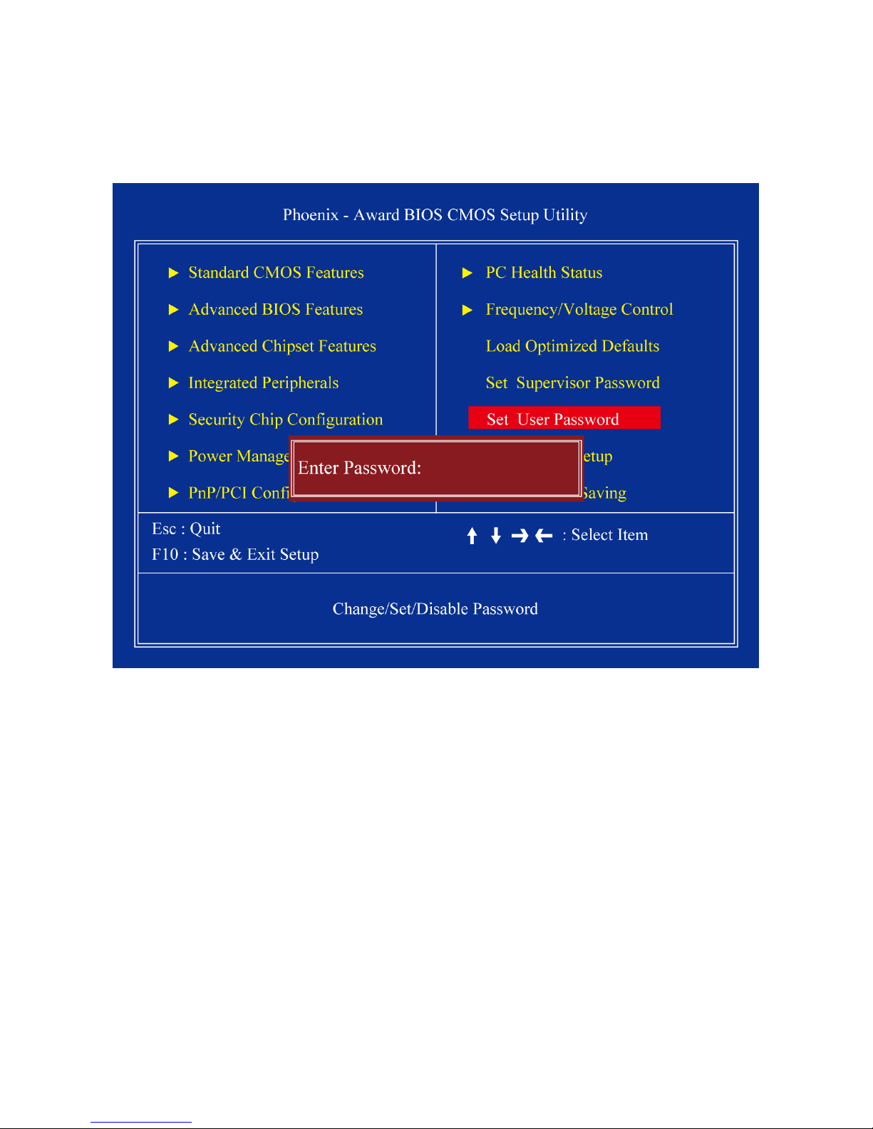
2.3.12 Set User Password
You can set password to be able to enter/change the options of setup menus.
Follow these steps to change the password.
Choose the “Set Password” option from the “Initial Setup Screen” menu and press
<Enter>. The screen displays the following message:
Please Enter Your Password
Press <Enter>.
If the CMOS is good and this option has been used to change the default password,
the user is asked for the password stored in the CMOS. The scre en disp l ay s the
following message:
Please Confirm Your Password
Type the current password and press <Enter>.
After pressing <Enter> (ROM password) or the current password (user-defined), you
can change the password stored in the CMOS. The password must be no longer than
eight (8) characters. Remember, to enable the password setting feature, you must first
select either “Setup” or “System” from the “Advanced BIOS Features” menu.
Page 61
MX945GSE3 User’s Manual
61
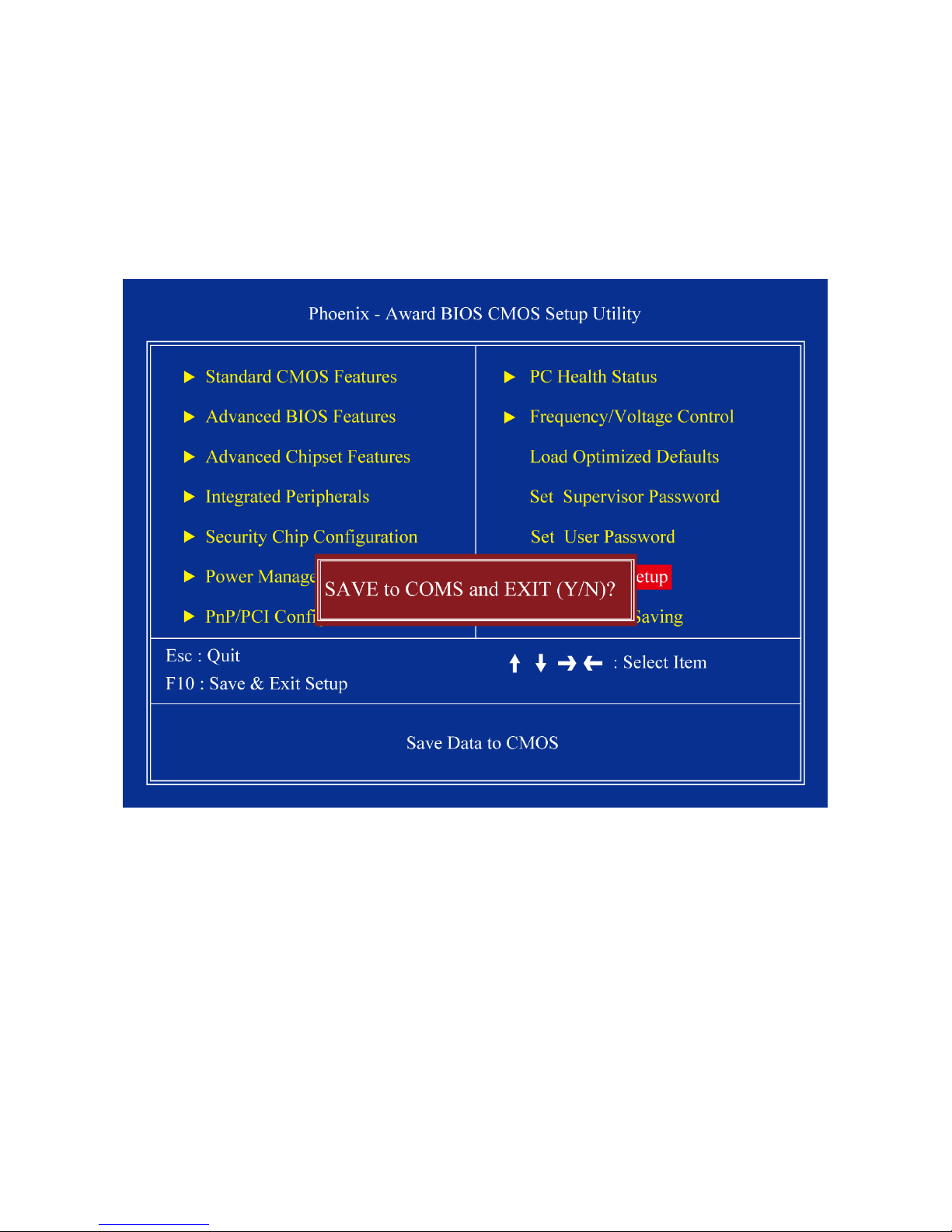
2.3.13 Save & Exit Setup
If you select this and press <Enter>, the values entered in the setup utili- ties will be
recorded in the CMOS memory of the chipset. The processor will check this every time you
turn your system on and co mpar e thi s t o w hat it finds as i t checks the system. This recor d i s
required for the sys- tem to operate.
Page 62

MX945GSE3 User’s Manual
62
2.3.14 Exit Without Saving
Selecting this option and pressing <Enter> lets you exit the setup program without
recording any new values or changing old ones.
 Loading...