

Page 1
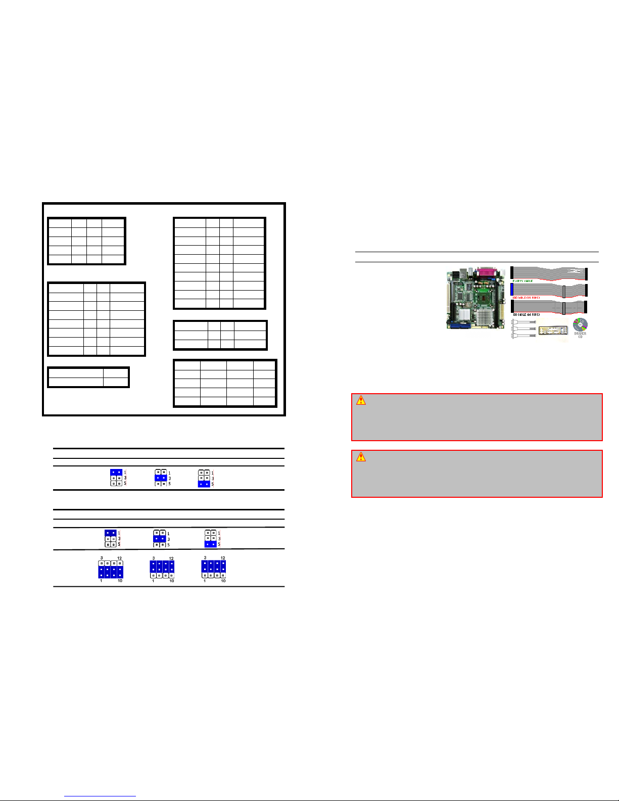
COM Ports Settings
COM1 Pin9 Signal Select (JP1)
MX855E COM1 pin 9 signal can be selected as +12V, +5V, or Ring by setting JP1.
COM1 Select (JP1)
RI* +5V +12V
COM1 RS232/422/485 Select (JP2, JP3)
MX855E COM1 serial port can be selected as RS-232, RS-422, or RS-485 by setting JP2, JP3.
COM1 Select (JP2, JP3)
RS232* RS422 RS485
Serial Port Header JCOM1, JCOM2, JCOM3
Front Panel Connector JFP1
Clear CMOS JBAT1
RESET 1 2 SYS_LED+
GND 3 4 SYS_LED-
HDD_LED+ 5 6 PWR_LED+
HDD_LED- 7 8 PWR_LED-
VCCSB 9 10 SUS_LED+
PWR_BTN 11 12 SUS_LED-
SUS-BTN 13 14 PC_SPK+
GND 15 16 PC_SPK-
DCD 1 2 RxD
TxD 3 4 DTR
GND 5 6 DSR
RTS 7 8 CTS
RI 9 10 NC
Protect (Default) 1-2
Clear CMOS 2-3
ATX Power Connector Block
TV Out Connector JTV1
USB Connector JUSB1, JUSB2
+5V 1 2 GND
-D 3 4 GND
+D 5 6 D+
GND 7 8 DGND 9 10 +5V
3.3V 11 1 3.3V
-12V 12 2 3.3V
GND 13 3 GND
PS-ON 14 4 +5V
GND 15 5 GND
GND 16 6 +5V
GND 17 7 GND
+5V 18 8 PWROK
+5V 19 9 5VSB
+5V 20 10 +12V
Pb 1 2 GND
PR 3 4 Y
GND 5 6 GND
JP2
JP3
MX852E
MX852E-C1G
Mini ITX with Intel Celeron M 1GHz Processors
4 COM Port, 6USB 2.0 10/100/1000 LAN, 1xPCI, 1xMini PCI
and 18/36bit LVDS DFP Support
User’s Quick Start Card
Version 1.00
http://www.bcmcom.com
Inspect the Package:
One MX852E-C1G Motherboard
One IDE Cable (40Pin 80 Wires)
One IDE Cable (44Pin 44 Wires)
One Floppy Cable
Three COM port Cable (DB9)
One Standard ATX I/O Shield
0One User’s Quick Start Card
One Driver CD (Manual/Drivers)
One CPU Heatsink
Responsibility:
This manual is provided “As-Is” with no warranties of any kind, it will neither expressed or
implied, including, but not limited to the implied warranties or conditions of this product’s fitness
for any particular purpose. In no event shall we be liable for any loss of profits, loss of business,
loss of data, interruption of business, or indirect, special, incidental, or consequential damages
of any kind, even the possibility of such damages arising from any defect or error in this manual
or product. We reserve the right to modify and update the user manual without prior notice.
WARNING: CMOS Battery Damage
Replace your system’s CMOS RAM battery only with the identical CR-2032 3V Lithium-Ion coin
cell (or equivalent) battery type to avoid risk of personal injury or physical damage to your
equipment. Always dispose of used batteries according to the manufacturer’s instructions, or
as required by the local ordinance (where applicable). The damage due to not following this
warning will void your motherboard’s manufacturer warranty.
ATTENTION: Incorrect BIOS Setup
If you do not know how to handle BIOS setup or how to set it up properly, it is strongly
advisable that you do not modify any of the settings than otherwise instructed in the User’s
Quick Start Card. Even a seemingly small incorrect adjustment or modification in the BIOS
setup can render your system unstable or unusable. The incorrect BIOS setup is not covered
by your motherboard’s manufacturer warranty.
Additional Information:
Additional information on setting this board up can be found in the User’s Manual in the
provided CD-ROM. The Online User’s Manual and FAQ/Knowledge Base can be found on our
website by visiting our website: http://www.bcmcom.com. If your question is not answered in
our FAQ/Knowledge Base, visit our forums and post your messages or submit a new FAQ
through FAQ Submittal form for us to add your question in our FAQ with our answer.
Page 2
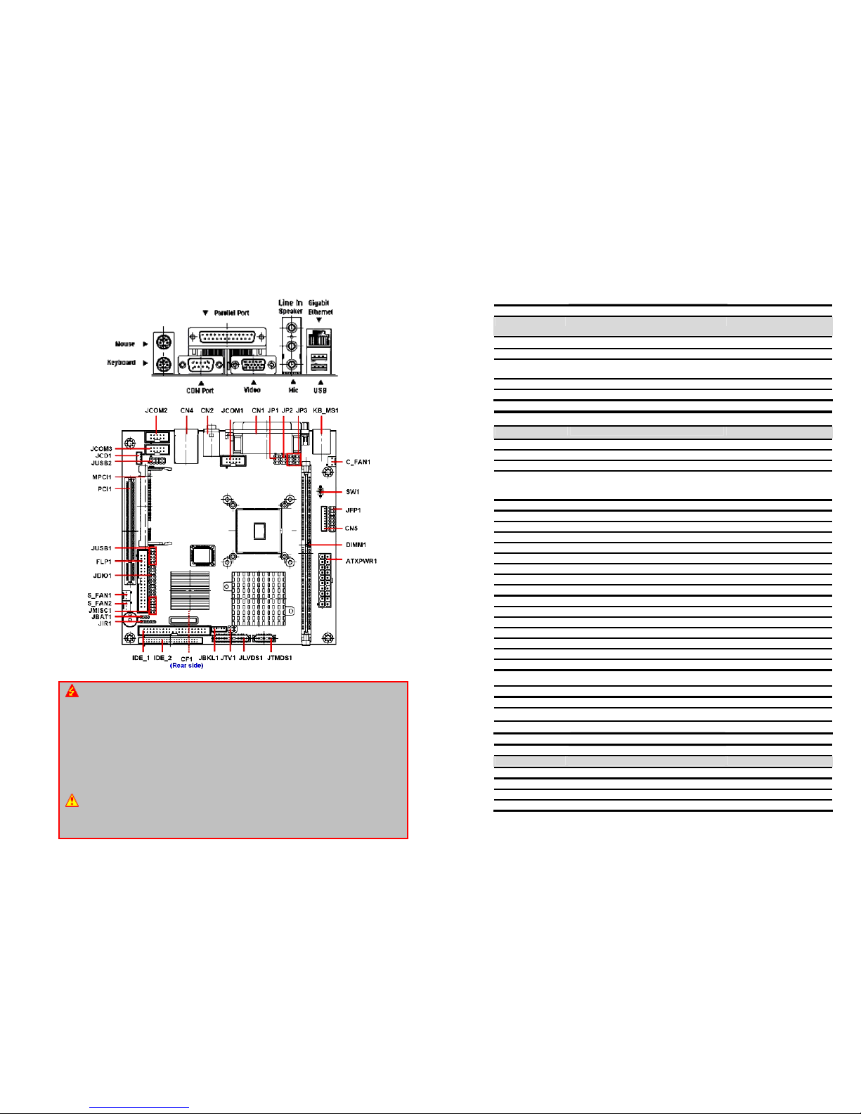
Motherboard Layout:
WARNING: Electrostatic Sensitive Device (ESD)
Static electricity can easily damage your motherboard and will void your motherboard warranty.
Keep the motherboard and other system components in their anti-static packaging until you are
ready to install them. Touch a grounded surface before you remove any system component
from its protective anti-static packaging. Unpacking and installation should be done on a
grounded, anti-static mat. The operator should be wearing an anti-static wristband, grounded
at the same points as the anti-static mat. During configuration and installation touch a
grounded surface frequently to discharge any static electrical charge that may have built up in
your body. Avoid touching the components when handling the motherboard or a peripheral
card. Handle the motherboard and peripheral cards either by the edges or by the peripheral
card case-mounting bracket.
WARNING: Misplaced Jumper Damage
Incorrect setting jumpers and connectors may lead to damage to your motherboard and will
void your motherboard warranty. Please pay special attention not to connect these headers in
wrong directions. DO NOT change ANY jumpers while the motherboard has the power!
The following tables list the function of each of the board's jumpers and connectors.
Jumpers
Label Function Note
JBAT1
Clear CMOS 3 x 1 header, pitch 2.54mm
JP1
COM1 pin 9 signal select 3 x 2 header, pitch 2.0mm
JP2, JP3
COM1 RS-232/422/485 select 3 x 2 header, pitch 2.0mm
4 x 3 header, pitch 2.0mm
SW1
4/5/8-wire touch screen select Switch
SW2
Reserved Switch
Connectors
Label Function Note
ATXPWR1
ATX Power connector ATX power connector
C_FAN1
CPU fan connector 3 x 1 wafer, pitch 2.54mm
CF1
CF card connector
CN1
Parallel port connector
Serial port 1 connector
VGA connector
D-sub 25-pin, female
D-sub 9-pin, male
D-sub 15-pin, female
CN2
Audio connector Phone Jack X 3
CN4
RJ-45 Ethernet / USB 0 & 1 connector
CN5
4/5/8-wire touch screen connector 9 x 1 wafer, pitch 2.0mm
DIMM1
184-pin DDR SDRAM DIMM socket
FLP1
Floppy connector 17 x 2 header, pitch 2.54mm
IDE_1
Primary IDE connector 20 x 2 header, pitch 2.54mm
IDE_2
Secondary IDE connector 22 x 2 header, pitch 2.0mm
JBKL1
LCD inverter connector 5 x 1 wafer, pitch 2.0mm
JCD1
CD-ROM audio input connector 4 x 1 wafer, pitch 2.0mm
JCOM1
Serial port 2 connector 5 x 2 header, pitch 2.54mm
JCOM2
Serial port 3 connector 5 x 2 header, pitch 2.54mm
JCOM3
Serial port 4 connector 5 x 2 header, pitch 2.54mm
JDIO1
Digital input/output connector 10 x 2 header, pitch 2.54mm
JFP1
Front panel connector 8 x 2 header, pitch 2.54mm
JIR1
IrDA connector 5 x 1 header, pitch 2.54mm
JLVDS1
LVDS connector HIROSE DF13-40DP-1.25V
JMISC1
Miscellaneous setting connector 5 x 2 header, pitch 2.54mm
JTMDS1
TMDS connector HIROSE DF13-20DP-1.25V
JTV1
TV out connector 3 x 2 header, pitch 2.54mm
JUSB1
USB connector 2 & 3 5 x 2 header, pitch 2.54mm
JUSB2
USB connector 4 & 5 5 x 2 header, pitch 2.54mm
Connectors
Label Function Note
KB_MS1
PS/2 Keyboard & mouse connector 6-pin Mini-DIN x 2
MPCI1
Mini PCI slot
PCI1
PCI slot
S_FAN1,S_FAN2
System fan connector 1 & 2 3 x 1 wafer, pitch 2.54mm
 Loading...