


Micronics C300
Pentium II
System Board Manual
Document Number: 06-00350-01, Rev. B03
August 1998
2880 Junction Avenue, San Jose, CA. 95134-19228

Copyright Notices
Copyright 1998 Diamond Multimedia Systems Inc. The information
contained in the Micronics C300 PCI/ISA/AGP Pentium II system
2
board manual has been carefully checked and is believed to be accurate.
Diamond assumes no responsibility for any inaccuracies that may be
contained in this document. Diamond makes no commitments to
update or to keep the information in this manual at a current level when
changes are made to the product.
Diamond reserves the right to make changes to this document and/or
product at any time and without notice. All Rights Reserved. No part of
this document may be photocopied, reproduced, translated, or reduced
to any medium or machine form without prior, written consent from
Diamond Multimedia Systems Inc.
Portions of the Manual
Portions of this manual were copied (with permission) from American
Megatrends, Inc.. All rights reserved.
Trademarks
IBM is a registered trademark of International Business Machines.
Microsoft and Windows are registered trademarks of Microsoft Corporation. Intel, PCI and AGP are registered trademarks of Intel
Corporation. All other product names mentioned herein are used for
identification purposes only and may be the trademarks of their
respective companies.
Micronics C300 System Board Manual

Table of Contents
Introduction 5
Features 6
Software Compatibility 7
Contents Listing 7
Before You Begin 8
Chapter 1 - Quick Installation 9
Installing the Micronics C300 9
Chapter 2 - Configuring the Micronics C300 11
Static Electricity 11
Environment Considerations 11
Micronics C300 System Board 12
Back Panel Connections 12
Connector and Jumper Settings 13
Chapter 3 - Installing the Micronics C300 15
Introduction 15
System Memory Support 15
Installing the Micronics C300 16
Tools Required 16
Equipment Required 16
System Memory 17
Adding Memory 17
Memory Configurations 18
Installing DIMMs 20
Removing DIMMs 20
CPU Installation 21
Installing the CPU Retention Mechanism 21
Installing a CPU 22
Micronics C300 System Board Manual
1

CPU Installation Overview 24
CPU Installation (Box version) 25
Installing a PCI Peripheral Card 26
Installing an ISA Peripheral Card 27
Installing an AGP Peripheral Card 28
Chapter 4 - The BIOS Setup Utility 29
Configuration 29
Initial Bootup 29
Setup 29
Running the Setup Procedure 31
Standard CMOS Setup 32
Advanced CMOS Setup 34
Advanced Chipset Setup 37
Power Management Setup 40
PCI/Plug and Play Setup 44
Peripheral Setup 47
CPU Speed Setup 49
Auto Detect Hard Disks 50
Change Supervisor Password 50
Auto Configuration w/ Optimal Settings 50
Auto Configuration w/ Fail Safe Settings 50
Exiting the Main Menu 51
Chapter 5 - Special Features 53
Accelerated Graphics Port (AGP) 53
Wake On LAN 53
Ultra DMA/33 IDE 54
Universal Serial Bus (USB) 54
2
Micronics C300 System Board Manual

Appendix A - Technical Information 55
Specifications 55
Environmental Specifications 57
Temperature Range 57
Relative Humidity 57
Battery Disposal 58
Support and Information Services 59
Technical Support 59
Appendix B - Post Messages 61
Appendix C - Updating the System BIOS 67
Appendix D - Warranties and Notices 69
Limited Warranty 69
Non-Warranty Service 70
FCC Statement 71
Glossary 72
Index 76
Micronics C300 System Board Manual
3

List of Figures
Figure 1.1: Power-Up Screen 10
Figure 2.1: Micronics C300 System Board 12
Figure 2.2: Back Panel Connections 12
Figure 3.1: Installing a 168-Pin DIMM 20
Figure 3.2: Installing a CPU 24
Figure 3.3: Installing a CPU (Boxed version) 25
Figure 3.4: Installing a PCI Card 26
Figure 3.5: Installing an ISA Peripheral Card 27
Figure 3.6: Installing an AGP Peripheral Card 28
Figure 4.1: Power-Up Screen 30
Figure 4.2: AMI BIOS Setup Utility Main Screen 31
Figure 4.3: Standard CMOS Screen 32
Figure 4.4: Advanced CMOS Setup Screen 34
Figure 4.5: Advanced Chipset Setup Screen 37
Figure 4.6: Power Management Setup Screen 40
Figure 4.7: PCI/Plug and Play Setup 44
Figure 4.8: Peripheral Setup Screen 47
Figure 4.9: CPU Speed Setup Screen 49
List of Tables
Table 2.1: Connector Settings and Functions 13
Table 2.2: Wake On LAN Select 14
Table 3.1: Memory Configurations 18
Table A.1: Support and Information Services 60
4
Micronics C300 System Board Manual

Introduction
Introduction
Thank you for choosing the Micronics C300 system board.
The Micronics C300 is an advanced single processor solution for the industry’s most demanding workstation and
server applications.
Based on the Intel 440LX AGPset, the Micronics C300
supports the latest advanced processor architecture, the
Pentium II (processor-on-a-cartridge), which provides
the speed and performance necessary to address the most
intensive computational applications. Hardware management support, Ultra DMA/33 IDE hard drive protocol (up
to 33MBytes/sec transfer rate), Wake On LAN and
SDRAM memory support make this board powerful and
feature rich.
In addition, the Micronics C300 comes with an AGP
(Accelerated Graphics Port) bus slot, a faster bus than the
current 33MHz PCI bus. The AGP bus provides a direct
connection between the graphics subsystem and system
memory.
All products are built to exacting standards, using the
highest quality components available. We are proud to
provide this system board and believe you will be pleased
with your purchase.
Micronics C300 System Board Manual
5

Introduction
Features
The Micronics C300 includes the following features:
▲ Single Intel Slot 1
Intel Pentium II 233-333MHz
Intel Celeron 233-333MHz
Integrated 512KB second-level cache
▲ Intel 440LX AGPset
Intel PIIX4
▲ Jumperless CPU configuration
▲ One AGP slot
Four 32-bit PCI slots
One shared PCI/ISA slot
One 16-bit ISA slot
▲ Three 3.3V unbuffered 64/72-bit 168-pin DIMM sockets
Maximum memory 384MB of SDRAM or EDO DRAM
ECC support via chipset
▲ Hardware Management - microprocessor system hard-
ware monitor w/ CPU and chassis fan temperature sensors
▲ Ultra DMA/33 IDE support
▲ Mini ATX form factor
support for:
6
Micronics C300 System Board Manual

Introduction
Software Compatibility
The Micronics C300 system board has been thoroughly tested
for compatibility with a variety of operating systems and
environments, including:
▲ Microsoft -
DOS 6.2x
Windows 95
Windows 98
Windows NT 3.5x
Windows NT 4.0
▲ IBM -
OS/2 Warp 4.0
▲ SCO -
UNIXWare 2.1.1
Open Server 5.04
▲ Novell -
NetWare 3.12
NetWare 4.11 (IntranetWare)
Contents Listing
The standard package should contain the following items.
Check to make sure that all the items are included.
▲ Micronics C300 System Board
▲ Micronics C300 CD (includes this manual in Adobe
Acrobat format)
▲ Two device 34-pin floppy disk drive ribbon cable
▲ Two device 40-pin hard disk drive ribbon cable
▲ Pentium II CPU retention post set
Micronics C300 System Board Manual
7

Introduction
This manual will familiarize you with the features, installation
and use of your Micronics C300. There are several symbols and
conventions used throughout this manual to help draw your
attention to a feature or to focus on important information:
Common Names
Before You Begin
When you see the Magnifying Glass, it refers
to something you should take a closer look at
before proceeding further.
When you see the Exclamation Mark, it gives
important information on avoiding damage.
AGP Accelerated Graphics Port
DIMM Dual Inline Memory Module
DRAM Dynamic Random Access Memory
ECC Error Checking and Correction
EDO Extended Data Out
IDE Integrated Drive Electronics
PCI Peripheral Component Interconnect
SDRAM Synchronous DRAM
USB Universal Serial Bus
8
Micronics C300 System Board Manual

Chapter
1
Chapter 1: Quick Installation
Quick Installation
We know that many experienced people prefer to read as
little of the documentation as possible. If this sounds like
you, here’s the short form to get up and running quickly.
Installing the Micronics C300
1. Make backup copies of your installation and configuration diskettes.
STATIC!
Before
handling the
Micronics
C300, be
properly
grounded by
using a
special wrist
or ankle
strap, or
touch a
safely
grounded
object.
2. Ground yourself to prevent damaging static discharge by using an anti-static wrist or ankle strap, or
touch a safely grounded metal object.
3. Remove the Micronics C300 from its packaging.
4. Configure and verify the system board’s jumper settings (refer to Jumper Settings in Chapter 2).
5. Install the CPU and the system memory. Be sure to
attach the Retention Mechanism as described in
Chapter 3.
6. Install the system board in the chassis and make all
necessary case connections.
7. Install any ISA, PCI and/or AGP add-on peripherals
(refer to Chapter 2 for the location of the slots).
8. Connect any optional devices.
9. Turn the computer on and press the <DEL> key
when you see the screen shown in Figure 1.1.
Micronics C300 System Board Manual
9

Chapter 1: Quick Installation
Figure 1.1: Power-Up Screen
10. From the main menu highlight Standard CMOS Setup
and press ENTER. Set the time and date. Adjust the
BIOS settings to match your configuration. If installing
an IDE drive, select the IDE device you wish to configure. Press ENTER with Type selected and the BIOS will
automatically configure the drive for you (refer to Chapter 4).
11. From the main menu highlight CPU Speed Setup. Select
the speed for the CPU installed in your system.
12. Make any other desired setting configurations (refer to
Chapter 4). When finished, press F10 (Save and Exit) to
save your settings. When finished, go to the exit screen,
select “Save Settings and Exit” and you are finished with
the BIOS configuration (see Chapter 4).
10
Micronics C300 System Board Manual

Chapter 2: Configuring the Micronics C300
Chapter
2
Configuring the Micronics C300
Although the Micronics C300 system board is packaged in
materials that are designed to protect it from physical
damage and static electricity, it is important to use care
while unpacking the board and setting it up.
Static Electricity
The Micronics C300 is shipped from the factory in an antistatic bag. To reduce the possibility of damage from static
discharge, it is important to neutralize any static charges
your body may have accumulated before handling the
board.
The best way to do this is to ground yourself using a
special anti-static wrist or ankle strap. If you do not have
an anti-static strap available, touch both of your hands
to a safely grounded object, such as the power supply or
chassis of a computer that is connected to the power
socket. After you have grounded yourself, ground the
Micronics C300 board via one of the solder pads that
surround its mounting holes. When you remove the
Micronics C300 from its packaging, place it on top of the
anti-static bag, and carefully inspect the board for damage
which might have occurred during shipment.
Environment Considerations
Make sure the finished computer system is in an area with
good ventilation. The system should not be in direct
sunlight, near heaters, or exposed to moisture, dust, or
dirt.
Micronics C300 System Board Manual
11

Chapter 2: Configuring the Micronics C300
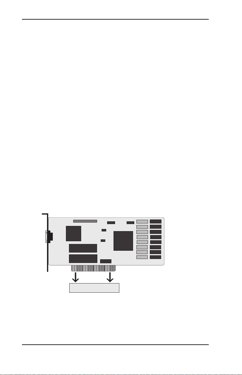
Micronics C300 System Board
Figure 2-1: Micronics C300 System Board Diagram
Back Panel Connections
Parallel Port (Printer)
COM 1
12
PS/2
Mouse
PS/2
Keyboard
USB 2
USB 1
Figure 2-2: Back Panel Connections
(Intel Venus I/O Shield Compatible)
Micronics C300 System Board Manual
COM 2

Chapter 2: Configuring the Micronics C300
Connector and Jumper Settings
This section provides connector settings for the Micronics C300 system
board that may or may not need to be changed. Other configurations can
be changed through the BIOS Setup, including the CPU speed. NOTE:
For details on how to configure the CPU speed, see “CPU Speed Setup” in
Chapter 4.
Table 2-1 lists the connector settings and their functions.
rotcennoCnoitcnuFsetoN
3-1MMIDMMIDnip-861(MARD
)stekcoS
2-1ASIstolSnoisnapxEsuBASI
1JrotcennoCdraobyeK2/SP
rotcennoCesuoM2/SP
3J,2JstroPlaireS2MOC&1MOC
4JrotcennoCBSU1troPBSU:leveLrewoL
5JrotcennoCtroPlellaraPleveLreppU
01J-6JstolSnoisnapxEsuBICP
11JrotcennoCNALnOekaW-2;tuptuOrewoPybdnatSV5+-1
21JtolSnoisnapxEsuBPGArotcennocnip-2x26
31JnaFgnilooC)1U(UPC
rotcennoC
81J,41JEDIyradnoceSdnayramirP
srotcennoCtroP
51JrotcennoCrewoPXTAnip-02
61JnaFgnilooCsissahC;rewoPV21+-2;dnuorG-1
MARDSdnaODEdereffubnu,tlov3.3
sMMID
leveLrewoL
leveLreppU
2troPBSU:leveLreppU
tupnIlangiSpuekaWNAL-3;dnuorG
;rewoPV21+-2;dnuorG-1
rotinoMdeepSnaF-3
secivedEDIowtotputroppushtoB
dnuorG-3
71JDELrewoPdnakcolyeK;dnuorG-2;kcolyeK-1
91JrotcennoCevirDyppolFsevirdyppolfowtotpustroppuS
T able 2-1: Connector Settings and Functions
Micronics C300 System Board Manual
-DEL-5;A/N-4;+DEL-3
13

Chapter 2: Configuring the Micronics C300
rotcennoCnoitcnuFsetoN
62J-02JrotcennoCO/IlenaPtnorF
"rekaepSCPlanretxEdraobnO;)nruterlangis(CDV5+-02J
"hctiwSteseRmetsySteseR;dnuorG-12J
"DELnO-rewoP-DEL;+DEL-22J
"DELDDH+DEL;-DEL;+DEL-32J
")RI(derarfnIroetomeRRI;timsnarTXT-RI-42J
"peelSDIL;dnuorG-52J
"ffO/nOrewoPmetsySdnuorG;nOrewoP-62J
72JlanretnI.rotcennoCkniL-BS
stroppustahtredaehoidua
retsalBdnuoSycageleht
ICPehtotoiduaelbitapmoc
.suB
1UUPCIImuitnePyramirP
dnuorGcigoL;langiSrekaepSCP
ccV;evieceRXR-RI;dnuorG;RItsaF
-3;dnuorG-2;tnarGAMDICP/CP-1
;tseuqeRAMDICP/CP-4;tcennoCoN
s'QRIlaireSICP-6;dnuorG-5
T able 2-1a: Connector Settings and Functions
Table 2-2 lists the settings to select Wake On LAN for high activity or low
activity.
14
repmuJnoitcnuFsgnitteS
3PJ)tluafed(nI-iH
nI-woL
T able 2-2: Wak e On LAN Select
3-2
2-1
Micronics C300 System Board Manual
PCI-PM#
Select
PCI-PM
[JP2]

Chapter 3: Installing the Micronics C300
Chapter
3
Installing the Micronics C300
Introduction
This chapter explains how to install the Micronics C300
system board, memory, CPU and peripherals.
WARNING: Before installing or removing any peripherals or
components, make sure you have a clear work space and that
you adhere to all anti-static precautions described in Chapter
1. Diamond recommends that only trained technicians install
and configure the system board.
Damage which occurs to the board while adding or removing
peripherals or components may void the warranty. If problems arise while installing peripherals, contact the computer
dealer where you purchased the peripheral or Diamond’s Technical Support Department.
System Memory Support
The flexibility of the Micronics C300 is augmented by its
support for EDO and SDRAM memory. The Micronics
C300 supports ECC (with 72-bit DIMMs) via the chipset.
SDRAM speed and synchronous operation have enabled
the breakthrough in memory-systems design needed to
meet the demands of fast high-performance processors.
SDRAM improves bandwidth to main memory because
all address, data and control signals are synchronized with
a system clock. With all operations in synch, system wait
states are eliminated, thus providing increased performance over conventional DRAM.
Micronics C300 System Board Manual
15

Chapter 3: Installing the Micronics C300
Installing the Micronics C300
Installation of the Micronics C300 system board depends on
the type of case you use. The Micronics C300 is designed for
the mini ATX form factor and must be installed in an ATX
chassis.
NOTE: If you are unfamiliar with installing a system board,
Diamond highly recommends that you read the computer user’s
manual or contact your dealer’s technical support department.
Tools Required
Diamond recommends using the following tools to install the
Micronics C300:
❏ Small Phillips screwdriver
❏ Tweezers or a pair of needle-nose pliers
❏ Tray (to hold loose screws)
Equipment Required
Diamond recommends using the following equipment with
the Micronics C300 for a typical configuration:
❏ ATX chassis with standard hardware.
❏ A high-quality ATX power supply capable of providing
continuous power within a 3 volt range. A power filter
may be used with a noisy AC power source.
❏ PS/2 mouse and compatible keyboard.
❏ Eight ohm speaker.
❏ Standard ribbon cables for internal connections.
❏ Standard power cord (grounded).
16
Micronics C300 System Board Manual

Chapter 3: Installing the Micronics C300
System Memory
System memory is necessary to operate the Micronics C300
system board. The Micronics C300 has three 3.3V unbuffered 64/72-bit, 168-pin DIMM sockets for a maximum of
384MB of SDRAM (66MHz) memory. This section list the
rules for adding memory to the Micronics C300, give some
examples of common memory configurations and show how
to physically install the memory.
Adding Memory
The following is a list of rules to follow when installing
DIMMs. If you follow these rules, your upgrade should be
trouble-free:
For long
term
reliability,
Diamond
recommends
using
DIMMs with
gold-plated
contacts.
The use of
tin-plated
contacts
may conflict
with the
gold alloy
on the
DIMM
socket.
❏ Use 10ns or faster SDRAM or 60ns or faster EDO
DIMMs.
❏ DIMM memory modules support EDO and SDRAM
(unbuffered) memory types.
❏ Singled-sided and double-sided memory modules are
supported.
❏ Different memory types and sizes in separate banks
will cause the performance of the memory to run at
the speed of the slowest RAM installed, and/or cause
operating system stability problems.
one
bank
168-Pin DIMM
Micronics C300 System Board Manual
17

Chapter 3: Installing the Micronics C300
Memory Configurations
DIMM memory configuration is auto-banking and therefore does not need to be installed in any particular order.
The following table lists the most common memory
configurations.
yromeM1MMID2MMID3MMID
BM846xM1
BM6146xM2
BM6146xM146xM1
BM4246xM246xM1
BM4246xM146xM146xM1
BM2346xM246xM2
BM2346xM4
18
BM0446xM246xM246xM1
BM0446xM446xM1
BM8446xM246xM246xM2
BM8446xM446xM146xM1
BM8446xM446xM2
BM6546xM446xM246xM1
BM4646xM446xM4
BM4646xM8
BM0846xM846xM2
BM0846xM846xM146xM1
Table 3-1: Memory Configurations
Micronics C300 System Board Manual

Chapter 3: Installing the Micronics C300
yromeM1MMID2MMID3MMID
BM6946xM446xM446xM4
BM21146xM846xM446xM2
BM82146xM61
BM82146xM846xM446xM4
BM82146xM846xM8
BM06146xM6146xM4
BM06146xM6146xM246xM2
BM29146xM846xM846xM8
BM29146xM6146xM446xM4
BM29146xM6146xM8
BM42246xM6146xM846xM4
BM65246xM6146xM61
BM65246xM6146xM846xM8
BM02346xM6146xM6146xM8
BM48346xM6146xM6146xM61
BM48346xM2346xM61
BM48346xM2346xM846xM8
Table 3-1a: Memory Configurations
Micronics C300 System Board Manual
19

Chapter 3: Installing the Micronics C300
Installing DIMMs
To install the DIMMs, locate the memory banks on the
system board and perform the following steps:
1. Hold the DIMM so that the notched edge is aligned
with the notch on the DIMM socket (Figure 3-1).
2. Insert the DIMM at a 90 degree angle.
3. Gently push the DIMM straight down until it locks
into place (past the release tabs).
Figure 3-1: Installing a 168-Pin DIMM
Removing DIMMs
To remove DIMMs, follow the steps below:
1. With both thumbs (or fingers), press the release tabs
away from the socket.
2. With the DIMM free from the release tabs, lift the
module up and place in an anti-static bag or package.
20
Micronics C300 System Board Manual

Chapter 3: Installing the Micronics C300
CPU Installation
The Micronics C300 is designed to support single Pentium
II processors. The Pentium II processor comes installed in
a Single Edge Contact (SEC) cartridge that connects
into "Slot 1" on the system board.
A Retention Mechanism is supplied to anchor the processor to the system board. Attach the Retention Mechanism before inserting the processor.
Installing the CPU Retention Mechanism
Before you begin, verify that your Retention Mechanism
Kit contains the following items:
❏ Retention Base (black plastic module)
❏ Support Bridges with Studs (plastic
mounts).
Retention
Base
Support Bridge
with Studs
Follow the steps below to install the kit:
1. Locate the four Retention Base holes (near each end
of the Slot 1 socket). Insert the two Support Bridges
with studs (plastic mounts) from the bottom side of
the Micronics C300 toward the component side until
they snap into place.
(Orient the loops toward
the outer edges of the
system board)
Micronics C300 System Board Manual
21

Chapter 3: Installing the Micronics C300
2. Place the Retention Base over the Slot 1 connector
and insert it down into the Support Bridges with
studs. Note the “Keyed” location of both Slot 1 and
the Retention Base.
Retention Base
3. Using a screwdriver, tighten all four
sides of the Retention Base.
Keyed
Installing a CPU
Follow the steps below to install the Pentium II processor:
1. Locate the Slot 1 connector (refer to Figure 2-1).
2. If you are installing the boxed version of the Pentium
II processor, follow the instructions in the section
“CPU Installation (Boxed version).”
3. If you are installing the optional Heat Sink Support,
continue to step 4; if not, go to step 5.
22
Micronics C300 System Board Manual

Chapter 3: Installing the Micronics C300
4. The Heatsink components consist of a top bar, base
and two pins. Gently insert the Heatsink base into
the holes next to the Slot 1 socket. Push down until
the base snaps into place.
Top Bar
Pin
Base
Pin
5. Gently insert the processor cartridge down into the
Retention Module, making sure the connector on
the processor cartridge and the Slot 1 connector are
aligned (refer to the keyed location on the previous
page).
6. Push the processor cartridge down until it snaps into
place.
7. Lock the processor cartridge into place by pushing
outward on the tabs located on both sides of the
processor cartridge. The processor cartridge is locked
when the tabs snap into the holes on the side of the
Retention Mechanism.
8. After the processor cartridge is locked into place,
connect the Heatsink’s top bar to the base.
9. Lock the base into place by inserting a pin down into
the base on both sides.
10. Make sure the CPU speed is set correctly (refer to
Chapter 2: Connector and Jumper Settings and Chapter 4: CPU Speed Setup).
Micronics C300 System Board Manual
23

Chapter 3: Installing the Micronics C300
CPU Installation Overview
3
4
CPU Installation
Overview
1. Mount the Retention
Mechanism for the
CPU.
2. Mount the (optional)
heatsink support base
onto the system board.
3. Slide the CPU into the
Retention Mechanism.
4. Lock the CPU into the
Retention mechanism
using the tabs.
5. Slide in the Heat Sink
Top Bar, then insert
the pins to lock it in
place.
24
1
2
5
Figure 3-2: Installing a CPU
Micronics C300 System Board Manual

Chapter 3: Installing the Micronics C300
CPU Installation (Boxed version)
A boxed version of the CPU is offered through Intel. This
packaging uses an active cooling fan. The mounting
hardware is described below. For detailed instructions,
please refer to the documentation that is supplied with
your CPU.
NOTE: Make sure the CPU speed is set correctly (refer to
Chapter 2 and Chapter 4).
3
4
Figure 3-3: Installing a CPU (Boxed version)
Micronics C300 System Board Manual
3
1
2
Install to
system board
25
Chapter 3: Installing the Micronics C300
Installing a PCI Peripheral Card
The Micronics C300 PCI slots accommodate all PCI peripherals that meet the PCI 2.1 specifications. Follow the
steps below to install a PCI card:
1. Turn the computer system off and remove its cover.
2. Choose an unused PCI slot and remove the slot cover.
3. Insert the card with the bottom edge level to the slot.
Never insert the card at an angle.
4. Carefully push the card straight down, making sure
the card is fully inserted.
5. Replace the screw which holds the card in place.
6. Replace the computer cover.
7. Refer to the PCI card’s documentation additional
instructions regarding installation and software drivers.
26
Figure 3-4: Installing a PCI Card
Micronics C300 System Board Manual

Chapter 3: Installing the Micronics C300
Installing an ISA Peripheral Card
The Micronics C300 ISA slots accommodate all standard
ISA peripherals. Follow the steps below to install an ISA
card:
1. Turn the computer system off and remove its cover.
2. Choose an unused ISA slot and remove the slot cover.
3. Insert the card with the bottom edge level to the slot.
Never insert the card at an angle.
4. Carefully push the card straight down, making sure
the card is fully inserted.
5. Replace the screw that holds the card in place.
6. Replace the computer cover.
7. Refer to the ISA card’s documentation for additional
instructions regarding installation and software drivers.
Figure 3-5: Installing an ISA Peripheral Card
Micronics C300 System Board Manual
27

Chapter 3: Installing the Micronics C300
Installing an AGP Peripheral Card
The Micronics C300 AGP slot can accommodate all AGP
peripherals that meet the Intel AGP bus specifications.
Follow the steps below to install an AGP card:
1. Turn the computer system off and remove its cover.
2. Locate the AGP slot (J12) and remove the slot cover.
3. Insert the card with the bottom edge level to the slot.
Never insert the card at an angle.
4. Carefully push the card straight down, making sure
the card is fully inserted.
5. Replace the screw which holds the card in place.
6. Replace the computer cover.
7. Refer to the AGP card’s documentation for additional
instructions regarding installation and software drivers.
28
Figure 3-6: Installing an AGP Peripheral Card
Micronics C300 System Board Manual

Chapter 4: The BIOS Setup Utility
Chapter
4
The BIOS Setup Utility
Configuration
After the Micronics C300 system board and all hardware
is installed, the system is ready for configuration. Before
turning on the computer, make sure all cables are correctly connected and all jumpers are correctly set.
We recommend that you keep the computer cover off the
first time you boot the system. This makes it faster and
easier to correct any difficulties that might arise.
Initial Boot Up
Power up the Micronics C300. If your system does not
reboot after completing the BIOS Setup, the AMI BIOS
has an override for the CMOS settings, which resets your
system to its default configuration. To load the default
settings, turn off your system, then press F10 for 5 seconds
before restarting your computer. After the system properly
boots, it is ready to be configured.
NOTE: Do not change the settings on the Advanced
Chipset Setup screen unless necessary. The default settings have been carefully chosen by AMI or your system
manufacturer for the best performance and reliability.
Setup
The Setup program is used to configure the computer’s
BIOS (Basic Input/Output System). The computer’s BIOS
is responsible for configuring the system board and providing hardware information to the operating system. In order
for the computer to run properly, run the Setup procedure
after first installing the system board and whenever you
make a hardware change to the system.
Micronics C300 System Board Manual
29

Chapter 4: The BIOS Setup Utility
When the system is turned on, it performs a memory test,
and a BIOS identification and system information screen
is displayed on your monitor, as shown in Figure 4-1.
Figure 4-1: P ower-Up Screen
When “Press <DEL> if you want to enter Setup” appears
at the bottom of the screen, press the <DEL> key to start
the Setup program. The AMI BIOS setup utility main
menu screen (Figure 4-2) appears. Note that the Setup
program can only be activated during the boot sequence.
If your system does not reboot after completing
the BIOS setup, you can override the CMOS
configuration, which resets your system to the
default configuration. Press F10 for 5 seconds
before restarting your system.
30
Micronics C300 System Board Manual

Chapter 4: The BIOS Setup Utility
Running the Setup Procedure
The AMI BIOS has ten primary CMOS configuration
screens: Standard CMOS Setup, Advanced CMOS Setup,
Advanced Chipset Setup, Power Management Setup, PCI/
Plug and Play Setup, Peripheral Setup, CPU Speed Setup,
Auto-Detect Hard Disk, Change Supervisor Password and
Auto Configuration with Optimal Settings. To toggle between the screens, press the up arrow <↑> and the down
arrow <↓> keys.
Figure 4-2: AMI BIOS Setup Utility Main Screen
Micronics C300 System Board Manual
31

Chapter 4: The BIOS Setup Utility
Standard CMOS Setup
The Standard CMOS option is used to set the time and
date, to set the floppy drive types and to configure IDE hard
disks. This chapter explains how to configure each of these
categories. To move between the categories, use the up
and down arrow <↑/↓> keys.
Figure 4-3: Standard CMOS Screen
System Time and Date
To set the Time, use the <-> key to decrease the number
and the <+> key to increase the number. To move the
prompt forward, use the <Tab> key; to move the prompt
backward, use the <Shift-Tab> key. To set the Date,
use the up and down arrows<↑/↓> to highlight the
System Date and follow the same procedure used to set
the Time.
32
Micronics C300 System Board Manual

Chapter 4: The BIOS Setup Utility
Floppy Drive A or B
To configure a floppy drive added to or removed from your
computer, use the up and down arrow keys <↑/↓> to
select the desired drive. Use the <+/-> keys to change
the setting until it matches the floppy drive you installed.
The BIOS supports 2.88MB, 1.44MB, 1.2MB, 720KB, and
360KB floppy drives.
System Memory
The System Memory category identifies the size of the base
memory. It cannot be changed.
Extended Memory
The Extended Memory category automatically detects the
amount of memory installed above the amount in the
System Memory category. Because the BIOS automatically calculates the amount of memory installed in your
system, you cannot change this category without adding or
removing memory.
Primary and Secondary IDE Devices
This category selects the drive type installed in the system.
The options are Auto (default), User and None. If Autotype
Fixed Disk does not find your drive’s parameters, fill this
information in manually under the User category. This
information may be in the manual which came with your
system. If not, contact your dealer or the hard drive manufacturer to fill in this category. If you are using a SCSI hard
drive, select None and refer to the documentation that
came with the SCSI adapter.
Boot Sector Virus Protection
This feature enables the system BIOS to report a warning
message if a program attempts to write to the boot sector or
partition table of the hard disk drive.
Micronics C300 System Board Manual
33

Chapter 4: The BIOS Setup Utility
Advanced CMOS Setup
The Advanced CMOS Setup option is used to set the
advanced features of the AMI BIOS. This chapter explains
how to configure each of these categories. To move between the categories, use the up and down arrow <↑/↓>
keys.
Figure 4-4: Advanced CMOS Setup Screen
Quickboot
When enabled, this selection allows the system to skip
certain tests while booting. This will decrease the time
needed to boot up the system.
1st, 2nd, 3rd Boot Device
These selections set the primary, secondary or third device
for the initial boot sequence after the AMI BIOS POST
completes. You have several selections to choose from or
select Disabled for none.
34
Micronics C300 System Board Manual

Chapter 4: The BIOS Setup Utility
Try Other Boot Devices
When set to YES, the BIOS will try to boot from another
boot device if all previous selected boot devices fail to boot.
When set to NO, the BIOS will try to boot only the selected
boot device.
Bootup Numlock
Toggle between On and Off to control the state of the
Numlock key when the system boots. When toggled On,
the numeric keypad generates numbers instead of controlling cursor operations. The default setting is On.
Floppy Drive Swap
This selection can be set to remap the floppy drives. When
set to Enabled, drive A: becomes drive B: and drive B:
becomes drive A:.
Floppy Drive Seek
When set to Enabled, the BIOS tests (seeks) floppy drives
to determine whether they have 40 or 80 tracks. Drives
with 720KB, 1.2MB and 1.44MB capacity all have 80 tracks.
The default setting is Disabled.
PS/2 Mouse Support
When disabled, this selection prevents the PS/2 mouse
from functioning and frees up IRQ12. Selecting Enabled
(default) allows the operating system to determine whether
to enable or disable the mouse.
Primary Display
This selection configures the type of monitor attached to
your computer.
Micronics C300 System Board Manual
35

Chapter 4: The BIOS Setup Utility
Password Check
This selection determines whether the password will be
asked for in every system boot or only when entering into
the Setup (default) program.
Boot To OS/2 > 64MB
This selection allows you to select the amount of memory
installed for your operating system. The default setting is
NO. Select YES only when running OS/2 operating systems
with greater than 64MB of system memory.
CPU MicroCode Updation
When this selection is Enabled (default), it allows the CPU
microcode to be updated.
System BIOS Cacheable
The AMI BIOS copies the system BIOS from ROM to the
RAM memory for better system performance. Set this
option to Enabled (default) to permit the contents of the
F0000h-FFFFFh RAM memory segment to be written to
and read from the cache memory.
C000 and C400, 16K Shadow
These two selections specify how the contents of the video
ROM are handled. The settings are Disabled, Enabled and
Cached (default).
C800-DC00, 16K Shadow
These six selections specify how the contents of the adaptor ROM named in the option title are handled. The ROM
area that is not used by ISA adapter cards will be allocated
to PCI adapter cards. The settings are Disabled (default),
Enabled and Cached.
36
Micronics C300 System Board Manual

Chapter 4: The BIOS Setup Utility
Advanced Chipset Setup
The Advanced Chipset Setup option allows you to program
the Intel 440LX AGP chip features. This chapter explains
how to configure each of these categories. To move between the categories, use the up and down arrow <↑/↓>
keys.
Figure 4-5: Advanced Chipset Setup Screen
Auto Configure EDO DRAM Timing
This selection sets predetermined optimal values of chipset
parameters. When Disabled, chipset parameters revert to
the setup information stored in CMOS. Many fields in this
screen are not available when Enabled (default).
EDO DRAM Speed (ns)
This selection configures the DRAM read/write timing for
maximum performance. The options are 60ns (default)
and 50ns. NOTE: Before changing this selection, verify the
speed of the DRAM currently installed.
Micronics C300 System Board Manual
37

Chapter 4: The BIOS Setup Utility
SDRAM CAS Latency
When synchronous DRAM is installed, the number of
clock cycles of CAS latency depends on the DRAM timing.
Do not reset this field from the default value specified.
DRAM Integrity Mode
Select Non ECC (default) or ECC (error-correcting code),
according to the type of installed DRAM.
VGA Frame Buffer USWC
This selection allows caching of the video A000-BFFF
RAM for better system performance. However, many VGA
cards have compatibility issues when caching in the A000BFFF segments. The default setting is Disabled.
PCI Frame Buffer USWC
When set to Enabled this selection allows caching of the
PCI VGA frame buffer for better system performance.
However, many VGA cards have compatibility issues when
caching in the frame buffer.
AGP Aperture Size
Select the size of the Accelerated Graphics Port (AGP)
aperture. The aperture is a portion of the PCI memory
address range dedicated for graphics memory address space.
Host cycles that hit the aperture range are forwarded to the
AGP without any translation.
SPD Detected Support
If the DIMM modules in your system support SPD (Serial
Presence Detect), enabling this selection allows the system
BIOS to setup the DIMM modules timing with information
provided by the DIMMs.
38
Micronics C300 System Board Manual

Chapter 4: The BIOS Setup Utility
USB Function
Use this selection to provide system BIOS support for USB
devices.
USB Keyboard Legacy Support
Setting this selection to Enabled provides support for a
non-USB keyboard and mouse.
Micronics C300 System Board Manual
39

Chapter 4: The BIOS Setup Utility
Power Management Setup
The Power Management Setup option controls the power
management functions of the system. To move between
the categories, use the up and down arrow keys <↑/↓>.
Figure 4-6: P ower Management Setup Screen
ACPI Aware O/S
Advanced Configuration and Power Interface (ACPI) enables your PC to automatically turn on and off. ACPI
facilitates the transmission of commands from peripherals
such as CD-ROMs, hard disk drives and modems to activate the PC when it is in a low-power sleep mode. NOTE:
This selection should be set to Yes when using Windows 98.
Power Management/APM
This selection allows you to change the system power
management settings. Maximum Power Savings conserves
the greatest amount of system power. Maximum Performance conserves power but allows greatest system performance. To alter these settings, choose Customize. To turn
off power management, choose Disabled (default).
40
Micronics C300 System Board Manual

Chapter 4: The BIOS Setup Utility
Green PC Monitor Power State
Enable this selection to minimize power consumption. The
Green PC Monitor feature draws less power than normal
PCs and support sleep modes, in which the computer
powers down all unnecessary components when it is inactive.
Video Power Down Mode
Select the power state that the video subsystem enters
after a pre-specified period of display inactivity. The settings are Standby, Suspend and Disabled modes. The
default setting is Disabled.
Hard Disk Power Down Mode
Select the power state that the hard disk drive enters after
a pre-specified period of display inactivity. The settings are
Standby, Suspend and Disabled modes. The default setting is Disabled.
Standby Timeout
The Standby Timeout selection sets the amount of time
that elapses for the system to enter Standby Mode. Standby
Mode turns off various devices in the system, including the
display screen, until you start using the system again. The
options are Disabled (default), 1 minute, up to 14 minutes,
or in increments of 1 minute.
Suspend Timeout
The Suspend Timeout selection sets the amount of time
that elapses for the system to enter Suspend Mode. The
options are Disabled (default), 1 minute, up to 14 minutes,
or in increments of 1 minute.
Micronics C300 System Board Manual
41

Chapter 4: The BIOS Setup Utility
Throttle Slow Clock Ratio
This selection allows you to define your system’s clock
ratio. The options are 0-12.5%, 12.5-25%, 25-37.5%, 37.550%, 50-62.5% (default), 62.5-75% and 75-87.5%.
Modem Use I/O Port
This selection allows you to set the Serial port for Modem
use. The options are N/A (default), 3F8h/COM1,
2F8h/COM2, 3E8h/COM3 and 2E8h/COM4.
Modem Use IRQ
Select an IRQ setting to be used by the modem. The
options are: N/A (default), 3, 4, 5, 7, 9, 10 and 11.
Display Activity
When set to Monitor, these options enable event monitoring of the specified hardware interrupt request line. The
computer enters the full power on state if any activity
occurs.
Devices 6, 7, 8, 5, 0, 1, 2, 3
When set to Monitor, these options enable event monitoring of the specified hardware interrupt request line. The
computer enters the full power on state if any activity
occurs.
Power Button Function
This selection allows you to set your system’s power button
to Suspend or On/Off modes. When set to Suspend and
the power button is pushed, the system will go into a
suspend mode. When the power button is pushed again it
goes into wake-up mode.
42
Micronics C300 System Board Manual

Chapter 4: The BIOS Setup Utility
Restore on AC/Power Loss
Specifies how the computer responds following a power
failure. Stay Off keeps power off until the power button
pressed. Last State restores previous power state before a
power failure. Power On restores power without restoring
previous power state.
LAN /Wake-On From Soft Off
This selection specifies whether the computer responds to
an incoming call or not. Wake On LAN requires a PCI addin network interface card with remote wakeup capabilities. NOTE: This selection is available only when Power On
is selected in the Restore On AC/Power Loss selection.
RTC Alarm Resume From Soft Off
This selection allows you to have an unattended or automatic power up of your system. You may configure your
system to power up at a certain time of the day by selecting
Everyday, or on the 1st through the 31st by selecting the
RTC Alarm Date. NOTE: This selection is available only
when Power On is selected in the Restore On AC/Power
Loss selection.
Micronics C300 System Board Manual
43

Chapter 4: The BIOS Setup Utility
PCI/Plug and Play Setup
This menu option sets the various system functions and
internal addresses of PnP and PCI devices and onboard
PCI IDE controller. To move between the categories, use
the up and down arrow keys <↑/↓>.
Figure 4-7: PCI/Plug & Play Setup Screen
Plug and Play Aware O/S
This selection allows your system to work with a Plug and
Play operating system such as Windows 95. The default
setting is No. NOTE: This selection should be set to No
when using Windows 3.1 or Windows NT.
Clear NVRAM on Every Boot
Set this option to Yes to clear data stored in NVRAM after
rebooting your system or No to keep the data stored in
NVRAM after rebooting your system.
44
Micronics C300 System Board Manual

Chapter 4: The BIOS Setup Utility
PCI VGA Palette Snoop
When this selection is set to Enabled, multiple VGA
devices operating on different buses can receive data
from the CPU, on each set of palette registers on every
video device. Bit 5 of the command register in the PCI
device configuration space is the VGA Palette Snoop bit
(0 is disabled).
Allocate IRQ to PCI VGA
Enable this selection to assign an IRQ setting for your PCI
VGA card. The default is Yes.
Offboard PCI IDE Card
This selection is used if an add-on PCI IDE controller
adapter card is installed in the computer. You must specify
the PCI expansion slot on the system board where the
add-on PCI IDE controller is installed. If an add-on PCI
IDE controller is used, the onboard IDE controller is
automatically disabled.
When the IDE setting is set to Auto (default), the BIOS
automatically determines where the add-on PCI IDE
controller adapter card is installed. In the BIOS for the
440LX chipset, this option forces IRQ14 and IRQ 15 to be
allocated for PCI slots on the PCI Local Bus. This is
necessary to support non Plug & Play compliant ISA IDE
controller adapter cards.
Offboard PCI IDE Primary IRQ/Secondary IRQ
These selections specify the PCI interrupt used by the
Primary (or Secondary) IDE channel on the add-on PCI
IDE controller.
Micronics C300 System Board Manual
45

Chapter 4: The BIOS Setup Utility
DMA Channel 0, 1, 3, 5, 6, 7
These selections allow you to specify the bus type used by
each DMA channel.
IRQ 3, 4, 5, 7, 9, 10, 11, 14, 15
These selections allow you to reserve IRQs for legacy ISA
adapter cards. They determine if the BIOS should remove
an IRQ from the pool of available IRQs. This pool is
determined by reading the ESCD NVRAM. If more IRQs
must be removed from the pool, you can use these options
to reserve the IRQ by assigning an ISA/EISA setting.
Onboard I/O is configured by the BIOS. All IRQs used by
onboard I/O are configured as PCI/PnP. IRQ 12 appears
only if the mouse support option in the Advanced CMOS
Setup is set to Disabled. IRQ 14 and 15 will not be available
if the onboard PCI IDE is enabled. If all IRQs are set to
ISA/EISA and IRQ 14 and 15 are allocated to the onboard
PCI IDE, IRQ9 will still be available for PCI and PnP
devices. The available settings are ISA/EISA or PCI/PnP
(default).
46
Micronics C300 System Board Manual

Chapter 4: The BIOS Setup Utility
Peripheral Setup
The Peripheral Setup allows you to set parameters for the
peripheral devices. To move between the categories, use
the up and down arrow keys <↑/↓>.
Figure 4-8: Pe ripheral Setup Screen
Onboard FDC
Select Enabled to use the floppy disk controller installed on
the system board. If you install an add-in controller or the
system has no floppy drive, select Disabled.
Onboard Serial Port A and Serial Port B
Specifies the base I/O port address for Serial Port A and/or
Serial Port B. Serial PortB Mode specifies the mode for Serial
Port B for normal (COM2) or infrared applications. The three
selections available are Normal (default), IrDA and ASK-IR.
Micronics C300 System Board Manual
47

Chapter 4: The BIOS Setup Utility
Onboard Parallel Port
Select a parallel port mode. The options are Normal,
SPP/EPP and ECP.
EPP Version specifies the Enhanced Parallel Port specification version number that is used in the system. This
option appears only if the Parallel Port Mode option is set
to EPP. Parallel Port IRQ specifies the IRQ used by the
parallel port. Parallel Port DMA Channel is available only
if the setting for the Parallel Port Mode option is ECP. This
option sets the DMA channel used by the parallel port.
Onboard IDE
Specifies the IDE channel used by the onboard IDE controller.
48
Micronics C300 System Board Manual

Chapter 4: The BIOS Setup Utility
CPU Speed Setup
The CPU Speed Setup allows you to set the CPU speed.
You can also view the system temperature, CPU Fan speed
and critical voltage measurement. To move between the
categories, use the up and down arrow keys <↑/↓>.
Figure 4-9: CPU Speed Setup Screen
CPU Speed Selection
There are five CPU speed selections. If you select a speed
different from the installed CPU, the system will lockup
without damage to the CPU. To correct this, first clear
CMOS by resetting your system and pressing F10 immediately for 5 seconds to reload the default CPU. Then enter
the CMOS Setup again to select correct speed.
System Hardware Monitor
For each of the five CPU selections, you can see the
variable operating characteristics and measurements for
the System Hardware Monitor feature. It allows you to
watch your system’s overall performance to ensure that it
is running smoothly and within specifications.
Micronics C300 System Board Manual
49

Chapter 4: The BIOS Setup Utility
Auto Detect Hard Disks
The Auto Detect Hard Disks option provides auto configuration of the hard drive(s) installed in your system. To
configure, highlight the Standard CMOS Setup option on
the main menu screen and press <ENTER>.
Change Supervisor Password
Highlight Change Supervisor Password from the main
menu and press <ENTER>. Enter the password and press
<ENTER>. The screen will not display the characters
entered. After the new password is entered, retype the
new password as prompted and press <ENTER>. If the
password confirmation is incorrect, an error message appears. If the new password is entered without error, press
<ESC>. The password is stored in NVRAM after AMI
BIOS completes its cycle. The next time you boot your
system, a password prompt appears if the password function is enabled.
Auto Configuration with Optimal
Settings
For normal use, load the default settings. This will allow
your system to operate using settings optimized for both
performance and stability. If the NVRAM is ever corrupted, the default settings are loaded automatically.
50
Micronics C300 System Board Manual

Chapter 4: The BIOS Setup Utility
Auto Configuration with Fail Safe
Settings
For normal use, load the default settings. This will allow
your system to operate using recommended settings for
stability. If the NVRAM is ever corrupted, the default
settings are loaded automatically.
Exiting the Main Menu
Once you have completed the BIOS Setup and are satisfied with your selections, select Save Settings and Exit to
continue the self test procedure. If you do not wish to save
your settings, choose Exit Without Saving to exit the BIOS
Setup without saving the settings.
Micronics C300 System Board Manual
51

Chapter 4: The BIOS Setup Utility
52
Micronics C300 System Board Manual

Chapter 5: Special Features
Chapter
5
Special Features
The Micronics C300 achieves high reliability and high
performance with numerous features.
Accelerated Graphics Port (AGP)
With the introduction of the Pentium II and the 440LX
AGPset, graphics took the next step onto the AGP freeway. The AGP bus is
faster than the current
33MHz PCI bus. It provides a direct connection
between the graphics
subsystem and system
memory. AGP, with dual
528MB/s data path, surpasses PCI’s 132MB
bottleneck.
Wake On LAN
The Wake On LAN feature offers you a way to access a
local-area or wide-area network or modem to turn on
desktop PCs remotely. The wake-up control located on
the Micronics C300 system board collects input from a
Wake On LAN enabled adapter and the PC's power
switch.
It then routes its output to the power-supply activation
circuitry. You can power up your PC or multiple PCs from
a remote location and manage networks more efficiently.
Micronics C300 System Board Manual
53

Chapter 5: Special Features
Ultra DMA/33 IDE
A hard drive interface protocol that
increases the burst data transfer rate
to 33MBytes per second. Prior to this
protocol, Mode-4 protocol has been
the fastest at 16.6MB per second. This new protocol is
supported by Intel’s 430TX and 440LX PCIsets.
Universal Serial Bus (USB)
The simple and flexible way to connect devices to your
desktop or notebook PC. USB allows virtually unlimited
PC expansion with
no more hassles over
add-in cards, dip
switches, jumper
cables, software
drivers, IRQ set-
tings, DMA channels and I/O addresses. With USB, you can attach and
detach peripherals without opening the computer or even
shutting it down.
54
Micronics C300 System Board Manual

Appendix A: Technical Information
Appendix
A
Specifications
Part Number: 09-00350-xx
Processor: Single Intel Slot 1
Intel Pentium II 233-333MHz
(66MHz FSB).
Intel Celeron 233-333MHz (66MHz
FSB).
CPU Clock Select: Support for 66 MHz CPU bus
Chipset: Intel 440LX AGPset
Intel PIIX4
Form Factor: Mini ATX footprint (7.5” x 12”)
Stacked I/O connectors (Intel Venus
I/O Shield compatible).
20-pin ATX power connector
Expansion: One AGP slot
Four 32-bit PCI slots
One is a shared PCI/ISA slot
One 16-bit ISA slot
BIOS: AMI BIOS on 1MB Flash
APM 1.2
PCI auto configuration
Auto detection of memory size
Auto detection and display of EDO
and SDRAM memory.
Auto detection of IDE hard disk types
Instant On and Quick Boot
Multi-boot II
DMI 2.0/SMI/ACPI
Wak e O n LA N
Micronics C300 System Board Manual
55

Appendix A: Technical Information
Keyboard/Mouse: PS/2 style keyboard and mouse connectors
Memory Capacity: Three 3.3V unbuffered 64/72-bit DIMM sockets
Maximum memory - 384KB for SDRAM
Supports EDO and SDRAM memory
ECC supported via chipset when using parity
Hardware Microprocessor System Hardware Monitor
Management: CPU Fan Speed Monitoring (3-pin header)
Chassis Fan Speed Monitoring (3-pin header)
I/O Ports: Two high speed serial ports (16550 compatible)
Enhanced 25-pin Parallel Port with ECP and EPP
IrDA compliant IR header
Two USB ports
SB-LINK header to support legacy Sound Blaster
compatible PCI audio card.
Floppy Port: Supports 360K - 2.88MB formats
Auto detection of add-in floppy controllers
Multiple sector transfer support
PCI IDE Ports: Ultra DMA/33 IDE
Two 40-pin IDE connectors
(Primary and Secondary IDE).
Multiple sector transfer support
Auto detection of add-in IDE board
Wake On LAN: Wake On LAN ready for remote monitoring
(3-pin header). NOTE: You must use a Wake On
LAN supported Ethernet adapter and ATX power
supply that can handle the power requirement for 5V
standby.
56
Micronics C300 System Board Manual

Appendix A: Technical Information
Environmental Specifications
The environment in which the Micronics C300 is located is
critical. Diamond recommends the following environmental specifications:
Temperature Range
Operating: 50 to 104 degrees Fahrenheit (10 to 40 degrees Celsius).
Non -Operating: 50 to 140 degrees Fahrenheit (10 to 60 degrees
Celsius).
Shipping: -22 to 140 degrees Fahrenheit (-30 to 60 degrees Celsius).
Relative Humidity
Operating: 20% to 80%.
Non-Operating: 5% to 90%.
Micronics C300 System Board Manual
57

Appendix A: Technical Information
Battery Disposal
WARNING:
Please do not open battery, dispose of in fire, recharge, put in
backwards or mix with used or other battery types. The battery
may explode or leak and cause personal injury.
58
Micronics C300 System Board Manual

Appendix A: Technical Information
Support and Information Services
Diamond offers a variety of support and information services to help you get the most from your product. The
following services are available:
▲ Technical Support
▲ Electronic Bulletin Board Service (BBS)
▲ Return Materials Authorization (RMA)
▲ Fax-On-Demand
▲ World Wide Web
▲ Customer Service
Refer to Table A-1 for details on these services.
Technical Support
If you need technical assistance, our Technical Support
Engineers will be glad to help you. You can contact us via
telephone, fax or BBS. Before calling Technical Support
please have the following information ready:
❏ The model name and part number of your Diamond
product, which is silk screened on the back of the
Micronics C300 system board.
❏ Your computer information such as CPU type, operating
system, amount of installed memory and other peripherals installed in your computer.
❏ Try to call from the location of your computer.
NOTE: For Return Material Authorization purposes, please
keep a copy of your product receipt.
Micronics C300 System Board Manual
59

Appendix A: Technical Information
ecivreSyrtnuoCrebmuNenohpeleT
plehenohpeviL-troppuSlacinhceT
sreenignEtroppuSlacinhceTmorf
ASU
5(
5(14)
14
)
0542-769
1042-769
)xaF(
)liam-E(moc.mmdnomaid@tpushcet
KU
44+
44+
ynamreG
ecnarF
cificaP-aisA
444-444-9811544-444-9811-
)xaF(
033-662-1518-94+
616183551)0(33+
3613-452-56+
)xaF(7043-452-56+
ecivreSdraoBnitelluBcinortcelE
erawtfosnonoitamrofnI-)SBB(
rehtodnasesaelerwen,sedargpu
noitamrofnilufpleh
ASU
KU
)145(
44+
4442-769
)sbpK8.82(514-444-9811-
xelf65K)spbK65(213-144-9811-44+
ynamreG
)dradnats
)sbpK8.82(333-662-1518-94+
)NDSIoruE)spbK65(433-662-1518-94+
xelf65K)spbK65(653-662-1518-94+
)dradnats
)noitazirohtuAslairetaMnruteR(AMR
riaperrofstcudorpnruteR-
metsysdetamotuA-dnameD-nO-xaF
lacinhcet,erutaretiltcudorprof
noitamrofnilufplehrehtodnasnitellub
tcudorP-beWediWdlroW
sserp,troppuslacinhcet,noitamrofni
lufplehrehtodnasesaeler
noitamrofni
ASU
ASU
ASU
KU
008
)
(
(
804
)
008
)
(
ynamreG
ynamreG
6485-864
8047-523
)xaF(
0300-083
233-662-1518-94+
www//:ptth
www//:ptth
www//:ptth
moc.mmdnomaid
ku.oc.mmdnomaid
ed.mmdnomaid
60
redrO-ecivreSremotsuC
dnomaiD
stcudorp
ASU
KU
)008(
(
804
44+
44+
ynamreG
cificaP-aisA
6485-864
)xaF(8047-523)
)liam-E(moc.mmdnomaid@ecivresremotsuc
444-444-9811544-444-9811-
)xaF(
033-662-1518-94+
3613-452-56+
)xaF(7043-452-56+
T able A-1: Support and Information Services
Micronics C300 System Board Manual

Appendix B: POST Messages
Appendix
POST Messages
The following table lists the Power On Self Test (POST) codes
and descriptions.
B
Code Description
01 Processor register test about to sta rt and NMI to be disa bled.
02 NMI is disabled. Power on delay starting.
Power on delay complete. Any initia liz at ion before keyboard BAT is in
03
progress.
Any initialization before keyboard BAT is complete. Reading keyboard SYS
04
bit to check soft reset power-on.
Soft reset/ power-on determin ed. Going to enable ROM (i.e., disable
05
shadow RAM/Cache if any).
ROM is enabled. Calculating ROM BIOS checksum and waiting for KB
06
controller input buffer to be free.
ROM BIOS checksum passed, KB c ont roller I/B free. Going to issue the
07
BAT command to keyboard controller.
BAT command to keyboard controller is issued. Going to verify the BAT
08
command.
Keyboard controller BAT result verif ied. Keyboard command byte to be
09
written next.
0A Keyboard command byte code is issued. Going to write comm and byte data.
Keyboard controller comman d by te is writt en. Going to issue Pin 23 and 24
0B
blocking/unblocking com ma nd.
Pin-23 and 24 of keyboard controller is blocked/ unblocked. NOP command
0C
of keyboard controller to be issued next.
NOP command processin g is done. CMOS shutdown register test to be
0D
done next.
CMOS shutdown register R/W test passed. Going to calculate CMOS
0E
checksum and update DIAG byte.
CMOS checksum calculation is done, DIAG byte written. CMOS init. to
0F
begin (If "INIT CMOS IN EVERY BOOT IS SET").
CMOS initialization done (if any). CMOS status register about to init for Date
10
and Time.
CMOS Status register initialized. Going to disable DMA and Interrupt
11
controllers.
DMA controller #1, #2, interrupt cont roller #1, #2 disabled. About to disable
12
Video display and init port-B.
Video display is disabled and port-B is initialized. Chipset init/ auto memory
13
detection about to begin.
Chipset initialization/ auto m emo ry det ec t ion ove r. 8254 timer test about to
14
start.
15 CH-2 timer test halfway. 8254 CH-2 timer test to be complete.
16 Ch-2 timer test over. 8254 CH-1 timer test to be complete.
17 CH-1 timer test over. 8254 CH-0 time r te s t to be complete.
18 CH-0 timer test over. About to start memory refresh.
19 Memory Refresh started. Memory Refresh test to be done next.
Memory Refresh line is toggling. Going to check 15 micro second ON/OFF
1A
time.
Micronics C300 System Board Manual
61

Appendix B: POST Messages
Code Description
1B M e mory Refresh period 30 micro second test complete. Base 64K memory test about to
start.
20 Base 64k memory test started. Address line test to be done next.
21 Address line test p assed. Going to do toggle parity.
22 Toggle parity over. Going for sequential data R/W test.
23 Base 64k sequential data R/W test passed. Any setup before Interrupt vector init about to
start.
24 Setup required before vector initialization complete. Interrupt vector initialization about to
begin.
25 Interrupt vector initialization done. Going to read I/O port of 8042 for turbo switch (if any).
26 I/O port of 8042 is read. Going to initialize global data for turbo switch.
27 Global data initialization is over. Any initialization after interrupt vector to be done next.
28 Initialization after interrupt vector is complete. Going for monochrome mode setting.
29 Monochrom e mode setting is done. Going for Color mode setting.
2A C olor mode setting is done. About to go fo r toggle parity before optional ROM test.
2B Toggle parity over. About to give control for any setup required before optional video ROM
check.
2C Processing before vi deo ROM control is do ne. About to look for optional video ROM and
give control.
2D Optional video ROM control is done. About to give control t o do any processing after video
ROM returns control.
2E Return from processing after the video ROM control. If EGA/VGA not found then do display
memory R/W test.
2F EGA/VGA not found. Display memory R/W test about to begin.
30 Display memory R/W test passed. About to look for the retrace checking.
31 Display memory R/W test or retrace checking failed. About t o do alternate Displa y memory
R/W test.
32 Alternate Display memory R/W test passed. About to look for the alter nate display retrace
checking.
33 Video displ a y checking over. Verification of display type with switch setting and actual card
to begin.
34 Verificat ion of display adapter done. Displ a y mode to be set next .
35 Display mo de set complete. BIOS ROM data area about to be checked.
36 BIOS ROM data area check over. Going to set cursor for power on message.
37 Cursor setting for power on message ID complete. Going to display the power on message.
38 Power on message display complete. Going to read new cursor position.
39 New cursor position read and s a ved. Going to display the reference string.
3A R eference string disp lay is over. Going to display the Hit <ESC> message.
62
Micronics C300 System Board Manual

Appendix B: POST Messages
Code Description
3B Hit <ESC> message displayed. Virtual mode memory test about to start.
40 Preparation for vir tual mode test started. Going to verify from video memory.
41 Returned after verifying from display memory. Going to prepare the descript or tables.
42 Descriptor tables pr epared. Going to enter in virtual mode for memory test.
43 Entered in the virtual mode. Goin g to enable interrupts for diagnostics mode.
44 Interrupts enabled (if diagnostics switch is on). Going to initialize data to check memory
wrap around at 0:0.
45 Data initialized . Going to check for memory wrap around at 0:0 and finding the t otal system
memory size.
46 Memory wrap around test done. Memory size calculation over. About to go for writing
patterns to test memory.
47 Pattern to be tested w ritten in extended memory. Going to write patterns in bas e 640k
memory.
48 Patterns written in base memory. Going to find out amount of memory below 1M memory.
49 Amount of memory below 1M found and verified. Going to find out amount of memory above
1M memory.
4A Amount of memory above 1M found and verified. Going for BIOS ROM data area check.
4B BIOS ROM data area check over. Going to check <ES C> and to clear memory below 1M for
soft reset.
4C Memory below 1M cleared. (SOFT RESET) Going to clear memory above 1M.
4D Mem ory above 1M cleared. (SOFT RESET) Going to save the memory size.
4E Memory te st started.(NO SOFT RESET) About to display the first 64k memory test.
4F Memory size di sp la y sta rted. This will be updated during mem o ry tes t. Going for sequential
and random memory tes t.
50 Memory test below 1M complete. Going to adjust memory size for relocation/ shadow.
51 Memory size adjusted due to relocation/ shadow. Memory test above 1M to follow.
52 Going to prepare to go back to real mode.
53 CPU registers are saved including memory size. Going to enter in r eal mode.
54 Shutdown successfu l, CPU in real mode. Going to restore registers saved during
preparation for shutdown.
55 Registers restored. Going to disable gate A20 address l ine.
56 A20 address line disable successful. BIOS ROM data area about to be checked.
57 BIOS ROM data area check halfway. BIOS ROM data area check to be complete.
58 BIOS ROM data area check over. Going to clear Hit <ESC> mess age.
59 Hit <ESC> message cleared. <WAIT...> message displayed. About to start DMA and
interrupt controller test.
60 DMA page register test passed. About to v e rify from display memory.
61 Display memory verification over. About to go for DMA #1 base register test .
62 DMA #1 base register test passed. About to go for DMA #2 base register test.
Micronics C300 System Board Manual
63

Appendix B: POST Messages
Code De scription
63 DMA #2 base register test passed. About to go for BIOS ROM data area check.
64 BIOS ROM data area check halfway. BIOS ROM data area check to be complete.
65 BIOS ROM data area check over. About to program DMA unit 1 and 2.
66 DMA unit 1 and 2 programming over. About to initialize 8259 interrupt controller.
67 8259 initialization over. About to start keyboard test.
80 Keyboard test started. clearing output buffer, checking for stuck key, About to issue
keyboard reset command.
81 Keyboard reset error/stuck key found. About to issue keyboard controller interface test
command.
82 Keyboard controller interface test over. About to write command byte and init circular buffer.
83 Command byte written, Global data init done. About to check for lock-key.
84 Lock-key checking over. About to check for memory size mismatch with cmos.
85 Memory size check done. About to display soft error and check for password or bypass
setup.
86 Password checked. About to do programming before setup.
87 Programming before setup complete. Going to cmos setup program.
88 Returned from cmos setup program and screen is cleared. About to do programming after
setup.
89 Programming after setup complete. Going to display power on screen message.
8A First screen message displayed. About to display<WAIT...>message
8B <WAIT...> message displayed. About to do Main and Video BIOS shadow.
8C Ma in and Video BIOS shadow successful. Setup options programming after cmos setup
about to start.
8D Setup options are programmed, mouse check and init to be done next.
8E Mouse check and initialization complete. Going for hard disk, floppy reset.
8F Floppy check returns that floppy is to be initialized. Floppy setup to follow.
90 Floppy setup is over. Test for hard disk presence to be done.
91 Hard disk presence test over. Hard disk setup to follow.
92 Hard disk setup complete. About to go for BIOS ROM data area check.
93 BIOS ROM data area check halfway. BIOS ROM data area check to be complete.
94 BIOS ROM data area check over. Going to set base and extended memory size.
95 Memory size adjusted due to mouse support, hdisk type-47. Going to verify from display
memory.
96 Returned after verifying from display memor y. Going to do any init before C800 optional
ROM control
97 Any init before C800 optional ROM control is over. Optional ROM check a nd control will be
done next.
98 Optional ROM control is done. About to give control to do any required procesing after
optional ROM returns control.
99 Any initialization required after optional ROM test over. Going to setup timer data area and
printer base address.
9A Return after setting timer and printer base address. Going to set the RS-232 base address.
9B Returned after RS-232 base address. Going to do any initialization before Co-processor
test
64
Micronics C300 System Board Manual

Appendix B: POST Messages
Code Description
9C Required initializatio n before co-processor is over. Goi ng to initialize the coprocessor next.
9D Coprocessor initialized. Going to do any initialization after Co-processor test.
9E Initialization after co-processor test is complete. Going to check extd keyboard, keyboard ID
and num-lock.
9F Extd keyboa rd check is done, ID flag set. num-lock on/off. Keyboard ID command to be
issued.
A0 Keyboard ID command issued. Keyboard ID flag to be reset.
A1 Keyboard ID flag reset. Cache memory test to follow.
A2 Cache memory test over. Going to display any soft errors.
A3 Soft error display complete. Goi ng to set the keyboard typema tic rate.
A4 Keyboard typematic rate set. Going to program memory wait states.
A5 Memory wait states programming over. Screen to be cleared next.
A6 Screen cleared. Going to enable parity and NMI.
A7 NMI and parity enabled. Going to do any initialization required before giving control to
optional ROM at E000.
A8 Initialization before E000 ROM control over. E000 ROM to get control next.
A9 Returned from E000 ROM control. Going to do any initialization required after E000 optional
ROM control.
AA Initialization after E000 optional ROM control is over. Going to display the system
configuration.
00 System configurati on is displayed. Going to give control to INT 19h boot loader.
Micronics C300 System Board Manual
65

Appendix B: POST Messages
66
Micronics C300 System Board Manual

Appendix C: Updating the System BIOS
Appendix
C
If you
encounter
any
problems
during this
process, or
if you have
questions
about the
procedure,
please call
Technical
Support.
Updating the System BIOS
The Micronics C300 system board is designed so that the
BIOS can be reprogrammed using a BIOS file. You can
easily FLASH a BIOS by following the steps below:
1. After downloading the appropriate BIOS file from our
BBS or Website, extract it to a bootable MS-DOS 6.X
diskette.
2. Reboot your system with the MS-DOS 6.X diskette in
the A: drive. To make sure a clean DOS environment
is loaded, press the F5 key while “Starting MS-DOS”
is displayed. After the system has rebooted, the cursor
will appear at the A:> prompt.
3. Now you can run the FLASH utility from the bootable
floppy disk. Refer to the README.TXT file included
with the BIOS update for detailed instructions.
4. After the update process has completed and the
system reboots, verify that the new BIOS version
appears on-screen. If you have problems during this
process, or if you have questions about the procedure,
please call Technical Support.
NOTE: If you prefer to send your system board in for the
upgrade, the RMA department offers this service free of
charge if your system board is under warranty.
Micronics C300 System Board Manual
67

Appendix C: Updating the System BIOS
68
Micronics C300 System Board Manual

Appendix D: Warranties and Notices
Appendix
D
Limited Warranty
Except as described below, Diamond warrants the products
to be free from defects in material and workmanship in
normal use for a period of one (1) year from date of purchase. Should any product fail to perform according to this
warranty at any time during the warranty period, except as
provided below, Diamond or its authorized service centers
will, at Diamond’s option, repair or replace the product at
no additional charge.
The warranty does not cover loss or damage which occurs
in shipment or which is due to: (1) improper installation
or maintenance, misuse, neglect or any cause other than
ordinary commercial application, including without limitation, accidents or acts of God; (2) adjustment, repair, or
modification by other than a Diamond authorized service
center; (3) improper environment, excessive or inadequate heating or air conditioning, or electrical power
failures, surges or other irregularities; (4) any statement
about the product other than those set forth in this
warranty; or (5) nonconformity to models or samples
shown to the purchaser. Any models or samples were for
the sole purpose of suggesting the character of the product
and are not intended to form the basis of the bargain.
A receipt or copy of the invoice with the date of purchase
from a Diamond reseller is required before any warranty
service can be rendered. Service can be obtained by
calling Diamond for a Return Merchandise Authorization
(RMA) Number.
The RMA Number should be prominently displayed on the
outside of the shipping carton of the returned product.
Returned product should be shipped prepaid or hand
carried to Diamond. The purchaser assumes risk of loss or
damage in transit, and unless otherwise agreed to in
writing by Diamond, will pay inbound shipping charges.
The exclusive remedy of the purchaser under this warranty
above will be repair or replace at Diamond’s option, but if for
Micronics C300 System Board Manual
69

Appendix D: Warranties and Notices
any reason that remedy should fail of its essential purpose,
the exclusive remedy of the purchaser shall then be actual
damages up to amounts paid for the defective product by the
purchaser. This limited warranty shall be deemed to “fail of
its essential purpose” if, after repeated efforts, Diamond is
unable to make the product operate as warranted. Diamond’s
liability for damages to the purchaser for any cause whatsoever; regardless of the form of action and whether in contract or in tort, shall be limited to the purchase price in effect
when the cause of action arose for the product that is the
basis of the claim.
Diamond will not be liable for any lost profits or any indirect,
special incidental or consequential damages in connection
with the product, even if Diamond has been advised of the
possibility of such damages.
Diamond makes no warranties or representations as to
performance of products or as to service to distributor or
to any person, except as set forth in Diamond; limited
warranty accompanying delivery of product.
Diamond disclaims all other warranties whether oral, written, expressed, or implied, including without limitation, the
warranties of design, merchantability, or fitness for a particular purpose, if applicable, or arising from a course of
dealing, usage or trade practice.
Non-Warranty Service
After the one year warranty service is no longer in effect,
repair service is still available for Diamond products. For
more information, contact Diamond’s RMA department at
(800) 468-5846.
70
Micronics C300 System Board Manual

Appendix D: Warranties and Notices
FCC Statement
This equipment has been tested and found to comply within
the limits for a Class B digital device, pursuant to Part 15 of
the FCC Rules. These limits are designed to provide reasonable protection against harmful interference in a residential
installation. This equipment generates, uses and can radiate radio frequency energy and, if not used in accordance
with the instructions, may cause harmful interference to
radio communications. Interference to radio or television
reception can be determined by turning the equipment off
and on. You are encouraged to try to correct the interference by one or more of the following measures:
▲ Reorient the receiving antenna.
▲ Increase the separation between the equipment and
the receiver.
▲ Connect the equipment into an outlet on a circuit
different from that to which the receiver is connected.
▲ Consult your dealer or an experienced radio/TV
technician for help.
To meet FCC requirements, shielded cables are required.
NOTE: Changes or modifications not expressly approved by
Diamond could void your authority to operate the equipment.
Micronics C300 System Board Manual
71

Glossary
Glossary
16550 UART - A high speed chip for
controlling serial ports. Although unnecessary for a mouse, it is required for
modems that are 14,400 baud or faster.
AGP - Accelerated Graphics Port. A
faster bus than the current 33MHz PCI
bus, which will connect the graphics
controller to system memory through
the chipset.
Asynchronous - Operations that do
not require the clocks of communicating devices to be coordinated. See Synchronous.
ATX - A system board size measuring
approximately 12” x 9.6”.
Bidirectional Parallel Port - A type of
parallel port that can send and receive
information.
BIOS - An Acronym for Basic Input/
Output System. Configures the system
board and provides hardware information to the operating system.
number of modules on the same system
board. The buffered DIMMs come with
standard DRAM chips for either 5V or
3.3V operation.
Bus - A group of electronic paths used
to send data between parts of the system. On a system board, the bus connects the peripheral cards with the
microprocessor via the expansion slots.
Bus Mastering - The ability of a
peripheral card to control the bus without requiring intervention of the CPU.
Byte - A group of adjacent bits treated
as a unit. Eight bits are typically considered one byte. Also called a character.
Cache - A process where information
is copied from the slower memory
(DRAM) to the faster memory
(SRAM). Information that is likely to
be read or edited is stored in the cache
providing significant performance increases.
Bit - A contraction of Binary digit.
The smallest unit of information in a
binary number system. A bit represents a choice between either zero or
one.
Boot - To start up the computer and
load the operating system software. See
cold boot and warm boot.
Buffered DIMMs - The 168-pin buffered DIMM modules use buffer logic
chips on their control lines to reduce
loading on the system board. This buffering action increases the maximum
72
Micronics C300 System Board Manual
Cache Hit - The percentage of request
for data from memory that can be
served from the cache.
Cache Miss - A memory access which
cannot be supplied from cache.
Cold Boot - Starting the computer by
turning on the power or pressing the
RESET button. A cold boot makes the
processor execute all of the diagnostics.
See boot and warm boot.

Glossary
CPU - An acronym for Central Processing Unit. A CPU performs arithmetic calculations, makes logical
decisions, and directs the operation of
the computer in conjunction with the
operating system.
DIMM - An acronym for Dual Inline
Memory Module. A small printed circuit board containing memory chips.
Disk Drive - A hardware device which
provides for the storage of data on diskettes or hard metal disks that have a
magnetic coating. A disk drive functions by spinning at high speed while
moving a device called the read/write
head across the disk’s surface in order
to read or write data in magnetic code.
DRAM - An acronym for Dynamic
Random Access Memory. A type of
memory chip that only keeps its
memory if supplied with regular clock
pulses and a chance to regularly refresh
its data. It is slower and more cost effective than SRAM. See SRAM.
ECC - An acronym for Error Checking and Correction. ECC is logic designed to correct memory errors. The
number of errors that can be corrected
depends upon the algorithms used, and
the number of error correction bits
(non-data bits) present.
EDO Memory - An acronym for Extended Data Out. A DRAM performance feature that permits multiple bit
of data in a single row to be accessed
quickly.
EPP - An acronym for Enhanced Parallel Port. A standard which increases
the capabilities of the parallel port.
EPROM - Acronym for Erasable Programmable Read Only Memory. A
type of ROM chip that can be programmed with relatively simple tools
that will retain its data until erased. It
can only be erased by exposing the circuitry in the chip to ultraviolet light.
See also Flash ROM.
Flash ROM - A type of ROM chip that
will retain its data until erased. It can
be erased or reprogrammed by supplying it with +12V of voltage. See ROM
and EPROM.
Gigabyte - A disk storage capacity measurement. Approximately one thousand
megabytes or 1,073,741,824 bytes.
IDE - An acronym for Integrated
Device Electronics. A standard for
communicating between a hard drive
and a computer.
Internal Cache - Cache which is built
into the CPU. See Cache.
ECP - An acronym for Expanded
Capabilities Port. A standard set by
Hewlett Packard and Microsoft Corporation to expand the capabilities of the
parallel port.
Micronics C300 System Board Manual
ISA - An acronym for Industry Standard Architecture. A well-established
bus standard that originated with the
IBM AT. See PCI and VESA Local Bus.
73

Glossary
LM78 - The LM78 is a highly integrated Data Acquisition system for hardware monitoring of servers, personal
computers or virtually any microprocessor based system. In a PC, the LM78
can be used to monitor temperatures,
power supply voltages and fan speeds.
NS - An acronym for Nanosecond. One
billionth of a second. Measure of the
access time of RAM.
Parallel - A form of data transmission
in which the data is sent one byte at a
time over several wires that each carry
one byte. In parallel transmission, all
the bytes arrive simultaneously, as opposed to serial transmission in which
bits arrive one by one.
Parallel Port - A connection for a
printer or similar peripheral. Generally,
parallel ports are output only. See Bidirectional Parallel Port and ECP.
Parity - Logic that detects the presence
of an error in memory. Generally, a
single parity bit is used for each byte
(8 bits) of data. The most commonly
used forms of parity are even parity, odd
parity and checksums.
Pentium - A high performance 64-bit
CISC processor designed and manufactured by Intel Corporation.
Pipeline - In DRAMs and SRAMs, a
method for increasing the performance
using multistage circuitry to stack or save
data while new data is being accessed.
Plug and Play - A standard developed
to ensure easy installation of peripherals. Theoretically, a newly installed card
will automatically configure itself and
work properly without requiring jumper
configuration or device drivers.
POST - An acronym for Power On Self
Test. A diagnostic program that is run
whenever the system is cold booted.
RAM - An acronym for Random
Access Memory. A type of memory that
is used as the “working memory” of a
computer system. See DRAM and
SRAM.
ROM - An acronym for Read Only
Memory. A type of memory that retains
its data without requiring power. Once
written, it cannot be modified. See
EPROM and Flash ROM.
PCI - An acronym for Peripheral Component Interconnect. A high performance 32-bit or 64-bit bus developed
by Intel Corporation. PCI is
designed to be independent of the hardware architecture to ensure compatibility with future computer systems. See
VESA Local Bus and ISA.
74
Micronics C300 System Board Manual
Serial Port - A communications port
used to connect peripherals such as
modems and mice.
Setup - A program that allows you to
make changes to the system configuration.

Glossary
Shadow RAM - A technique used to
load a duplicate copy of BIOS from
slower ROM into faster RAM. This
enhances system performance because
it provides higher access speed to the
BIOS.
SIMM - An acronym for Standard
Inline Memory Module. A small printed
circuit board containing memory chips.
SDRAM - An acronym for Synchronous Dynamic Random Access
Memory or Synchronous DRAM. A
DRAM designed to deliver bursts of
data at very high speed using automatic
addressing, multiple page interleaving
and a synchronous (or clocked) interface.
Synchronous Cache - A type of cache
that uses a clock signal to latch the inputs and the data output. This structure spreads the cache access across two
or three cycles while maintaining a
bandwidth of one access per cycle.
Improves performance by 5-10%.
tings, DMA channels and I/O addresses.
With USB, you can attach and detach
peripherals without opening the computer or even shutting it down.
VESA - An acronym for Video Electronics and Standards Association.
VESA Local Bus (VL-Bus) - A high
performance bus designed by VESA. A
32-bit version of the ISA bus which operates at the speed of the computer’s
CPU. See PCI and ISA.
VRM - Voltage Regulator Module.
Supplies CPU specific voltages for the
Secondary CPU.
Warm Boot - Restarting the system by
simultaneously pressing the <Ctrl>,
<Alt> and <Delete> keys.
Write-Back Cache - Upon a cache hit,
the cache is updated and the main
memory is not affected. Upon a cache
miss, only the main memory is updated.
Unbuffered DIMMs - The unbuffered
DIMM modules do not use any buffer
logic chips, thus achieving faster operation due to the elimination of the
propagation delay of the logic buffer.
This increase in speed comes at the cost
of reducing the maximum number of
modules on the same system board.
USB - An acronym for Universal Serial Bus. The simple and flexible way
to connect devices to your desktop or
notebook PC. USB allows virtually unlimited PC expansion with no more
hassles over add-in cards, dip switches,
jumper cables, software drivers, IRQ set-
Micronics C300 System Board Manual
75

Index
Index
B
Battery Disposal - 58
POST Messages - 61
BIOS
Configuration - 29
Setup - 29
Bulletin Board System (BBS) - 62
C
Configuring the Micronics C300- 11
Connector and Jumper Settings - 13
CPU
Box Version - 25
Installation - 22
Overview 24
Retention Mechanism - 21
76
D
Diagram (Micronics C300) - 12
E
Extended Data Out (EDO) Memory - 15, 17
Environmental Specifications - 57
Error Checking (ECC) - 15, 17
H
Help
Bulletin Board System (BBS) - 60
Telephone Numbers - 60
Micronics C300 System Board Manual

Troubleshooting - 61
I
Installation
CPU - 22
Installing the Micronics C300 - 15
AGP Peripheral Card - 28
ISA Peripheral Card - 27
PCI Peripheral Card - 26
Quick Installation - 9
J
Jumper Settings - 13
M
Micronics C300 System Board Diagram - 12
Memory
Configurations - 18
Installing - 20
Removing - 20
Supported - 15, 17
Index
O
Online Services - 60
P
POST Messages - 61
S
Specifications - 55
System BIOS - 29, 67
Micronics C300 System Board Manual
77

Index
T
Technical Specifications - 55
Technical Support - 59
Troubleshooting - 61
U
Updating the System BIOS - 67
Utility Programs - 29
W
World Wide Web - 60
78
Micronics C300 System Board Manual
 Loading...