

Page 1

30GS090000409 June 2010
IXBDN-D510/D410
Intel® Atom™ D510/D410 Nano-ITX Motherboard
User’s Manual
Ver. 1.0
Page 2

IXBDN-D510/D410
2
Contents
1.1 Before you Proceed .............................................................................................. 11
1.2 Motherboard Overview ......................................................................................... 12
1.2.1 Placement Direction ..................................................................................................................... 12
1.2.2 Screw Holes .................................................................................................................................. 12
1.3 Motherboard Layout ............................................................................................. 13
1.3.1 Layout Content List ...................................................................................................................... 14
1.4 System Memory ..................................................................................................... 15
1.4.1 DIMM Sockets Location ............................................................................................................... 15
1.4.2 Memory Configurations ............................................................................................................... 16
1.4.3 Installing a DDR2 DIMM ............................................................................................................... 16
1.4.4 Removing a DDR2 DIMM.............................................................................................................. 17
1.5 Expansion slots ..................................................................................................... 18
1.5.1 MiniPCE Express Location .......................................................................................................... 18
1.5.2 Installing an Expansion Card ...................................................................................................... 18
1.5.3 Configuring an Expansion Card ................................................................................................. 18
1.5.4 MiniPCI express slot .................................................................................................................... 19
1.6 Jumpers ................................................................................................................. 20
1.6.1 Clear CMOS (CLRTC) ................................................................................................................... 20
1.6.2 COM1, COM2 RI/+5V/+12V Select (JCOMPWR1, JCOMPWR2) ................................................ 21
1.7 Connectors ............................................................................................................ 21
1.7.1 Rear Panel Connectors ................................................................................................................ 21
1.7.2 CPU Fan Connector (FAN1)......................................................................................................... 22
1.7.3 LVDS Connector (JLVDS) ............................................................................................................ 23
1.7.4 LCD Inverter Connector (JBKL) .................................................................................................. 24
1.7.5 System Panel Connector (F_PANEL) ......................................................................................... 25
1.7.6 Serial Port Connector (COM1 & COM2 ) .................................................................................... 27
1.7.7 Digital I/O Connector (JDIO) ........................................................................................................ 27
1.7.8 SATA Data Connector (SATA1&2) .............................................................................................. 28
1.7.9 SATA Power Connector (SATAPWR1) ......................................... Hiba! A könyvjelző nem létezik.
1.7.10
Mic-In & Line-In Connector (JAUDIO1) ........................................ Hiba! A könyvjelző nem létezik.
1.7.11
USB 3&4 Connector (USB2) ....................................................................................................... 29
Page 3

User’s Manual
IXBDN-D510/D410
3
Page 4

IXBDN-D510/D410
4
Safety Information
Electrical safety
To prevent electrical shock hazard, disconnect the power cable from the electrical
outlet before relocating the system.
When adding or removing devices to or from the system, ensure that the power cables
for the devices are unplugged before the signal cables are connected. If possible,
disconnect all power cables from the existing system before you add a device.
Before connecting or removing signal cables from the motherboard, ensure that all
power cables are unplugged.
Seek professional assistance before using an adapter or extension cord. These
devices could interrupt the grounding circuit.
Make sure that your power supply is set to the correct voltage in your area. If you are
not sure about the voltage of the electrical outlet you are using, contact your local
power company.
If the power supply is broken, do not try to fix it by yourself. Contact a qualified service
technician or your retailer.
Operation safety
Before installing the motherboard and adding devices on it, carefully read all the
manuals that came with the package.
Before using the product, make sure all cables are correctly connected and the power
cables are not damaged. If you detect any damage, contact your dealer immediately.
To avoid short circuits, keep paper clips, screws, and staples away from connectors,
slots, sockets and circuitry.
Avoid dust, humidity, and temperature extremes. Do not place the product in any area
where it may become wet.
Place the product on a stable surface.
If you encounter technical problems with the product, contact a qualified service
technician or your retailer.
The symbol of the crossed out wheeled bin indicates that the product
(electrical and electronic equipment) should not be placed in
municipal waste. Check local regulations for disposal of electronic
products.
Page 5
User’s Manual
IXBDN-D510/D410
5
Safety Declaration
This device complies with the requirements in Part 15 of the FCC rules. Operation is
subject to the following two conditions:
This device may not cause harmful interference.
This device must accept any interference received, including interference that may
cause undesired operation.
Technical Support
If a problem arises with your system and no solution can be obtained from the user’s
manual, please contact your place of purchase or local distributor. Alternatively, please try
the following help resources for further guidance. Visit the Advansus website:
http://www.bcmimb.com.tw
Conventions Used in This Guide
To make sure that you perform certain tasks properly, take note of the following symbols
used throughout this manual.
DANGER/WARNING: Information to prevent injury to yourself when
trying to complete a task.
CAUTION: Information to prevent damage to the components when
trying to complete a task.
IMPORTANT: Instructions that you MUST follow to complete a task.
NOTE: Tips and additional information to help you complete a task.
Page 6

IXBDN-D510/D410
6
Packing List
Before you begin installing your single board, please make sure that the following materials
have been shipped:
1 x IXBDN-D510/D410 MIni-ITX Motherboard
1 x CD-ROM contains the followings:
• User’s Manual in PDF file
• Drivers
1 x Cable Kit
• 1 x COM Cable w/o Bracket (9P/2.00mm)
• 2 x SATA CABLE 7P L:500mm
• 2 x SATA power cable
• 1x DC Cable
• 1 x PS/2 Cable (optional)
1 x Startup Manual
If any of the above items is damaged or missing, please contact your
retailer.
Page 7

User’s Manual
IXBDN-D510/D410
7
Revision History
Revision Revision History Date
V 1.0 First version for PCB 1.0 May, 2010
Page 8

IXBDN-D510/D410
8
Specifications Summary
Specifications
System
CPU
Intel Atom Processor D510 Dual Core1.6GHz /D410 Single Core 1.6GHz
FSB
400/533 MHz
BIOS
AMI 16Mb SPI BIOS
System Chipset
ICH9R
I/O Chipset
Winbond W83627DHG-A
Memory
2 x 240-pin UDIMM socket supports up to 4 GB DDR2 667/800 SDRAM
CompactFlash
One CompactFlash Type I/II socket
Watchdog Timer
Reset: 1 sec.~255 min. and 1 sec. or 1 min./step
H/W Status Monitor
Monitoring CPU temperature, voltage, system temperature and cooling fan
status. Auto throttling control when CPU overheats
Expansion Slots
1x PCI-E x1 Slot, 1x Mini PCI-E x1 Slot
S3
S3 Support
SmartFan Control
Yes
* Specifications are subject to change without notice.
I/O
MIO
5 x SATA, (ATX Power Version)/ 3x SATA (DC Power Version), 1x IDE, 1 x
eSATA, 8 x USB, 2 x RS-232 (COM1/2 with Power output), 1 x K/B, 1 x Mouse
USB
8 x USB 2.0 ports
DIO
16-bit General Purpose I/O for DI and DO
Display
Chipset
Intel Graphics Media Accelerator 3150
Display Memory
Intel DVMT 5.0 supports 384 MB video memory
Resolution
2048 x 1536 @ 32 bpp(@ 60Hz)
Dual Display
CRT + LVDS
LVDS
Single-channel 18-bit LVDS
VGA
Yes
Audio
Audio Codec
Realtek ALC888 Audio Codec (optional) 5.1CH HD Audio
Audio Interface
Mic in, Line in, Line out
Ethernet
LAN1
Intel 82567LM Gigabit Ethernet Controller
LAN2
Intel 82583V PCI-E Gigabit Ethernet Controller (optional)
Page 9
User’s Manual
IXBDN-D510/D410
9
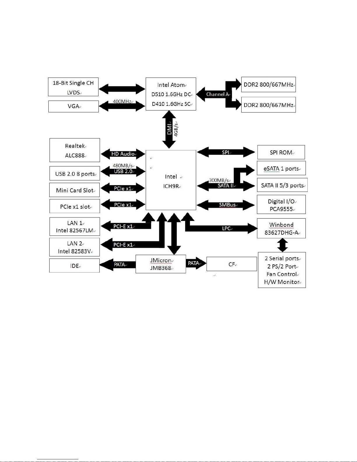
Block Diagram
Page 10

IXBDN-D510/D410
10
This chapter describes the main board
features and the new technologies
it supports.
Product
introduction
Product
introduction
Page 11

User’s Manual
IXBDN-D510/D410
11
Production Introduction
1.1 Before you Proceed
Take note of the following precautions before you install motherboard components or
change any motherboard settings.
Unplug the power cord from the wall socket before touching any
component.
Use a grounded wrist strap or touch a safely grounded object or a
metal object, such as the power supply case, before handling
components to avoid damaging them due to static electricity
Hold components by the edges to avoid touching the ICs on
them.
Whenever you uninstall any component, place it on a grounded
antistatic pad or in the bag that came with the component.
Before you install or remove any component, ensure that the ATX
power supply is switched off or the power cord is detached from
the power supply. Failure to do so may cause severe damage to
the motherboard, peripherals, and/or components.
Page 12
IXBDN-D510/D410
12
1.2 Motherboard Overview
Before you install the motherboard, study the configuration of your chassis to ensure that
the motherboard fits into it. Refer to the chassis documentation before installing the
motherboard.
Make sure to unplug the power cord before installing or removing the
motherboard. Failure to do so can cause you physical injury and
damage motherboard components.
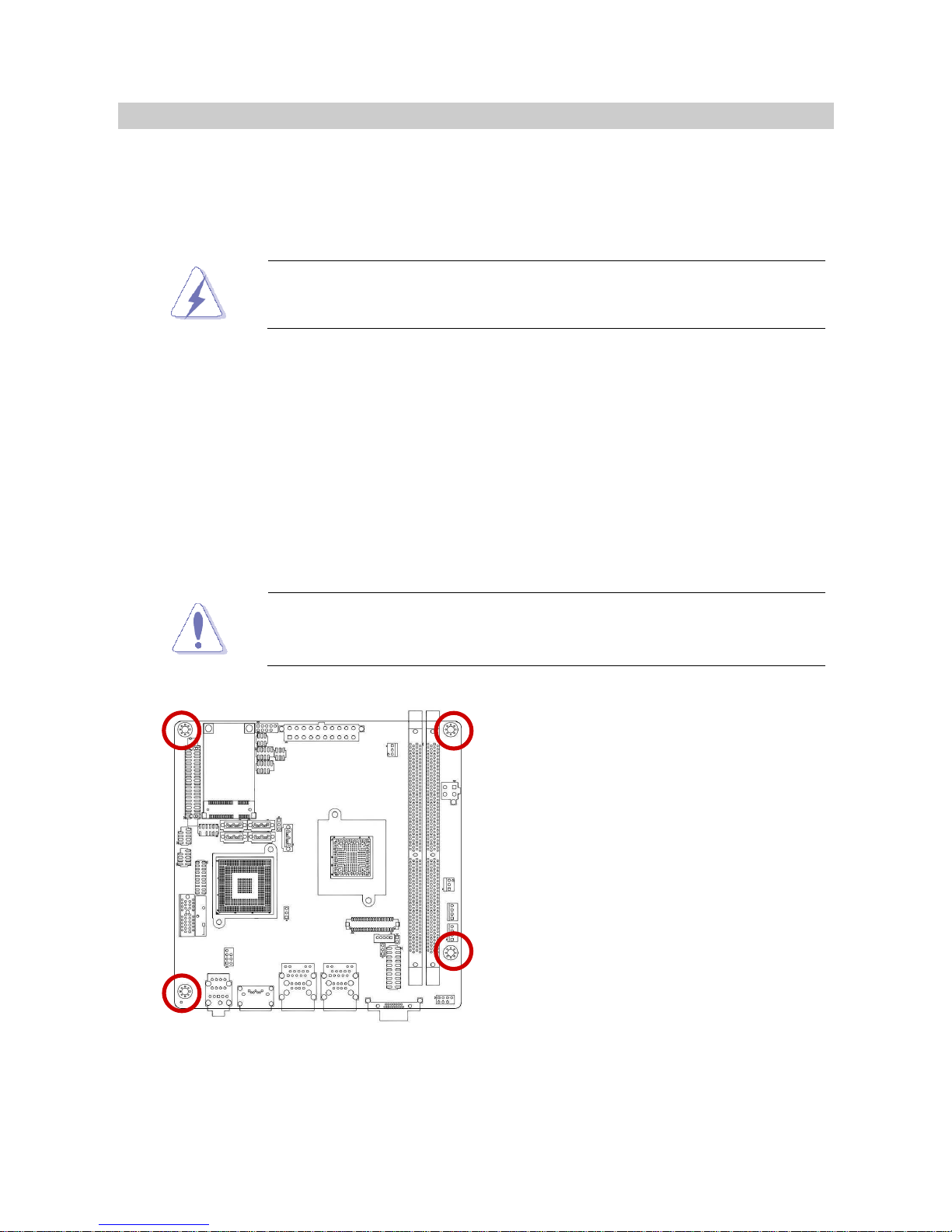
1.2.1 Placement Direction
When installing the motherboard, make sure that you place it into the chassis in the correct
orientation. The edge with external ports goes to the rear part of the chassis as indicated in
the image below.
1.2.2 Screw Holes
Place four (4) screws into the holes indicated by circles to secure the motherboard to the
chassis.
Do not over tighten the screws! Doing so can damage the
motherboard.
Place this side towards the rear of the
chassis.
Page 13

User’s Manual
IXBDN-D510/D410
13
1.3 Motherboard Layout
Page 14
IXBDN-D510/D410
14
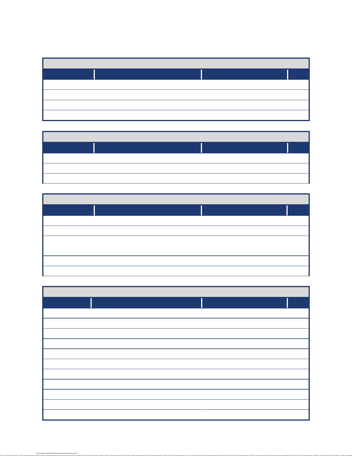
1.3.1 Layout Content List
Slots
Label Function Note Page
XMM1 & 2 240-pin DDR2 DIMM slot 15
MINIPCIE1 Mini PCI-e Slot 18
PCIEX1_1 PCI Express x1 Slot
CF1 Compact Flash Card (Rear side) N/A
Jumpers
Label Function Note Page
CLRTC1 Clear CMOS 3 x 1 header, pitch 2.54mm 19
CLRTC2 Backlight 3.3V/5V Select 3 x 1 header, pitch 2.54mm 19
JCOMPWR1&2 COM1 RI/+5V/+12V Select 3 x 2 header, pitch 2.00mm 20
Rear Panel Connector
Label Function Note Page
VGA1 VGA Connector D-Sub 15-pin, Female 21
USB1 USB 1&2 Connector 21
LANUSB1& 2 RJ-45 Ethernet Connector x1
USB Connector x2
21
Audio1 Audio Line-out Port 21
ESATA1 External SATA Connector 21
Internal Connector
Label Function Note Page
CPUFAN1 CPU Fan Connector 3 x 1 wafer, pitch 2.54mm 22
SYSFAN1 System Fan Connector 3 x 1 wafer, pitch 2.54mm 22
LVDS1 LVDS Connector Hirose DF13S-40DP-1.25V 22
BKL1 LCD Inverter Connector 5 x 1 header, pitch 2.00mm 23
F_PANEL1 System Panel
Connector (USB 5&6)
8 x 2 header, pitch 2.00mm 24
KBMS1 PS/2 keyboard and mouse 4 x 2 header, pitch 2.54mm 25
COM1 & 2 Serial Port Connector * 2 5 x 2 header, pitch 2.00mm 25
CN2 Digital I/O Connector 10 x 2 header,pitch 2.54mm 25
SATA1,2,3,4,5 SATA Data Connector * 5 7P Male connector 26
PATA1 IDE 44-pin Connector
USB4 & 5 USB 4&5 Connector 5 x 2 header, pitch 2.00mm 27
Page 15

User’s Manual
IXBDN-D510/D410
15
1.4 System Memory
2.3.11.1 Overview
The motherboard comes with two 200-pin Double Data Rate 2 (DDR2) SODIMM sockets.
A DDR2 module has the same physical dimensions as a DDR DIMM but has a 240-pin
footprint compared to the 184-pin DDR DIMM. DDR2 DIMMs are notched differently to
prevent installation on a DDR DIMM socket. The following figure illustrates the location of
the sockets:
Page 16

IXBDN-D510/D410
16
1.4.2 Memory Configurations
You can install 256MB, 512MB, 1GB and 2GB DDR2 SDRAM DIMMs into the DIMM
sockets using the memory configurations in this section.
Installing DDR2 DIMM other than the recommended
configurations may cause memory sizing error or system boot
failure. Use any of the recommended configurations.
Due to chipset graphic resource allocation, the system may
detect less than 2 GB system memory when you installed one 2
GB DDR2 memory modules.
This motherboard does not support memory modules FSB less
than 667MHz.Make sure that the memory frequency matches the
CPU FSB (Front Side Bus). Refer to the Memory frequency/CPU
FSB synchronization table.
1.4.3 Installing a DDR2 DIMM
Make sure to unplug the power supply before adding or removing
DIMMs or other system components. Failure to do so may cause
severe damage to both the motherboard and the components.
1. Locate the DIMM socket on the board.
2. Hold two edges of the DIMM module carefully, and keep away of touching its
connectors.
3. Align the notch key on the module with the rib on the slot.
4. Firmly press the modules into the socket which will automatically snap into the mounting
notch. Do not force the DIMM module in with extra force as the DIMM module only fits in
one direction.
Page 17
User’s Manual
IXBDN-D510/D410
17
A DDR2 DIMM is keyed with a notch so that it fits in only one
direction. DO NOT force a DIMM into a socket to avoid damaging
the DIMM.
The DDR2 DIMM sockets do not support DDR/DDR3 DIMMs.
DO NOT install DDR/DDR3 DIMMs to the DDR2 DIMM socket.
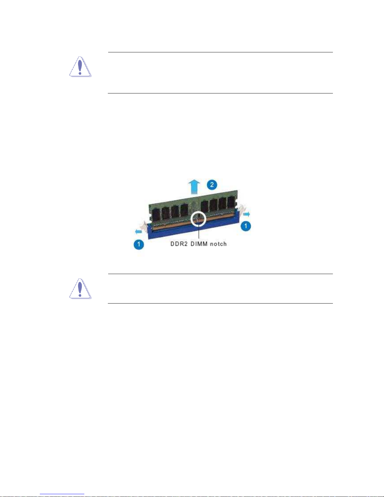
1.4.4 Removing a DDR2 DIMM
1. Press the two ejector tabs on the slot outward simultaneously, and then pull out the
DIMM module.
Support the DIMM lightly with your fingers when pressing the ejector
tabs. The DIMM might get damaged when it flips out with extra force.
Page 18
IXBDN-D510/D410
18
1.5 Expansion slots
1.5.1 MiniPCE Express Location
In the future, you may need to install expansion cards. The following sub-sections describe
the slots and the expansion cards that they support.
Make sure to unplug the power cord before adding or removing
expansion cards. Failure to do so may cause you physical injury and
damage motherboard components.
1.5.2 Installing an Expansion Card
1. Before installing the expansion card, read the documentation that came with it and
make the necessary hardware settings for the card.
2. Remove the system unit cover (if your motherboard is already installed in a chassis).
3. Remove the bracket opposite the slot that you intend to use. Keep the screw for later
use.
4. Align the card connector with the slot and press firmly until the card is completely seated
on the slot.
5. Secure the card to the chassis with the screw you removed earlier.
6. Replace the system cover.
1.5.3 Configuring an Expansion Card
After installing the expansion card, configure it by adjusting the software settings.
1. Turn on the system and change the necessary BIOS settings, if any. See Chapter 2 for
information on BIOS setup.
2. Assign an IRQ to the card if needed. Refer to the tables on the next page.
Page 19

User’s Manual
IXBDN-D510/D410
19
3. Install the software drivers for the expansion card.
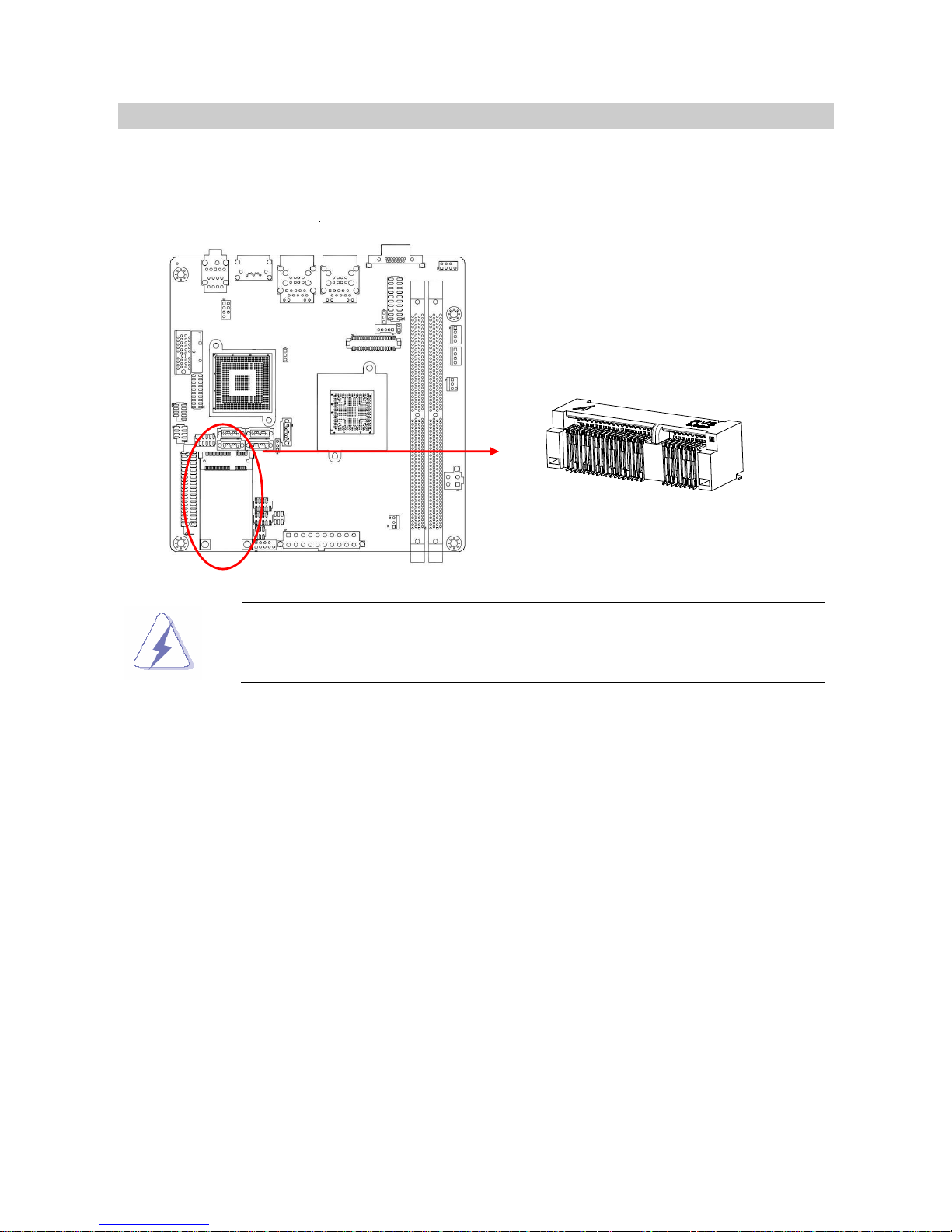
1.5.4 Mini PCI express Slot
The miniPCI express slot supports Mini cards for WiFi , Bluetooth, SSD, COM, USB
modules, and other cards that comply with the mini Card Rev. 1.2 specifications . The figure
below shows the type of full size SSD card that can be installed on a miniPCI express slot.
Due to different pin definitions between mini Card Rev. 1.0 to 1.1/1.2 ,
some Rev.1.0 mini Cards may not work normally on this MiniPCI express
slot .
1.5.5 PCI Express x1
This motherboard supports PCI Express x1 network
cards, SCSI cards and other cards that comply with
the PCI Express specifications. The figure shows the
type of network card that can be installed on the PCI
Express x1 slot.
1.5.6 PCI Slots
IX45GM has one PCI slots. The PCI slots support
cards such as a LAN card, SCSI card, USB card,
and other cards that comply with PCI specifications.
The figure shows a LAN card installed on a PCI slot.
Page 20

IXBDN-D510/D410
20
1.6 Jumpers
1.6.1 Clear CMOS (CLRTC1)
This jumper allows you to clear the Real Time Clock (RTC) RAM in CMOS. You can clear
the CMOS memory of date, time, and system setup parameters by erasing the CMOS RTC
RAM data. The onboard button cell battery powers the RAM data in CMOS, which include
system setup information such as system passwords. To erase the RTC RAM:
1. Turn OFF the computer and unplug the power cord.
2. Remove the onboard battery.
3. Move the jumper cap from pins 1-2 (default) to pins 2-3. Keep the cap on pins 2-3 for
about 5~10 seconds, then move the cap back to pins 1-2.
4. Re-install the battery.
5. Plug the power cord and turn ON the computer.
6. Hold down the <Del> key during the boot process and enter BIOS setup to re-enter
data.
Except when clearing the CMOS, never remove the cap on the
CLRTC jumper default position. Removing the cap will cause system
boot failure!
Normal (Default)
1
Clear CMOS
1
Page 21

User’s Manual
IXBDN-D510/D410
21
1.6.2 COM1, COM2 RI/+5V/+12V Select (JCOMPWR1, JCOMPWR2)
RI (Default)
55
6
+5V
55
6
+12V
55
6
1.7 Connectors
1.7.1 Rear Panel Connectors
1 2 3 4 5
Page 22

IXBDN-D510/D410
22
No Label Function Description
1 VGA11 VGA Connector This 15-pin port is for a VGA monitor or
other VGA-compatible devices.
2 3 LAN_USB1,
LAN_USB2
LAN (RJ-45) connector
This port allows Gigabit connection to a
Local Area Network (LAN) through a
network hub. Refer to the table below for
the LAN port LED indications. The optional
10/100/1000 Mbps LAN controller allows
10/100/1000 Mbps connection to a Local
Area Network (LAN) through a network hub.
SPEED LED ACT / LINK LED
Status Description Status Description
OFF 10Mbps connection OFF No link
Orange 100Mbps connection Green Link
Green 1Gbps connection Blinking Data activity
4 ESATA1
External
SATA connector This port connects a external SATA
enclosure or chassis.
5 Audio1 Audio Line-out Port This port connects a headphone or a
speaker. In 4-channel, 6-channel, and
8-channel configuration, the function of this
port becomes Front Speaker Out.
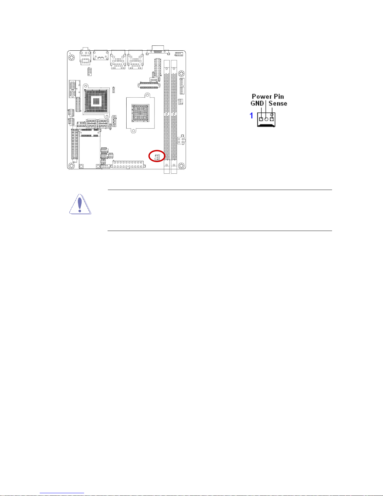
1.7.2 CPU Fan Connector (CPUFAN1)
This connector supports 12V smart fan for onboard heat-sink.
Page 23
User’s Manual
IXBDN-D510/D410
23
Do not forget to connect the fan cable to the fan connector.
Insufficient air flow inside the system may damage the
motherboard components.
This is not a jumper! DO NOT place a jumper cap on the fan
connector.
1.7.3 LVDS Connector (LVDS1)
This motherboard supports 18-bit single channel LVDS panel.
Page 24

IXBDN-D510/D410
24
1.7.4 LCD Inverter Connector (BKL1)
This function will support the control of internal LVDS brightness.
Page 25

User’s Manual
IXBDN-D510/D410
25
Signal Description
Signal Signal Description
VR For inverter with adjustable Backlight
function, it is possible to control the LCD
brightness through the VR signal.
Vadj=0.75V ~ 4.25V
(Recommended: 4.7KΩ, > 1/16W)
ENBKL LCD backlight ON/OFF control signal
1.7.5 System Panel Connector (F_PANEL1)
This connector supports several chassis-mounted functions, and provides additional USB 5
& 6 ports.
Page 26

IXBDN-D510/D410
26
System Power LED (2-pin PWRLED)
This 2-pin connector is for the system power LED. Connect the chassis power LED
cable to this connector. The system power LED lights up when you turn on the system
power, and blinks when the system is in sleep mode.
ATX Power Button/Soft-off Button (2-pin PWRSW)
This connector is for the system power button. Pressing the power button turns the
system on or puts the system in sleep or soft-off mode depending on the BIOS settings.
Pressing the power switch for more than four seconds while the system is ON turns the
system OFF.
Hard Disk Drive Activity LED (2-pin HDLED)
This 2-pin connector is for the HDD Activity LED. Connect the HDD Activity LED cable
to this connector. The IDE LED lights up or flashes when data is read from or written to
the HDD.
Reset Button (2-pin RESET)
This 2-pin connector is for the chassis-mounted reset button for a system reboot
without turning off the system power.
Page 27
User’s Manual
IXBDN-D510/D410
27
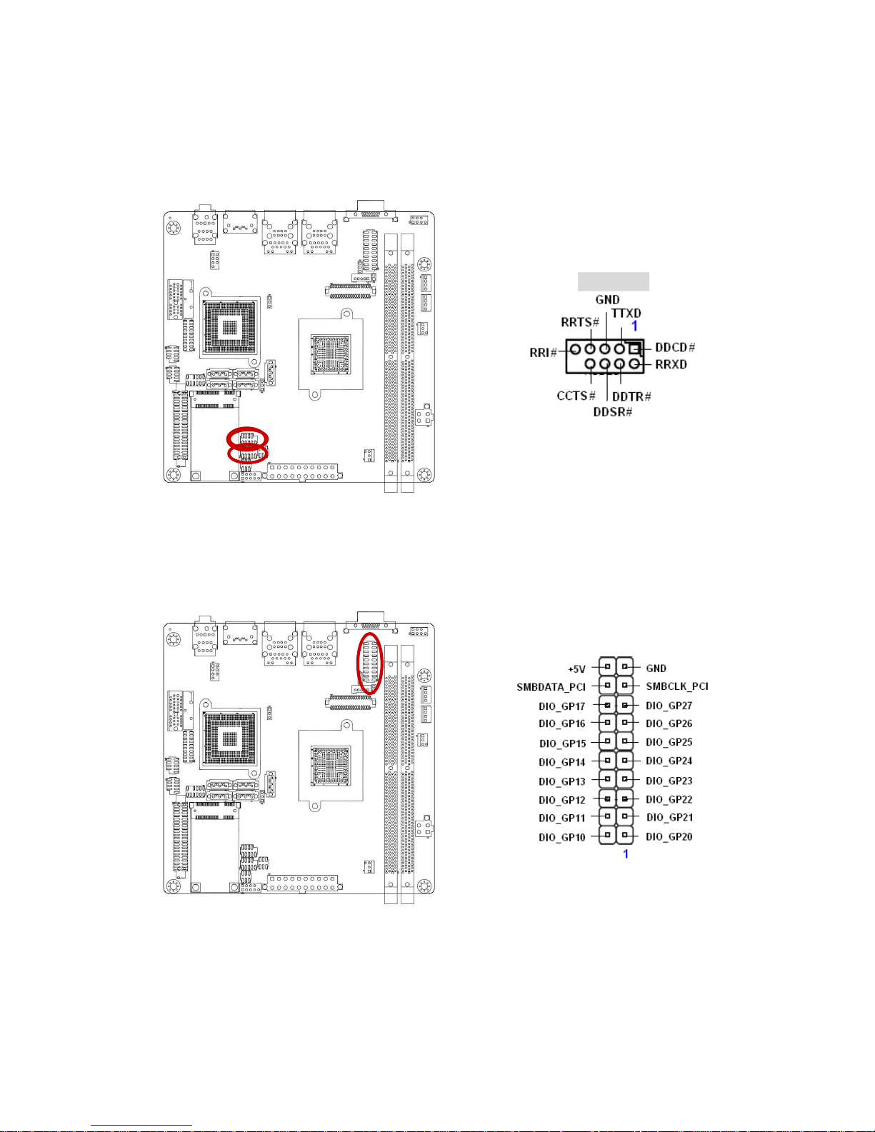
1.7.6 Serial Port Connector (COM1 & COM2 )
These 2 connectors are for serial (COM) port. Connect the serial port module cable to this
connector, and then install the module to a slot opening at the back of the system chassis.
COM 1&2
1.7.7 Digital I/O Connector (JDIO)
This connector supports 8-bit General purpose I/O function.
Page 28

IXBDN-D510/D410
28
1.7.8 SATA Data Connector (SATA1, SATA2, SATA 3)
These connectors are for the SATA signal cables to link SATA hard disk drives.
SATA 1
SATA 2
SATA 3
This connector is for the provided SATA power cable. This power supply cable is designed
to fit this connector in only one orientation. Find the proper orientation and push down firmly
until the connector completely fits.
SATA4
SATA2
SATA3
SATA1
SATA5
12V
GND
GND
5V
Page 29
User’s Manual
IXBDN-D510/D410
29
This 1x4P connector is for SATA power supply, plugging-in an
Floppy 1x4P power cable from PSU will damage this
motherboard .
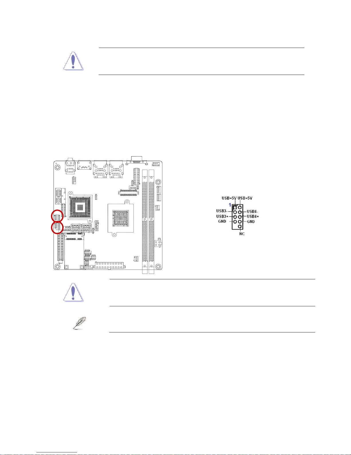
1.7.9 USB 2.0 Connector (USB4, USB5)
This connector is for USB 2.0 ports. Connect the USB/GAME module cable to any of these
connectors, and then install the module to a slot opening at the back of the system chassis.
This USB connector complies with USB 2.0 specification that supports up to 480 Mbps
connection speed.
Never connect a 1394 cable to the USB connectors. Doing so will
damage the motherboard!
The USB module is purchased separately.
 Loading...