

Page 1

IX45GM
Intel® GM45 socket 479P Core Duo / Core Solo/Core 2
Duo Mini-ITX Motherboard
User’s Manual
Ver. 1.20
Page 2

IX45GM
2
Contents
Safety Information .......................................................................................................... 4
Technical Support ............................................................................................................ 5
Conventions Used in This Guide .................................................................................... 5
Packing List ....................................................................................................................... 6
Revision History ............................................................................................................... 7
Specifications Summary .................................................................................................. 8
Block Diagram ................................................................................................................. 11
Production Introduction ............................................................................................... 13
1.1 Before you Proceed ................................................................................................ 13
1.2 Motherboard Overview ............................................................................................ 14
1.2.1 Placement Direction ....................................................................................................................... 14
1.2.2 Screw Holes ................................................................................................................................... 14
1.3 Motherboard Layout ................................................................................................ 15
1.3.1 Layout Content List ........................................................................................................................ 16
1.4 Central Processing Unit (CPU)................................................................................ 18
1.4.1 Installing the CPU ........................................................................................................................... 19
1.4.2 Installing the CPU Heatsink and Fan ............................................................................................. 21
1.4.3 Uninstalling the CPU Heatsink and Fan ......................................................................................... 23
1.5 System Memory ...................................................................................................... 24
1.5.1 SO-DIMM Sockets Location ........................................................................................................... 24
1.5.2 Memory Configurations .................................................................................................................. 25
1.5.3 Installing a DDR2 SO-DIMM .......................................................................................................... 26
1.5.4 Removing a DDR2 SO-DIMM ........................................................................................................ 27
1.6 Expansion Slots ...................................................................................................... 28
1.6.1 Installing an Expansion Card ......................................................................................................... 28
1.6.2 Configuring an Expansion Card ..................................................................................................... 28
1.6.3 Standard Interrupt Assignments ..................................................................................................... 29
1.6.4 PCI Slots ........................................................................................................................................ 30
1.6.5 PCI Express x1 Slots ...................................................................................................................... 30
1.6.6 Mini PCI Express Slots ................................................................................................................... 30
1.7 Jumpers .................................................................................................................. 31
1.7.1 Clear CMOS (CCMOS1) ................................................................................................................ 31
1.7.2 COM1 RI/+5V/+12V Selection (JCOMPWR3) ............................................................................... 32
1.7.3 COM2 RI/+5V/+12V Selection (JCOMPWR2) ............................................................................... 32
Page 3

User’s Manual
IX45GM
3
Contents
1.8 Connectors .............................................................................................................. 33
1.8.1 Rear Panel Connectors .................................................................................................................. 33
1.8.2 Amplifier Connector (AMPJ1) ......................................................................................................... 35
1.8.3 Serial Port 2-3 Connector (COM2, COM3) .................................................................................... 36
1.8.4 Serial Port 4-5 Connector (COM4, COM5) .................................................................................... 36
1.8.5 CPU Fan Connector (CPU_FAN1) ................................................................................................. 37
1.8.6 System Fan Connector (SYS_FAN1) ............................................................................................. 37
1.8.7 System Panel Connector (FPIO1) .................................................................................................. 38
1.8.8 Digital I/O Connector ...................................................................................................................... 39
1.8.9 LVDS Connector (JLVDS1) ....................................................................................................... 39
1.8.10 LCD Inverter Connector (JBKL1) ............................................................................................... 40
1.8.11 SPI Connector (JSPI1) ............................................................................................................... 41
1.8.12 Digital Audio Connector (SPDIF_OUT1) ................................................................................... 41
1.8.13 Serial SATA Connector (SATA1, SATA2, SATA3, SATA4) ...................................................... 42
1.8.14 SATA Power Connector (SATA_POWER1, SATA_POWER2) ................................................. 43
1.8.15 USB 2.0 Connector (USB1, USB2) ............................................................................................ 43
Page 4

IX45GM
4
Safety Information
Electrical safety
z To prevent electrical shock hazard, disconnect the power cable from the electrical
outlet before relocating the system.
z When adding or removing devices to or from the system, ensure that the power cables
for the devices are unplugged before the signal cables are connected. If possible,
disconnect all power cables from the existing system before you add a device.
z Before connecting or removing signal cables from the motherboard, ensure that all
power cables are unplugged.
z Seek professional assistance before using an adapter or extension cord. These
devices could interrupt the grounding circuit.
z Make sure that your power supply is set to the correct voltage in your area. If you are
not sure about the voltage of the electrical outlet you are using, contact your local
power company.
z If the power supply is broken, do not try to fix it by yourself. Contact a qualified service
technician or your retailer.
Operation safety
z Before installing the motherboard and adding devices on it, carefully read all the
manuals that came with the package.
z Before using the product, make sure all cables are correctly connected and the power
cables are not damaged. If you detect any damage, contact your dealer immediately.
z To avoid short circuits, keep paper clips, screws, and staples away from connectors,
slots, sockets and circuitry.
z Avoid dust, humidity, and temperature extremes. Do not place the product in any area
where it may become wet.
z Place the product on a stable surface.
z If you encounter technical problems with the product, contact a qualified service
technician or your retailer.
The symbol of the crossed out wheeled bin indicates that the product
(electrical and electronic equipment) should not be placed in
municipal waste. Check local regulations for disposal of electronic
products.
Page 5

User’s Manual
IX45GM
5
Technical Support
If a problem arises with your system and no solution can be obtained from the user’s
manual, please contact your place of purchase or local distributor. Alternatively, please try
the following help resources for further guidance. Visit the BCM TW website for FAQ,
technical guide, BIOS updates, driver updates, and other information:
http://www.bcmimb.com.tw
Conventions Used in This Guide
To make sure that you perform certain tasks properly, take note of the following symbols
used throughout this manual.
DANGER/WARNING: Information to prevent injury to yourself when
trying to complete a task.
CAUTION: Information to prevent damage to the components when
trying to complete a task.
IMPORTANT: Instructions that you MUST follow to complete a task.
NOTE: Tips and additional information to help you complete a task.
Page 6

IX45GM
6
Packing List
Before you begin installing your single board, please make sure that the following materials
have been shipped:
9 1 x Intel 80I-GM4501-10000B2 IX45GM Mini-ITX Motherboard
9 1 x CD-ROM contains the followings:
- User’s manual (this manual in PDF file)
- Drivers
9 1 x 14GS000073V04 COM1+2 cable (9-pin w/o bracket, 30cm, 1.0mm pitch)
9 2 x 14G000127073 SATA cable
9 1x 14GS1400018V04 SATA 2in1 Power Cable
9 1 x I/O Shield
9 6 x 4# Screws
9 1 x Startup Manual
If any of the above items is damaged or missing, please contact your
retailer.
Page 7

User’s Manual
IX45GM
7
Revision History
Revision Revision History Date
V 1.0 First release for PCB 1.00 July 11, 2009
Page 8
IX45GM
8
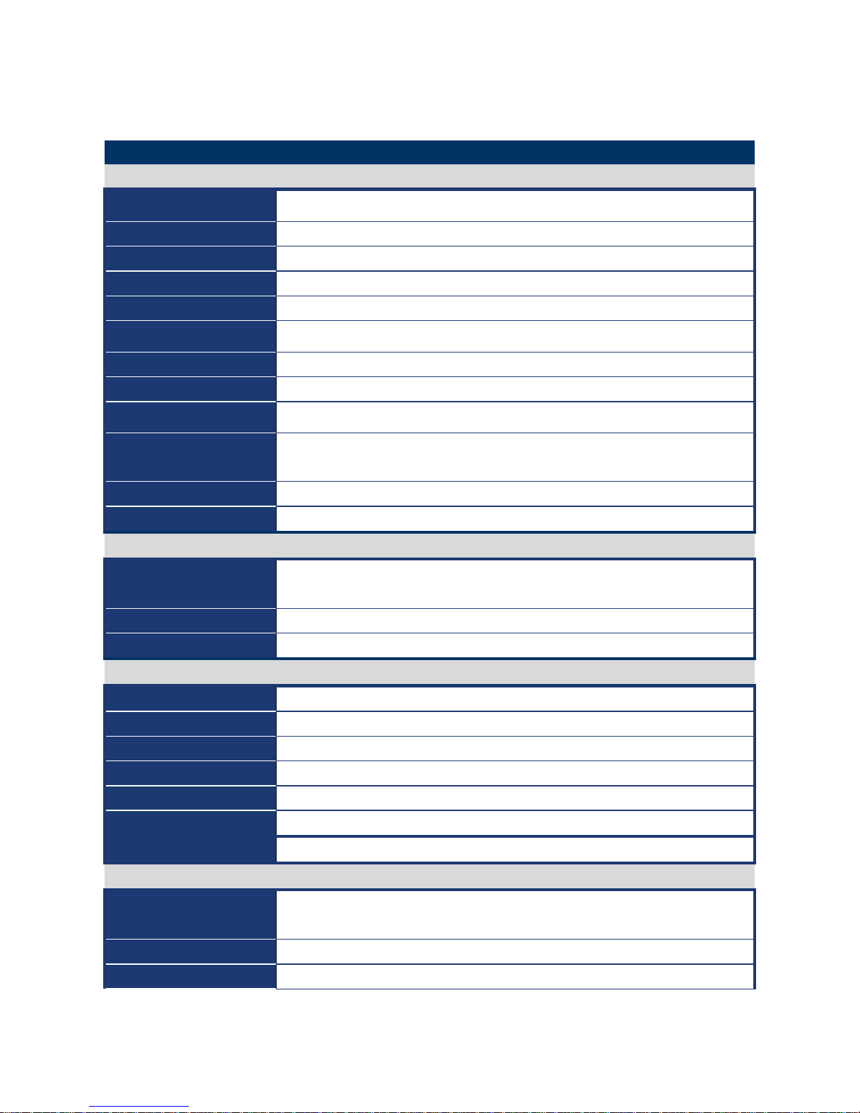
Specifications Summary
Specifications
System
CPU
Supports Intel socket P Core 2 Duo / Core Duo / Core 2 Solo / Core Solo mobile
CPU with 45nm process technology
FSB
667/800/1066 MHz
BIOS
AMI 32Mb SPI BIOS
System Chipset
Intel GM45/ICH9M-E
I/O Chipset
Winbond W83627DHG-A
Memory
2 x 200-pin SODIMM socket supports up to 4 GB Dual channel DDR2 533/667
SDRAM
CompactFlash
One CompactFlash Type I/II socket (optional)
Watchdog Timer
Reset: 1 sec.~255 min. and 1 sec. or 1 min./step
H/W Status Monitor
Monitoring CPU temperature, voltage, and cooling fan status. Auto throttling
control when CPU overheats
Expansion Slots
1 x PCI slot (PCI Rev.2.2 compliant) supports 3 PCI master
1x PCI-E x1 Slot
S3
S3 Support
SmartFan Control
Yes
I/O
MIO
4 x SATA, 8 x USB, 4 x RS-232, 1 x K/B, 1 x Mouse (COM1~2 with power
output)
USB
8 x USB 2.0 ports
DIO
8-bit General Purpose I/O for DI and DO
Display
Chipset
Intel Graphics Media Accelerator 4500MHD
Display Memory
Intel DVMT 5.0 supports 384 MB video memory
Resolution
2048 x 1536 @ 32 bpp(@ 60Hz)
Dual Display
CRT + LVDS, or CRT + DVI-D
LVDS
Dual-channel 24-bit LVDS
DVI
Chrontel CH7318C DVI transmitter up to 165M pixels/second
HDMI
TI SN75DP139 DisplayPort to TMDS transmitter
Audio
Audio Codec
Realtek ALC888 Audio Codec
5.1+2 CH. with two independent audio stream
Audio Interface
Mic in, Line in, Line out
Audio Amplifier
TPA3005D2 Stereo 5Watt per channel
Page 9
User’s Manual
IX45GM
9
Ethernet
LAN1
Intel 82567LM Gigabit Ethernet Controller
LAN2
Intel 82574L PCI-E Gigabit Ethernet Controller (optional)
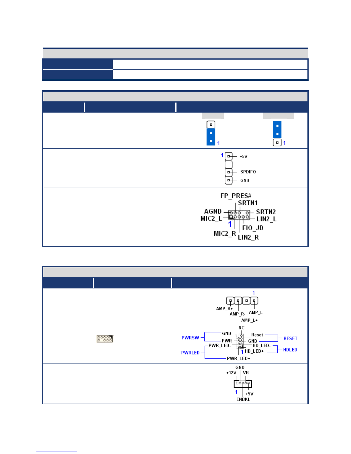
Jumpers
Label Function Note
CLRTC1 Clear CMOS
Normal * Clear CMOS
SPDIF_OUT1
AAFP1 Front Panel Audio
Connector
Connectors
Label Function Note
JAMP1 Amplifier Connector
Panel1 System Panel Connector
JBKL1 LCD Inverter Connector
Page 10
IX45GM
10
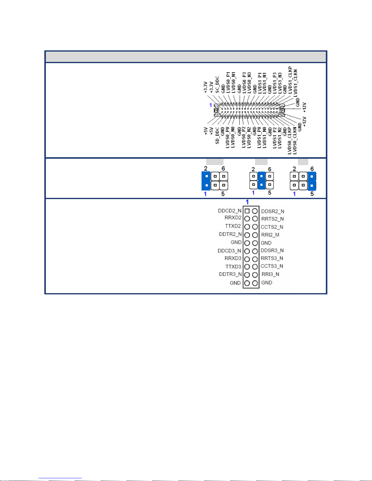
Connectors
JLVDS1 LVDS Connector
COMPWR2
COMPWR3
COM1, COM2 RI/+5V/+12V
Selection
+12V * Ring
+5V
COM23
COM45
COM Connector
* Specifications are subject to change without notice.
Page 11
User’s Manual
IX45GM
11
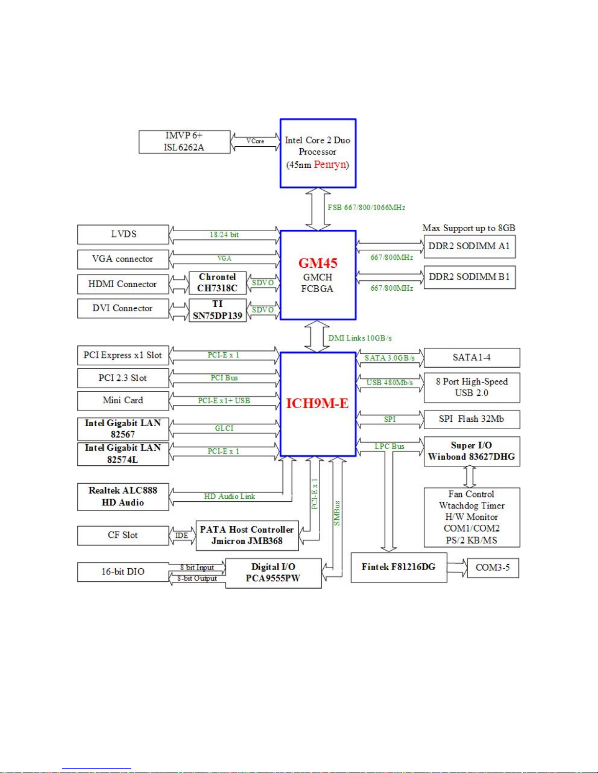
Block Diagram
Page 12

IX45GM
12
This chapter describes the motherboard
features and the new technologies
it supports.
1
Product
introduction
1
Product
introduction
Page 13

User’s Manual
IX45GM
13
Production Introduction
1.1 Before you Proceed
Take note of the following precautions before you install motherboard components or
change any motherboard settings.
z Unplug the power cord from the wall socket before touching any
component.
z Use a grounded wrist strap or touch a safely grounded object or a
metal object, such as the power supply case, before handling
components to avoid damaging them due to static electricity
z Hold components by the edges to avoid touching the ICs on
them.
z Whenever you uninstall any component, place it on a grounded
antistatic pad or in the bag that came with the component.
z Before you install or remove any component, ensure that the ATX
power supply is switched off or the power cord is detached from
the power supply. Failure to do so may cause severe damage to
the motherboard, peripherals, and/or components.
Page 14
IX45GM
14
1.2 Motherboard Overview
Before you install the motherboard, study the configuration of your chassis to ensure that
the motherboard fits into it. Refer to the chassis documentation before installing the
motherboard.
Make sure to unplug the power cord before installing or removing the
motherboard. Failure to do so can cause you physical injury and
damage motherboard components.
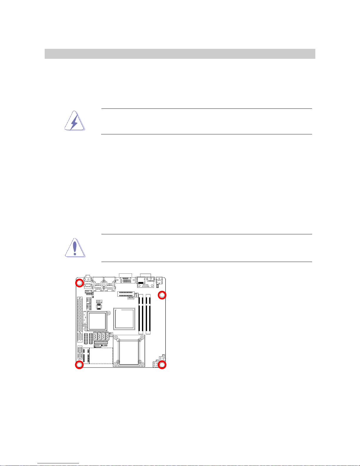
1.2.1 Placement Direction
When installing the motherboard, make sure that you place it into the chassis in the correct
orientation. The edge with external ports goes to the rear part of the chassis as indicated in
the image below.
1.2.2 Screw Holes
Place four (4) screws into the holes indicated by circles to secure the motherboard to the
chassis.
Do not over tighten the screws! Doing so can damage the
motherboard.
Place this side towards the rear
of the chassis
Page 15
User’s Manual
IX45GM
15
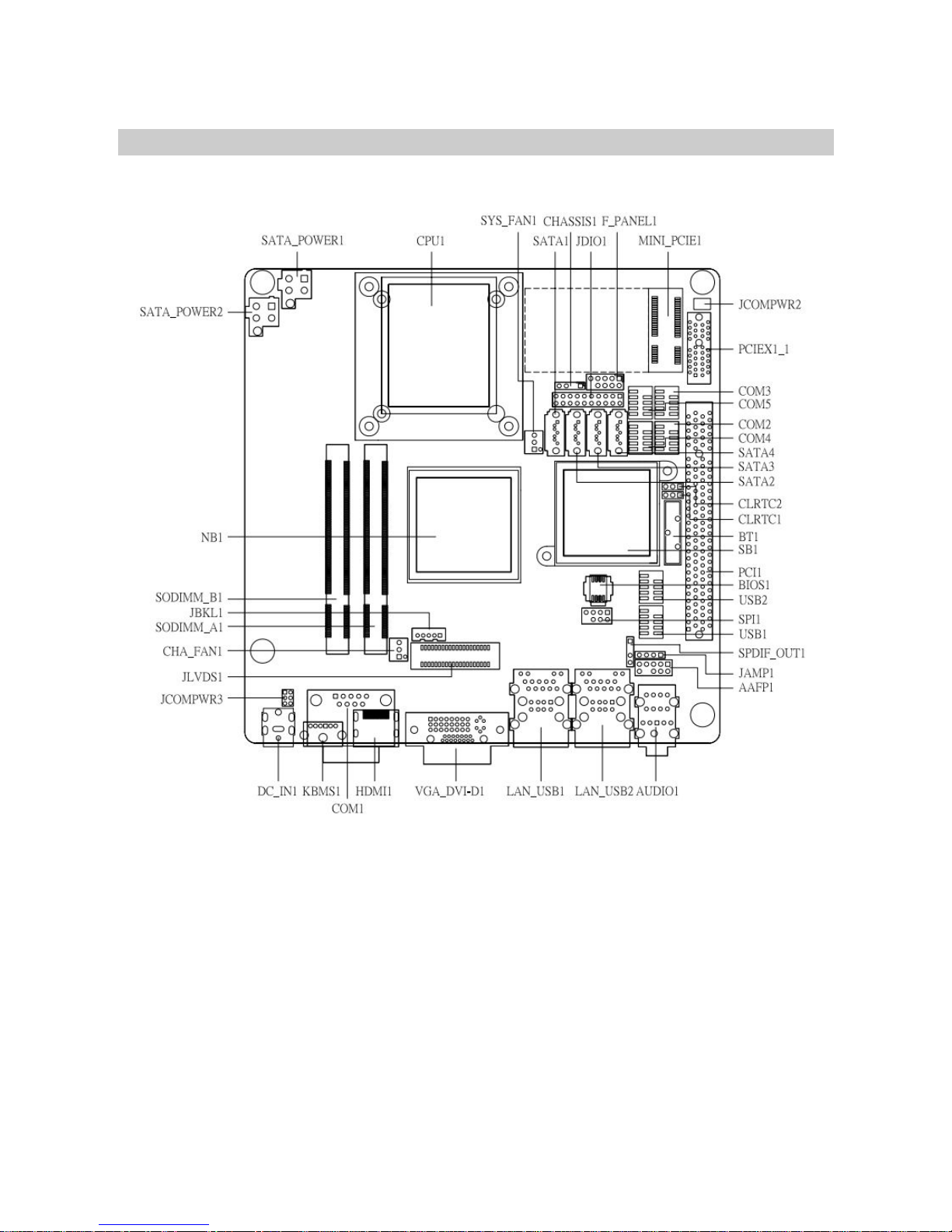
1.3 Motherboard Layout
Page 16
IX45GM
16
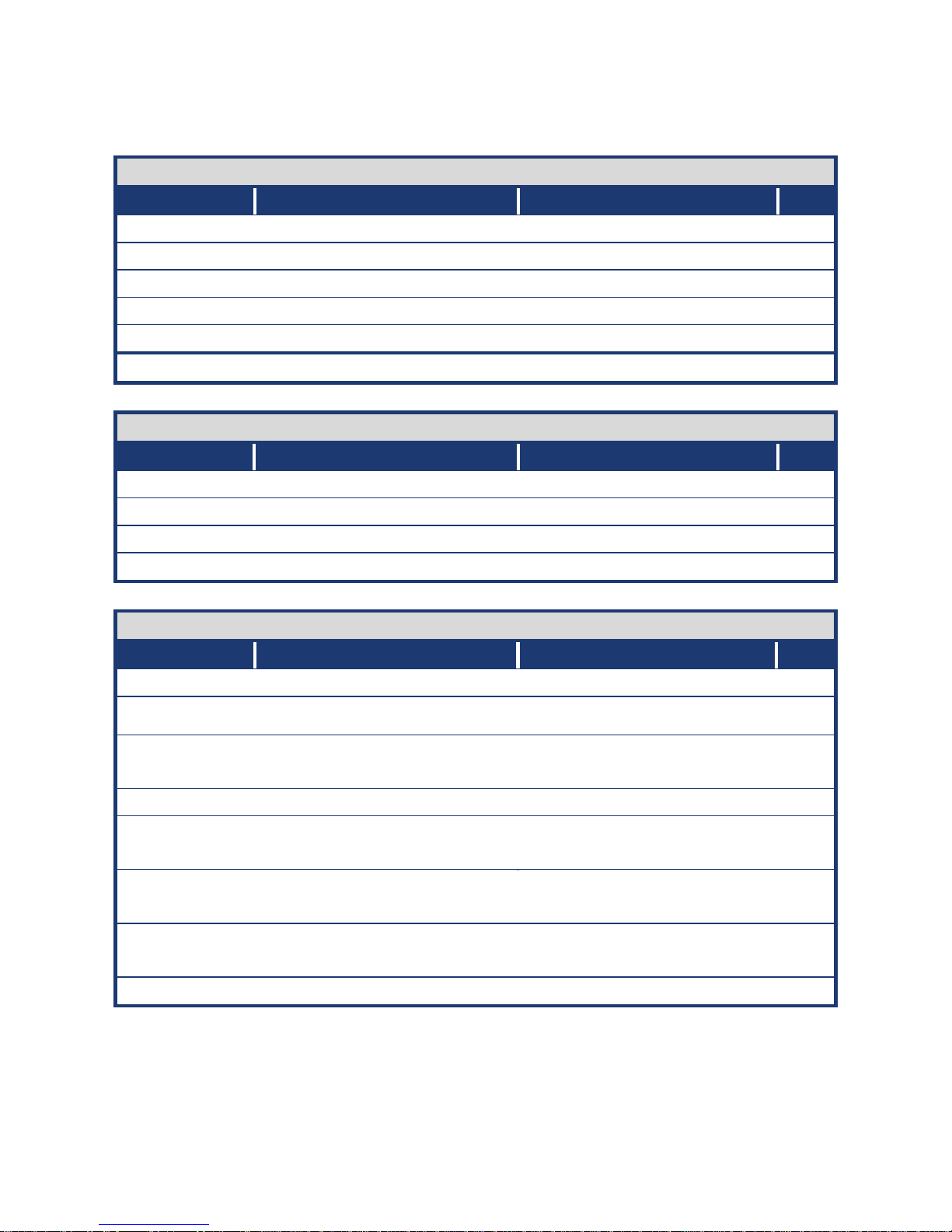
1.3.1 Layout Content List
Slots
Label Function Note Page
CF1A Compact Flash connector (Rear side) N/A
SODIMM_A1 200-pin SODIMM slot 1 24
SODIMM_B1 200-pin SODIMM slot 2 24
PCIEX1_1 PCI Express x1 Slot 30
MINI_PCIE1 Mini PCI Express slot 30
PCI1 PCI slot 30
Jumpers
Label Function Note Page
CLRTC1 Clear CMOS 3 x 1 header, pitch 2.54mm 31
JCOMPWR3 COM 1 RI/+5V/+12V selection 3 x 2 header, pitch 2.00mm 32
JCOMPWR2 COM 2 RI/+5V/+12V selection 3 x 2 header, pitch 2.00mm 32
CHASSIS1 Chassis intrusion 4 x 1 header, pitch 2.54mm 32
Rear Panel Connector
Label Function Note Page
KBMS1 PS/2 keyboard and mouse 6-pin Mini-Din 33
COM1 Serial port connector D-sub 9-pin, male 33
VGA_DVI-D1 VGA connector
DVI connector
D-sub 15-pin, female 33,34
HDMI1 HDMI connector HDMI 19-pin
LAN_USB1 RJ-45 Ethernet connector x 1
USB connector x 2
33,34
LAN_USB2 RJ-45 Ethernet connector x 1
USB connector x 2
33,34
AUDIO1 Line-in port, Line-out port,
Microphone port,
5.1 Channel Audio I/O (3 jacks) 34
DC_IN1 DC-IN Power Jack
Page 17

User’s Manual
IX45GM
17
Internal Connector
Label Function Note Page
JAMP1 Amplifier connector 4 x 1 header, pitch 2.54mm 34
COM23 Serial port 2 & 3 connector 10 x 2 header, pitch 2.00mm 35
COM45 Serial port 4 & 5 connector 10 x 2 header, pitch 2.00mm 35
CPU_FAN1 CPU fan connector 3 x 1 wafer, pitch 2.54mm 36
SYS_FAN1 System fan connector 3 x 1 wafer, pitch 2.54mm 36
FPIO1 System panel connector 5 x 2 header, pitch 2.54mm 37
JDIO1 Digital I/O connector 10 x 2 header, pitch 2.00m 38
JLVDS1 LVDS connector HIROSE DF13S-40DP-1.25V 38
JBKL1 LCD Inverter connector 5 x 1 header, pitch 2.00mm 39
JSPI1 SPI connector 4 x 2 header, pitch 2.54mm 40
SPDIF_OUT1 Digital Audio connector 4 x 1 header, pitch 2.54mm 40
SATA1,2,3,4 Serial ATA connectors 1,2,3,4 7-pin header 41
SATA_POWER1
SATA_POWER2
SATA Power connectors 1,2 4-pin header 42
USB1,2 USB 2.0 connector 5 x 2 header, pitch 2.54mm 42
Page 18
IX45GM
18
1.4 Central Processing Unit (CPU)
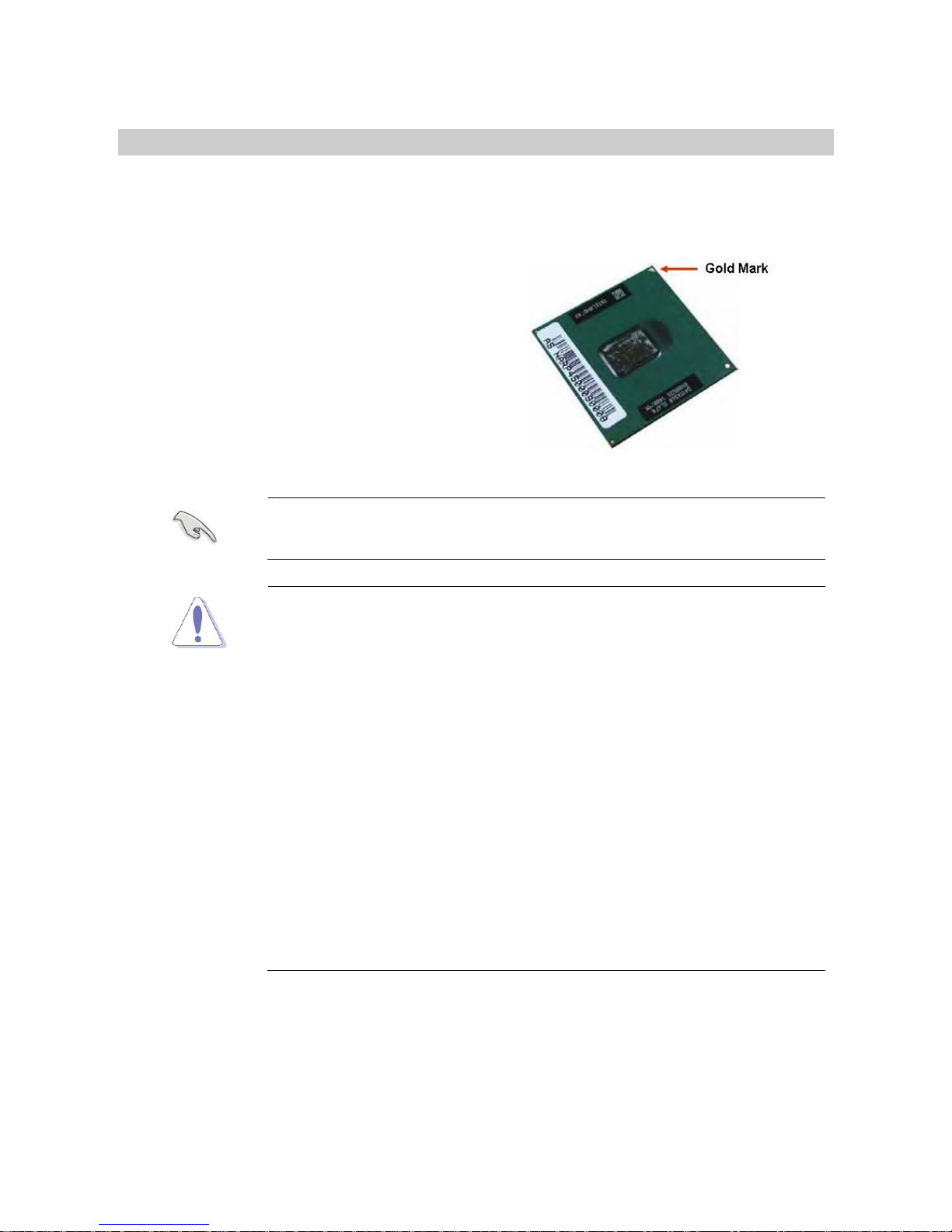
The motherboard comes with a surface mount 478-pin designed for the Intel® socket 479P
Core Duo / Core Solo / Core 2 Duo CPU with 65nm process.
Take one of the marked corner (with gold
triangle) on the CPU. This mark should
match a specific corner on the socket to
ensure correct installation.
z Make sure the AC power is off before you install the CPU.
z If installing a dual-core CPU, connect the CPU fan cable to the
CPU_FAN1 connector to ensure system stability.
z Your boxed Intel® socket 479P Core Duo / Core Solo / Core 2
Duo CPU with 45nm process package should come with
installation instructions for the CPU, heatsink, and the retention
mechanism. If the instructions in this section do not match the
CPU documentation, follow the latter.
z Upon purchase of the motherboard, make sure that the PnP cap
is on the socket and the socket contacts are not bent. Contact
your retailer immediately if the PnP cap is missing, or if you see
any damage to the PnP cap/socket contacts/motherboard
components. Your place of purchase or local distributor will
shoulder the cost of repair only if the damage is
shipment/transit-related.
z Keep the cap after installing the motherboard. Your place of
purchase or local distributor will process Return Merchandise
Authorization (RMA) requests only if the motherboard comes with
the cap on the socket.
z The product warranty does not cover damage to the socket
contacts resulting from incorrect CPU installation/removal, or
misplacement/loss/ incorrect removal of the PnP cap.
Page 19
User’s Manual
IX45GM
19
1.4.1 Installing the CPU
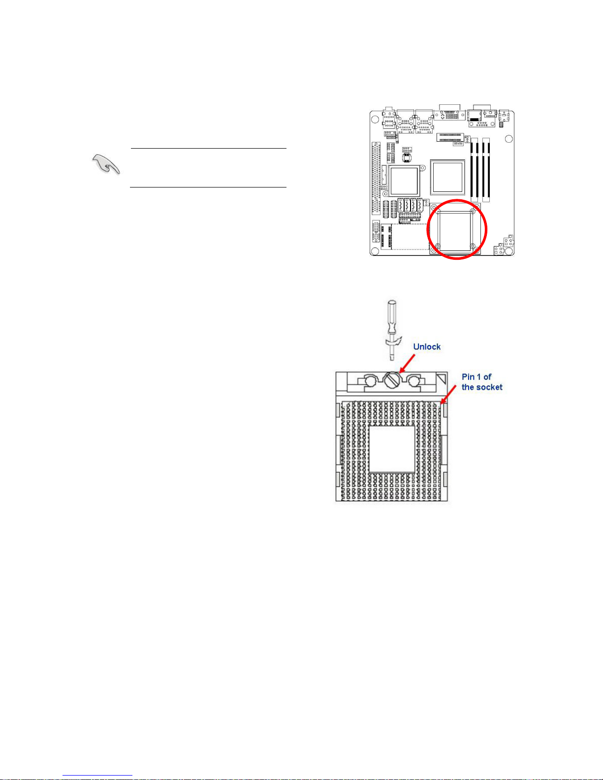
1. Locate the CPU socket on the
motherboard.
Before installing the CPU,
make sure that the socket
box is facing towards you.
2. The processor socket comes with a
screw to secure the processor, please
unlock the screw first.
Page 20
IX45GM
20
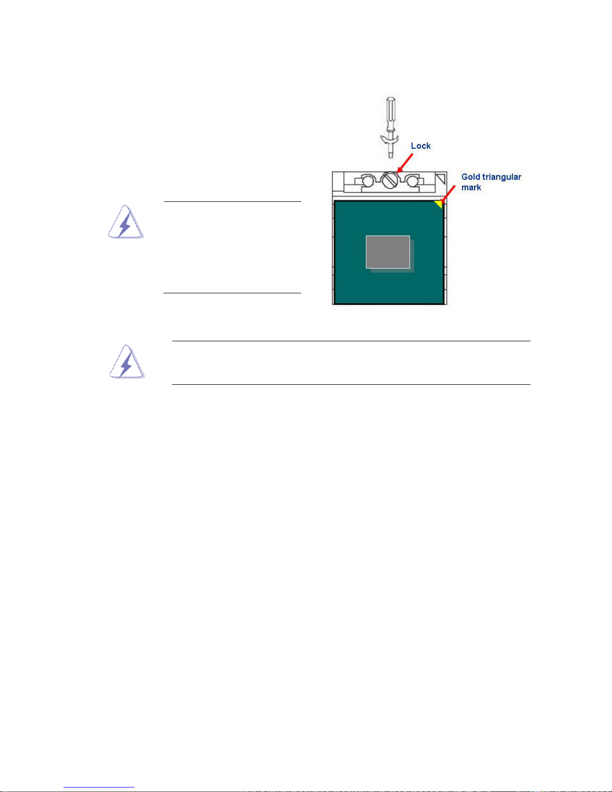
3. Position the CPU above the socket and
the gold triangular mark on the CPU
must align with pin 1 of the CPU socket.
4. Carefully insert the CPU into the socket
until it fits in place ‘Gold mark’.
5. Turn the screw to the lock position.
The CPU fits in only one
correct orientation. DO
NOT force the CPU into
the socket to prevent
bending the connectors
on the socket and
damaging the CPU.
After installation, make sure to plug-in the ATX power cable to the
motherboard.
Page 21
User’s Manual
IX45GM
21
1.4.2 Installing the CPU Heatsink and Fan
The Intel® socket 479P Core Duo / Core Solo / Core 2 Duo CPU processor requires a
specially designed heatsink and fan assembly to ensure optimum thermal condition and
performance.
z Install the motherboard to the chassis before you install the CPU
fan and heatsink assembly.
z When you buy a boxed Intel® processor, the package includes
the CPU fan and heatsink assembly. If you buy a CPU
separately, make sure that you use only Intel®‑certified
multi‑directional heatsink and fan.
If you purchased a separate CPU heatsink and fan assembly, make
sure that you have properly applied Thermal Interface Material to the
CPU heatsink or CPU before you install the heatsink and fan
assembly.
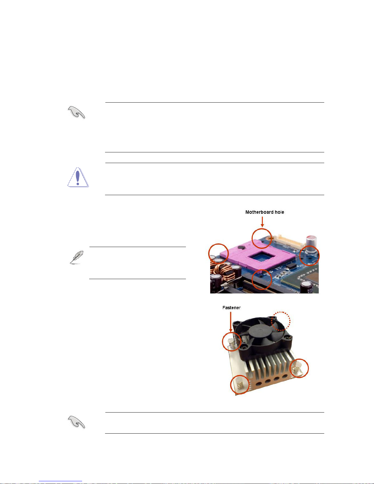
1. Place the heatsink on top of the installed
CPU, making sure that the four fasteners
match the holes on the motherboard.
Orient the heatsink and fan
assembly such that the CPU
fan cable is closest to the
CPU fan connector.
Make sure each fastener is oriented as shown, with the narrow groove
directed outward.
Page 22
IX45GM
22
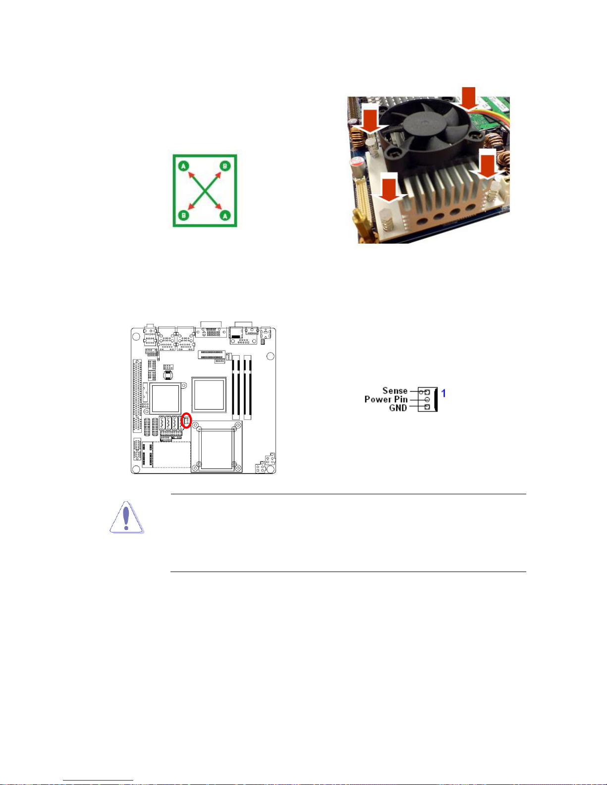
2. Push down two fasteners at a time in a
diagonal sequence to secure the heatsink
and fan assembly in place.
3. Connect the CPU fan cable to the connector on the motherboard labelled
CPU_FAN1.
z Do not forget to connect the fan cables to the fan connectors.
Insufficient air flow inside the system may damage the
motherboard components, and hardware monitoring errors can
occur if you fail to plug this connector.
z These are not jumpers! DO NOT place jumper caps on the fan
connectors.
Page 23
User’s Manual
IX45GM
23
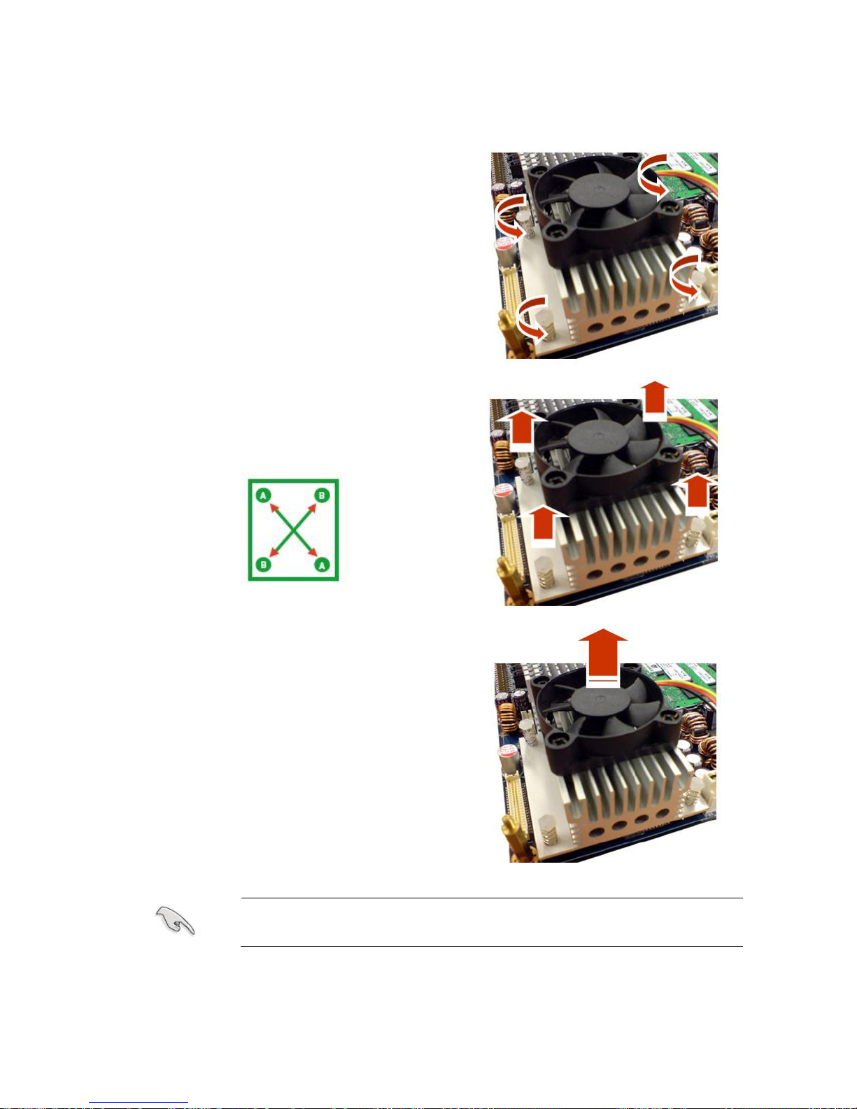
1.4.3 Uninstalling the CPU Heatsink and Fan
1. Disconnect the CPU fan cable from the
connector on the motherboard.
2. Rotate each fastener counterclockwise.
3. Pull up two fasteners at a time in a diagonal
sequence to disengage the heatsink and
fan assembly from the motherboard
4. Carefully remove the heatsink and fan
assembly from the motherboard.
Refer to the documentation in the boxed or stand-alone CPU fan
package for detailed information on CPU fan installation.
Page 24
IX45GM
24
1.5 System Memory
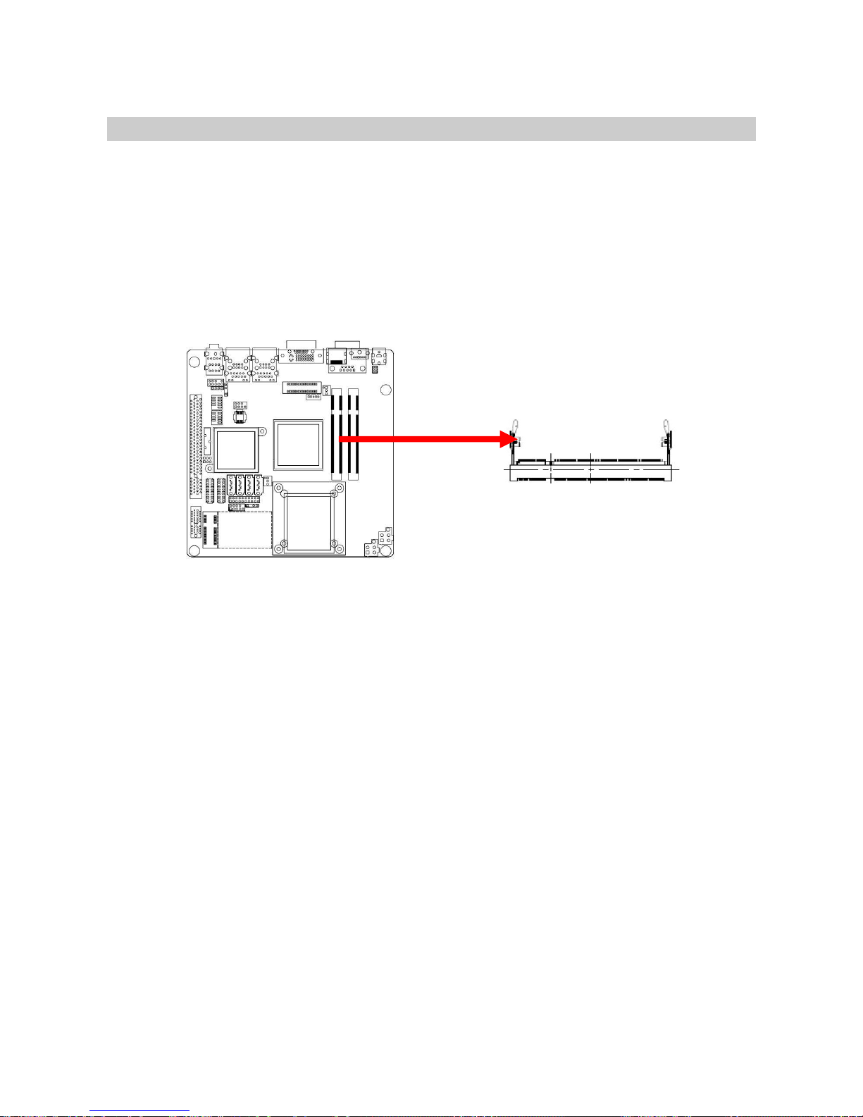
1.5.1 SO-DIMM Sockets Location
The motherboard comes with two 200-pin Double Data Rate 2 (DDR2) SO-DIMM sockets.
A DDR2 module has the same physical dimensions as a DDR SO-DIMM but has a 200-pin
footprint compared to the 184-pin DDR DIMM. DDR2 SO-DIMMs are notched differently to
prevent installation on a DDR SO-DIMM socket. The following figure illustrates the location
of the sockets:
Page 25
User’s Manual
IX45GM
25
1.5.2 Memory Configurations
You can install 128 MB, 256 MB, 512 MB, 1GB and 2GB DDR2 SDRAM SO-DIMMs into
the SO-DIMM sockets using the memory configurations in this section.
z Installing DDR2 SO-DIMM other than the recommended
configurations may cause memory sizing error or system boot
failure. Use any of the recommended configurations.
z Always install SO-DIMMs with the same CAS latency. For
optimum compatibility, it is recommended that you obtain memory
modules from the same vendor.
z Due to chipset resource allocation, the system may detect less
than 1 GB system memory when you installed one 1 GB DDR2
memory modules.
z This motherboard does not support memory modules made up of
128 Mb chips or double-sided x16 memory modules.
Make sure that the memory frequency matches the CPU FSB
(Front Side Bus). Refer to the Memory frequency/CPU FSB
synchronization table.
z Memory frequency/CPU FSB synchronization
CPU FSB DDR 2 DIMM Type Memory Frequency
533/800MHz DDR2 667 Max clock Freq:
333MHZ; 667Mb/s
DDR2 800 Max clock Freq:
400MHZ; 800Mb/s
Page 26
IX45GM
26
1.5.3 Installing a DDR2 SO-DIMM
Make sure to unplug the power supply before adding or removing
SO-DIMMs or other system components. Failure to do so may cause
severe damage to both the motherboard and the components.
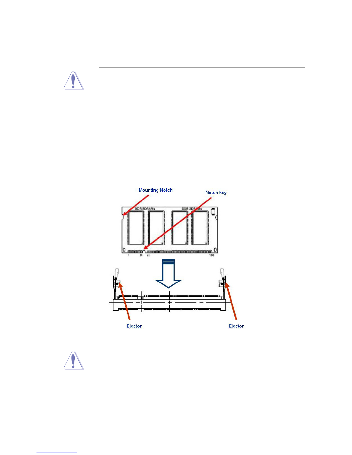
1. Locate the SO-DIMM socket on the board.
2. Hold two edges of the SO-DIMM module carefully, and keep away of touching its
connectors.
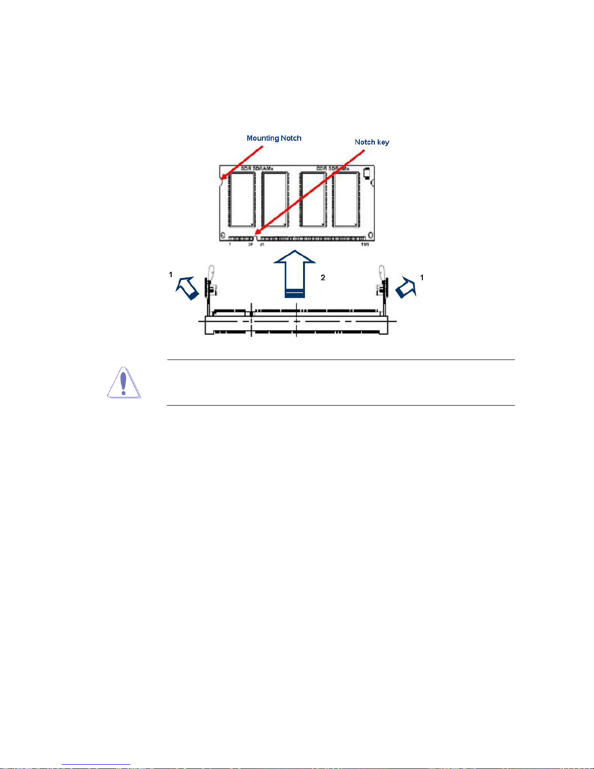
3. Align the notch key on the module with the rib on the slot.
4. Firmly press the modules into the socket automatically snaps into the mounting notch.
Do not force the SO-DIMM module in with extra force as the SO-DIMM module only fit
in one direction.
z A DDR2 SO-DIMM is keyed with a notch so that it fits in only one
direction. DO NOT force a SO-DIMM into a socket to avoid
damaging the SO-DIMM.
z The DDR2 SO-DIMM sockets do not support DDR SO-DIMMs.
DO NOT install DDR SO-DIMMs to the DDR2 SO-DIMM socket.
Page 27
User’s Manual
IX45GM
27
1.5.4 Removing a DDR2 SO-DIMM
1. Press the two ejector tabs on the slot outward simultaneously, and then pull out the
SO-DIMM module.
Support the SO-DIMM lightly with your fingers when pressing the
ejector tabs. The SO-DIMM might get damaged when it flips out with
extra force.
Page 28

IX45GM
28
1.6 Expansion Slots
In the future, you may need to install expansion cards. The following sub‑sections describe
the slots and the expansion cards that they support.
Make sure to unplug the power cord before adding or removing
expansion cards. Failure to do so may cause you physical injury and
damage motherboard components.
1.6.1 Installing an Expansion Card
1. Before installing the expansion card, read the documentation that came with it and
make the necessary hardware settings for the card.
2. Remove the system unit cover (if your motherboard is already installed in a chassis).
3. Remove the bracket opposite the slot that you intend to use. Keep the screw for later
use.
4. Align the card connector with the slot and press firmly until the card is completely
seated on the slot.
5. Secure the card to the chassis with the screw you removed earlier.
6. Replace the system cover.
1.6.2 Configuring an Expansion Card
After installing the expansion card, configure it by adjusting the software settings.
1. Turn on the system and change the necessary BIOS settings if any.
2. Assign an IRQ to the card if needed. Refer to the tables on the next page.
3. Install the software drivers for the expansion card.
Page 29

User’s Manual
IX45GM
29
1.6.3 Standard Interrupt Assignments
* There IRQs are usually available for ISA or PCI device.
IRQ Priority Standard Function
0 1 System Timer
1 2 Keyboard Controller
2 - Redirect to IRQ#9
3 11 IRQ holder for PCI streering*
4 12 Communications Port (COM1)*
5 13 IRQ holder for PCI streering*
6 14 Floppy Disk Controller
7 15 Printer Port (LPT)*
8 3 System CMOS/Rear Time
9 4 IRQ holder for PCI streeing*
10 5 IRQ holder for PCI streeing*
11 6 IRQ holder for PCI streeing*
12 7 PS/2 Compatible Mouse Port*
13 8 Numeric Data Processor
14 9 Primary IDE Channel
15 10 Secondary IDE Channel
Page 30
IX45GM
30
1.6.4 PCI Slots
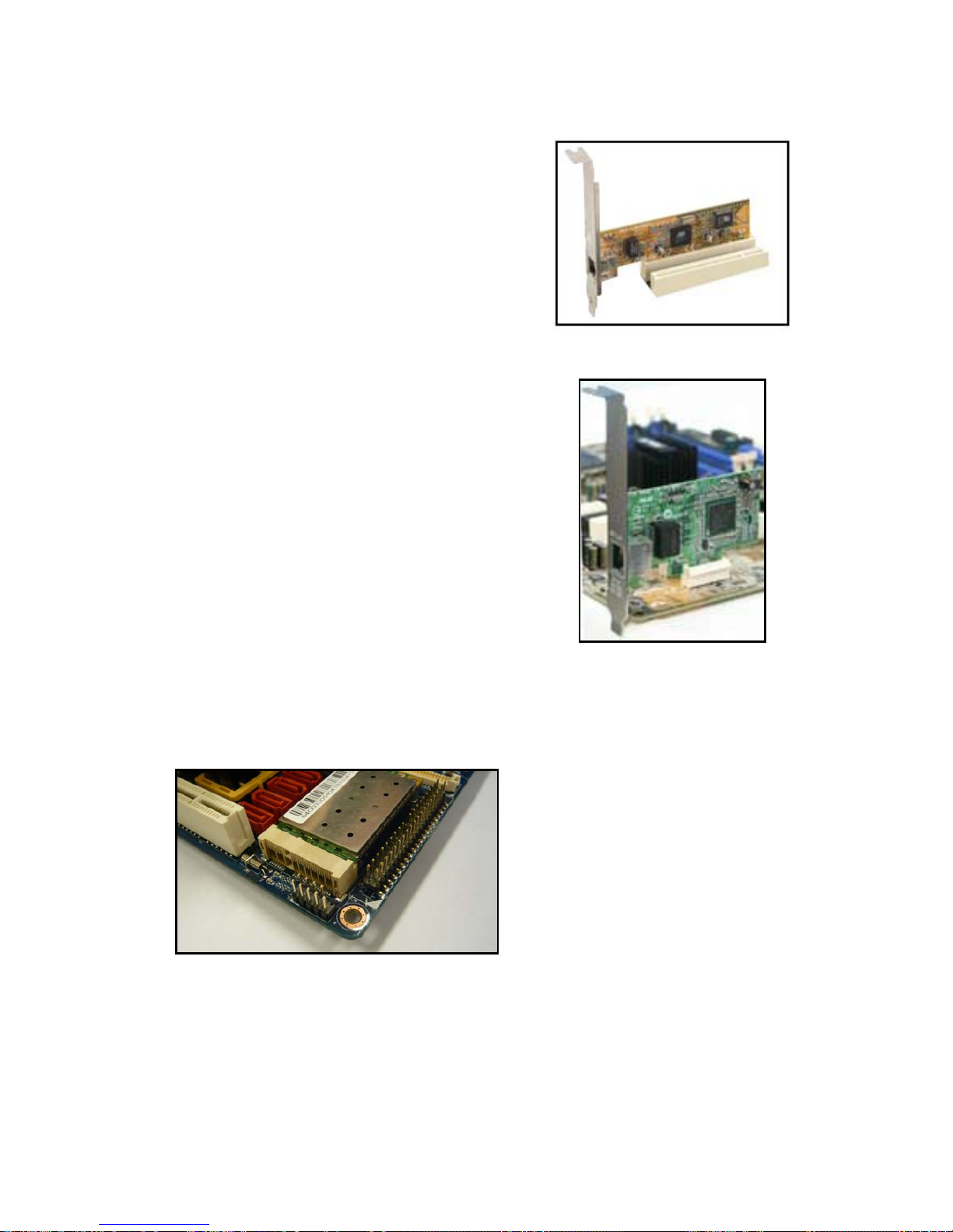
IX45GM has one PCI slots. The PCI slots
support cards such as a LAN card, SCSI card,
USB card, and other cards that comply with PCI
specifications. The figure shows a LAN card
installed on a PCI slot.
1.6.5 PCI Express x1
This motherboard supports PCI Express x1
network cards, SCSI cards and other cards that
comply with the PCI Express specifications. The
figure shows the type of network card that can
be installed on the PCI Express x1 slot.
1.6.6 1.6.6 Mini PCI Express x 1
This motherboard supports Mini PCI Express
wireless LAN, and TV tuner device.
Page 31
User’s Manual
IX45GM
31
1.7 Jumpers
1.7.1 Clear CMOS (CLRTC1)
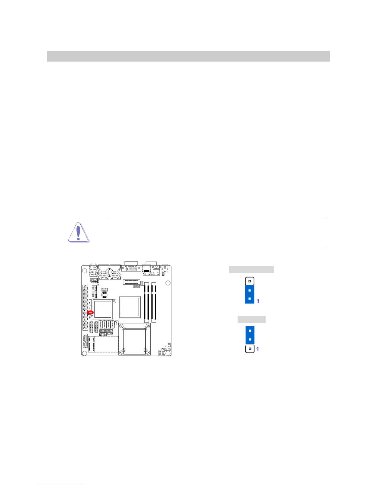
This jumper allows you to clear the Real Time Clock (RTC) RAM in CMOS. You can clear
the CMOS memory of date, time, and system setup parameters by erasing the CMOS RTC
RAM data. The onboard button cell battery powers the RAM data in CMOS, which include
system setup information such as system passwords. To erase the RTC RAM:
1. Turn OFF the computer and unplug the power cord.
2. Remove the onboard battery.
3. Move the jumper cap from pins 1-2 (default) to pins 2-3. Keep the cap on pins 2-3 for
about 5~10 seconds, then move the cap back to pins 1-2.
4. Re-install the battery.
5. Plug the power cord and turn ON the computer.
6. Hold down the <Del> key during the boot process and enter BIOS setup to re-enter
data.
Except when clearing the CMOS, never remove the cap on CLRTC
jumper default position. Removing the cap will cause system boot
failure!
Normal (Default)
Clear RTC
Page 32
IX45GM
32
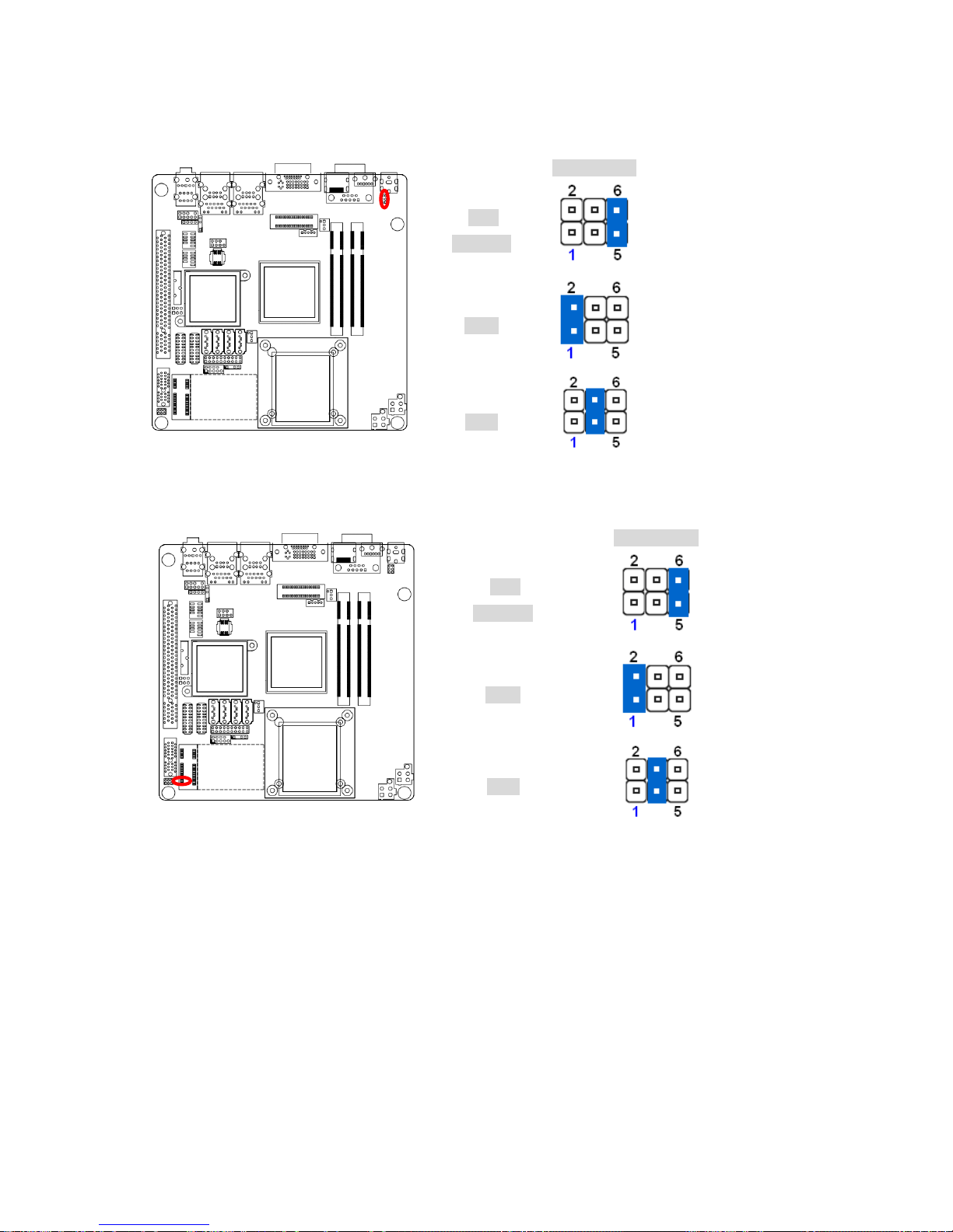
1.7.2 COM1 RI/+5V/+12V Selection (JCOMPWR3)
JCOMPWR3
+5V
(Default)
+
+12V
+
Ring
+
1.7.3 COM2 RI/+5V/+12V Selection (JCOMPWR2)
JCOMPWR2
+5V
(Default)
+
+12V
+
Ring
+
Page 33
User’s Manual
IX45GM
33
1.8 Connectors
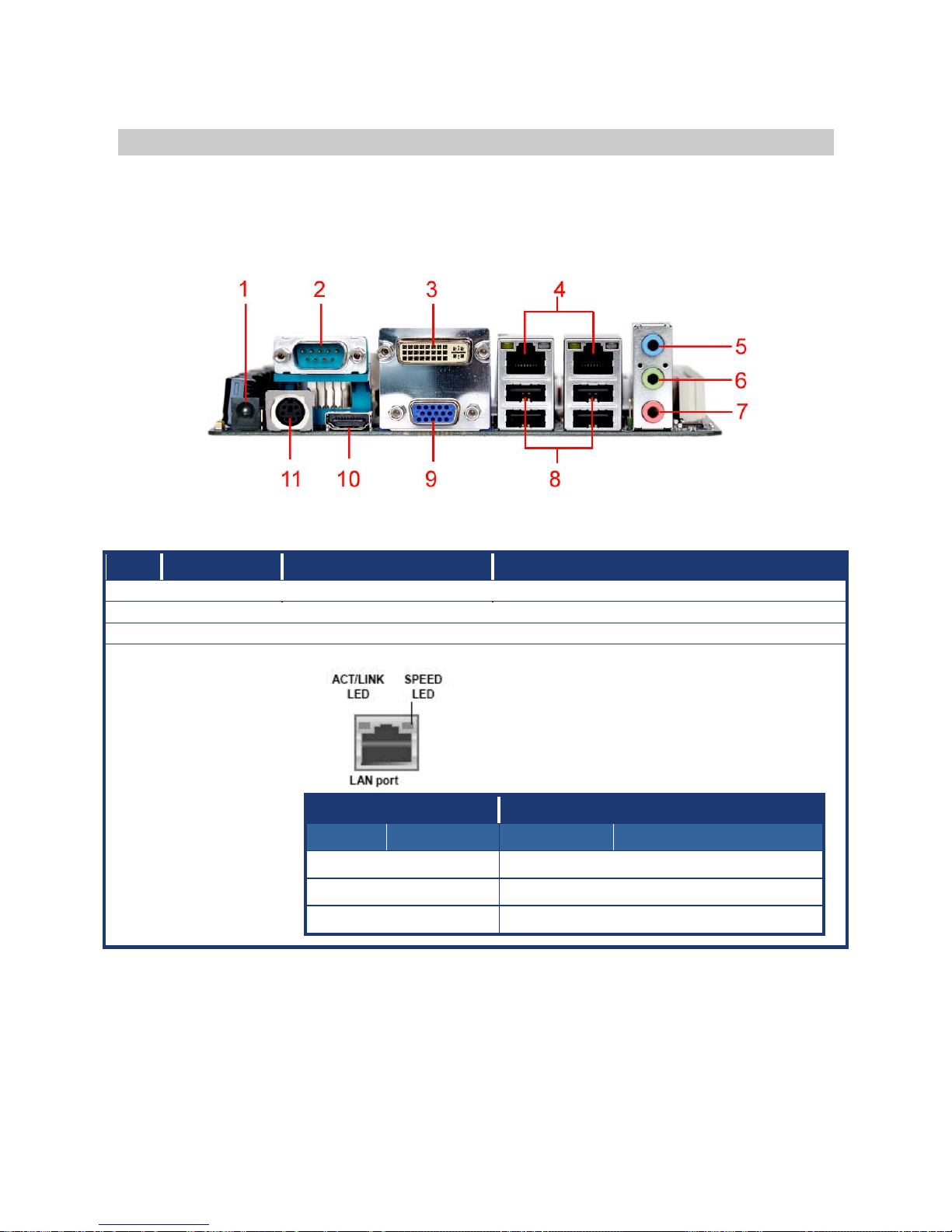
1.8.1 Rear Panel Connectors
No Label Function Description
1 DC_IN1 DC Power In
2 COM1 Serial port connector D-sub 9-pin, male
3 VGA_DVI-D1 DVI port Digital Visual Interface connector
4 LAN_USB1,
LAN_USB2
LAN (RJ-45) connector This port allows Gigabit connection to a
Local Area Network (LAN) through a
network hub. Refer to the table below for
the LAN port LED indications. The optional
10/100/1000 Mbps LAN controller allows
10/100/1000 Mbps connection to a Local
Area Network (LAN) through a network hub.
ACT / LINK LED SPEED LED
Status Description Status Description
OFF No link OFF 10Mbps connection
Orange Linked ORANGE 100Mbps connection
Blinking Data activity GREEN 1Gbps connection
Page 34
IX45GM
34
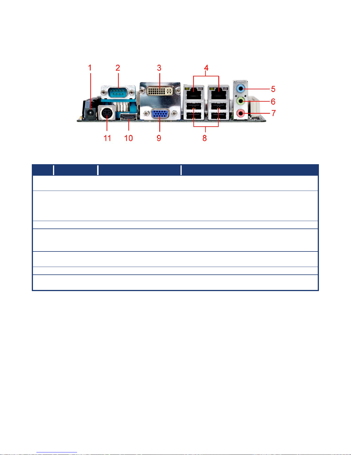
No Label Function Description
5 AUDIO1 Line-In port (Light Blue). This port connects a tape, CD, DVD player, or
other audio sources.
6 AUDIO1 Line-Out port (Lime) This port connects a headphone or a speaker.
In 4-channel, 6-channel, and 8-channel
configuration, the function of this port
becomes Front Speaker Out.
7 AUDIO1 Microphone port (Pink) This port connects a microphone.
8 USB1, USB2 USB 2.0 connector
These four 4-pin Universal Serial Bus (USB)
ports are available for connecting USB 2.0
devices.
9 VGA_DVI-D1 VGA port D-sub15-pin VGA port connects to a VGA
monitor.
10 HDMI1 HDMI connector High Definition Media Interface 19P connector
11 KBMS1 PS/2 Keyboard/Mouse
connector
The standard PS/2 DIN connector is for a
PS/2 Keyboard or mouse.
Page 35
User’s Manual
IX45GM
35
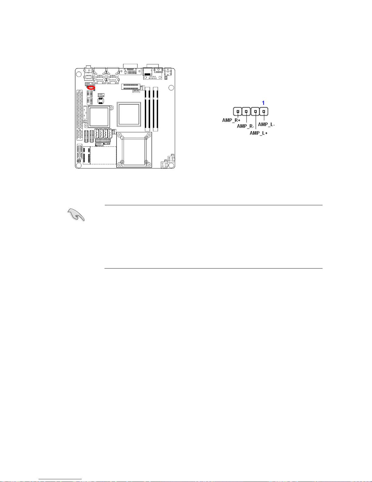
1.8.2 Amplifier Connector (JAMP1)
Important notes on the Motherboard Power Requirements
z Make sure that your ATX 12V power supply can provide 8A on
the +12V lead and at least 1A on the +5-volt standby lead
(+5VSB). The minimum recommended wattage is 230W, or
300W for a fully configured system. The system can become
unstable and might experience difficulty powering up if the power
supply is inadequate.
z You must install a PSU with a higher power rating if you intend to
install additional devices.
Page 36
IX45GM
36
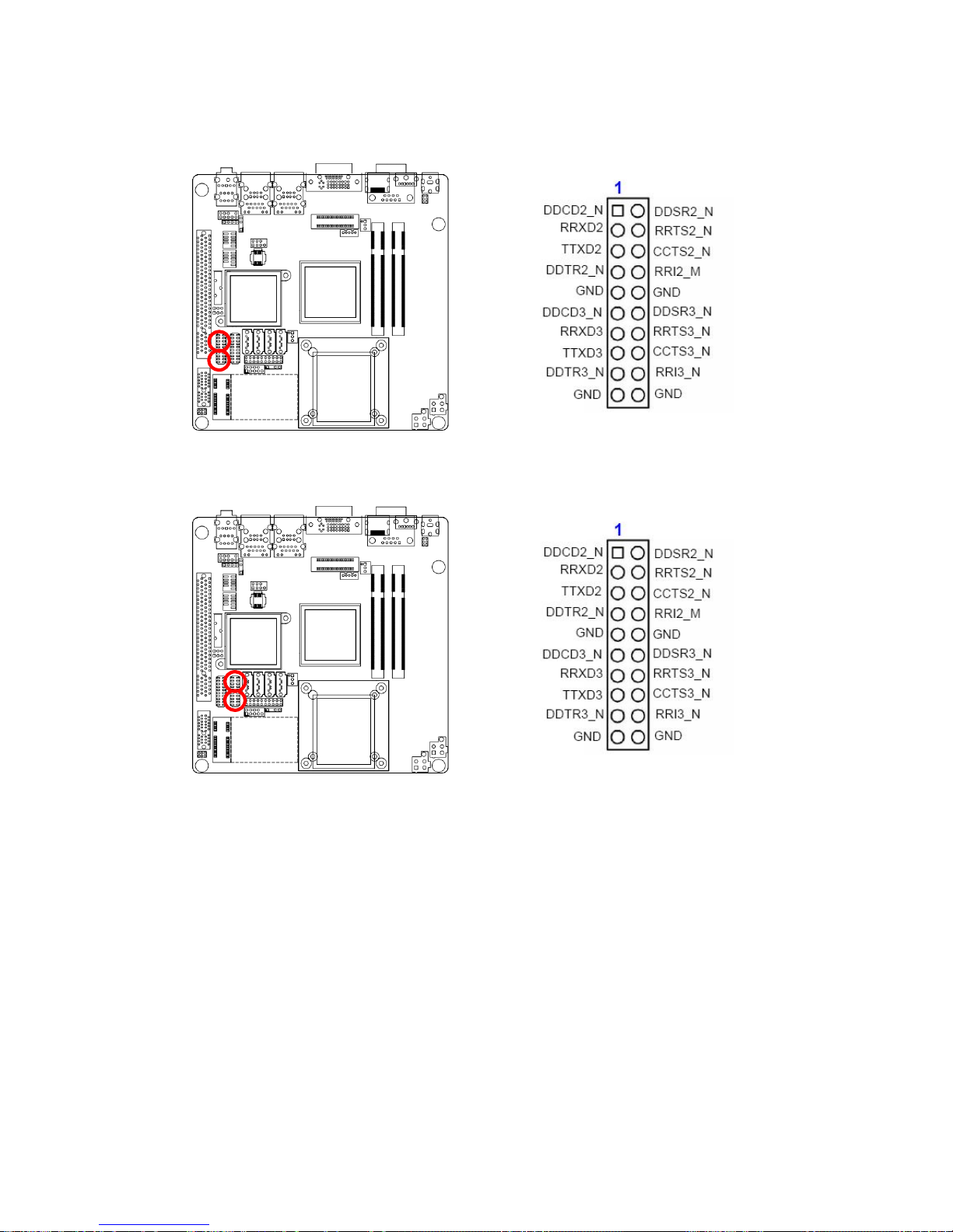
1.8.3 Serial Port 2-3 Connector (COM2, COM3)
1.8.4 Serial Port 4-5 Connector (COM4,COM5)
Page 37
User’s Manual
IX45GM
37
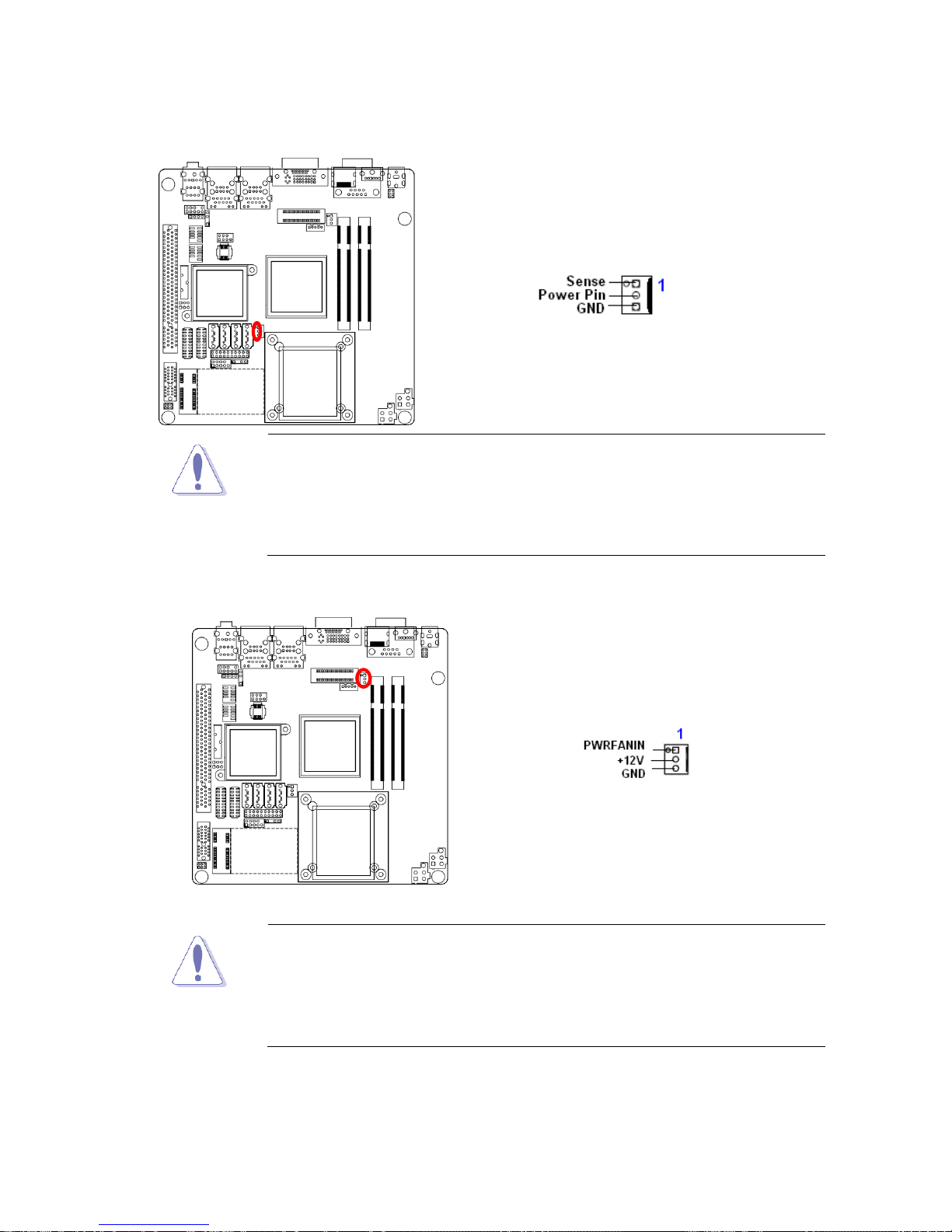
1.8.5 CPU Fan Connector (CPU_FAN1)
z Do not forget to connect the fan cables to the fan connectors.
Insufficient air flow inside the system may damage the
motherboard components, and hardware monitoring errors can
occur if you fail to plug this connector.
z These are not jumpers! DO NOT place jumper caps on the fan
connectors.
1.8.6 System Fan Connector (SYS_FAN1)
z Do not forget to connect the fan cables to the fan connectors.
Insufficient air flow inside the system may damage the
motherboard components, and hardware monitoring errors can
occur if you fail to plug this connector.
z These are not jumpers! DO NOT place jumper caps on the fan
connectors.
Page 38
IX45GM
38
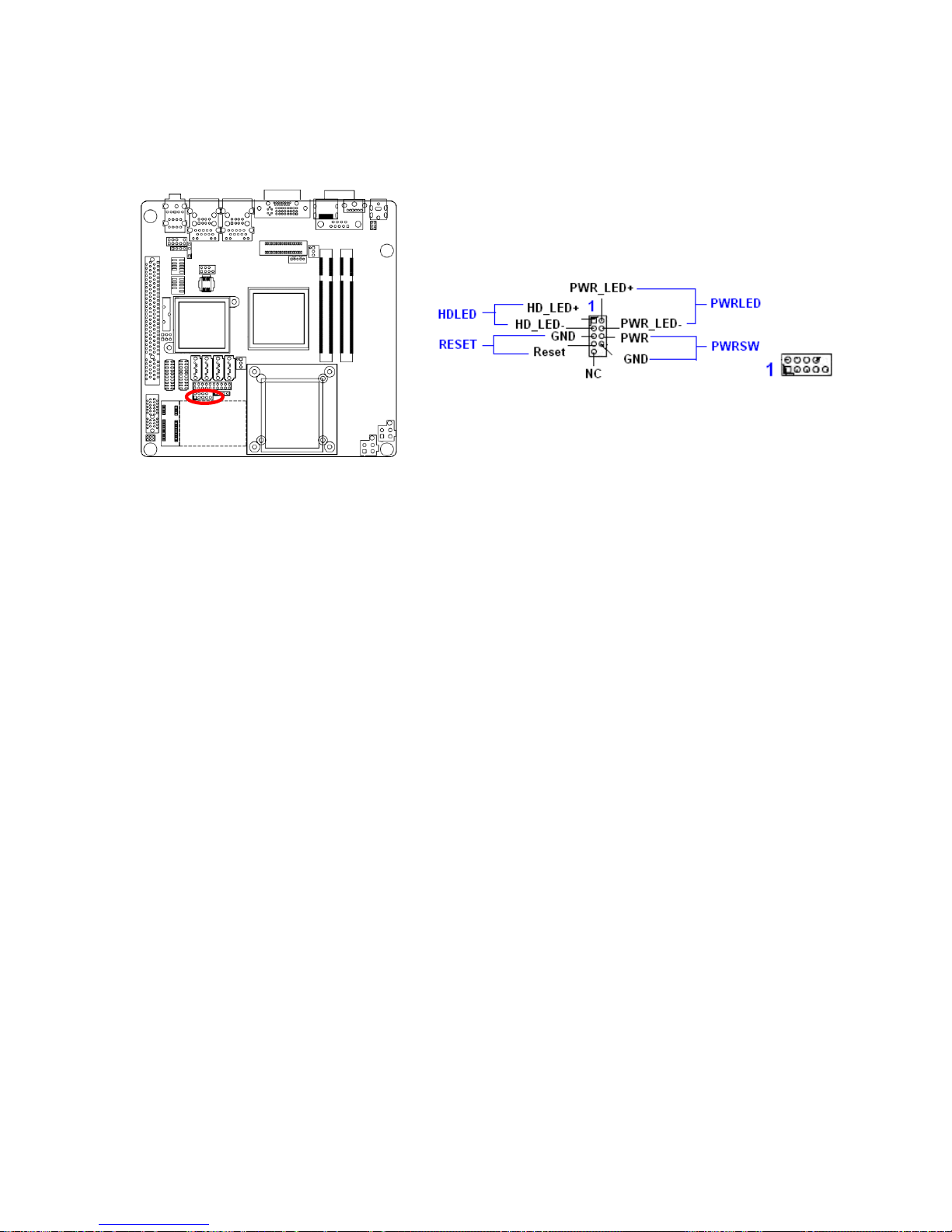
1.8.7 System Panel Connector (FPIO1)
This connector supports several chassis-mounted functions.
z System Power LED (2-pin PWRLED)
This 2-pin connector is for the system power LED. Connect the chassis power LED
cable to this connector. The system power LED lights up when you turn on the system
power, and blinks when the system is in sleep mode.
z ATX Power Button/Soft-off Button (2-pin PWRSW)
This connector is for the system power button. Pressing the power button turns the
system on or puts the system in sleep or soft-off mode depending on the BIOS settings.
Pressing the power switch for more than four seconds while the system is ON turns the
system OFF.
z Hard Disk Drive Activity LED (2-pin HDLED)
This 2-pin connector is for the HDD Activity LED. Connect the HDD Activity LED cable
to this connector. The IDE LED lights up or flashes when data is read from or written to
the HDD.
z Reset Button (2-pin RESET)
This 2-pin connector is for the chassis-mounted reset button for system reboot without
turning off the system power.
Page 39
User’s Manual
IX45GM
39
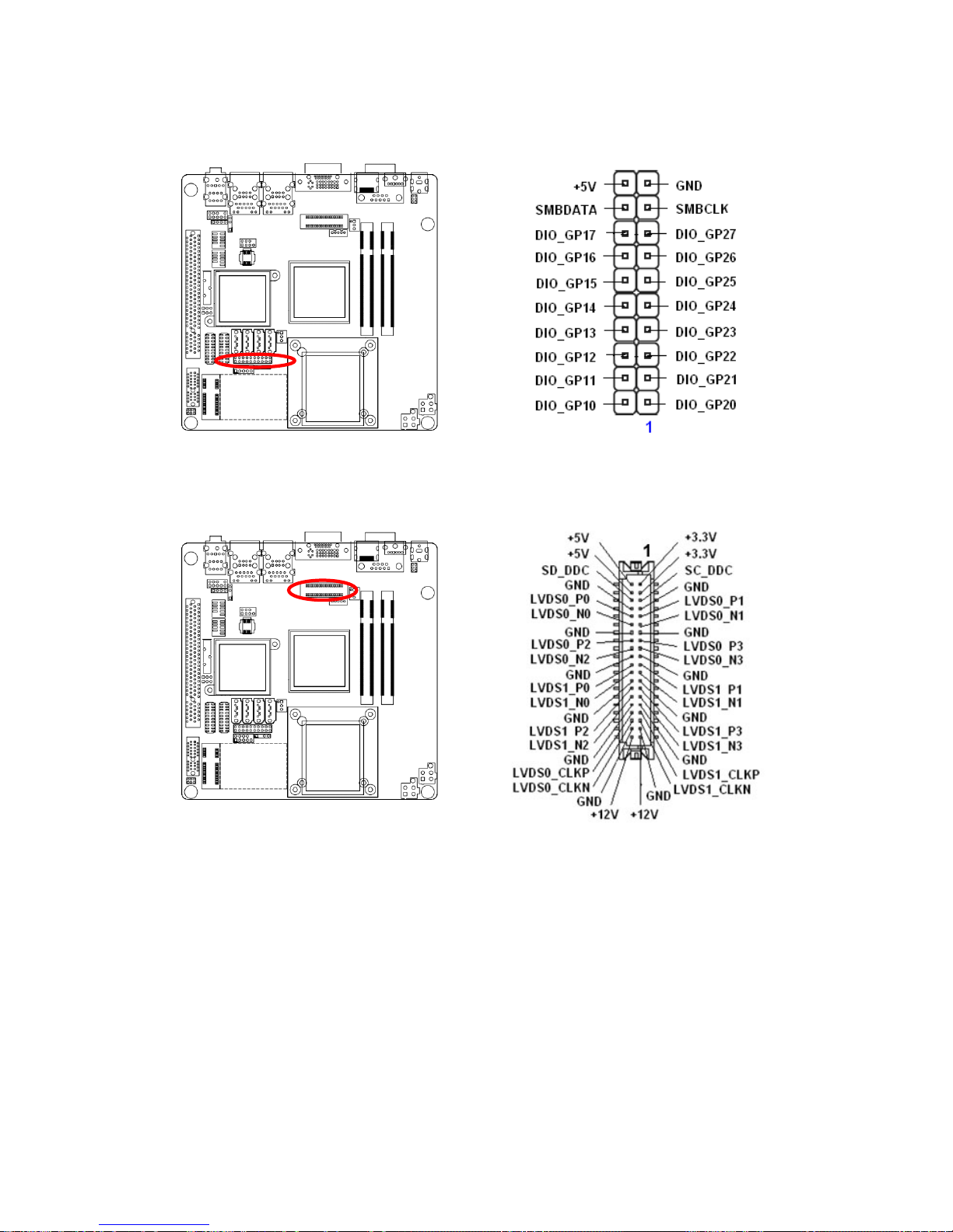
1.8.8 Digital I/O Connector
1.8.9 LVDS Connector (JLVDS1)
Page 40
IX45GM
40
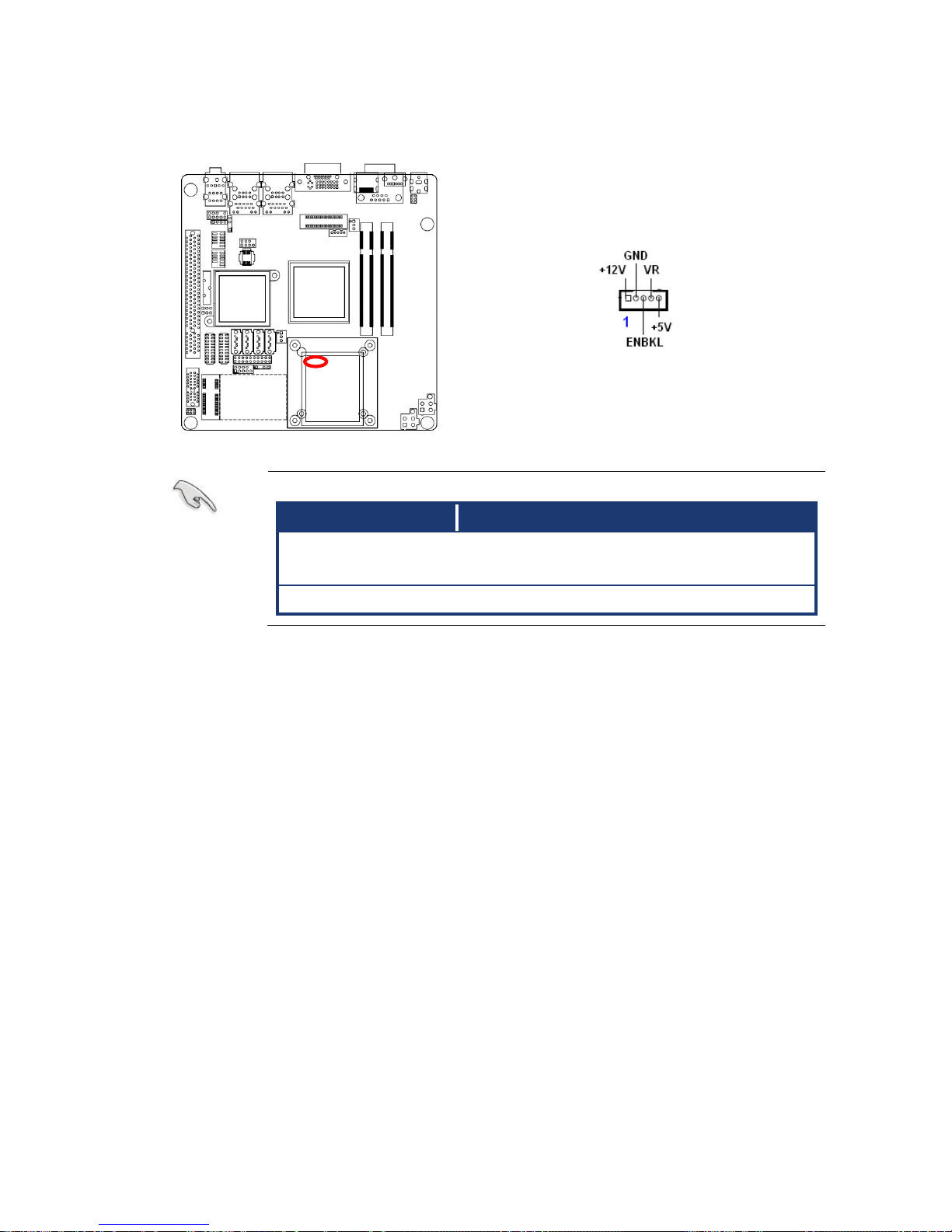
1.8.10 LCD Inverter Connector (JBKL1)
z Signal Description
Signal Signal Description
VR Bright adjust. Vadj=0.75V ~ 4.25V
(Recommended: 4.7KΩ, > 1/16W)
ENBKL LCD backlight ON/OFF control signal
Page 41
User’s Manual
IX45GM
41
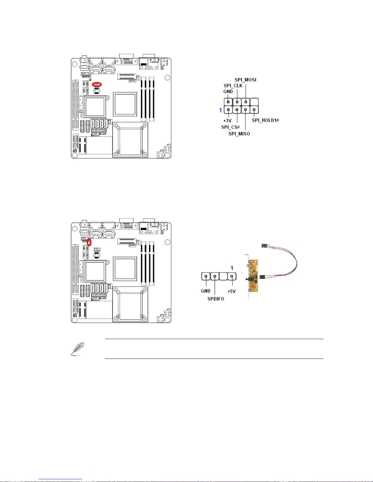
1.8.11 SPI Connector (JSPI1)
1.8.12 Digital Audio Connector (SPDIF_OUT1)
This connector is for an additional Sony/Philips Digital Interface (S/PDIF) port(s). Connect
the S/PDIF module cable to this connector, then install the module to a slot opening at the
back of the system chassis.
The S/PDIF module is purchased separately.
Page 42
IX45GM
42
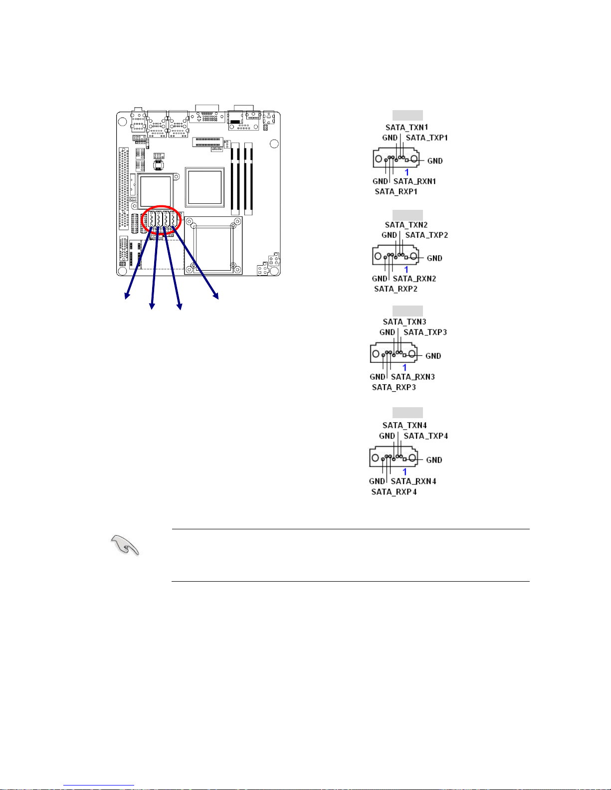
1.8.13 Serial SATA Connector (SATA1, SATA2, SATA3, SATA4)
SATA1
SATA2
SATA3
SATA4
z Install the Windows® 2000 Service Pack 4 or the Windows® XP
Service Pack1 before using Serial ATA.
z When using the connectors in Standard IDE mode, connect the
primary (boot) hard disk drive to the SATA1 connector.
SATA4
SATA2
SATA3
SATA1
Page 43
User’s Manual
IX45GM
43
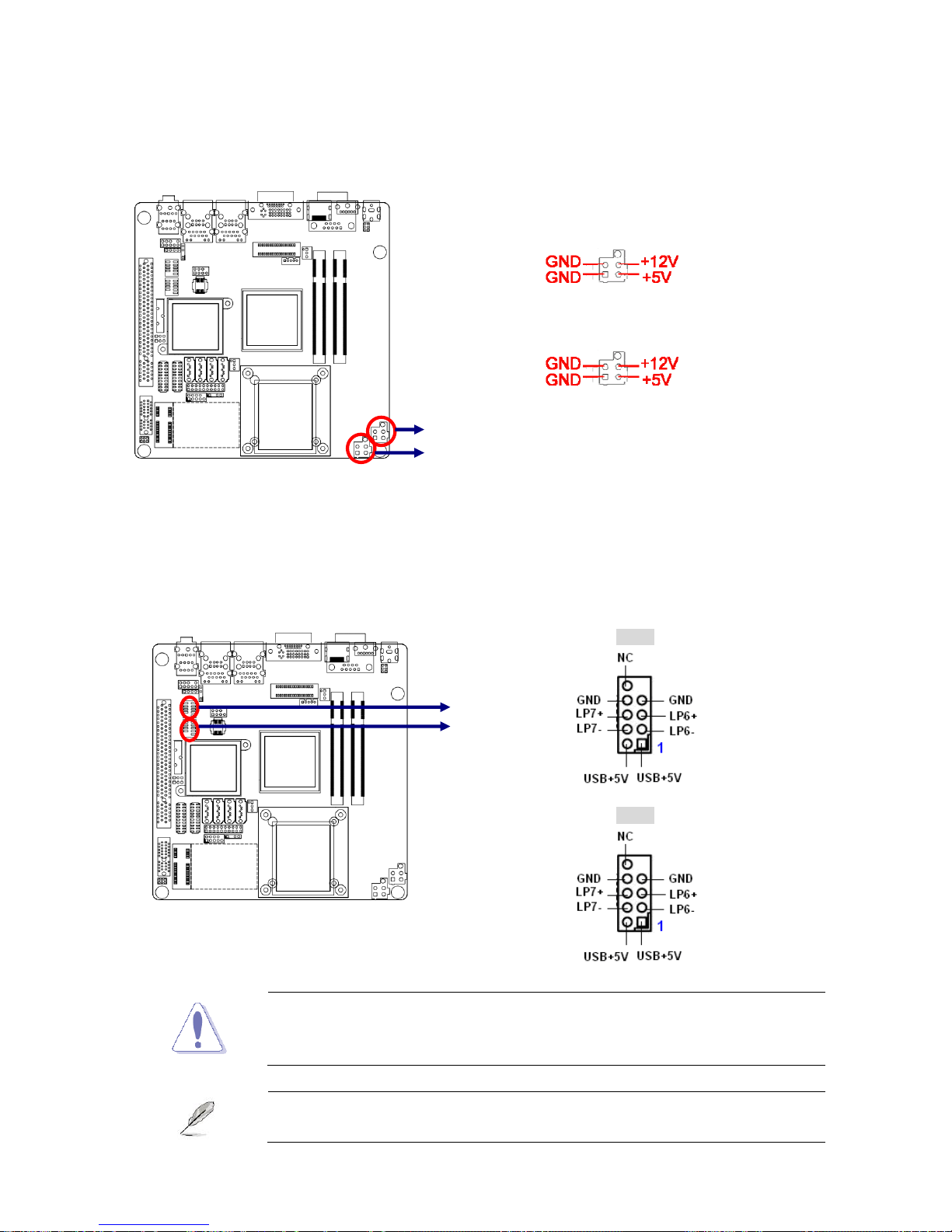
1.8.14 Serial SATA Pow er Connector (SATA_POWER1, SATA_POWER2)
These connectors provide power for SATA devices. Plug SATA Power Cable firmly then
connect SATA power interface on hard drive or optical drive.
1.8.15 USB 2.0 Connector (USB1, USB2)
These connectors are for USB 2.0 ports. Connect the USB/GAME module cable to any of
these connectors, then install the module to a slot opening at the back of the system
chassis. These USB connectors comply with USB 2.0 specification that supports up to 480
Mbps connection speed.
USB1
USB2
Never connect a 1394 cable to the USB connectors. Doing so will
damage the motherboard!
The USB module is purchased separately.
SATA Power1
SATA Power2
USB1
USB2
SATA_POWER1
SATA_POWER2
Page 44

IX45GM
44
2
This chapter tells how to change the
system settings through the BIOS
Setup menus. Detailed descriptions
of the BIOS parameters are also
provided.
BIOS Setup
Page 45

User’s Manual
IX45GM
45
2.1 Managing and updating your BIOS
2.1.1 Creating a bootable floppy disk
1. Do either one of the following to create a bootable floppy disk.
DOS environment
a. Insert a 1.44MB floppy disk into the drive.
b. At the DOS prompt, type format A:/S then press <Enter>.
Windows® XP environment
a. Insert a 1.44 MB floppy disk to the floppy disk drive.
b. Click Start from the Windows® desktop, then select My Computer.
c. Select the 3 1/2 Floppy Drive icon.
d. Click File from the menu, then select Format. A Format 3 1/2 Floppy Disk
window appears.
e. Select Create an MS-DOS startup disk from the format options field, then click
Start.
Windows® 2000 environment
To create a set of boot disks for Windows® 2000:
a. Insert a formatted, high density 1.44 MB floppy disk into the drive.
b. Insert the Windows® 2000 CD to the optical drive.
c. Click Start, then select Run. d. From the Open field, type
D:\bootdisk\makeboot a: assuming that D: is your optical drive.
d. Press <Enter>, then follow screen instructions to continue.
2. Copy the original or the latest motherboard BIOS file to the bootable floppy disk.
Page 46
IX45GM
46
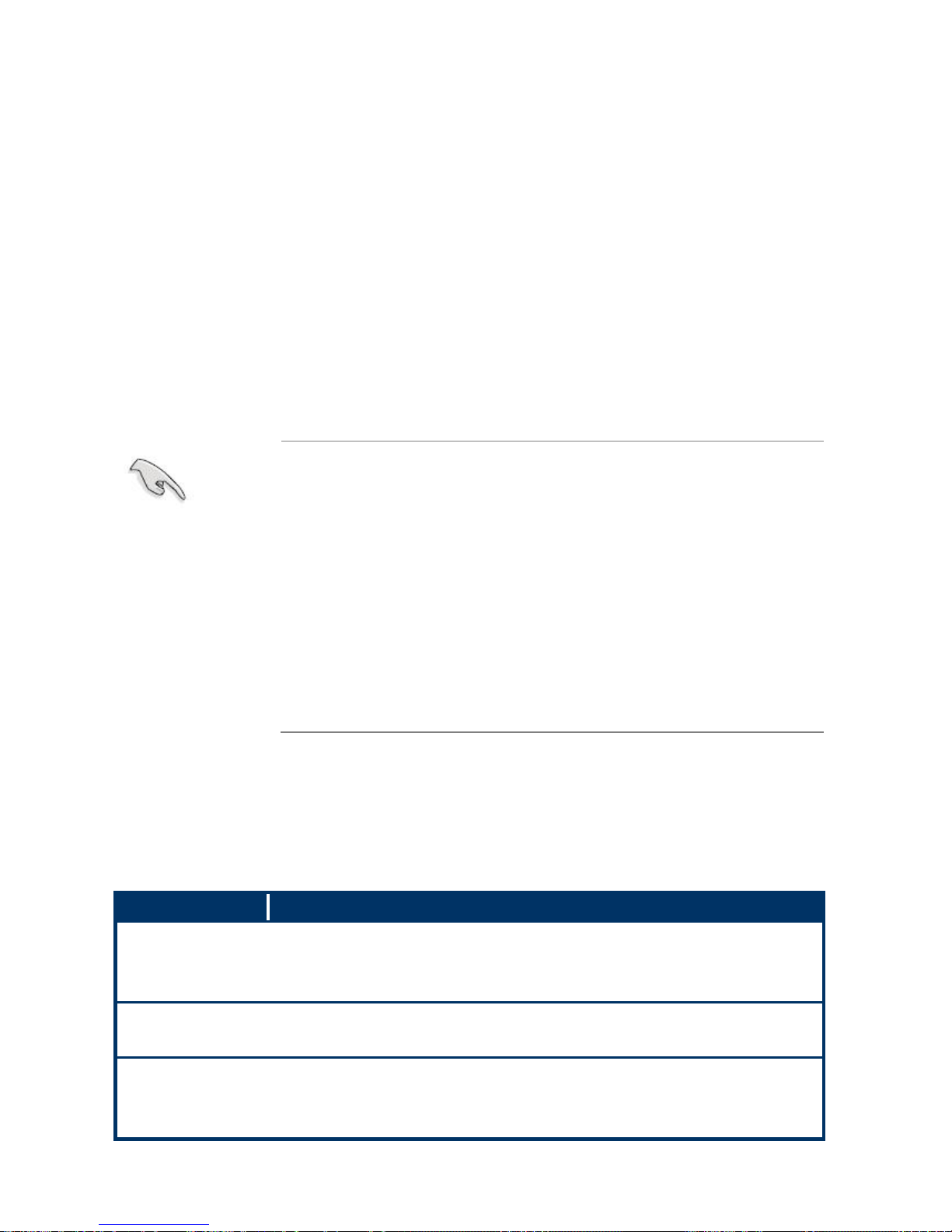
2.2 BIOS setup program
The main BIOS setup menu is the first screen that you can navigate. Each main BIOS
setup menu option is described in this user’s guide.
The Main BIOS setup menu screen has two main frames. The left frame displays all the
options that can be configured. “Grayed-out” options cannot be configured. Options is blue
can be.
The right frame displays the key legend. Above the key legend is an area reserved for a
text message. When an option is selected in the left frame, it is highlighted in white.
Often a text message will accompany it.
z The default BIOS settings for this motherboard apply for most
conditions to ensure optimum performance. If the system
becomes unstable after changing any BIOS settings, load the
default settings to ensure system compatibility and stability.
Select the Load Default Settings item under the Exit Menu.
See section “2.9 Exit Menu.”
z The BIOS setup screens shown in this section are for reference
purposes only, and may not exactly match what you see on
your screen.
z Visit the Advansus website to download the latest BIOS file for
this motherboard.
2.2.1 Legend Box
The BIOS setup/utility uses a key-based navigation system called hot keys. Most of the
BIOS setup utility hot keys can be used at any time during the setup navigation process.
These keys include <F1>, <F10>, <Enter>, <ESC>, <Arrow> keys, and so on.
The keys in the legend bar allow you to navigate through the various setup menus.
Key(s) Function Description
I, J Left/Right The Left and Right <Arrow> keys allow you to select an setup screen.
For example: Main screen, Advanced screen, Chipset screen, and so
on.
K, L Up/Down The Up and Down <Arrow> keys allow you to select an setup item or
sub-screen.
+, - Plus/Minus The Plus and Minus <Arrow> keys allow you to change the field value
of a particular setup item.
For example: Date and Time.
Page 47

User’s Manual
IX45GM
47
Tab The <Tab> key allows you to select setup fields.
F1 The <F1> key allows you to display the General Help screen.
Press the <F1> key to open the General Help screen.
F10 The <F10> key allows you to save any changes you have made and
exit Setup. Press the <F10> key to save your changes.
ESC The <Esc> key allows you to discard any changes you have made
and exit the Setup. Press the <Esc> key to exit the setup without
saving your changes.
Enter The <Enter> key allows you to display or change the setup option
listed for a particular setup item. The <Enter> key can also allow you
to display the setup sub- screens.
2.2.2 List Box
This box appears only in the opening screen. The box displays an initial list of configurable
items in the menu you selected.
2.2.3 Sub-menu
Note that a right pointer symbol (X) appears to the left of certain fields. This pointer
indicates that you can display a sub-menu from this field. A sub-menu contains additional
options for a field parameter. To display a sub-menu, move the highlight to the field and
press <Enter>. The sub-menu appears. Use the legend keys to enter values and move
from field to field within a sub-menu as you would within a menu. Use the <Esc> key to
return to the main menu.
Take some time to familiarize yourself with the legend keys and their corresponding
functions. Practice navigating through the various menus and submenus. While moving
around through the Setup program, note that explanations appear in the Item Specific Help
window located to the right of each menu. This window displays the help text for the
currently highlighted field.
Page 48
IX45GM
48
2.3 Main Setup
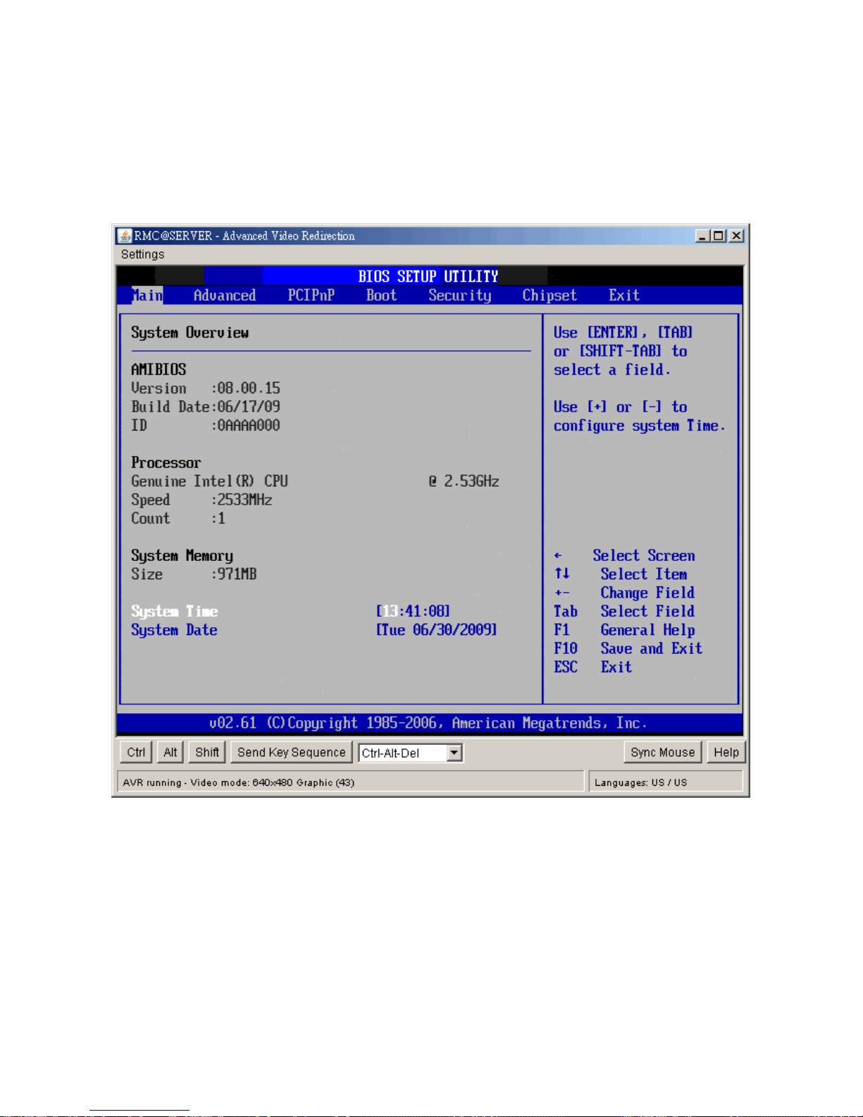
When you first enter the Setup Utility, you will enter the Main setup screen. You can always
return to the Main setup screen by selecting the Main tab. There are two Main Setup
options. They are described in this section. The Main BIOS Setup screen is shown below.
y System Time/System Date
Use this option to change the system time and date. Highlight System Time or System
Date using the <Arrow> keys. Enter new values through the keyboard. Press the <Tab>
key or the <Arrow> keys to move between fields. The date must be entered in MM/DD/YY
format. The time is entered in HH:MM:SS format.
Note: The time is in 24-hour format. For example, 5:30 A.M. appears as 05:30:00, and
5:30P.M. as 17:30:00.
Page 49
User’s Manual
IX45GM
49
2.4 Advanced BIOS Setup
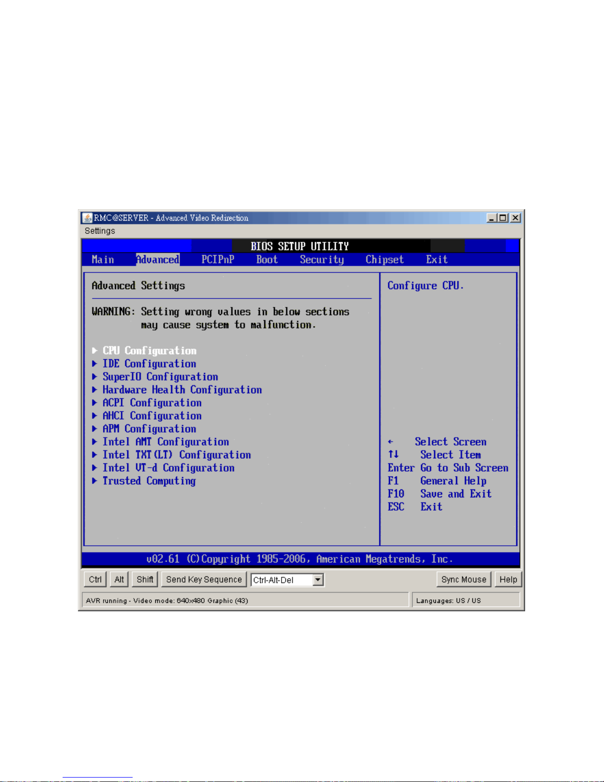
Select the Advanced tab from the setup screen to enter the Advanced BIOS Setup screen.
You can select any of the items in the left frame of the screen, such as SuperIO
Configuration, to go to the sub menu for that item. You can display an Advanced BIOS
Setup option by highlighting it using the <Arrow> keys. All Advanced BIOS Setup options
are described in this section. The Advanced BIOS Setup screen is shown below.
The sub menus are described on the following pages.
CPU Configuration Setting
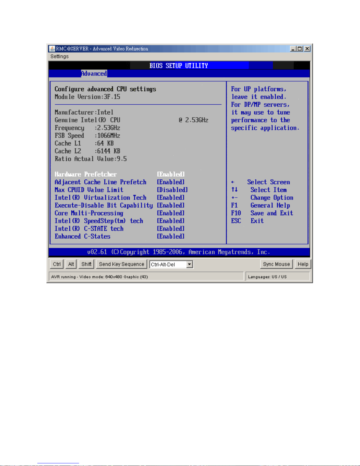
You can use this screen to select options for the CPU Configuration Settings. Use the up
and down <Arrow> keys to select an item. Use the <Plus> and <Minus> keys to change the
value of the selected option. A description of the selected item appears on the right side of
the screen. The settings are described on the following pages.
Page 50
IX45GM
50
y Hardware Prefetcher
The choices of Hardware Prefetcher which prefetchs data from memory to L2 cache are
Disabled, and Enabled.
y Adjacent Cache Line Prefetch
The choices of Adjacement Cache Line Prefetch which automatically fetches an extra
64-byte cache line are Enabled, Disabled.
y Max CPUID Value Limit
The choices of Max CPUID Value Limit are Disabled, and Enabled.
y Intel® Virtualization Tech
The choices of Intel® Virtualization Tech are Enabled, Disabled.
Page 51

User’s Manual
IX45GM
51
y Execute-Disable Bit Capability
The choices of Execute-Disable Bit Capability are Enabled, Disabled.
y Core Multi-Processing
The item is to enable or disable the Core Multi-processing function.
y Intel® SpeedStep™ tech
The choices of Execute-Disable Bit Capability are Enabled, Disabled.
y Intel® C-State tech
The choices of Execute-Disable Bit Capability are Enabled, Disabled.
y Enhanced C-States
The choices of Execute-Disable Bit Capability are Enabled, Disabled.
Page 52
IX45GM
52
IDE Configuration Setting
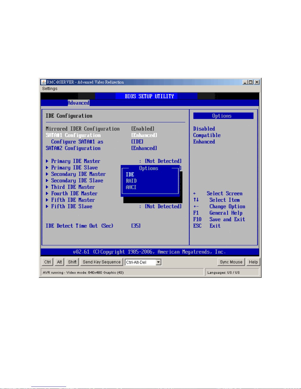
You can use this screen to select options for the IDE Configuration Settings. Use the up
and down <Arrow> keys to select an item. Use the <Plus> and <Minus> keys to change the
value of the selected option. A description of the selected item appears on the right side of
the screen. The settings are described on the following pages.
y Mirrored IDER Configuration
The choices of Mirrored IDER configuration are Disabled, and Enabled.
y SATA#1 Configuration
The choices of SATA configuration are Disabled, Compatible, and Enhanced.
y Configure SATA #1 as
This item allows to configure SATA as IDE, RAID, or AHCI.
Page 53

User’s Manual
IX45GM
53
y SATA#2 Configuration
The choices of SATA configuration are Disabled and Enhanced.
y Primary/Secondary IDE Master/Slave, Third/Fourth IDE Master, Fifth IDE
Master/Slave
Select one of the hard disk drives to configure it. Press <Enter> to access its the sub
menu. The options on the sub menu are described in the following sections.
y IDE Detect Time Out (Sec)
Set this option to stop the AMIBIOS from searching for IDE devices within the specified
number of seconds. Basically, this allows you to fine-tune the settings to allow for faster
boot times. Adjust this setting until a suitable timing that can detect all IDE disk drives
attached is found.
The default setting is 35.
Option Description
0 This value is the best setting to use if the onboard IDE controllers are set to a
specific IDE disk drive in the AMIBIOS.
5 Set this value to stop the AMIBIOS from searching the IDE bus for IDE disk
drives in five seconds. A large majority of ultra ATA hard disk drives can be
detected well within five seconds.
10 Set this value to stop the AMIBIOS from searching the IDE bus for IDE disk
drives in 10 seconds.
15 Set this value to stop the AMIBIOS from searching the IDE bus for IDE disk
drives in 15 seconds.
20 Set this value to stop the AMIBIOS from searching the IDE bus for IDE disk
drives in 20 seconds.
25 Set this value to stop the AMIBIOS from searching the IDE bus for IDE disk
drives in 25 seconds.
30 Set this value to stop the AMIBIOS from searching the IDE bus for IDE disk
drives in 30 seconds.
35 35 is the default value. It is the recommended setting when all IDE connectors
are set to AUTO in the AMIBIOS setting.
Note: Different IDE disk drives take longer for the BIOS to locate than others do.
Page 54
IX45GM
54
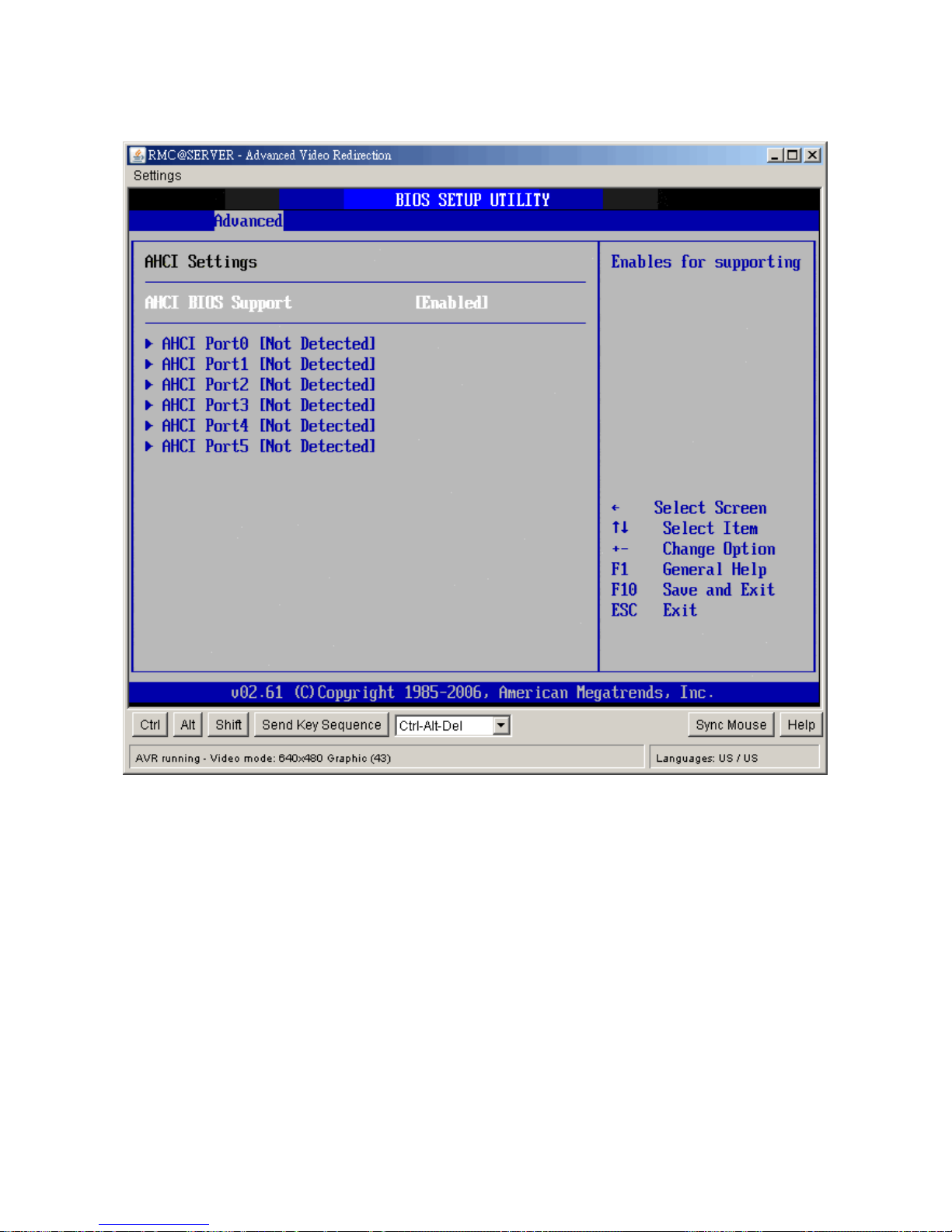
AHCI Configuration
- AHCI BIOS Support
Enables for supporting AHCI BIOS. The choices are Enabled or Disabled.
Page 55
User’s Manual
IX45GM
55
2.4.1 Super I/O Configuration
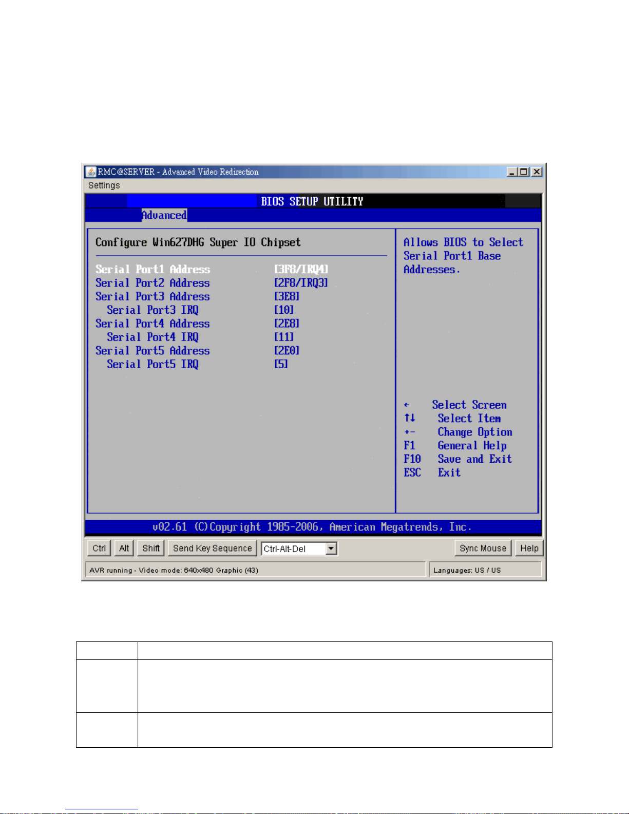
You can use this screen to select options for the Super I/O settings. Use the up and down
<Arrow> keys to select an item. Use the <Plus> and <Minus> keys to change the value of
the selected option. The settings are described on the following pages. The screen is
shown below.
y Serial Port1 Address
This option specifies the base I/O port address and Interrupt Request address of serial port
1. The Optimal setting is 3F8/IRQ4.
Option Description
Disabled Set this value to prevent the serial port from accessing any system resources.
When this option is set to Disabled, the serial port physically becomes
unavailable.
3F8/IRQ4 Set this value to allow the serial port to use 3F8 as its I/O port address and
IRQ4 for the interrupt address. This is the default setting. The majority of serial
Page 56

IX45GM
56
port 1 or COM1 ports on computer systems use IRQ4 and I/O Port 3F8 as the
standard setting. The most common serial device connected to this port is a
mouse. If the system will not use a serial device, it is best to set this port to
Disabled.
y Serial Port2 Address
This option specifies the base I/O port address and Interrupt Request address of serial port
2. The Optimal setting is 2F8/IRQ3.
Option Description
Disabled Set this value to prevent the serial port from accessing any system resources.
When this option is set to Disabled, the serial port physically becomes
unavailable.
2F8/IRQ3 Set this value to allow the serial port to use 2F8 as its I/O port address and IRQ
3 for the interrupt address. This is the default setting. The majority of serial port
2 or COM2 ports on computer systems use IRQ3 and I/O Port 2F8 as the
standard setting. The most common serial device connected to this port is an
external modem. If the system will not use an external modem, set this port to
Disabled.
Note: Most internal modems require the use of the second COM port and use
3F8 as its I/O port address and IRQ 4 for its interrupt address. This requires
that the Serial Port2 Address be set to Disabled or another base I/O port
address and Interrupt Request address.
y Serial Port3 Address
This option specifies the base I/O port address of serial port 3. The Optimal setting is 3E8.
y Serial Port3 IRQ
This option specifies the Interrupt Request address of serial port 3. The Optimal setting is
10.
Option Description
Disabled Set this value to prevent the serial port from accessing any system resources.
When this option is set to Disabled, the serial port physically becomes
unavailable.
3E8/IRQ10 Set this value to allow the serial port to use 3E8 as its I/O port address and
IRQ10 for the interrupt address. This is the default setting. If the system will
not use a serial device, it is best to set this port to Disabled.
y Serial Port4 Address
Page 57

User’s Manual
IX45GM
57
This option specifies the base I/O port address of serial port 4. The Optimal setting is 2E8.
y Serial Port4 IRQ
This option specifies the Interrupt Request address of serial port 4. The Optimal setting is
11.
Option Description
Disabled Set this value to prevent the serial port from accessing any system resources.
When this option is set to Disabled, the serial port physically becomes
unavailable.
2E8/IRQ11 Set this value to allow the serial port to use 2E8 as its I/O port address and
IRQ11 for the interrupt address. This is the default setting. If the system will
not use a serial device, it is best to set this port to Disabled.
y Serial Port5 Address
This option specifies the base I/O port address of serial port 5. The Optimal setting is 2E0.
y Serial Port5 IRQ
This option specifies the Interrupt Request address of serial port 5. The Optimal setting is 5.
Option Description
Disabled Set this value to prevent the serial port from accessing any system resources.
When this option is set to Disabled, the serial port physically becomes
unavailable.
2E0/IRQ5 Set this value to allow the serial port to use 2E0 as its I/O port address and
IRQ5 for the interrupt address. This is the default setting. If the system will not
use a serial device, it is best to set this port to Disabled.
Page 58

IX45GM
58
You can use this screen to select options for the Hardware Health settings. Use the up and
down <Arrow> keys to select an item. Use the <Plus> and <Minus> keys to change the
value of the selected option. The settings are described on the following pages. The screen
is shown below.
y Chassis Intrusion
This item selects the chassis intrusion. The choices are Disabled or Enabled.
y System Temperature
This shows you the current temperature of system.
y CPU Temperature
This shows you the current CPU temperature.
y SYS_FAN Speed
This shows the current System FAN operating speed.
y CPU_FAN Speed
Page 59

User’s Manual
IX45GM
59
This shows the current CPU FAN operating speed.
y Vcore/ 3VCC/ +12V/ +5V/ 5VSB/ 3VSB/ VBAT
This shows the voltage of VCORE, 3VCC, +12V, +5V, 5VSB(V), 3VSB(V) and VBAT(V).
y CPU Smart Fan
The options are Disabled, Silent mode, Optimal mode and Performance mode.
y System Smart Fan
The options are Disabled, Silent mode, Optimal mode and Performance mode.
Page 60
IX45GM
60
2.4.2 ACPI Configuration
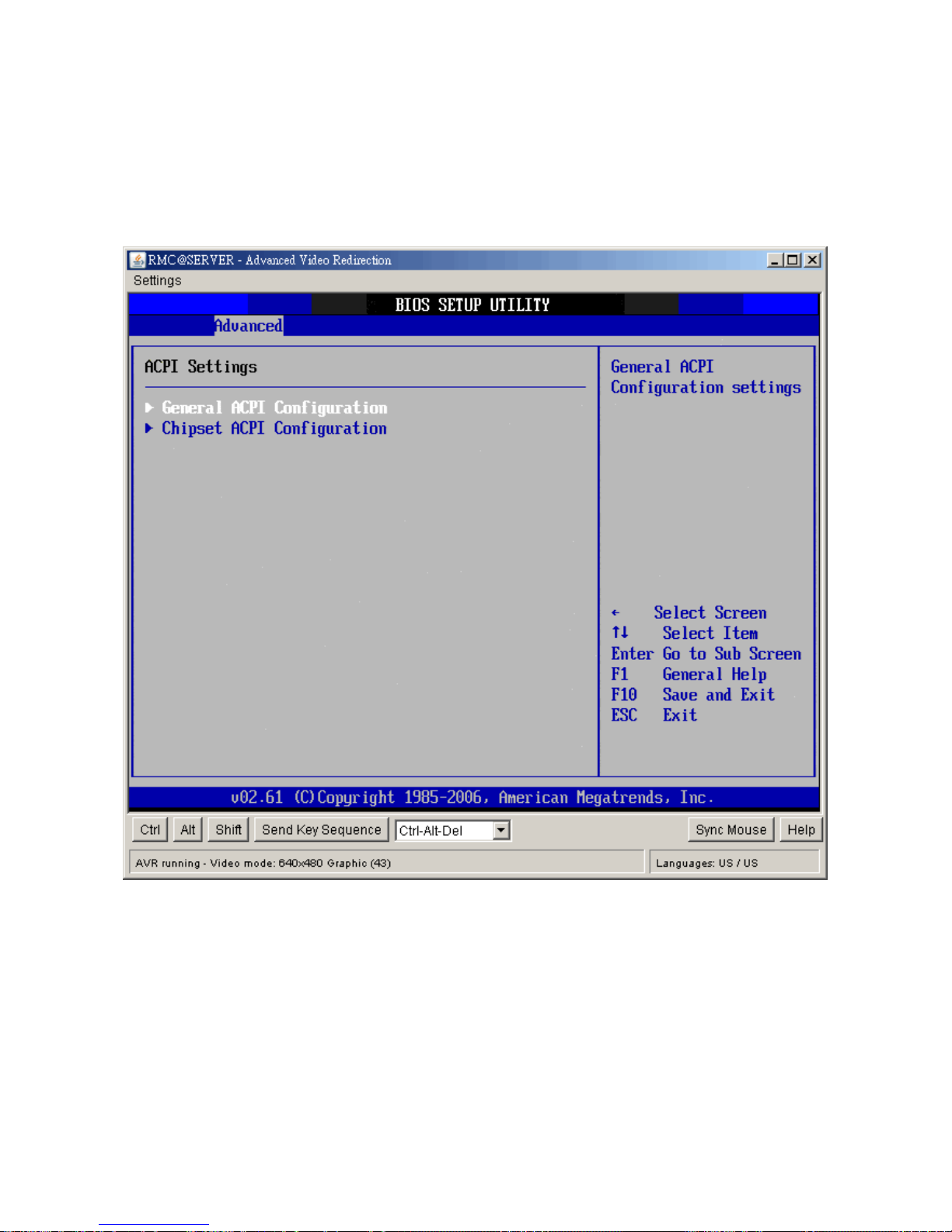
You can use this screen to select options for the ACPI settings. Use the up and down
<Arrow> keys to select an item. Use the <Plus> and <Minus> keys to change the value of
the selected option. The settings are described on the following pages. The screen is
shown below.
y General ACPI Configuration
This item allows you to set general ACPI Configuration.
y Chipset ACPI Configuration
This item allows you to set South Bridge ACPI Configuration.
Page 61
User’s Manual
IX45GM
61
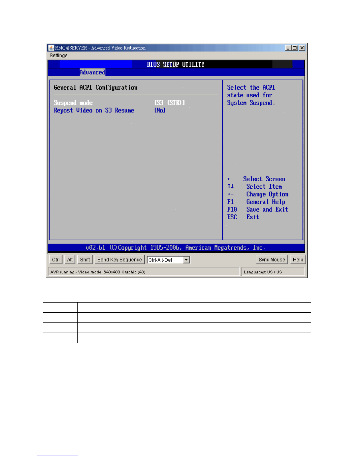
y Suspend mode
The item allows you to select the suspend type under the ACPI operating system.
Option Description
S1 (POS) Power on Suspend
S3 (STR) Suspend to RAM
Auto POS+STR
y Repost Video on S3 Resume
Determines whether to invoke VGA BIOS post on S3/STR resume. The choices are No or
Yes.
Page 62
IX45GM
62
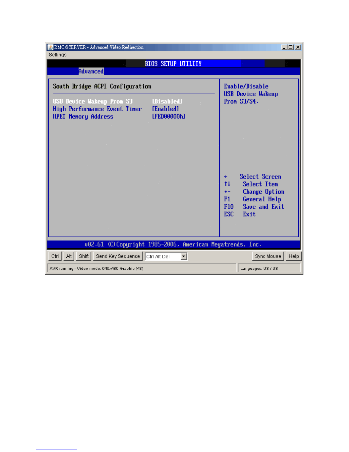
y USB Device Wakeup from S3
This item allows you to enable or disabled the USB resume from S3/S4 status.
y High Performance Event Timer
This item allows you to enable or disable the High Performance Event Timer.
y HPET Memory Address
This item allows you to allot the Event Timer Block Registers Base Address to thememory.
Page 63
User’s Manual
IX45GM
63
2.4.3 AHCI Configuration
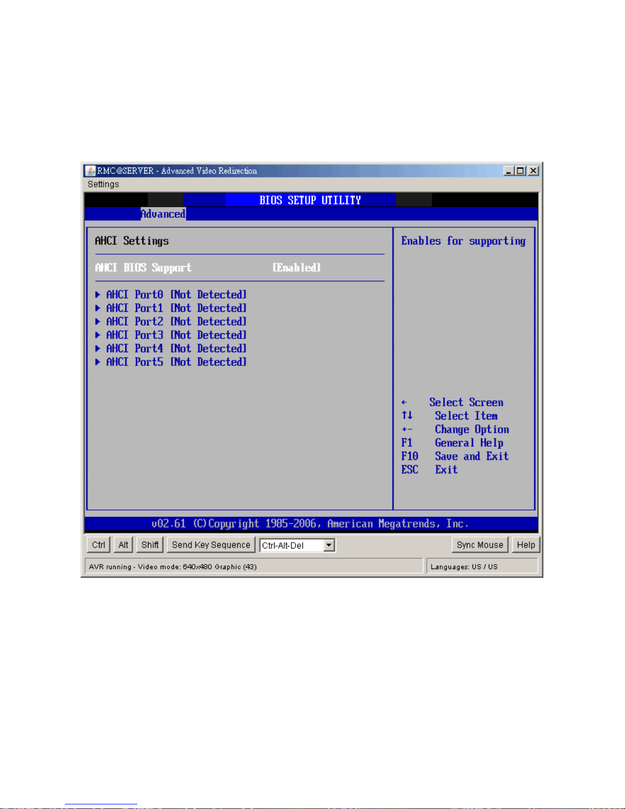
You can use this screen to select options for the AHCI settings. Use the up and down
<Arrow> keys to select an item. Use the <Plus> and <Minus> keys to change the value of
the selected option. The settings are described on the following pages. The screen is
shown below.
y AHCI BIOS Support
This BIOS feature controls the AHCI function of SATA controller. The choice are Enabled
(Default) / Disabled
Page 64
IX45GM
64
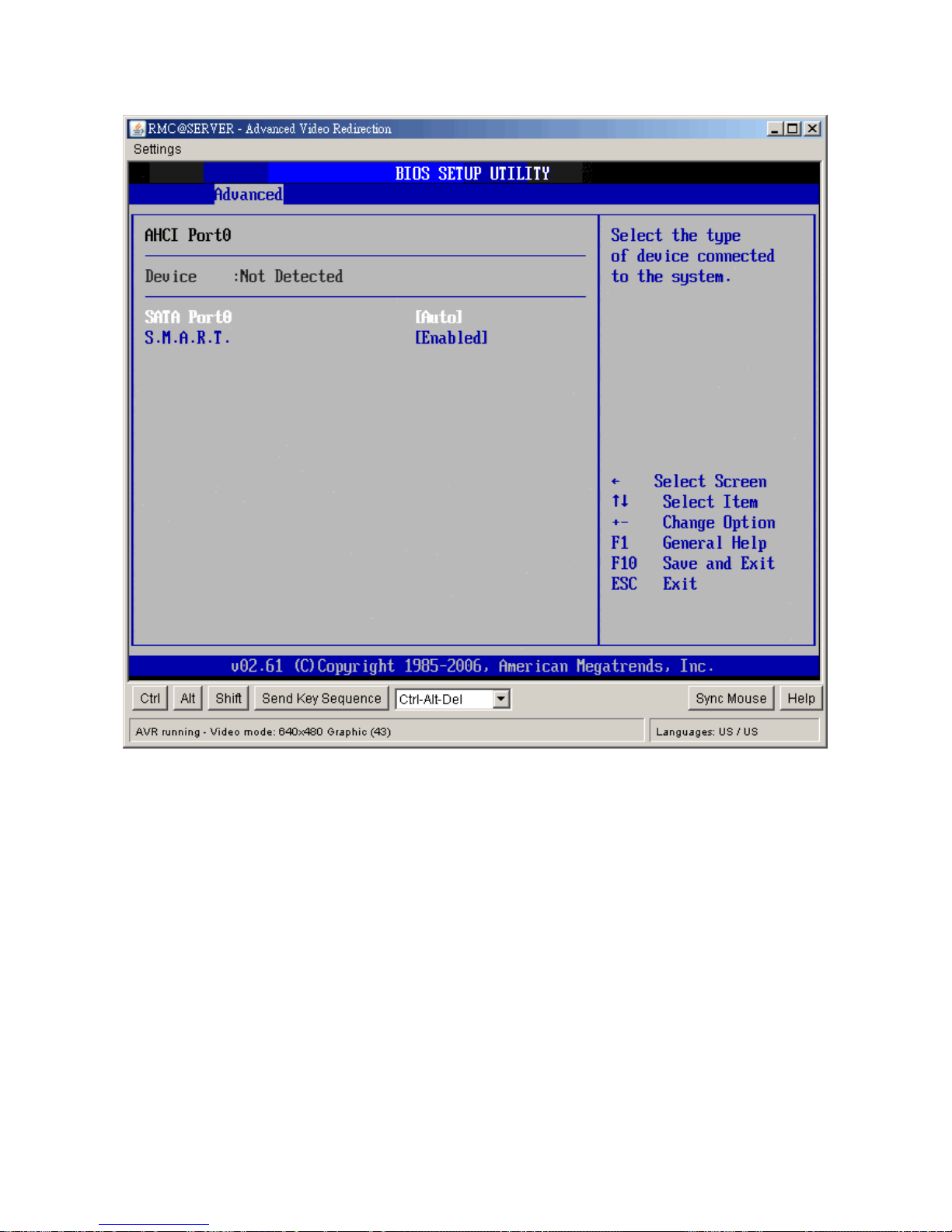
y Device
This area shows the detected connected device.
y SATA Port0/1/2/3/4/5
This item allows you to select the connected device type. Options: Auto (Default)
y S.M.A.R.T.
This item allows you to control the device S.M.A.R.T function. The options are Enabled
(Default) / Disabled
Page 65
User’s Manual
IX45GM
65
2.4.4 APM Configuration
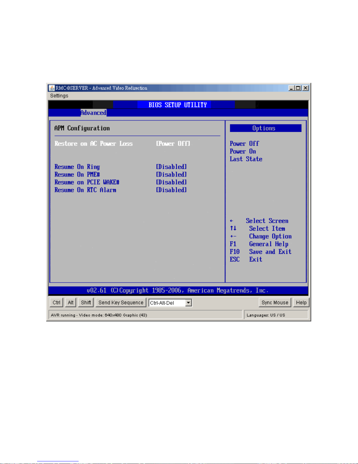
You can use this screen to select options for the APM settings. Use the up and down
<Arrow> keys to select an item. Use the <Plus> and <Minus> keys to change the value of
the selected option. The settings are described on the following pages.
y Restore on AC Power Loss
This item allows you to set AC Power Loss to Power Off, Power On, or Last State.
y Resume On Ring
Disable or Enable RI to generate a wake event.
y Resume On PME#
Disable or Enable PME to generate a wake event.
y Resume On PCIE WAKE#
Disable or Enable PCIE generate a wake event.
y Resume RTC Alarm
Disable or Enable RTC to generate a wake event.
Page 66
IX45GM
66
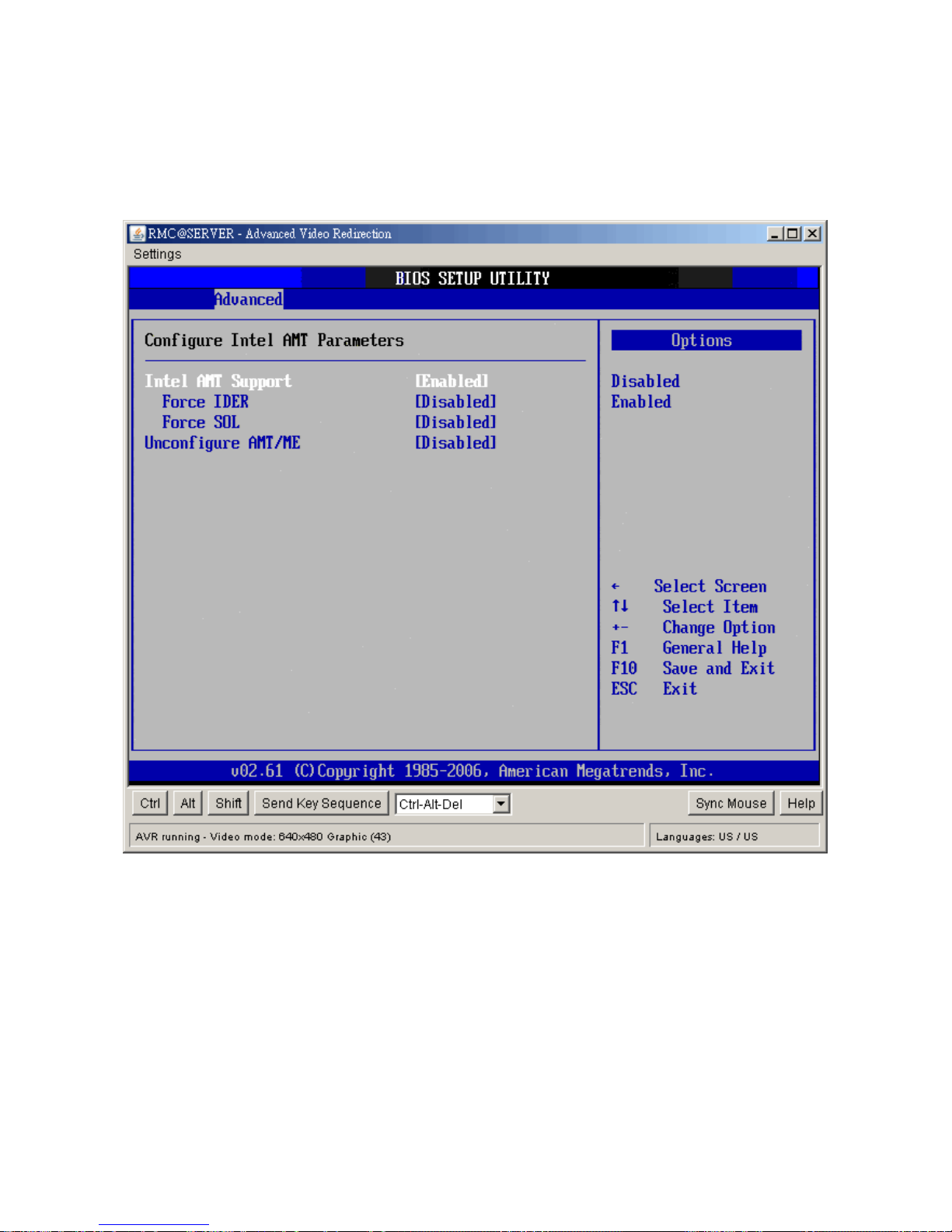
2.4.5 Intel AMT Configuration
You can use this screen to select options for Intel AMT settings. Use the up and down
<Arrow> keys to select an item. Use the <Plus> and <Minus> keys to change the value of
the selected option. The settings are described on the following pages.
z Intel AMT Support
Intel Active Management Technology (AMT) is hardware-based technology for
remotely managing and securing PCs out-of-band. The options are Disabled, Enabled
z Force IDE/Force SOL
SOL/ IDER (Serial Over LAN/ IDE-Redirection) is a protocol defined for Intel
Active Management Technology that allows redirecting the keyboard/text or
floppy disk/CD transfers from a local host to a remote workstation.
z Unconfigure AMT/ME
To finish the unconfiguration of AMT, set this setting to [Enabled] and the BIOS
will unconfigure all of AMT/ME settings and all the passwords are reset.
Page 67
User’s Manual
IX45GM
67
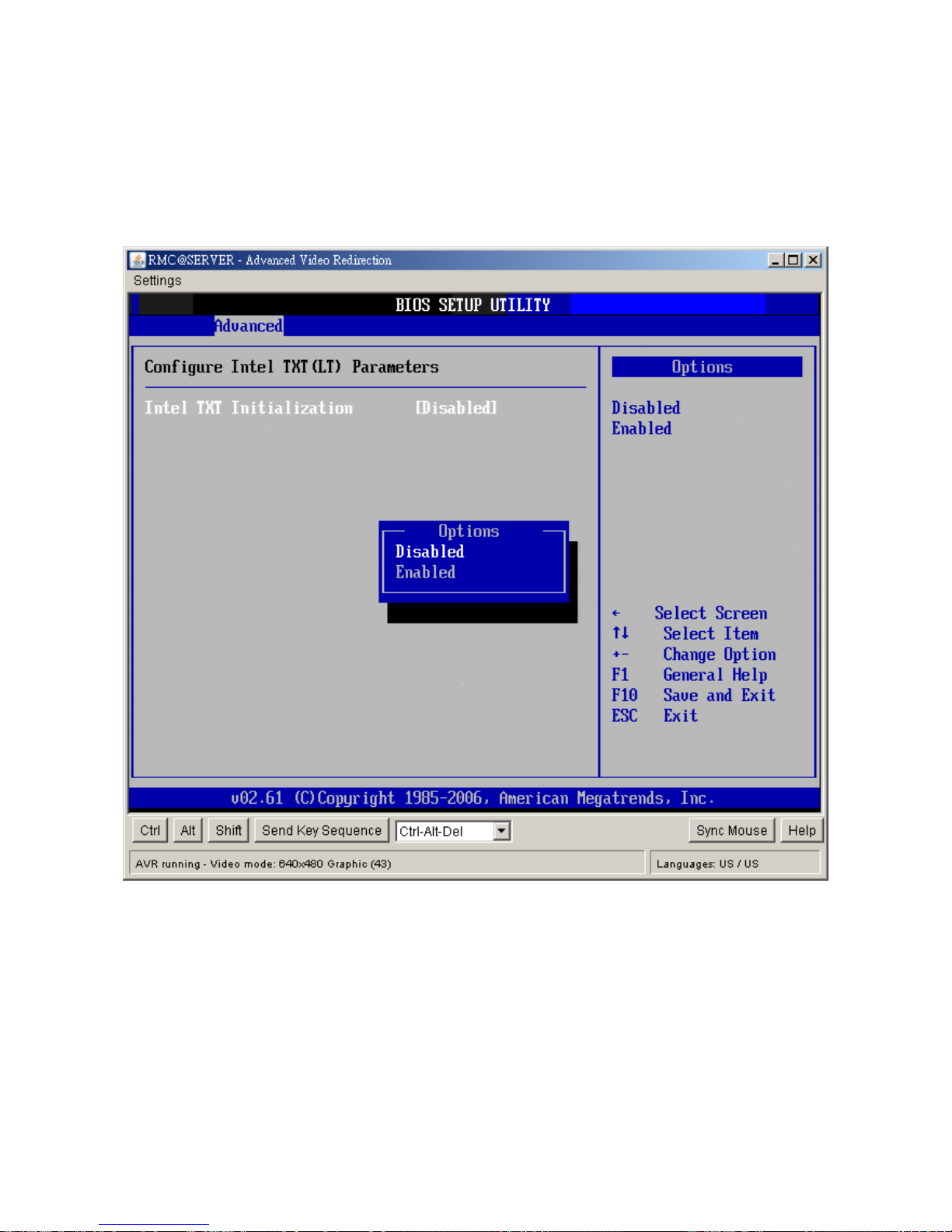
2.4.6 Intel TXT (LT) Configuration
You can use this screen to select options for the Intel TXT (LT) settings. Use the up and
down <Arrow> keys to select an item. Use the <Plus> and <Minus> keys to change the
value of the selected option. The settings are described on the following pages. The screen
is shown below.
y Intel TXT Initialization
The Choices are enabled or disabled the Intel TXT initialization.
Page 68
IX45GM
68
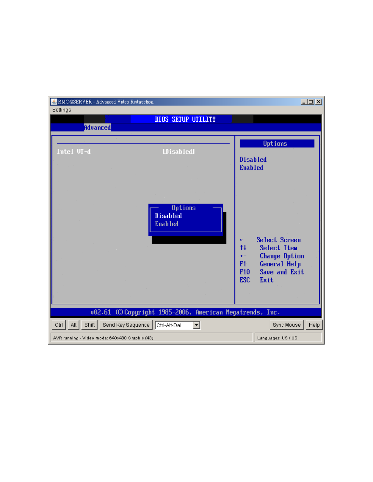
2.4.7 Intel VT-d Configuration
You can use this screen to select options for the Intel VT-d settings. Use the up and down
<Arrow> keys to select an item. Use the <Plus> and <Minus> keys to change the value of
the selected option. The settings are described on the following pages. The screen is
shown below.
y Intel VT-d
The Choices are enabled or disabled the Intel VT-d.
Page 69
User’s Manual
IX45GM
69
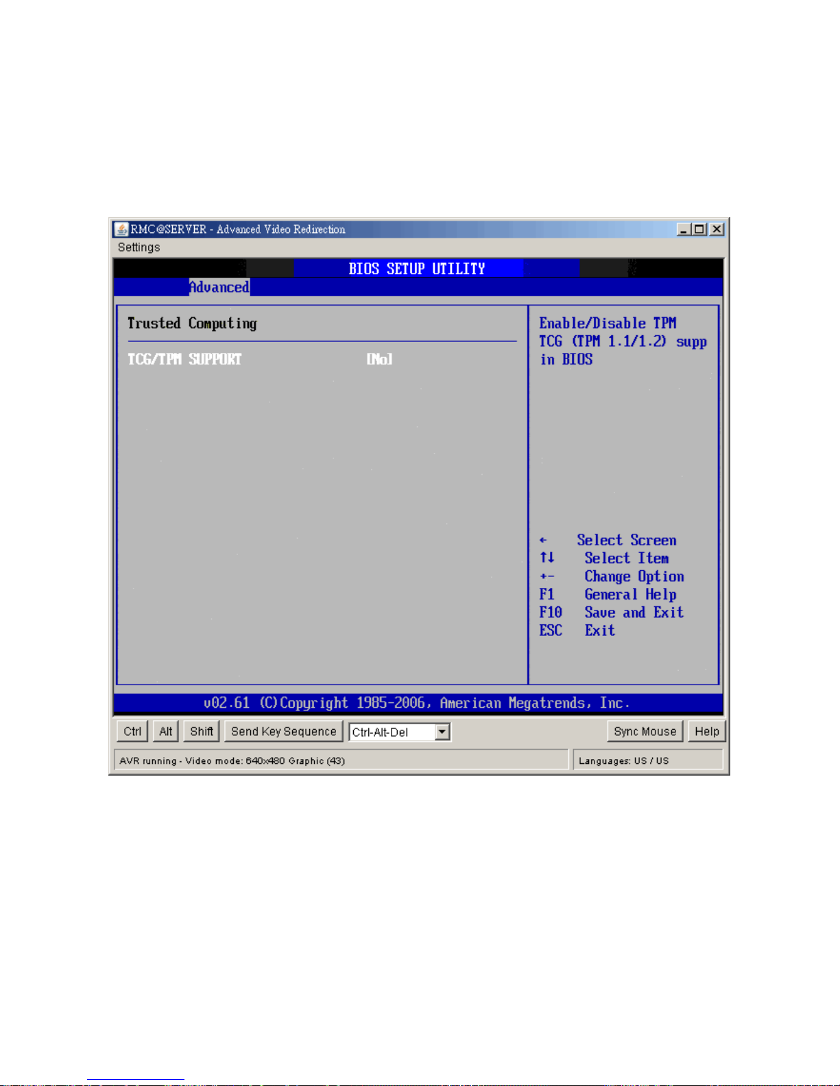
2.4.8 Trusted Computing
You can use this screen to select options for the Intel Trusted Computing settings. Use the
up and down <Arrow> keys to select an item. Use the <Plus> and <Minus> keys to change
the value of the selected option. The settings are described on the following pages. The
screen is shown below.
y TCG/TPM SUPPORT
Enable or disable TPM TCG (TPM 1.1/1.2) support in BIOS.
Page 70
IX45GM
70
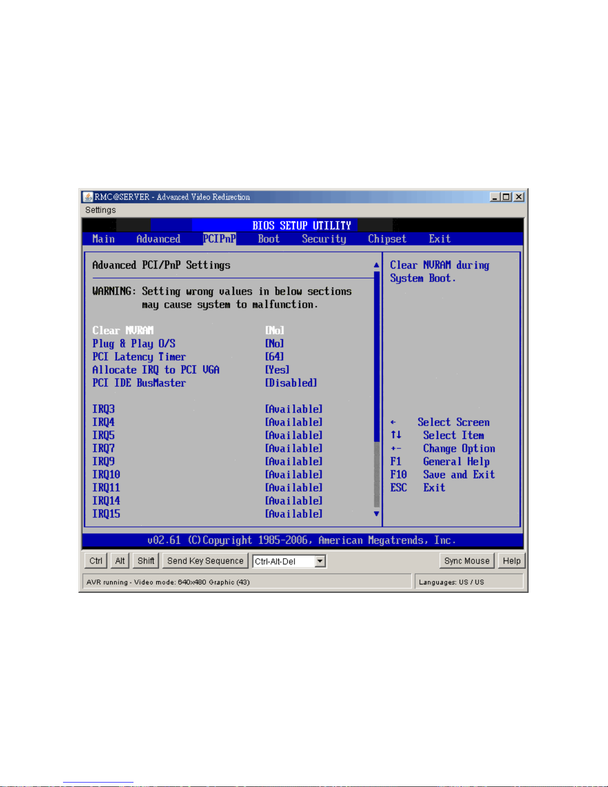
2.5 Advanced PCI/PnP Settings
Select the PCI/PnP tab from the setup screen to enter the Plug and Play BIOS Setup
screen. You can display a Plug and Play BIOS Setup option by highlighting it using the
<Arrow> keys. All Plug and Play BIOS Setup options are described in this section. The Plug
and Play BIOS Setup screen is shown below.
2.5.1 Clear NVRAM
This item is to clear NVRAM during system boot. The choices are No or Yes.
2.5.2 Plug & Play O/S
Set this value to allow the system to modify the settings for Plug and Play operating system
support. The default setting is No.
Page 71

User’s Manual
IX45GM
71
Option Description
No The No setting is for operating systems that do not meet the Plug and Play
specifications. It allows the BIOS to configure all the devices in the system. This
is the default setting.
Yes The Yes setting allows the operating system to change the interrupt, I/O and
DMA settings. Set this option if the system is running Plug and Play aware
operating systems.
2.5.3 PCI Latency Timer
Set this value to allow the PCI Latency Timer to be adjusted. This option sets the latency of
all PCI devices on the PCI bus. The default setting is 64.
Option Description
32 This option sets the PCI latency to 32 PCI clock cycles.
64 This option sets the PCI latency to 64 PCI clock cycles. This is the default
setting.
96 This option sets the PCI latency to 96 PCI clock cycles.
128 This option sets the PCI latency to 128 PCI clock cycles.
160 This option sets the PCI latency to 160 PCI clock cycles.
192 This option sets the PCI latency to 192 PCI clock cycles.
224 This option sets the PCI latency to 224 PCI clock cycles.
248 This option sets the PCI latency to 248 PCI clock cycles.
2.5.4 Allocate IRQ to PCI VGA
Set this value to allow or restrict the system from giving the VGA adapter card an interrupt
address. The default setting is Yes.
Option Description
Yes Set this value to allow the allocation of an IRQ to a VGA adapter card that uses
the PCI local bus. This is the default setting.
No Set this value to prevent the allocation of an IRQ to a VGA adapter card that
uses the PCI local bus.
2.5.5 PCI IDE BusMaster
Set this value to allow or prevent the use of PCI IDE busmastering. The setting is Disabled.
Option Description
Disabled Set this value to prevent PCI busmastering. This is the default setting.
Enabled This option specifies that the IDE controller on the PCI local bus has mastering
capabilities.
Page 72

IX45GM
72
2.5.6 IRQ
Set this value to allow the IRQ settings to be modified. The default setting is available.
Interrupt Option Description
IRQ3
IRQ4
IRQ5
IRQ7
IRQ9
IRQ10
IRQ11
IRQ14
IRQ15
Available This setting allows the specified IRQ to be used by a PCI/PnP
device. This is the default setting.
Reserved This setting allows the specified IRQ to be used by a legacy ISA
device.
2.5.7 DMA
Set this value to allow the DMA setting to be modified. The default setting is Available.
DMA Channel Option Description
DMA Channel 0
DMA Channel 1
DMA Channel 3
DMA Channel 5
DMA Channel 6
DMA Channel 7
Available This setting allows the specified DMA to be used by PCI/PnP
device. This is the default setting.
Reserved This setting allows the specified DMA to be used by a legacy
ISA device.
Page 73
User’s Manual
IX45GM
73
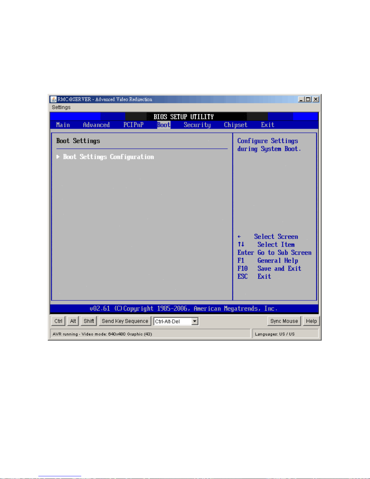
2.6 Boot Setting Configuration
Select the Boot tab from the setup screen to enter the Boot Setup screen. You can display
a Boot Setup option by highlighting it using the <Arrow> keys. All Boot BIOS Setup options
are described in this section. The Boot BIOS Setup screen is shown below.
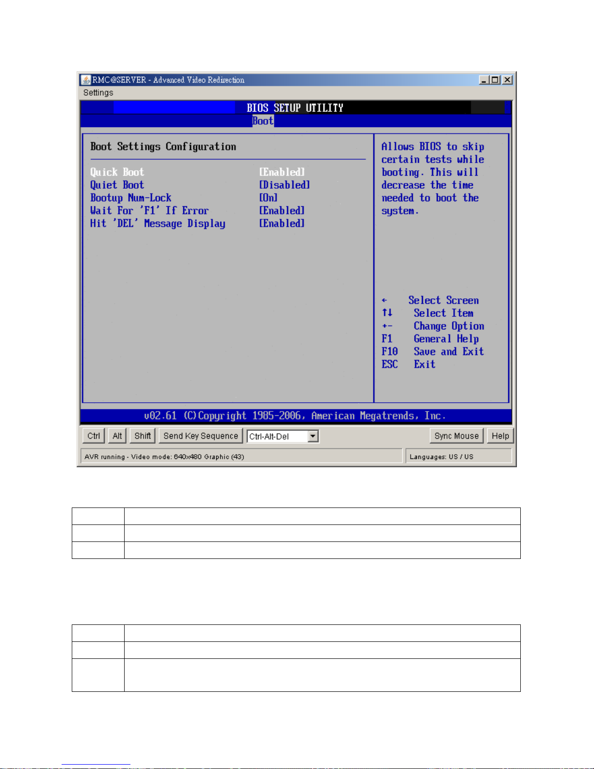
2.6.1 Boot Settings Configuration
You can use this screen to select options for the Boot settings. Use the up and down
<Arrow> keys to select an item. Use the <Plus> and <Minus> keys to change the value of
the selected option. The settings are described on the following pages. The screen is
shown below.
Page 74
IX45GM
74
y Quick Boot
The default setting is Enabled.
Option Description
Disabled Set this value to allow the BIOS to perform all POST tests.
Enabled Set this value to allow the BIOS to skip certain POST tests to boot faster.
y Quiet Boot
Set this value to allow the boot up screen options to be modified between POST messages
or OEM logo. The default setting is Disabled.
Option Description
Disabled Set this value to allow the computer system to display the POST messages.
Enabled Set this value to allow the computer system to display the OEM logo. This is the
default setting.
Page 75

User’s Manual
IX45GM
75
y Bootup Num-Lock
Set this value to allow the Number Lock setting to be modified during boot up. The default
setting is On.
Option Description
Off This option does not enable the keyboard Number Lock automatically. To use
the 10-keys on the keyboard, press the Number Lock key located on the upper
left-hand corner of the 10-key pad. The Number Lock LED on the keyboard will
light up when the Number Lock is engaged.
On Set this value to allow the Number Lock on the keyboard to be enabled
automatically when the computer system is boot up. This allows the immediate
use of 10-keys numeric keypad located on the right side of the keyboard. To
confirm this, the Number Lock LED light on the keyboard will be lit. This is the
default setting.
y Wait For “F1” If Error
Set this value to allow the Wait for “F1” Error setting to be modified. The default setting is
Enabled.
Option Description
Disabled This prevents the to wait on an error for user intervention. This setting should be
used if there is a known reason for a BIOS error to appear. An example would
be a system administrator must remote boot the system. The computer system
does not have a keyboard currently attached. If this setting is set, the system will
continue to boot up in to the operating system. If “F1” is enabled, the system will
wait until the BIOS setup is entered.
Enabled Set this value to allow the system BIOS to wait for any error. If an error is
detected, pressing <F1> will enter Setup and the BIOS setting can be adjusted
to fix the problem. This normally happens when upgrading the hardware and not
setting the BIOS to recognized it. This is the default setting.
y Hit “DEL” Message Display
Set this value to allow the Hit “DEL” to enter Setup Message Display to be modified. The
default setting is Enabled.
Option Description
Disabled This prevents to display “Hit Del to Enter Setup” during memory initialization. If
Quiet Boot is enabled, the message will not display.
Enabled This allows to display “Hit Del to Enter Setup” during memory initialization. This
is the default setting.
Page 76
IX45GM
76
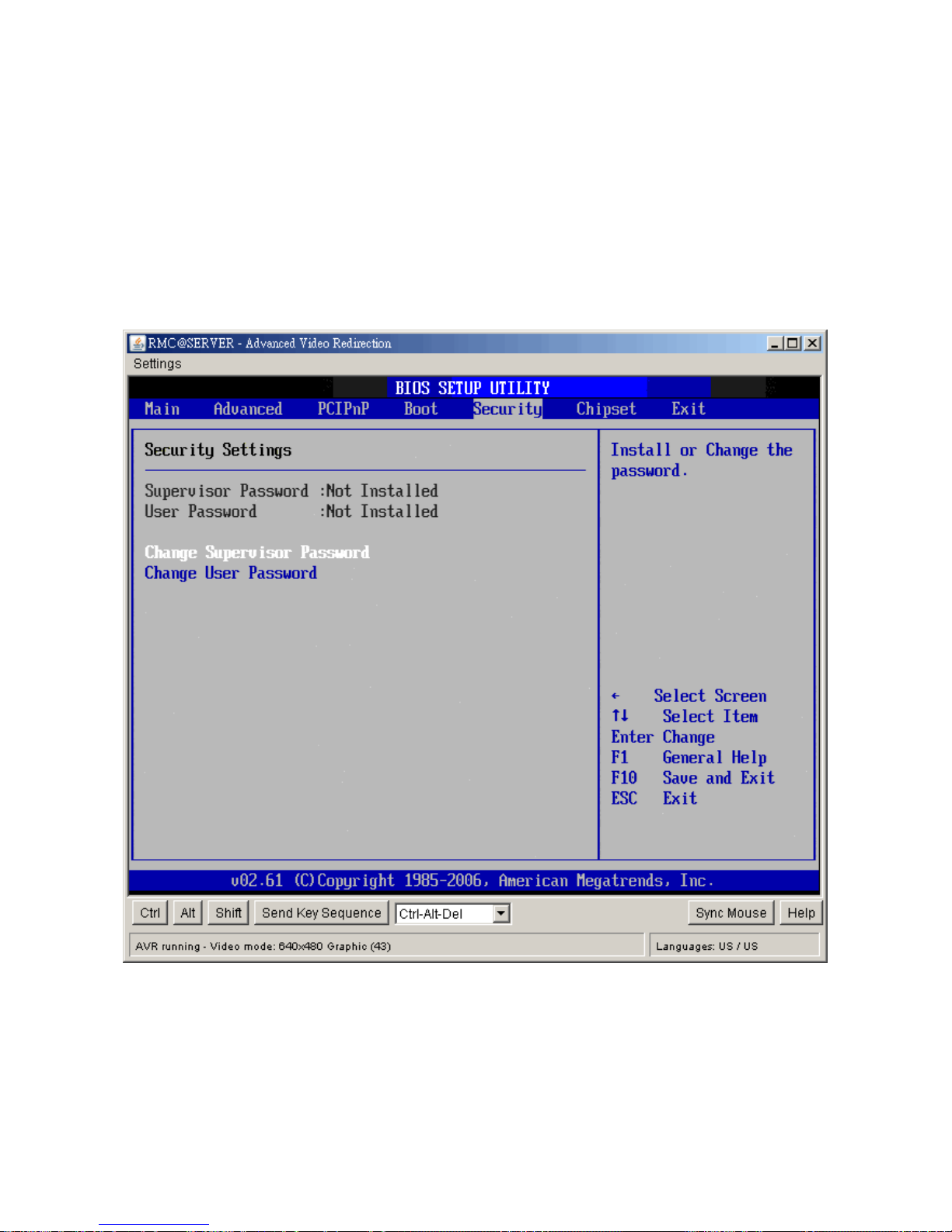
2.7 Security Setup
Select Security Setup from the Setup main BIOS setup menu. All Security Setup options,
such as password protection and virus protection, are described in this section. To access
the sub menu for the following items, select the item and press <Enter>:
y Change Supervisor Password
The Security Setup screen is shown below. The sub menus are documented on the
following pages.
2.7.1 Change Supervisor Password
This item indicates whether a supervisor password has been set. If the password has been
installed, Installed displays. If not, Not Installed displays.
2.7.2 Change User Password
This item indicates whether a user password has been set. If the password has been
installed, Installed displays. If not, Not Installed displays.
Page 77
User’s Manual
IX45GM
77
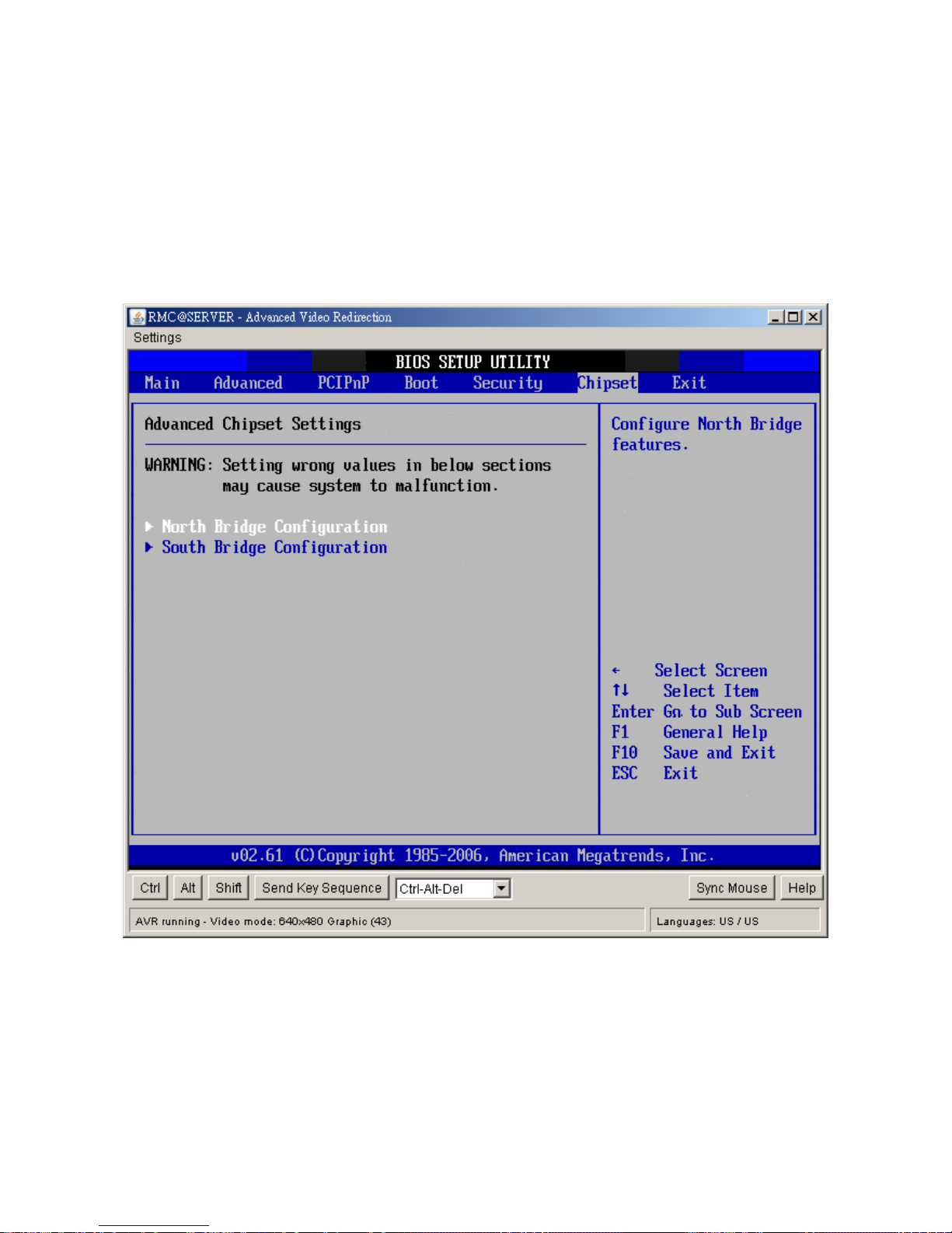
2.8 Chipset Setup
Select the Chipset tab from the setup screen to enter the Chipset BIOS Setup screen. You
can select any of the items in the left frame of the screen, such as CPU Configuration, to go
to the sub menu for that item. You can display a Chipset BIOS Setup option by highlighting
it using the <Arrow> keys. All Chipset BIOS Setup options are described in this section.
The Chipset BIOS Setup screen is shown below.
Page 78
IX45GM
78
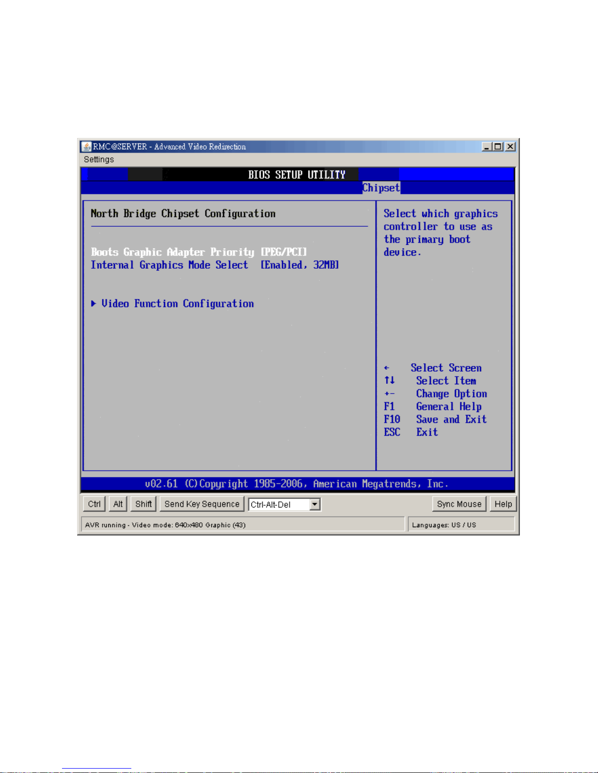
2.8.1 North Bridge Configuration
You can use this screen to select options for the North Bridge Configuration. Use the up
and down <Arrow> keys to select an item. Use the <Plus> and <Minus> keys to change the
value of the selected option.
Note: The North Bridge Configuration setup screen varies depending on the supported
North Bridge chipset.
y Boots Graphics Adaptor Priority
This item selects which graphics controller to use as the primary boot device. The options
are IGD, PCI/IGD, PCI/PEG, PEG/IGD, PEG/PCI. The default setting is PEG/PCI.
y Internal Graphics Mode Select
This item selects the amount of system memory used by the internal graphics device. The
choices are Disabled, Enabled 32MB, Enabled 64MB, and Enabled 128MB.
Page 79

User’s Manual
IX45GM
79
y Video Function Configuration
y DVMT Mode Select
Use this field to select the memory to allocate for video memory. The choice is
“DVMT”.
- DVMT/Fixed Memory Size
Specify the size of DVMT/system memory to allocate for video memory. The
options are 128MB, 256MB and Maximum DVMT.
y Boot Display Device
Use the field to select the type of device you want to use as the display(s) of the system.
y Flat Panel Type
This setting allows you to set your preferences for the boot display device.
Page 80

IX45GM
80
y Spread Spectrum
This setting allows you to reduce EMI by modulating the signals the CPU generates so that
the spikes are reduced to flatter curves. This is achieved by varying the frequency slightly
so that the signal does not use any particular frequency for more than a moment. The
options: Disabled and Enabled.
y HDCP Support
HDCP(High-Bandwidth Digital Content Protection) is a copy protection protocol that was
designed by Intel to prevent copying protected media as it travels across data lines. The
choice are Disabled and Enabled
Page 81
User’s Manual
IX45GM
81
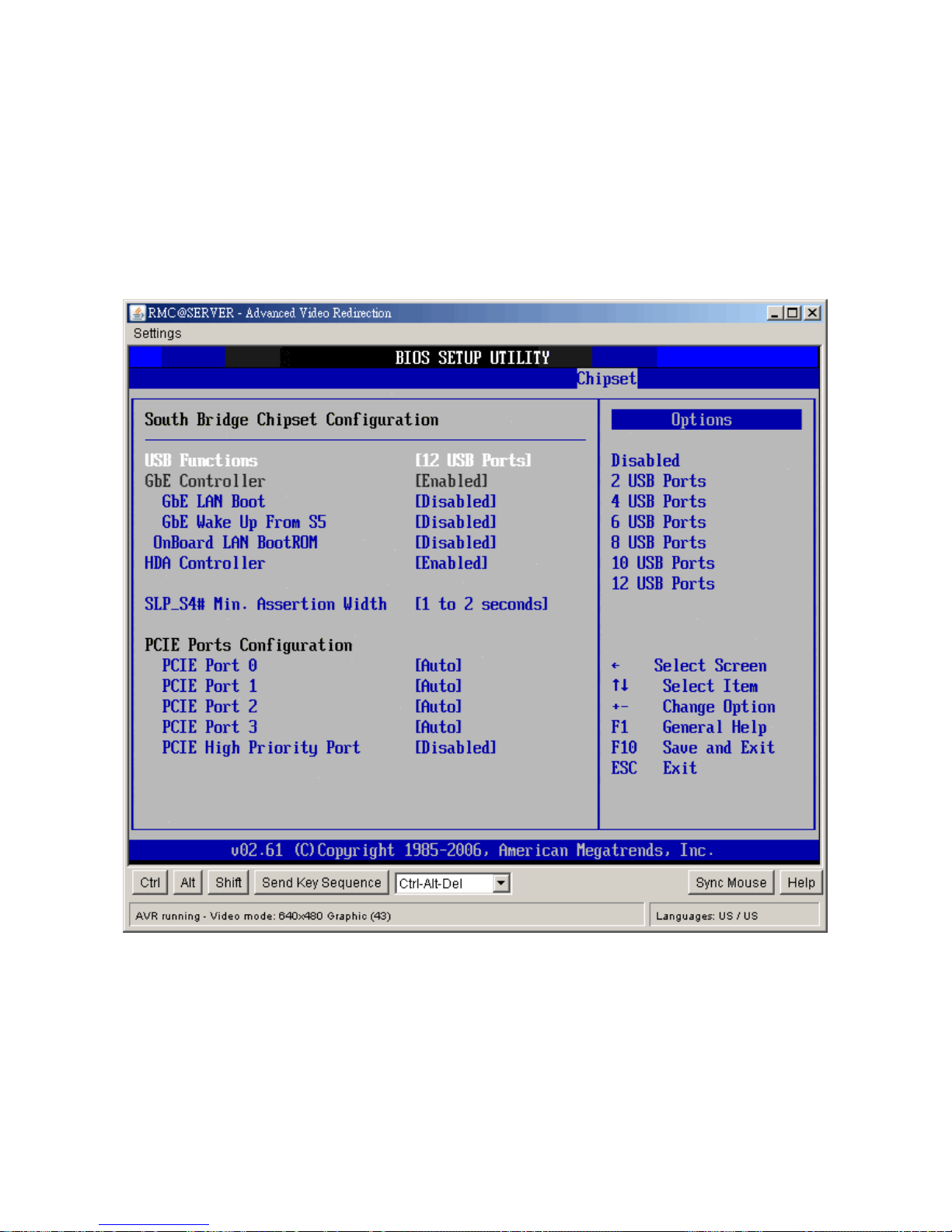
2.8.2 South Bridge Configuration
You can use this screen to select options for the South Bridge Configuration. South Bridge
is a chipset on the motherboard that controls the basic I/O functions, USB ports, audio
functions, modem functions, IDE channels, and PCI slots. Use the up and down <Arrow>
keys to select an item. Use the <Plus> and <Minus> keys to change the value of the
selected option.
y USB Functions
Set this value to allow the system to enable or disable the onboard USB ports. The choices
are Disabled, 2 USB Ports, 4 USB Ports, 6 USB Ports, 8 USB Ports, 10 USB Ports, 12 USB
Ports.
y GbE Controller
Options are “Enabled” and “Disabled”. Select “Disabled” if you don’t want to use onboard
Page 82

IX45GM
82
LAN controller.
- GbE LAN Boot
When [Enabled], the BIOS attempts to boot from a LAN boot image before it
attempts to boot from a local storage device.
- GbE Wake up From S5
This field specifies whether the system will be awakened from the S5 power
saving mode when activity or input signal of onboard LAN is detected.
y OnBoard LAN Boot ROM
Options are “Enabled” and “Disabled”. Select “Disabled” if you don’t want to use onboard
LAN Boot Rom.
y HDA Controller
Options are “Enabled” and “Disabled”. Select “Disabled” if you don’t want to use HDA
controller.
y SLP_S4# Min. Assertion Width
The choices are 4 to 5 seconds, 3 to 4 seconds, 2 to 3 seconds, and 1 to 2 seconds.
y PCIE Ports Configuration
Option Description
PCIE Port 0 This setting allows to enable the PCIE Port 0. The choices
are Auto, Enabled, and Disabled.
PCIE Port 1 This setting allows to enable the PCIE Port 1. The choices
are Auto, Enabled, and Disabled.
PCIE Port 2 This setting allows to enable the PCIE Port 2. The choices
are Auto, Enabled, and Disabled.
PCIE Port 3 This setting allows to enable the PCIE Port 3. The choices
are Auto, Enabled, and Disabled.
PCIE High Priority Port This setting allows to select the PCIE High Priority Port. The
choices are Disabled, Port 0, Port 1, Port 2 and Port 3.
Page 83
User’s Manual
IX45GM
83
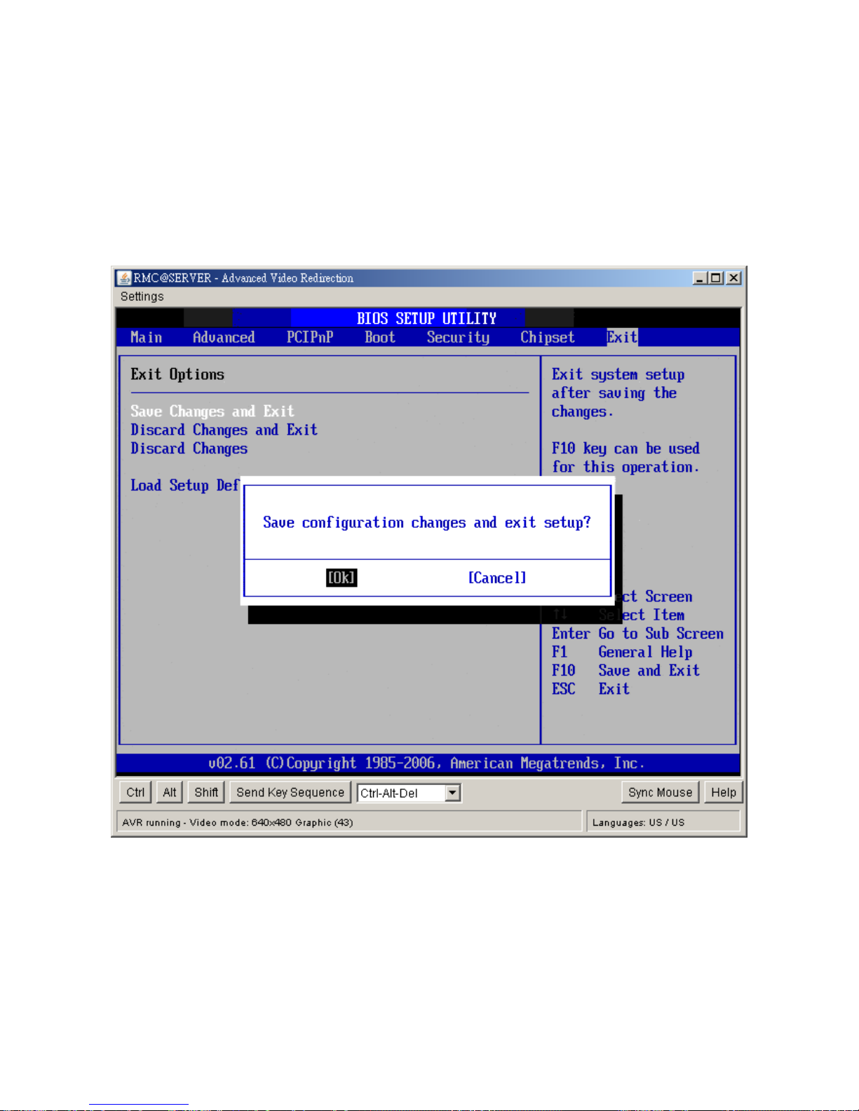
2.9 Exit Menu
Select the Exit tab from the setup screen to enter the Exit BIOS Setup screen. You
can display an Exit BIOS Setup option by highlighting it using the <Arrow> keys. All
Exit BIOS Setup options are described in this section. The Exit BIOS Setup screen is
shown below.
Page 84
IX45GM
84
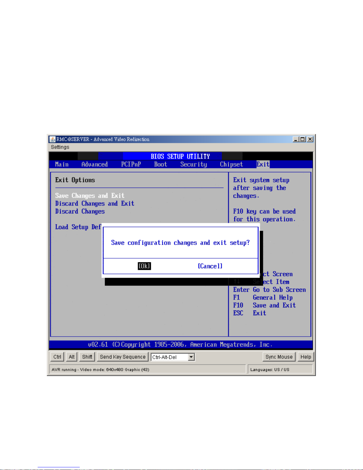
2.9.1 Save Chan ges and Exit
When you have completed the system configuration changes, select this option to
leave
Setup and reboot the computer so the new system configuration parameters can
take effect. Select Exit Saving Changes from the Exit menu and press <Enter>.
Save Configuration Changes and Exit Now?
[Ok] [Cancel]
appears in the window. Select Ok to save changes and exit.
Page 85
User’s Manual
IX45GM
85
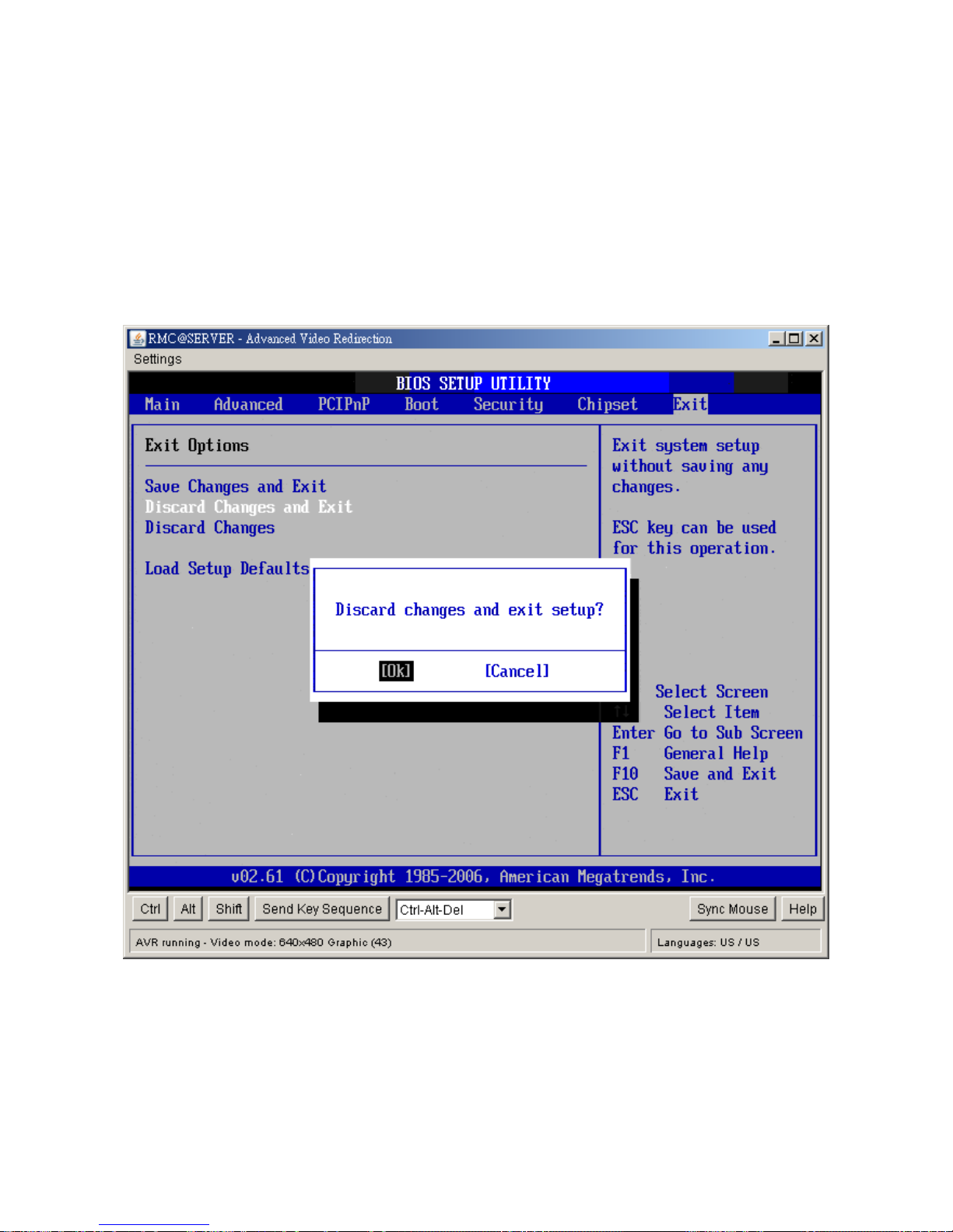
2.9.2 Discard Changes an d Exit
Select this option to quit Setup without making any permanent changes to the
system configuration. Select Exit Discarding Changes from the Exit menu and press
<Enter>.
Discard Changes and Exit Setup Now?
[Ok] [Cancel]
appears in the window. Select Ok to discard changes and exit.
Page 86
IX45GM
86
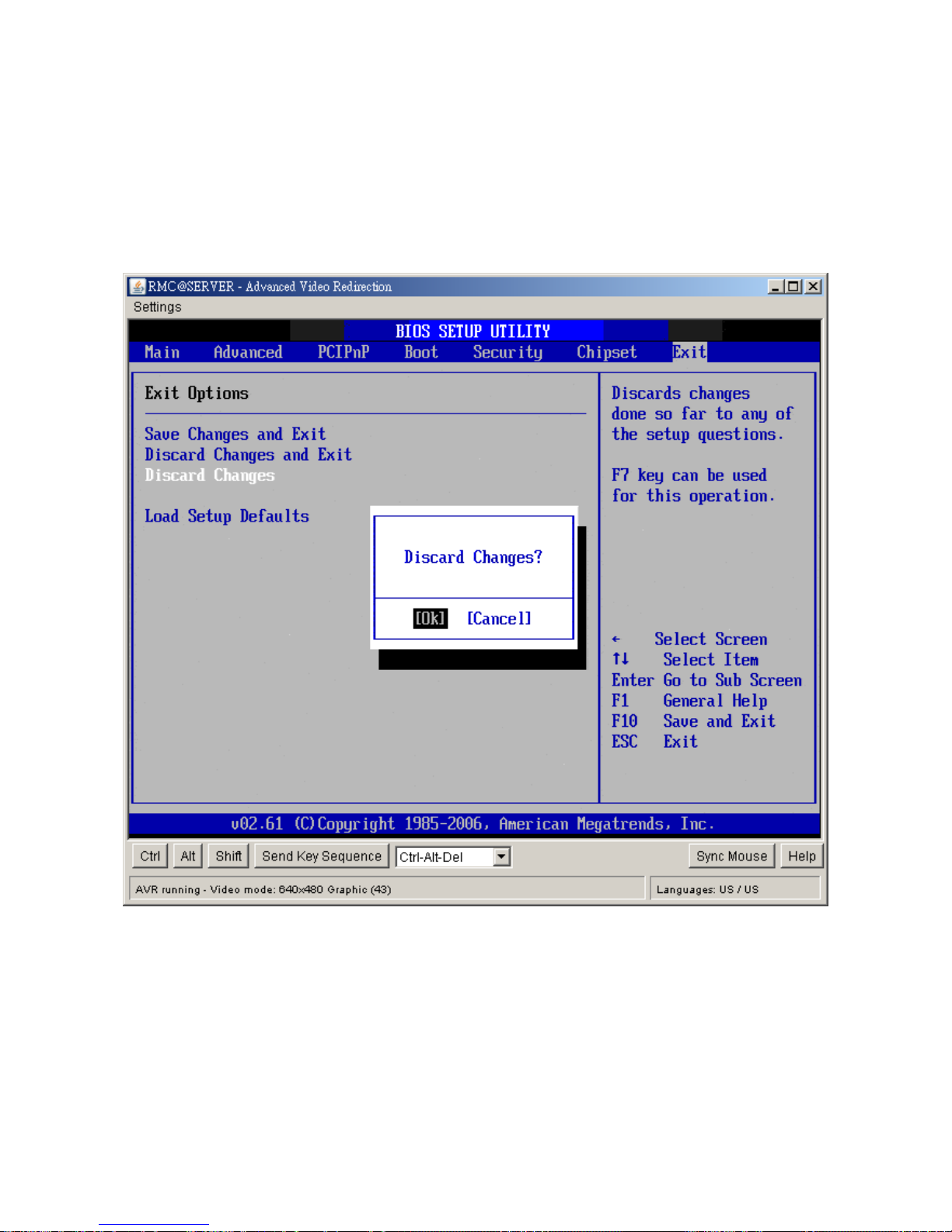
2.9.3 Discard Changes
Select Discard Changes from the Exit menu and press <Enter>.
Discard Changes ?
[Ok] [Cancel]
appears in the window. Select Ok to discard changes.
Page 87
User’s Manual
IX45GM
87
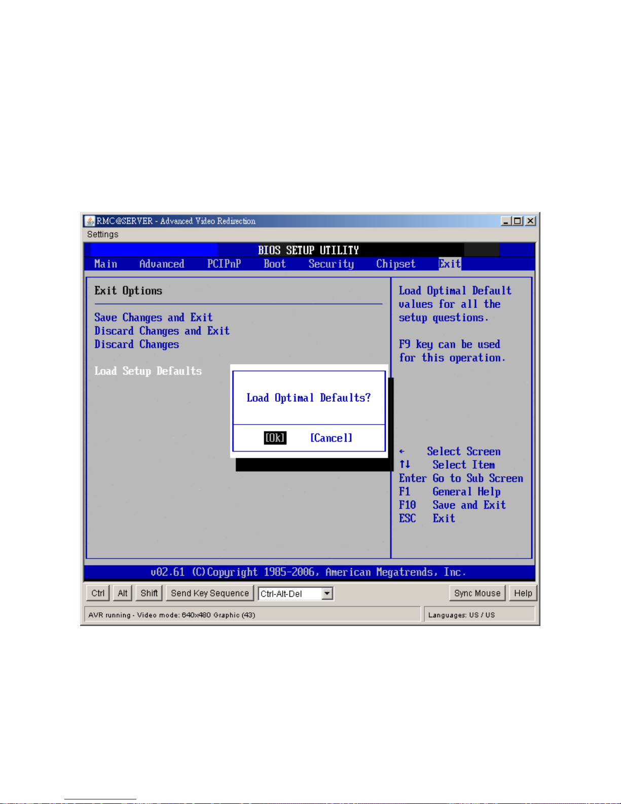
2.9.4 Load Setup Default
Automatically sets all Setup options to a complete set of default settings when you
Select this option. The Optimal settings are designed for maximum system
performance, but may not work best for all computer applications. In particular, do
not use the Optimal Setup options if your computer is experiencing system
configuration problems. Select Load Setup Defaults from the Exit menu and press
<Enter>. Select Ok to load optimal defaults.
 Loading...