

Page 1
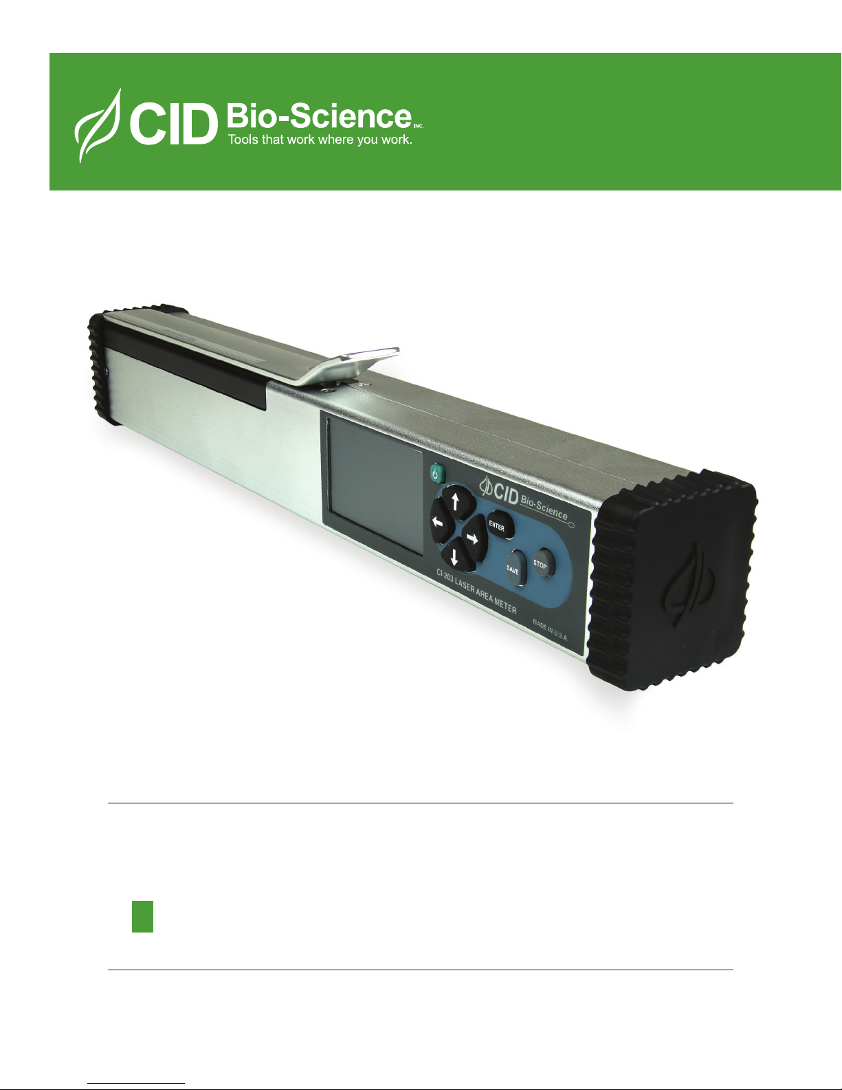
Operations Manual
CI-203
Handheld Laser Leaf Area Meter
Page 2

CI-203 Instruction Manual rev. 8/9/2016
DOCUMENT OVERVIEW
INTRODUCTION ................................................................................................................................................................................................2
Specifications ........................................................................................................................................................................ 2
Features ................................................................................................................................................................................... 2
OPERATING INSTRUCTIONS .......................................................................................................................................................................4
Menus and What They Do ................................................................................................................................................ 5
MEASURE MENU ..............................................................................................................................................................................................5
SETUP INSTRUMENT MENU .......................................................................................................................................................................7
Setup AutoSave Feature ................................................................................................................................................... 7
Setup Measure ...................................................................................................................................................................... 7
Setup Scanner Thresholds ............................................................................................................................................... 8
Threshold Adjustment (Width Calibration) ........................................................................................................ 8
Calibration of the Scanner Length ........................................................................................................................... 9
Setup Scanner Filter ...................................................................................................................................................... 9
Setup Scanner Adjustment Menu ............................................................................................................................ 9
Setup Storage (SPI Flash Management) .................................................................................................................. 10
Setup Time and Date ....................................................................................................................................................... 11
Setup SDcard ...................................................................................................................................................................... 11
VIEW MENU ..................................................................................................................................................................................................... 12
View Files ............................................................................................................................................................................. 12
GPS System Features ................................................................................................................................................. 13
Other View Menu Options ....................................................................................................................................... 13
FILE MENU ....................................................................................................................................................................................................... 14
Clear a File ........................................................................................................................................................................... 14
Delete a File ........................................................................................................................................................................ 14
Create a File ........................................................................................................................................................................ 15
Transfer Data to a Computer ....................................................................................................................................... 16
Wireless Transfer ........................................................................................................................................................ 17
How Data Appears in a File .......................................................................................................................................... 18
How to Work With or Manipulate Data Files ........................................................................................................ 18
THEORY OF OPERATION ........................................................................................................................................................................... 19
Overview of the Parts of the Instrument ................................................................................................................ 19
The Width Scanner .......................................................................................................................................................... 19
The Length Step (Roller System) ............................................................................................................................... 19
Computing the Parameters .......................................................................................................................................... 19
Computing Aspect Ratio and Shape Factor Information .................................................................................. 20
CARE AND CLEANING ................................................................................................................................................................................. 21
Charging the Battery ....................................................................................................................................................... 21
Taking Care of the Rubber Roller in the CI-203................................................................................................... 21
TROUBLESHOOTING ................................................................................................................................................................................... 22
Technical Support ............................................................................................................................................................ 22
Customer Service .............................................................................................................................................................. 22
Error Message .................................................................................................................................................................... 23
Frequently Asked Questions ........................................................................................................................................ 24
CI-203 Firmware Upgrade ............................................................................................................................................ 26
CI-203 Driver Installation ............................................................................................................................................. 26
Re-computing the CI-203 Parameters ..................................................................................................................... 27
APPENDIX I: OPERATING THE CI-203 LASER LEAF AREA METER WITH THE CI-203CA CONVEYOR
ATTACHMENT ................................................................................................................................................................................................ 28
Hardware Setup ................................................................................................................................................................ 28
Measure ................................................................................................................................................................................ 31
Page 3

CI-203 Instruction Manual rev. 8/9/2016
1554 NE 3rd Ave, Camas, WA 98607, USA
Phone (360) 833-8835 Fax (360) 833-1914 [email protected] http://www.cid-inc.com
1
CI-203 Conveyor Calibration with CI-203 .............................................................................................................. 32
Setup Instrument .............................................................................................................................................................. 33
Changing the CI-203CA Springs ................................................................................................................................. 33
Unavailable Parameters ................................................................................................................................................ 33
Setup Scanner Threshold .............................................................................................................................................. 33
Restoring Set-Up Data for the CI-203 ...................................................................................................................... 34
Restoring Set-Up Data for the CI-203CA Conveyor Attachment ................................................................... 35
CID BIO-SCIENCE, INC. HARDWARE WARRANTY .......................................................................................................................... 36
CI-203 PRODUCTION TEST CHECK SHEET ....................................................................................................................................... 37
WARRANTY REGISTRATION CARD ...................................................................................................................................................... 38
Page 4

CI-203 Instruction Manual rev. 8/9/2016
1554 NE 3rd Ave, Camas, WA 98607, USA
Phone (360) 833-8835 Fax (360) 833-1914 [email protected] http://www.cid-inc.com
2
INTRODUCTION
Congratulations on the purchase of your new CI-203 Portable Laser Area Meter. Making leaf
measurements, in the field or laboratory, is now very easy with the CI-203 Portable Laser Area
Meter. This state-of-the-art instrument has been designed to be the most portable leaf area
measurement system available. Although you may be anxious to use your new meter, please take the
time to read this manual first. This manual is for instruments with firmware version 4.03.
Specifications
Maximum Capacities:
Thickness: 2.5 cm
Width: 15 cm
Length: 3 m
Area: 1 m
2
Resolution: 1 mm2
Computer Interface: Full speed USB interface 12MBit/s
Area Units: cm2
RAM Memory Size: 64KB
SPI Flash: 1024KB
Storage: HD SD card 16GB
File System: Fat32
Display: TFT LCD 320x240
Scanning Speed: 200 mm/sec
Battery: 7.2 V rechargeable Nickel Metal Hydride (NiMH)
Battery Capacity Over 250 scans per charge
Operating Temperature: 0~50oC
Dimensions: 355L x 45W x 50H mm
Weight: 975 g
Features
Non-destructive measurements
Measures area, length, width and perimeter, saves and displays synthesized images
Calculates shape factor, aspect ratio and voids number in object
Area resolution down to 0.01 cm
2
Unlimited storage capacity (replaceable 4GB SD card)
USB port for viewing/copying files, upgrading firmware and debugging the output
Supports USB mass-storage device class
Serial Flash to store non-volatile scan/file parameters
Single self-contained instrument with built-in LCD display
Measure objects up to 150 mm wide and 25 mm thick of virtually unlimited length
1
1.
1
See specifications for maximum length and area capabilities.
Page 5

CI-203 Instruction Manual rev. 8/9/2016
1554 NE 3rd Ave, Camas, WA 98607, USA
Phone (360) 833-8835 Fax (360) 833-1914 [email protected] http://www.cid-inc.com
3
Easy calibration when required
Rechargeable battery through USB port
Page 6
CI-203 Instruction Manual rev. 8/9/2016
1554 NE 3rd Ave, Camas, WA 98607, USA
Phone (360) 833-8835 Fax (360) 833-1914 [email protected] http://www.cid-inc.com
4
OPERATING INSTRUCTIONS
The CI-203 is a self-contained, hand-held, battery-powered instrument with a built-in display. It
contains an optical scanner to measure leaf width, a roller with a shaft encoder to measure length, and
a microcomputer to coordinate the measurement functions, calculate results, and store collected data.
Taking a measurement is as simple as turning the instrument on, inserting a leaf in the objective, and
drawing it out. The instrument does the rest.
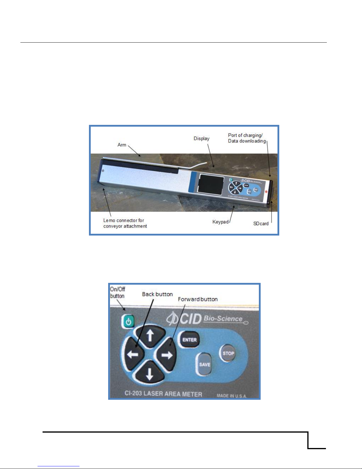
Figure 1. CI-203 Laser Area Meter
To turn the instrument on, press the power button. When the instrument powers on, a copyright
notice will appear for 0.5 seconds. Following this, a menu will appear on the display with the
following options: Measure, Setup, View and File. You are now in the CI-203 menu system.
Figure 2. CI-203 Keypad
Page 7
CI-203 Instruction Manual rev. 8/9/2016
1554 NE 3rd Ave, Camas, WA 98607, USA
Phone (360) 833-8835 Fax (360) 833-1914 [email protected] http://www.cid-inc.com
5
Error messages should rarely appear during normal operation of the CI-203. However, in the event
that the display does not show the “Measure” prompt after displaying the copyright notice, see the
Error Message section of this manual.
Note: To force a power off and reset of the instrument at any point, a user may press and hold
the POWER button for 10 seconds. This “emergency hard shut-down” feature exists to address
hardware or software problems and should not be used except when needed, in general,
simply pressing the Power button in the typical manner will power off the CI-203.
Note: User must create a file (usually blank) before measurements can be taken. Failure to do
so will hang the system in ‘Measurement’ mode, requiring a hard shutdown.
Menus and What They Do
The CI-203 menu system allows you to quickly and easily operate the instrument without repeatedly
consulting the manual. It is recommended to read through the entire manual with the instrument
before performing measurements in the field. The screen associated with a menu item will give you
information about the choices that you can make or the options that are available. Pressing the right
arrow or forward key will select a menu option and move you to the next menu. Pressing the left
arrow or backward key will move you back to the previous menu screen.
MEASURE MENU
In the measure mode, the top line of the screen will read “Measure” on the left with the name of a file
on the right. The bottom line of the screen will have the word “arm” in brackets on the left, and the
four direction arrows on the right.
Measure file00
<arm>
The options are:
to select another file with the UP or DOWN arrow keys
to go back to the main menu with the LEFT arrow key
to take measurements by lifting the arm
To start measuring, open the measurement arm until extended completely, and then allow it to slowly
close upon the leaf to be measured. This begins the measurement process. The motor will start
spinning up to speed as soon as the arm opens, and the display will read “Spinning Up”, “Stabilizing”,
and “Arm Open” in quick succession, then “Measurement” near the top line. When the arm closes, the
laser will power on and the display will read “Measuring”. At this point, draw the leaf being measured
through the instrument. When the leaf has been drawn out completely, the instrument will stop
automatically and display the results of the measurement. With ‘Autofile’ = ON, the measurement is
automatically stored to the currently selected file. With ‘Autofile’ = off, the user must press the ‘SAVE’
button to save the measurement to the currently selected file.
Page 8
CI-203 Instruction Manual rev. 8/9/2016
1554 NE 3rd Ave, Camas, WA 98607, USA
Phone (360) 833-8835 Fax (360) 833-1914 [email protected] http://www.cid-inc.com
6
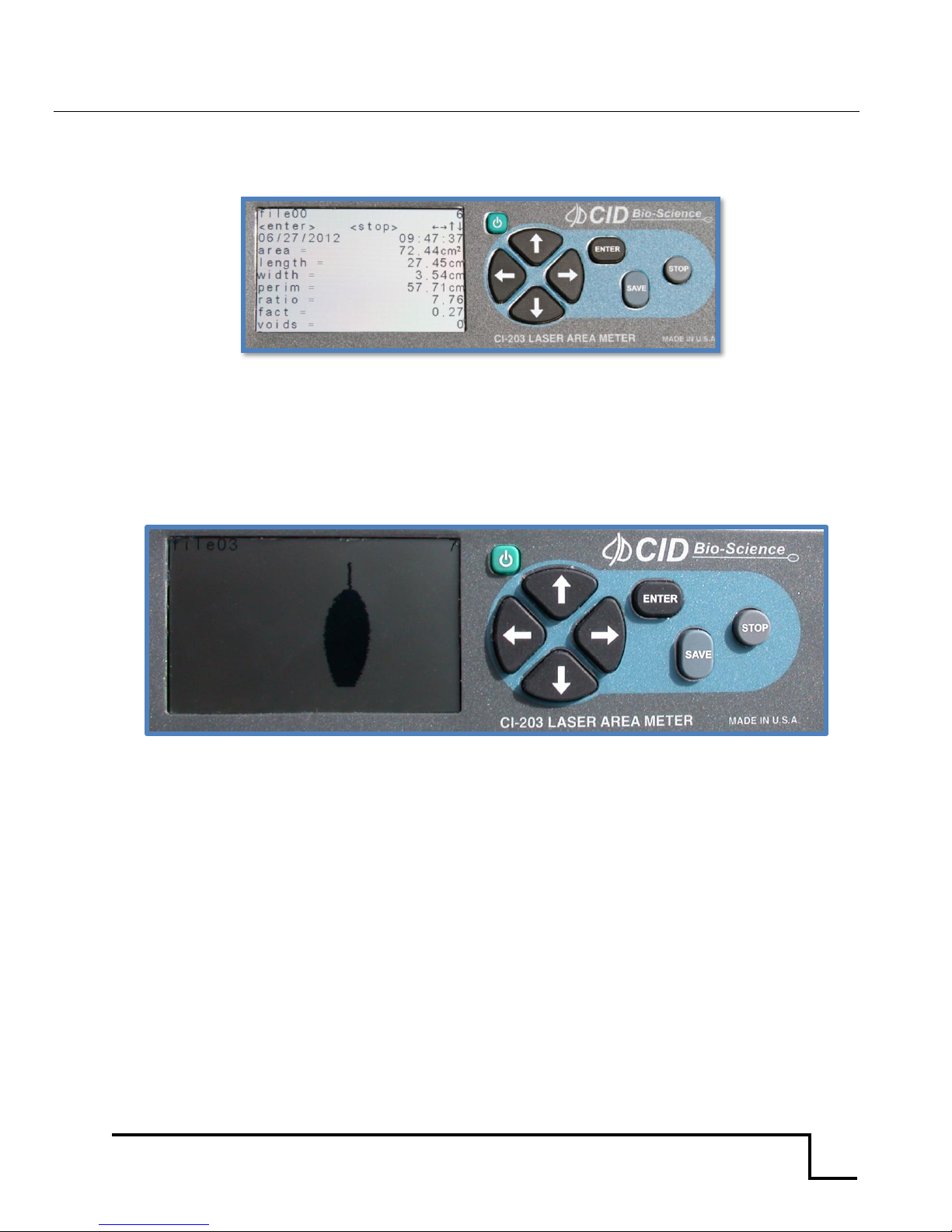
The display will show the name of the current file in the upper left-hand corner of the screen and the
sequence number of the measurement in the upper right-hand corner. Below these the parameter
names appear on the left and parameter values on the right of the screen.
Figure 3. CI-203 display read out and key pad
To bring an image into view, press the RIGHT arrow key. Pressing the RIGHT arrow key again will
display the barcode data. Pressing the LEFT arrow key from any screen will return the instrument to
the ready to measure mode. To discard the last measurement, press the STOP button. Now another
measurement may be taken, if required. Depending on the setup of the automatic save function of the
instrument, the measurement will or will not be saved.
Figure 4. Image of measured leaf on CI-203 display screen
To save the measurement, press the SAVE button; the word “saved” will be shown near the top line of
the display to confirm that the data is saved. Make sure the SDcard is present when saving data to a
file. The user may verify and transfer files by connecting the instrument to a computer using the USB
port on the CI-203, or by mounting the SDcard into the SD slot on the computer and using it as a local
drive; then open the file explorer to view the files. Files should be copied from the SDcard and saved
to the hard drive before proceeding with any calculations or data manipulation.
Page 9
CI-203 Instruction Manual rev. 8/9/2016
1554 NE 3rd Ave, Camas, WA 98607, USA
Phone (360) 833-8835 Fax (360) 833-1914 [email protected] http://www.cid-inc.com
7
SETUP INSTRUMENT MENU
The CI-203 has a number of utility functions that allow the user to manage the instrument’s
capabilities. These functions are accessed by pressing the RIGHT arrow when Setup is highlighted on
the Main Menu. The setup utility options are: Autosave, Measure, Scanner, Storage, Time and SDcard.
Use the UP/DOWN arrows to select the desired option and then press the RIGHT arrow to enter the
choice.
Setup AutoSave Feature
Pressing the RIGHT key when Autosave is highlighted enters the Autosave feature. This allows the
user to setup the instrument to automatically store measurements, and to start a new measurement
without explicitly saving the old one. This mode is convenient when taking fast, repetitive
measurements as well as when it is not necessary to review each measurement immediately after
taking it.
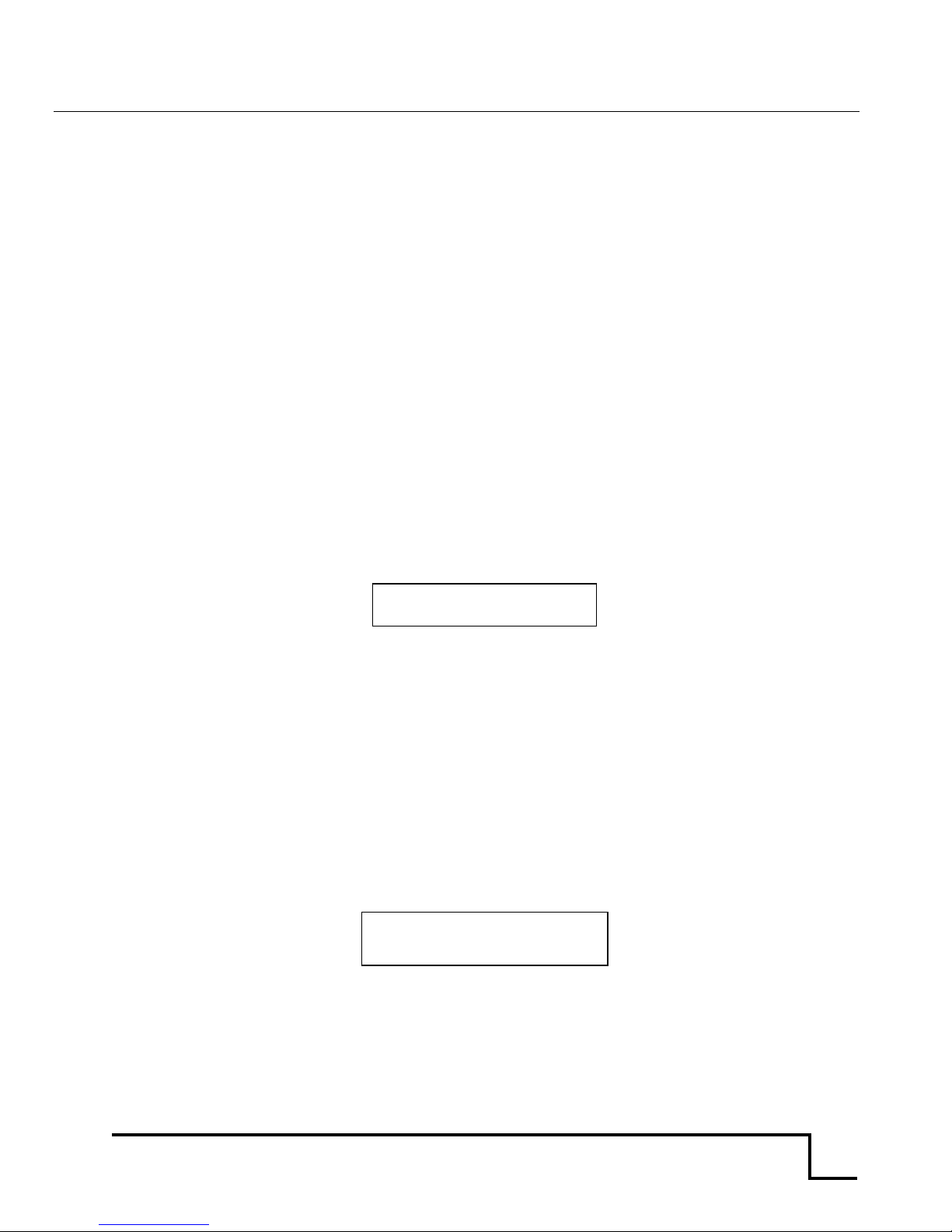
In the Autosave setup mode, the top line of the display will read “autosave =” on the left and either
“yes” or “no” on the right. The bottom line of the display will read “stop” and “save” and the
directional arrows.
Autosave = yes
<stop> <save>
To set the instrument up to automatically store measurements press the UP/DOWN arrow key until
the word “yes” is on the display, then press the SAVE key to save the configuration. To set the
instrument up to automatically discard measurements, press the UP/DOWN arrow key until “no” is on
the display, then press the SAVE key to save the configuration. To avoid changing the configuration,
press the STOP key to exit back to the Setup Menu.
Setup Measure
Pressing the RIGHT key when Measure is highlighted enters the Setup Measure mode. Here the user
can switch between Leaf and Root mode using the UP/DOWN arrows. For instructions to access
Conveyor mode, see Appendix I of this manual. Press SAVE when the desired mode is on the display.
Press STOP to go back to the Setup Menu.
The Measure Leaf mode is the regular mode for doing leaf measurements using the CI-203 and the
arm. When the instrument is in Root Mode, the arm is removed and the instrument is used in
conjunction with the CI-203RL root length tray accessory. Please see Appendix II of this manual for
more information about using the CI-203 in Measure Root mode.
Measure = Leaf
<stop> <save>
Page 10

CI-203 Instruction Manual rev. 8/9/2016
1554 NE 3rd Ave, Camas, WA 98607, USA
Phone (360) 833-8835 Fax (360) 833-1914 [email protected] http://www.cid-inc.com
8
Setup Scanner Thresholds
NOTE: Normally, there is no need to adjust the threshold of the CI-203 because the instruments
are factory-adjusted to a threshold level that is ideal for “all-around” use.
The CI-203 automatically adjusts an internal threshold to a level that is optimum for detecting the
presence of a leaf in the scanner objective. If out-of-the-ordinary measurements are being recorded
or if the instrument has suffered from abuse or excessive aging, the manual threshold setting may
need to be adjusted. If the instrument appears to be making incorrect measurements, make sure the
instrument is clean and the reflective tape and the objective window appears to be undamaged and in
good condition. If there is something blocking the optical path in the scanner, no amount of threshold
adjustment will correct the problem. Refer to the section on cleaning and maintenance for more
information on insuring that the instrument is clean. Please do not hesitate to consult with the
manufacturer or with the nearest manufacturer’s representative if there is a problem and the
threshold needs adjustment.
Use the UP/DOWN arrow to highlight Scanner on the Setup Menu display. Next, press the RIGHT
arrow to enter the Setup Scanner menu. The options on the Setup Scanner menu include HiThld
(High Threshold), LoThld (Low Threshold), Manual, Filter and Adjustment. Use the UP/DOWN key to
switch between options and the RIGHT arrow to select.
Threshold Adjustment (Width Calibration)
In the event you need to alter the normal threshold settings, perform the following steps. First, check
the threshold of the CI-203 alone, with its arm in place. To do so, access the Setup Scanner menu,
select “HiThld” and press the RIGHT arrow key. The instrument’s motor will turn on and a “t” and “w”
value will appear and count down on the display. Next, the display will show the high threshold value
briefly before returning to the Scanner Setup menu. Make note of the HiThld value.
Next, switch to “LoThld” menu and place a piece of white paper under the arm and press the RIGHT
arrow key. Let the scanner run. The display will show a t value that counts down and w=0. When the
t value is done counting down, the final Low Threshold value (t= ) will display briefly before exiting
back to the Scanner Setup menu. Make note of the LoThld value.
Remove the paper from under the arm. Next, select ‘Manual’ from the Scanner Setup menu by
pressing the RIGHT arrow key. Make sure that the width reads 0 when there is no object under the
arm. Stop the Manual scan and the motor by pressing the STOP key. On the scanner menu, scroll
down to ‘Adjustment’. Here is where the user can adjust the width measurement based on the high
and low threshold values. After increasing or decreasing the Manual threshold value, press STOP.
You will be prompted to STOP (discard changes) or SAVE changes if you made any.
The next step is very important: every time the threshold is changed in any mode, switch to the
“Measure” menu and press the LEFT and RIGHT key at the same time. The instrument will
automatically compute and save the timing parameters. The user should repeat this computation a
few times allowing the instrument to generate an accurate leaf width reading. Make sure to check the
width reading with and without the filter. When checking the reading without the filter, the width
should be above 0 but still a very small value.
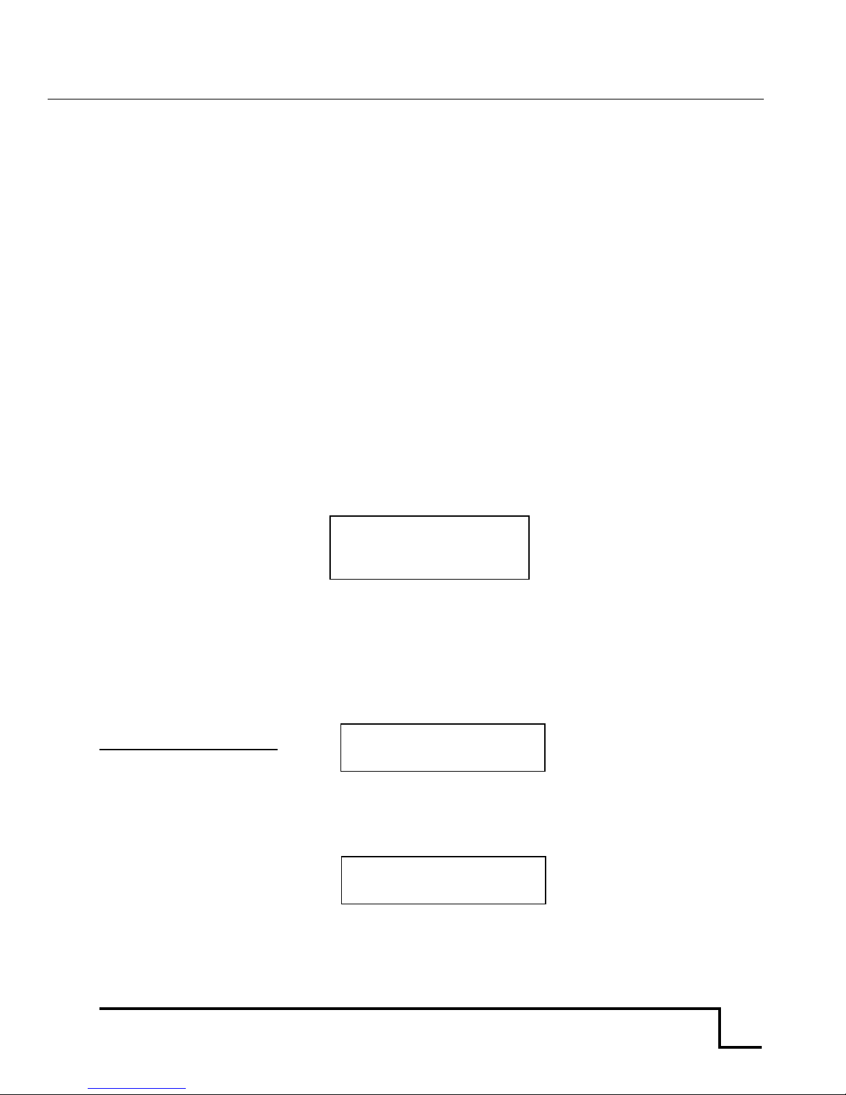
t = 76 w = 0
<stop>
Page 11
CI-203 Instruction Manual rev. 8/9/2016
1554 NE 3rd Ave, Camas, WA 98607, USA
Phone (360) 833-8835 Fax (360) 833-1914 [email protected] http://www.cid-inc.com
9
If the instrument malfunctions after manual threshold adjustment, contact CID Bio-Science, Inc. for
assistance.
Calibration of the Scanner Length
In order to calibrate the scanner step length (step len), from the main menu put the instrument into
‘Measure’ mode. Push the LEFT and DOWN arrow keys simultaneously, or press the RIGHT and DOWN
arrow keys at the same time. This will start the length calibration and the user should be able to see
the scanner laser light under the arm, however the motor will not start or spin up.
Slowly draw a piece of white paper (mounted on an opaque, non-reflective surface) of known length
through the scanner several times. The unit will beep while you do this. A longer beep sound
indicates a better calibration of the scanner lens. After drawing a piece of white paper through the CI203 a few times, push STOP. The lens should now be calibrated. To see the image and measurement
information, press the RIGHT or LEFT arrow keys. Compare known length to measured length.
Setup Scanner Filter
The scanner filter is used to filter out particles on the conveyor cylinder that may be mistaken as
objects to be measured. Press the RIGHT arrow when Filter is highlighted to see the current filter
settings and whether it is turned on or off. Use the UP/DOWN arrows to increase or decrease the size
of the objects to be filtered out. Press the right arrow to toggle the OFF/ON state of the filter. Then
press the left arrow and select Save to choose to make the change or Stop to abort the change and
exit back to the Scanner Setup menu.
Setup Scanner Adjustment Menu
Press the RIGHT arrow when ‘Adjustment’ is highlighted to get to the Setup Scanner Adjustment Menu
which provides access to precharge, scan width, scan time, step length (step len) and scanner defaults.
Press the RIGHT arrow to access the ‘Precharge’ setting and press ENTER to spin up the motor. Press
LEFT or STOP to stop the motor or to exit back to the Scanner Setup Adjustment Menu. Use the
UP/DOWN arrow to change the precharge value in the upper right corner.
Precharge should be at 85
First 2 digits should be 14
At the ‘Scan Width’ selection, press the RIGHT arrow to start the motor spinning up. Press LEFT or
STOP to stop the motor or to exit back to the Setup Scanner Adjustment Menu. Use the UP/DOWN
arrow to change the scan width value in the upper right corner.
It is not recommended that the Reading should be 15xx
User adjust scan width.
Filter On
Value 200
Object 0.787mm
Precharge 85
<stop> 14xxxx: E
Scan width 1575
<stop> 0.00mm
Page 12
CI-203 Instruction Manual rev. 8/9/2016
1554 NE 3rd Ave, Camas, WA 98607, USA
Phone (360) 833-8835 Fax (360) 833-1914 [email protected] http://www.cid-inc.com
10
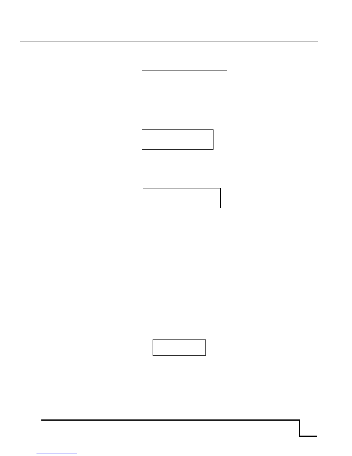
At the ‘Scan Time’ selection, press the RIGHT arrow to start the motor spinning up. Press LEFT or
STOP to stop the motor or to exit back to the Setup Scanner Adjustment Menu. Use the UP/DOWN
arrow to change the scan time value in the upper right corner.
Scan time should be in the
40xxx to 41xxx range.
At the ‘Step Len’ (step length) selection, press the RIGHT. Use the UP/DOWN arrow to change the step
length value in the upper right corner. Press ENTER to increase the step length value to the maximum
of 900. Press STOP to exit back to the Setup Scanner Adjustment Menu. Press STOP again and the
display will prompt to save changes. Press SAVE to save any changes made or press STOP to exit.
Step Length should be 36xx – 37xx
otherwise conduct the scan length
calibration.
Press the RIGHT arrow to access the Scan Defaults menu. Press ENTER and indicate whether you
want to save the defaults by pressing the SAVE key or press STOP to exit. Press LEFT arrow to exit
back to the Setup Scanner Adjustment Menu.
Setup Storage (SPI Flash Management)
SPI (serial peripheral interface) flash plays an important role in the architecture of the CI-203. It
holds all the non-volatile scan parameters, the copy file descriptors, the measurements buffers, etc.
The total size of the serial flash is 1MB, or 16 sectors with 64KB in each sector. Currently the CI-203
uses 4 sectors; sector 0 is inerasable while sectors 1-3 could be erased by the user from the "Set-Up
Storage" menu. Sector 0 is protected because it holds all of the scan/timing parameters. The user is
allowed to modify these parameters, but not to erase them. Sectors 1-3 could be erased thus
eliminating all the files from CI-203.
The user must create at least one (usually blank) file or else the “Measure” function will hang
the system requiring a hard reset. When the user creates a file the instrument allocates data
structure at sector 1 of the serial flash. In addition to this, the same file is created on the SDcard. This
is necessary because the CI-203 uses only special files with the removable SDcard. Without the SDcard
inserted, the instrument is still able scan an object, but cannot store or save the measurement.
space = 128K
<stop>
Scan time 40787
<stop> 0
Step len 3xxx
<stop>
Scan Defaults
<enter> <stop>
Page 13
CI-203 Instruction Manual rev. 8/9/2016
1554 NE 3rd Ave, Camas, WA 98607, USA
Phone (360) 833-8835 Fax (360) 833-1914 [email protected] http://www.cid-inc.com
11
Format Storage
Pressing the UP/DOWN key switches the display to the “format storage” mode screen. Be careful!
Formatting the storage space of the CI-203 will erase all data and all files. This is convenient when
starting a new year’s work, but treat this command with care.
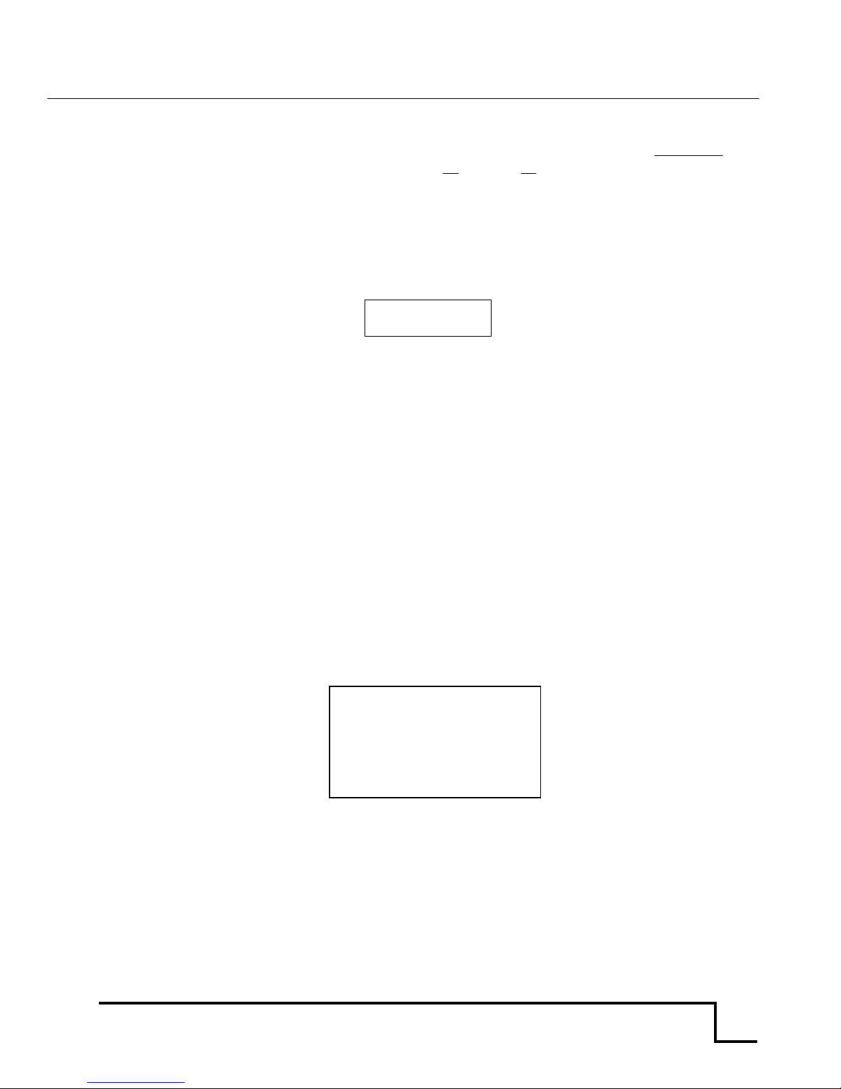
In the format storage mode the top line of the display will read “Clear all data”. The bottom line of the
display will have the word “stop” to the left and “enter” to the right.
Clear all data
<stop> <enter>
To delete every file in your instrument, press the ENTER key. The instrument will erase ALL data
from the memory, leaving the maximum possible amount of memory free for use. To stop the deleting
process and exit Setup ‘Storage’ menu, press the STOP key. To continue measurements, the user
must create a blank file.
Setup Time and Date
To change the time and date stamp on the CI-203, press the RIGHT key when ‘Time’ is highlighted on
the Setup Scanner menu. This utility allows the user to set-up the instrument in different time zones
or to adjust the time after daylight savings.
To change the time on the instrument, use the UP/DOWN arrows to change the values of the first row
(hour: minute: second). Use the LEFT/RIGHT arrow to highlight the appropriate column, make the
appropriate shift in time and press SAVE. To change the date and access the second row, press the
LEFT and RIGHT arrow keys simultaneously. The second row (month: day: year) should now be
highlighted and the date can be changed using the UP and DOWN arrow keys. When done changing
the date, press SAVE or STOP to clear any changes made.
Setup SDcard
The Setup SDcard menu selection is only accessible by CID technicians.
<stop> <save>
14:40:32
04:02:12
Page 14
CI-203 Instruction Manual rev. 8/9/2016
1554 NE 3rd Ave, Camas, WA 98607, USA
Phone (360) 833-8835 Fax (360) 833-1914 [email protected] http://www.cid-inc.com
12
VIEW MENU
The View Menu can be accessed from the main menu screen by pressing the RIGHT arrow key when
“View” is highlighted on the display. This menu allows the user to navigate to and view the files or
data saved on the instrument, as well as check on many features of the CI-203. Options from the View
menu are: Files, Voltage, Battery, Flash, Time, GPS, and SDcard.
View Files
To view collected and saved data, use the ‘View’ mode from the instrument menu. Use the UP/DOWN
arrows to highlight “Files” on the display. Then, press the RIGHT arrow to go forward to select which
file to view. In the View Files mode, the top line of the display will show the word “View” on the left
and the word Files’ on the right. The column beneath ‘View’ shows the file names, while the column
below ‘Files’ lists the number of measurements in that file.
The file name Represents the number
of measurements in the file.
The options are:
Start the viewing process by pressing the RIGHT arrow button
Select a different file (if there is more than one file) with the UP or DOWN arrow keys
The LEFT arrow key will take you back to the files list.
The RIGHT arrow key will scroll the user through the various screens relevant to that
measurement.
Once you have selected a file to view and pressed the RIGHT arrow button, you will be able to look at
the data in the file. The top line of the screen will have the file name at the left. On the right will be
the number of the last recorded measurement (file record number).
file01 6
<stop>
04/03/2012 16:04:16
area = 82.15cm2
length = 15.94cm
width = 8.90cm
perim = 43.50cm
ratio = 1.79
fact = 0.55
voids = 2
Note: Because of the amount of information displayed on this screen the CI-203 cannot display any
prompts in this mode.
View Files
File00 15
Greg17 23
Page 15
CI-203 Instruction Manual rev. 8/9/2016
1554 NE 3rd Ave, Camas, WA 98607, USA
Phone (360) 833-8835 Fax (360) 833-1914 [email protected] http://www.cid-inc.com
13
The data displayed on several different screens include the most current measurement, the GPS
location of measurement, the synthesized scan image and the bar code data. To bring GPS coordinates,
the scan image, or the bar code data into view press the RIGHT arrow key. To bring another
measurement from the file into view, press the UP or DOWN arrow key.
To return to the View File menu, press the STOP/RESET key or the LEFT arrow key. To return to the
View Menu, press the STOP/RESET key again.
GPS System Features
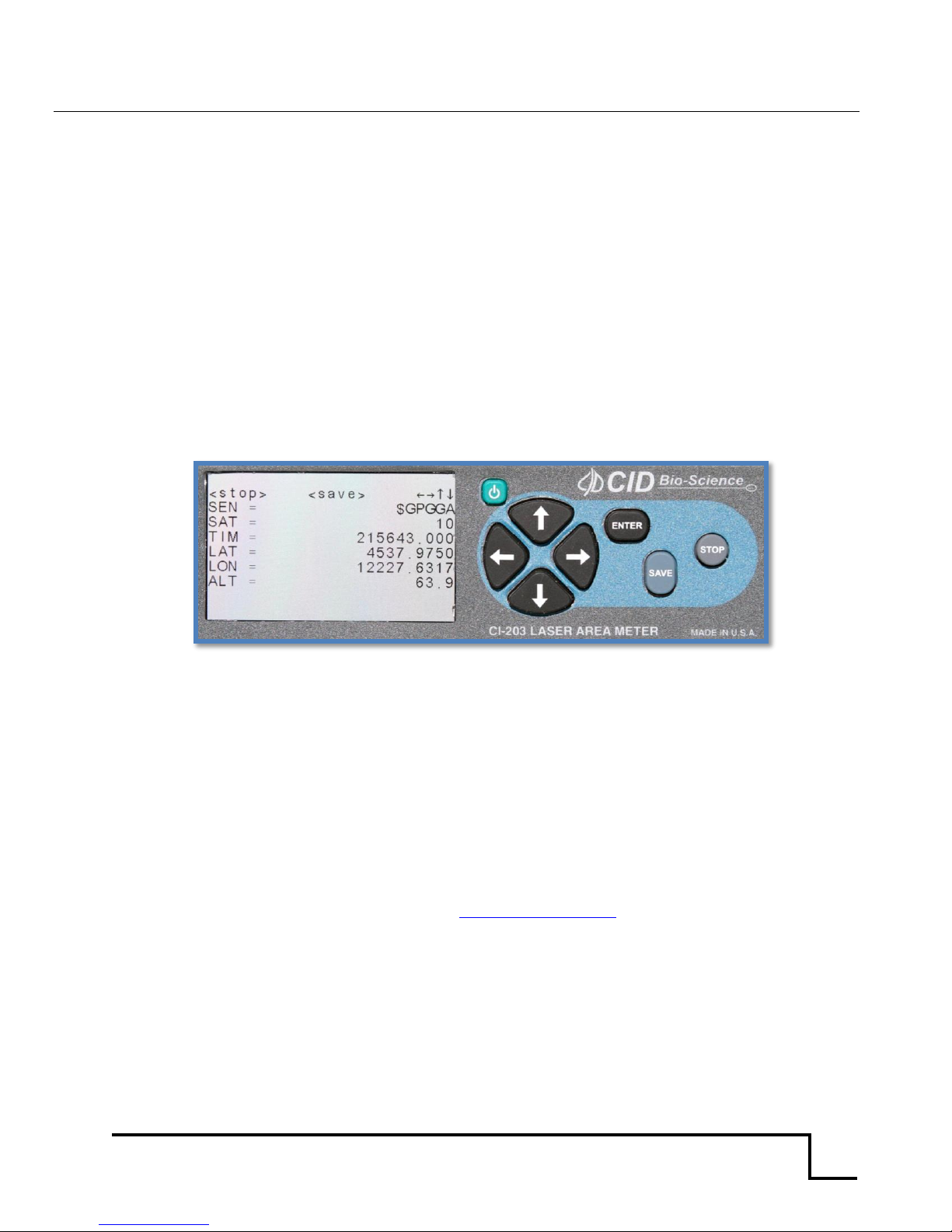
The new CI-203 has a built-in GPS system which can relay the longitude, latitude and altitude of the
instrument when performing measurements. The figure below shows the GPS menu display. The GPS
uses GMT or Greenwich Mean Time for a standardized time. The GMT is displayed as the time (TIM)
on the GPS menu and is synchronized with minute and second alignment. Often when the instrument
is turned on indoors, the latitude, longitude and altitude will read “no fix.” This occurs when no
satellite signal can be obtained by the instrument. Powering up the CI-203 outdoors will correct this
problem and allow latitude, longitude and altitude readings to be taken along with leaf measurements.
Figure 5. CI-203 GPS menu
Other View Menu Options
Besides viewing saved data or files, you can also check on the voltage, battery power remaining, GPS
location, time stamp (time and date) and the properties of the SDcard from the CI-203 View Menu.
Use the UP/DOWN arrow to highlight the desired setting and then press the RIGHT arrow to make a
selection. Press the LEFT arrow key to go back to the View Menu. Press STOP to go back to the Main
Menu.
The View Voltage screen shows the current voltage of the instrument and the View Battery displays
the percent battery life left. If any of these numbers are rapidly changing after the instrument has
warmed up, please contact technical support at [email protected].
The View Flash option is only accessible by CID Bio-Science technicians.
The View Time screen displays the current time on the instrument. The View GPS screen displays the
current GPS values for latitude, longitude, altitude and indicates the number of satellites currently
connected to. Press the UP/DOWN arrow to display more GPS information. The GPS may read “nofix”
if the instrument is located indoors and cannot connect with a satellite.
The View SDcard screen indicates if an SDcard is present in the unit. If no SDcard is in the instrument,
or if the SDcard is not fully inserted, “no” will appear in the display next to SDcard.
Page 16
CI-203 Instruction Manual rev. 8/9/2016
1554 NE 3rd Ave, Camas, WA 98607, USA
Phone (360) 833-8835 Fax (360) 833-1914 [email protected] http://www.cid-inc.com
14
FILE MENU
The File Menu is accessed by highlighting “File” on the Main Menu and pressing the RIGHT arrow key.
Here, the user can manipulate files on the CI-203, with options to clear, delete, create and open files.
The CI-203 uses an SDcard to store all measurements. This means the user is able to create, clear and
delete any measurement file. The instrument uses a regular FAT32 file system to access stored data.
To view data on a computer, simply connect the instrument to the USB port on the computer with the
USB cable included or insert the SD card into the computer’s SDcard reader. The computer should
automatically detect the SDcard as a new storage device and mount the drive so that measurement
data will be accessible by any computer application. When the user creates a file to store data on the
computer, the same file name created on the SDcard will be used, with the file extension ‘.img’. The
image file is used to store synthesized images for each measurement.
Clear a File
Pressing the RIGHT arrow key when ‘Clear’ is highlighted on the display allows the erasure of the file
contents without changing its name or its set-up. This feature is useful if it is necessary to do a
number of similar measurements. The user can take these measurements to a particular file, copy the
results, clear the file, and be ready to take a new set of measurements using that same file.
With ‘Clear’ selected, the RIGHT arrow key will take you to the View Files menu. Use the UP or DOWN
arrow keys to select the file to clear. Press the RIGHT arrow key to clear the file. The display will
indicate “Done!” when the file contents are erased, and you will be returned to the View Files menu.
Press STOP to go back to the File Menu.
Delete a File
With ‘Delete’ selected, the RIGHT arrow key will take you to the View Files menu. Use the UP or DOWN
arrow keys to select the file to delete. Press RIGHT arrow key to delete the file. The display will
indicate “Done!” when the file is deleted, and you will be returned to the View Files menu. Press STOP
to go back to the File Menu.
View Files
File00 15
Greg17 23
Page 17
CI-203 Instruction Manual rev. 8/9/2016
1554 NE 3rd Ave, Camas, WA 98607, USA
Phone (360) 833-8835 Fax (360) 833-1914 [email protected] http://www.cid-inc.com
15
Create a File
Press the RIGHT arrow when “Create” is highlighted on the display to get the unit into the create files
mode. The top line of the screen will read “Name” on the left, and a file name (e.g. “file00”) on the
right. The bottom line will read “enter” at the left, “erase” at the center, and the left/right arrows
appear at the right.
Name: file00
enter erase
NOTE: The STOP key can be pressed at any time to abort the file creation process and to
return to this point.
Pressing the arrow keys will allow the user to enter an alpha or numeric selection for a six-character
file name. The RIGHT/LEFT arrow keys select which character in the file name to edit and the
UP/DOWN arrow keys are used to choose a character. The chart below lists the available characters.
! " # $ % & ' ( ) * + , - x / 0 1 2 3 4 5 6 7 8 9 : ; < = > ? ] [ ¥ ^ _ @
A thru Z in uppercase
a thru z in lowercase
Pressing the ‘SAVE’ key while editing a filename deletes that character position. Note that the cursor
position is represented by a reverse character display. Characters cannot be inserted into an existing
file name.
Once the desired filename has been selected, press ENTER. The next screen toggles through the test
names with the RIGHT and LEFT arrow keys and toggles ‘yes’ and ‘no’ with the UP and DOWN arrow
keys. This has no effect on the measurements; all parameters are tested on every measurement.
The user should just press enter to bypass this screen.
Should the file name be identical to another file name, the instrument will display the message
“duplicate name” and “enter” on the two top lines of the display.
The CI-203 will save all parameters for each measurement (width, length, perimeter, area, aspect
ratio, and shape factor) on the SDcard. Use the LEFT/RIGHT arrows to scroll through the parameters
and the UP/DOWN arrows to include or exclude parameters. Once finished creating the file name and
setting parameters, press the ENTER key. The file confirmation screen will appear. Press ENTER
again for confirmation to create the file, or press STOP to abort the process.
Test10 Create
<enter> <stop>
duplicate name
<enter>
Page 18
CI-203 Instruction Manual rev. 8/9/2016
1554 NE 3rd Ave, Camas, WA 98607, USA
Phone (360) 833-8835 Fax (360) 833-1914 [email protected] http://www.cid-inc.com
16
Transfer Data to a Computer
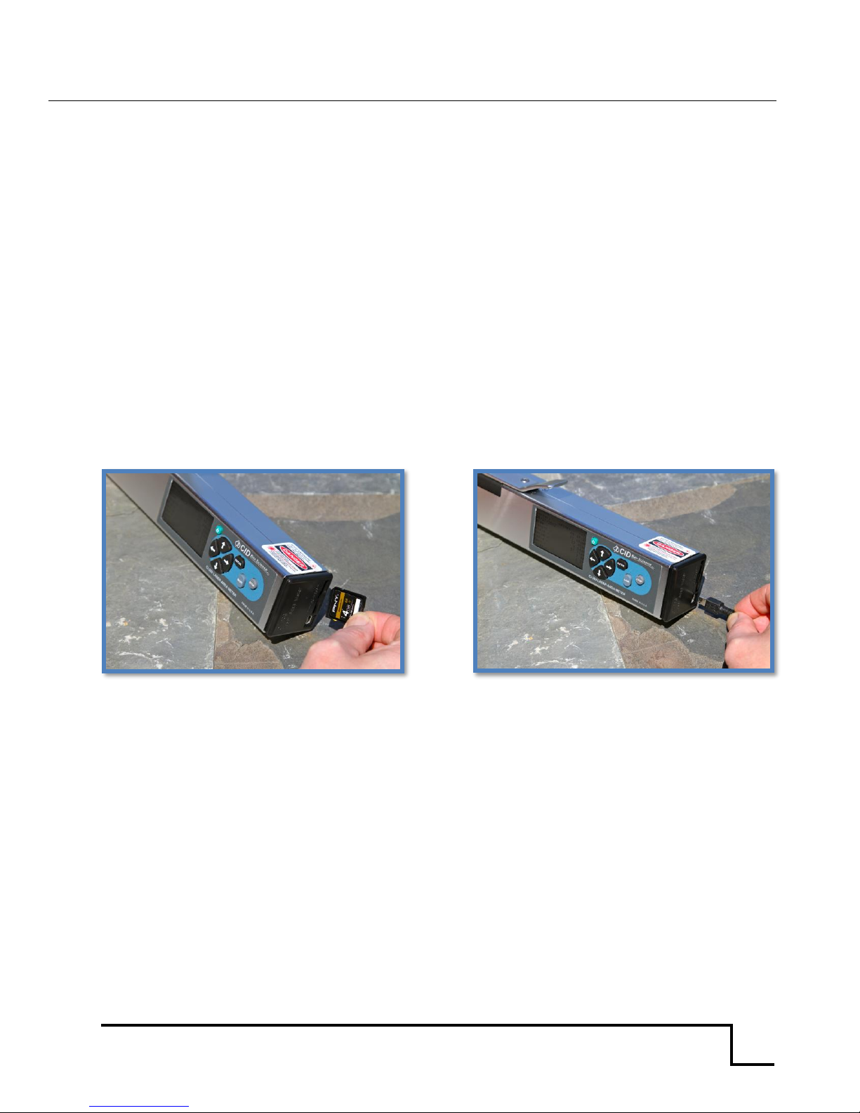
To view the collected data on a computer, the user can use the supplied USB cable and connect the
instrument to the USB host (computer). Alternatively, the user can remove the SDcard and view
files/data on the SDcard on another computer. Lastly, the user can wireless transfer files if it was
equipped with Wireless SD memory card (see below for further instructions). The ‘Dump’ command is
used to close the last file accessed before transfer. To do this, select ‘Open’ from the File Menu screen
and press the RIGHT arrow key. This will take the user to the View Files menu, and the last accessed
file will be highlighted. Press RIGHT arrow again and that file will be closed and ready for transfer.
Once the instrument data source is connected to the computer, it is strongly recommended that the
user copy and resave the files and images to the hard drive of the computer. The computer
application used to view the files can also be used to resave them. It is recommended that the user
does not work from the original file on the SDcard after the measurement has been made, because if
any changes are made to the original file, it can break the alignment of the file causing error and
possible data loss.
In order to keep the file system in sync, perform any editing or further calculations on the copied file
saved to the computer hard drive. Do not edit the file directly on the instrument.
Figure 6. SDcard and USB cable connection for CI-203
Do not connect the USB cable to the instrument and the computer while performing measurements. If
the user tries to operate the instrument through the computer, the files are subject to becoming out of
sync, breaking alignment and causing errors in the files. This can also lead to problems with saving
data.
If an error occurs in a specific data file, it can be deleted and created again. Go to the File Menu on the
instrument; clear the file where the error has occurred. If the file has been transferred to the
computer, delete it on the computer also. Once the corrupted files have been deleted, create the file
again (if it has been properly deleted, the same file name can be used) and re-take the measurement.
Page 19
CI-203 Instruction Manual rev. 8/9/2016
1554 NE 3rd Ave, Camas, WA 98607, USA
Phone (360) 833-8835 Fax (360) 833-1914 [email protected] http://www.cid-inc.com
17
Wireless Transfer
The following instructions are for the Toshiba Wireless SD memory card W-03 that came included
with your CI-203
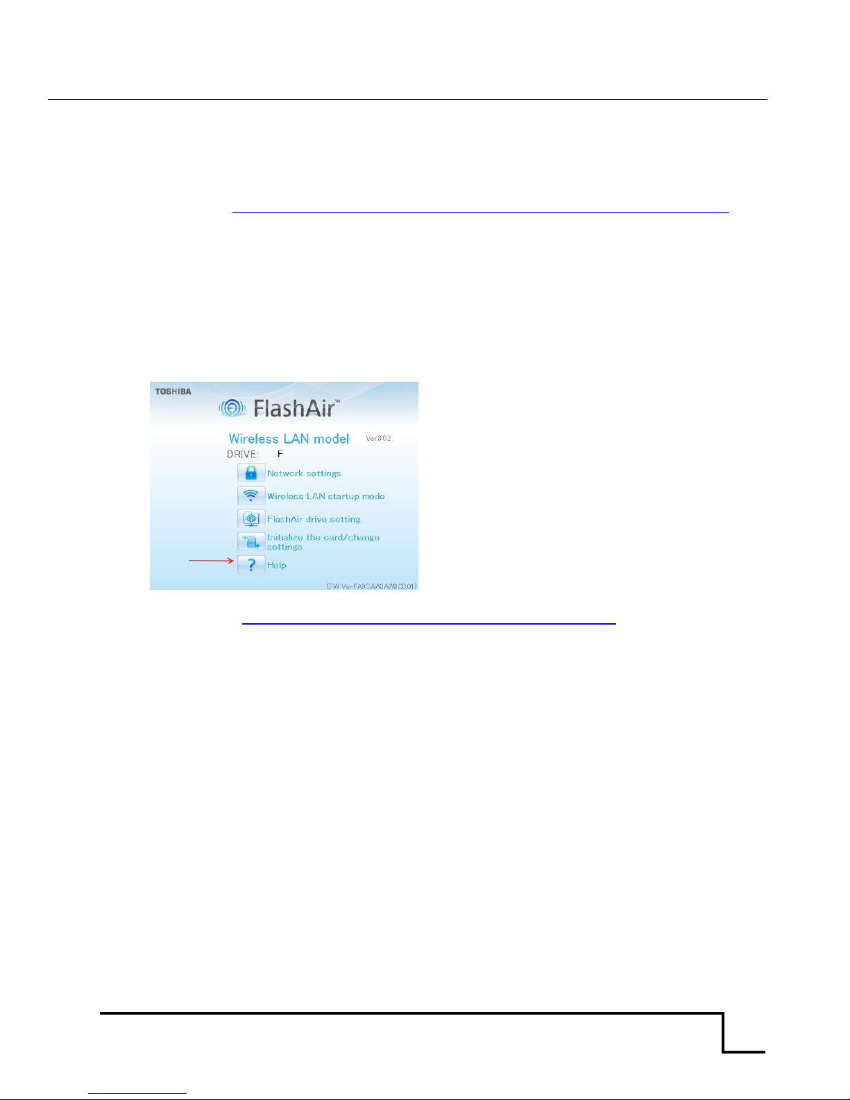
1. Install FlashAir™ Wi-Fi card software appropriate to the SD card.
a. Visit https://www.toshiba.co.jp/p-media/english/download/wl/software02.htm to
download the software for configuring the Wi-Fi card and obtain vendor operation
instructions.
2. Insert the Wi-Fi card onto a personal computer (PC).
3. Open the “FlashAirTool” on your PC to configure the SD card.
4. Follow the configuration instructions prompted by the “FlashAirTool”. It is recommended to
map the Wi-Fi card as a drive as prompted by the FlashAirTool. This creates a shortcut on
your desktop to easily access your files from your device.
5. For additional guidelines, access the “Help” menu inside the “FlashAirTool” software.
For more information on the Toshiba FlashAir™ W-03 Wireless SD Memory Card, contact the
application vendor at https://www.toshiba.co.jp/p-media/wwsite/contact.htm,
Page 20
CI-203 Instruction Manual rev. 8/9/2016
1554 NE 3rd Ave, Camas, WA 98607, USA
Phone (360) 833-8835 Fax (360) 833-1914 [email protected] http://www.cid-inc.com
18
How Data Appears in a File
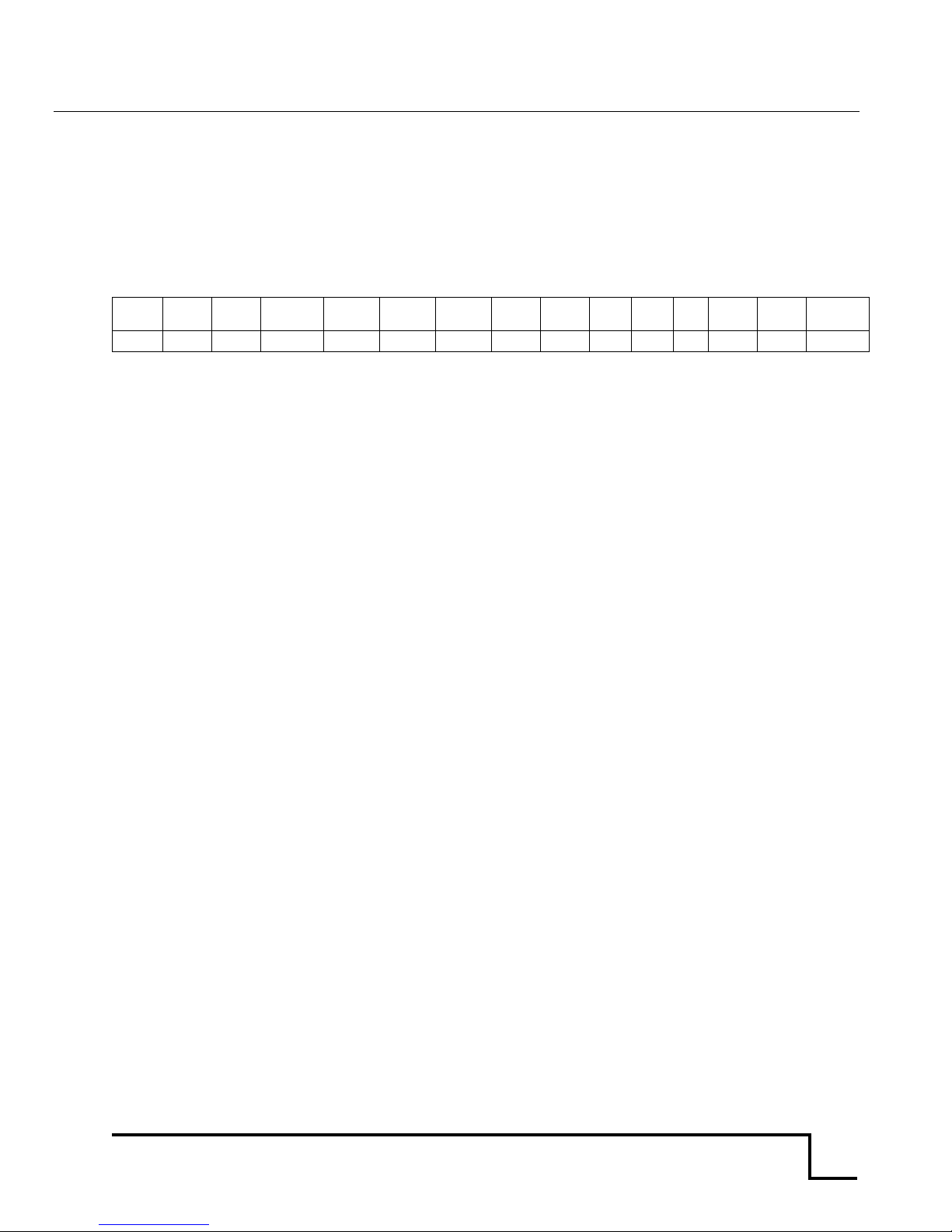
Data saved by the instrument during measurement can be viewed later on a computer using a
spreadsheet program. Fifteen different columns of data will be seen in the downloaded or transferred
file, including the date (month/day/year), time of measurement (hour/minute/second), area, length,
width, perimeter, ratio, factor, voids, latitude, longitude and altitude. Three columns are related to the
new GPS function of the instrument and the columns for file start location, length, and pixel lines for
the images (i.e. these columns do not relate directly to leaf measurements).
Date
Time
Area
Length
Width
Perim
Factor
Ratio
Void
Lat
Lon
Alt
Rec_
Off
Rec_
Len
Pix_Len
How to Work With or Manipulate Data Files
The CI-203’s removable SDcard makes it easy to work with and manipulate data files after taking
measurements. Remove the SDcard from the CI-203 after powering off the instrument. Insert the card
into a computer. Copy and save the files from the SDcard onto the hard drive of the computer. Open
the files saved on the hard drive to start any data manipulation or management work. Saving the data
files in this manner and not working directly from the SDcard will help to prevent the corruption of
the data on the SDcard and the instrument. Once files are copied and saved to a hard drive, they can
be deleted from the SDcard.
Do not edit files directly on the instrument. Doing so may corrupt data and cause loss of files.
Page 21

CI-203 Instruction Manual rev. 8/9/2016
1554 NE 3rd Ave, Camas, WA 98607, USA
Phone (360) 833-8835 Fax (360) 833-1914 [email protected] http://www.cid-inc.com
19
THEORY OF OPERATION
Overview of the Parts of the Instrument
The CI-203 consists of a number of sub-systems. It has a laser width scanner that is capable of
measuring the width of an object in its objective 500 times a second to a resolution of 0.1 mm. It has a
roller length measuring system that can measure length steps of 1 mm. The entire instrument is
controlled by a microcomputer system that allows the user unparalleled flexibility in configuring the
instrument to make measurements accurately, easily and quickly.
The Width Scanner
When the instrument is in the scanning mode, a rotating mirror causes a laser beam to scan across the
objective 500 times a second. This beam is reflected off the special surface of the measuring arm and
received by a light sensor inside the unit. The level from this sensor is compared to a threshold. The
output of the “comparator” is fed to a counter, which is sampled at intervals during the width
scan. This count is used to calculate the width measurement for each scan.
The Length Step (Roller System)
The instrument includes a roller under the measurement arm that determines length
information. Each time the object being measured travels 1 mm, the computer is alerted, and
integrates the width and length scan information into the various parameters being measured.
Computing the Parameters
The CI-203 measures only two parameters directly: width and length. From these it derives area,
perimeter, aspect ratio, and shape factor from each scan.
Each time the meter senses the leaf has progressed 1 mm, the computer will check if the width
reading is a non-zero value.
If the width measurement is non-zero, the computer takes the following actions:
The width measurement is added to the area accumulator.
If the width measurement is greater than the currently stored maximum width, the maximum width is
updated.
Page 22

CI-203 Instruction Manual rev. 8/9/2016
1554 NE 3rd Ave, Camas, WA 98607, USA
Phone (360) 833-8835 Fax (360) 833-1914 [email protected] http://www.cid-inc.com
20
The perimeter increment is calculated and added to the perimeter accumulator. This perimeter
increment is calculated using the function:
If the width measurement reaches zero and the instrument is not operating as part of the conveyer
attachment, the measurement stops and is displayed.
Computing Aspect Ratio and Shape Factor Information
Aspect ratio and shape factor information can be easily determined from other calculated values.
These derived quantities are not stored but calculated, whenever necessary, for the purposes of
display or data dumping. The calculations used are shown below.
Aspect ratio is the ratio of the leaf length to its maximum width. It can be calculated from the
equation:
Shape factor is the ratio of the leaf area to the leaf perimeter, corrected so that the shape factor of a
circle is equal to one. It can be calculated from the equation:
Page 23

CI-203 Instruction Manual rev. 8/9/2016
1554 NE 3rd Ave, Camas, WA 98607, USA
Phone (360) 833-8835 Fax (360) 833-1914 [email protected] http://www.cid-inc.com
21
CARE AND CLEANING
Treat the CI-203 as any other fine optical instrument. Keep the lens clean and free from scratches.
When not in use, keep the instrument in its protective case. Use only a mild detergent and damp cloth
to clean the exterior areas of the instrument. Use a high quality lens cleaning cloth to clean the
window. Do not submerse or use an overly wet cloth to clean the instrument. Do not drop the
instrument.
For an extended storage period, we recommend storing the instrument in a cool and dry place.
Charging the Battery
The batteries are Nickel Metal Hydride (NiMH). While they can be recharged hundreds of times, they
do not have the shelf life of an Alkaline battery. They will need to be recharged even if the unit has not
been used for a period of time. Any time that the battery indicator shows less than 30% charge, the
instrument should be recharged. NiMH batteries have a tendency to hold optimum voltage for as long
as possible, then drop off very quickly. To charge the battery, connect the charger output to the
battery port on the instrument (the same port you would use to send data) for at least 14 hours.
Batteries should be fully charged soon thereafter. Storing a battery in a discharged state could
permanently damage it.
Taking Care of the Rubber Roller in the CI-203
When the rubber roller in the CI-203 gets dirty, it will stick or fail to spin as smoothly as it should. As a
result, certain sections of the leaf will be scanned twice or more causing the measurement to not be
repeatable. To correct this problem, the user should take the roller out. To remove the roller, press
the roller towards the hand-held end, then gently lift it up from the hand-held end while pulling it out
in the same direction.
The rubber roller may not be snug in its place, or it may shift out a little so that the scanning result is
not linear. The user needs to make sure that the roller is snug in place to perform measurements
correctly.
Page 24

CI-203 Instruction Manual rev. 8/9/2016
1554 NE 3rd Ave, Camas, WA 98607, USA
Phone (360) 833-8835 Fax (360) 833-1914 [email protected] http://www.cid-inc.com
22
TROUBLESHOOTING
Technical Support
If you have a question about the CI-203 features and functions, first look in the CI-203 Instruction
Manual. If you cannot find the answer, you can access troubleshooting information and the CI-203
Product Support Forum at:
http://www.cid-inc.com/leaf-area/ci-203-support.php
Questions can also be directed to a Technical Support Representative located in your country. CID
Bio-Science, Inc. is committed to provide customers with high quality, timely technical support.
Technical support representatives are to answer your technical questions by phone or by e-mail at:
CID Bio-Science, Inc.’s contact information:
CID Bio-Science, Inc.
1554 NE 3rd Ave
Camas, WA 98607 USA
Phone: 800-767-0119 (U.S. and Canada)
360-833-8835
Fax: 360-833-1914
Internet: http://www.cid-inc.com
E-mail: [email protected]
Customer Service
Customer Service Representatives answer questions about specifications and pricing, and sell
all of the CID Bio-Science, Inc. products. Customers sometimes find that they need CID Bio-Science,
Inc. to upgrade, recalibrate or repair their system. In order for CID Bio-Science, Inc. to offer these
services, the customer must first contact us and obtain a Return Merchandise Authorization (RMA)
number. Please contact a customer service representative for specific instructions when returning a
product.
Page 25
CI-203 Instruction Manual rev. 8/9/2016
1554 NE 3rd Ave, Camas, WA 98607, USA
Phone (360) 833-8835 Fax (360) 833-1914 [email protected] http://www.cid-inc.com
23
Error Message
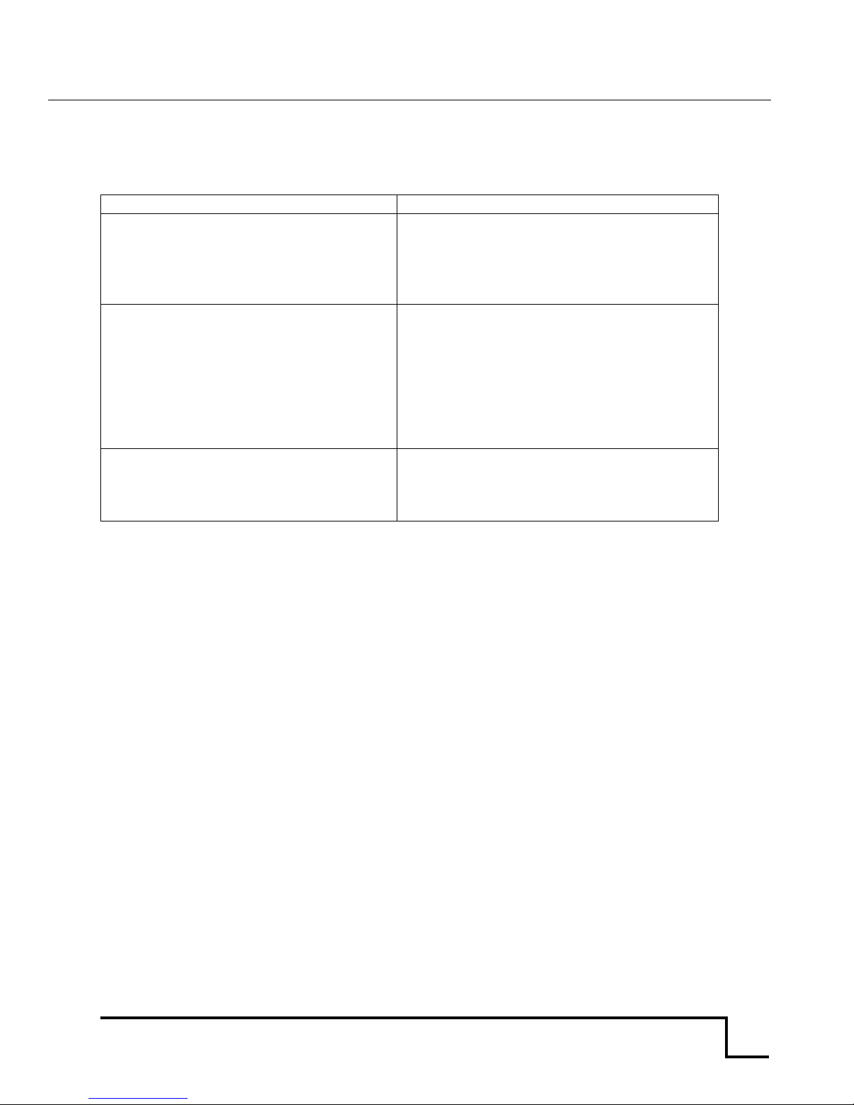
The following error messages should rarely appear in normal operation. If they do appear, see
Appendix III and follow the steps to restore the setup data.
MESSAGE:
MEANING:
Bad NVRAM Checksum <start>
Instrument setup data has been lost. Pressing
the START key will restore default values and
display the message “NVRAM Defaults Saved”.
Measurement will not be accurate until recalibrated (See Appendix III).
Leaf Not Cal’ed <start>
Root Not Cal’ed <start>
Conveyor Not Cal’ed <start>
Conveyor, Leaf or Root mode selected when
the power turned on has not been calibrated.
Pressing the START key will dispatch the
message and allow the instrument to operate,
but measurements will not be accurate until
calibrated. This message will appear every
time the power is turned on, until the
instrument is calibrated.
Bad EPROM Checksum
EPROM containing instrument firmware has
bad checksum, indicating it has failed. The
instrument will not operate with a bad
EPROM.
Page 26

CI-203 Instruction Manual rev. 8/9/2016
1554 NE 3rd Ave, Camas, WA 98607, USA
Phone (360) 833-8835 Fax (360) 833-1914 [email protected] http://www.cid-inc.com
24
Frequently Asked Questions
1. Where do I download the most current version of CI-203 software?
The latest version of software and the driver can be downloaded at www.cid-
inc.com/Software/CI-203. This webpage has links for CI-203 transfer software, USB
driver and firmware downloads.
2. How do I turn the CI-203 off if the instrument is hung-up and the display is frozen?
Connect the instrument to the computer with the USB cable. This should cause the
freeze-up to go away and you will be able to restart the instrument.
3. Why is the instrument getting hung up or stuck stabilizing?
The CI-203 requires that you create at least 2 files before taking a measurement. To
create a file, go to the File<Create menu and use the up/down arrows to set the file
name to what you desire. Then, save the file name. If the unit does not have a file
created, it will not be able to save measurement data and may not work properly.
4. How do I clean the CI-203?
Use a soft, clean lint-free cloth to wipe down the scan glass under the arm. Make sure
the scan glass is free from particles and debris. You can use canned air to remove any
debris on or under the glass by gently passing the air across the scan window.
5. How do environmental changes affect the CI-203?
The CI-203 can be affected by rapid changes in humidity and temperature, such as
when moving from an air conditioned vehicle to a hot field habitat or greenhouse. With
the rapid shift in the environment, there is a small chance condensation may form
causing a temporary freeze-up of the CI-203. To remedy this, it is advised to wrap the
instrument in a plastic bag and allow it to equilibrate with the ambient temperature
when changing the instrument's environment. If the environmental change is small the
user should not need to allow the unit to stabilize as long and should not incur a unit
freeze-up.
6. Why can’t I open all the files on the SDcard?
There are two files transferred for each data file. One holds the spreadsheet and
length/area/width information. The other file is an image file which holds the image of
the scanned leaf—what the user can see on the CI-203 display after a measurement is
made. We are working on a software that allows the user to see this image after the
initial measurement. For now, the .img file holds the information that the data file
shows in numbers. Also, if there is no data in a file, the file name will still appear on the
SDcard.
7. What are the Rec_Off, Rec_Len and Pix_Len data columns?
The last three columns in the data sheet (Rec_Off, Rec_Len and Pix_Len) hold image
rendering information. This information does not affect the leaf measurement, but if
the user changes any data in these columns and saves it to the SDcard, it can corrupt
the data file. Rec_Off is for image offset information and Rec_Length has length of
image information.
Page 27

CI-203 Instruction Manual rev. 8/9/2016
1554 NE 3rd Ave, Camas, WA 98607, USA
Phone (360) 833-8835 Fax (360) 833-1914 [email protected] http://www.cid-inc.com
25
8. What do I do if the leaf length isn’t accurate?
If your CI-203 or CI-203CA is not measuring length accurately, you may be losing the
length value for either or both of the following reasons:
a) You may not be pulling the longest portion of the leaf exactly perpendicular to the
roller.
b) You have missed the very start of the leaf. Only the longest petioles allow for
complete leaf measurements.
These factors should be considered by the researcher and necessary adjustments
made. The area measurement is typically more significant and more accurate than the
length measurement, because it is based on two different vectors and sensing
mechanisms. Area, however, is still subject to the 2 potential sources of error listed
above, though to a lesser extent.
If you think your instrument is not measuring length accurately, a photo of the leaf or a
video of the measurement would help determine whether the technique or the
instrument is introducing the error. Please email [email protected] for help.
9. How do I transfer files off the CI-203?
There are two commonly used ways to transfer data from a CI-203 with an SDcard.
The first is to connect the CI-203 to a computer using the USB cable. Typically, the
computer’s “Autoplay” will pop-up with a message asking what to do with the
“Removable Device.” Choose “Open folder to view files.” Open and re-save the files off
the SDcard before making any changes. The second transfer involves simply taking the
SD card out of CI-203 and inserting in a computer’s SDcard reader. Transfer and re-
save the files off the SDcard before making any changes/edits.
Neither of these methods of transferring the data from the CI-203 require that the CI203 driver be installed on a computer. The data transfer is designed to be quick and
easy with the SDcard, involving NO software or drivers. ALWAYS SAVE THE FILE ON
THE COMPUTER BEFORE MAKING ANY CHANGES. DO NOT EDIT FILES ON THE
SDCARD.
10. How do I remove particles from the CI-203 Conveyor?
There are two small black caps on either side of the conveyor drum. These caps can be
removed, allowing a cloth to be passed through the conveyor drum. Any loose debris
or particles can be vacuumed out or otherwise removed. The drum can be wiped with
a clean cloth to remove any smudges.
Page 28

CI-203 Instruction Manual rev. 8/9/2016
1554 NE 3rd Ave, Camas, WA 98607, USA
Phone (360) 833-8835 Fax (360) 833-1914 [email protected] http://www.cid-inc.com
26
CI-203 Firmware Upgrade
Occasionally, firmware updates are released to correct bugs or problems found. The firmware of the
instrument is tied to the hardware and serial number of the unit. All firmware updates are
categorized by serial number, so be sure to check that you are installing the proper firmware file
(.bin).
To begin the most recent update, there are two files on the CD or that need to be downloaded at:
http://www.cid-inc.com/leaf-area/ci-203-software.php
1. ci-203-ver-4.17.bin October 22 2012: Binary code for CI-203.
2. DL203V1003.exe (executable file) 1107kB 22June2011. Download code to
CI-203.
Download both files into one directory on the computer that has the CI-203 drivers installed.
Turn on the instrument and plug in the USB cable, run DL203V1003.exe and select File, then
select Open, then select ci-203-ver-4.17.bin.
HOLD POWER BUTTON DOWN will be displayed. You must hold the power button on the CI-
203 until the unit switches from normal mode to boot loader mode.
The transfer may take several minutes. Please make sure you download all your data files and
erase all files on the CI-203 before updating the firmware.
Remember to create a file to save measurements into after updating the firmware version.
CHECK THAT THE SERIAL NUMBER HAS 3.01 FOR THE MIDDLE DIGITS TO BE COMPTABILE WITH VERS 4.17
(ex: 203-3.01-11xxx)
Installing the wrong firmware version can result in permanent damage to the microprocessor and control
board! Please make sure to install the correct firmware version for your CI-203, based on the serial number.
CI-203 Driver Installation
There are two driver files (CI-203.inf and CI-203.cat) on the CD or that need to be downloaded at:
http://www.cid-inc.com/leaf-area/ci-203-software.php
If you need to install the CI-203 USB drivers on a Windows computer, you can use the software that
was sent with the CI-203 or go to:
http://sourceforge.net/projects/libusb-win32/files/libusb-win32-releases/1.2.4.0/libusb-win32-bin-1.2.4.0.zip/download
The libusb-win32-bin-1.2.4.0.zip should be unzipped in your Documents folder and the .inf file CI-
203.inf and the .cat file CI-203.cat should be saved in the resulting libusb-win32-bin-1.2.4.0 folder in
your Documents folder. Plug the instrument in and browse to the libusb-win32bin-1.2.4.0 folder in
the New Hardware Found wizard in order to install the drivers.
Page 29

CI-203 Instruction Manual rev. 8/9/2016
1554 NE 3rd Ave, Camas, WA 98607, USA
Phone (360) 833-8835 Fax (360) 833-1914 [email protected] http://www.cid-inc.com
27
Re-computing the CI-203 Parameters
This procedure should be carried out whenever the CI-203’s threshold settings are changed or if the
instrument isn’t measuring accurately. Re-computing the parameters will recalculate the effects of
any changes made on the other parameters.
1. From the "Measure" menu, press the LEFT and RIGHT arrow keys at the same time.
2. Hold the buttons until the motor begins to spin. The motor should spin for about 4 seconds.
3. Do this twice by pressing the LEFT and RIGHT arrow keys simultaneously again and making
sure that the motor spins up.
4. Take a test measurement and try to determine if the Length or Width readings need
adjustment. Are the readings too high or too low?
Page 30
CI-203 Instruction Manual rev. 8/9/2016
1554 NE 3rd Ave, Camas, WA 98607, USA
Phone (360) 833-8835 Fax (360) 833-1914 [email protected] http://www.cid-inc.com
28
APPENDIX I: OPERATING THE CI-203 LASER LEAF AREA METER
WITH THE CI-203CA CONVEYOR ATTACHMENT
This appendix explains how the CI-203 is installed in the CI-203CA, and differences in operations
between the CI-203 alone and used with the CI-203CA.
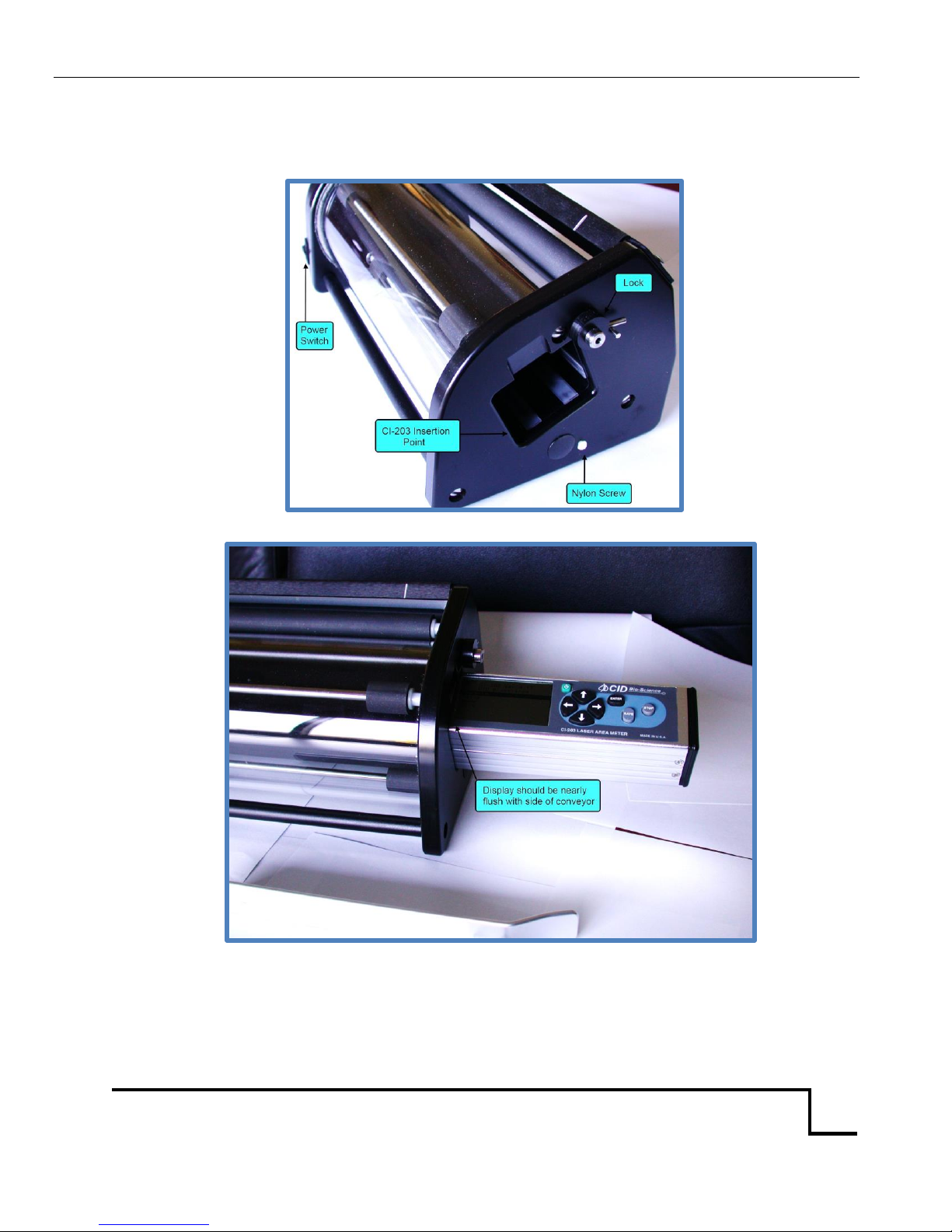
IMPORTANT NOTE: for shipping and transportation purposes only, the glass roller needs to be
tightened down. There is a nylon screw on one side of the conveyor (see Figure 8) to hold the glass
roller in place. Loosen screw for use; tighten the screw for shipping and transportation. For the
conveyor to operate properly, loosen the screw.
Hardware Setup
To use the CI-203 with the CI-203CA, the CI-203 must be installed in the CI-203CA. Do not turn the CI203 on from its keypad. To install the CI-203CA, follow these steps:
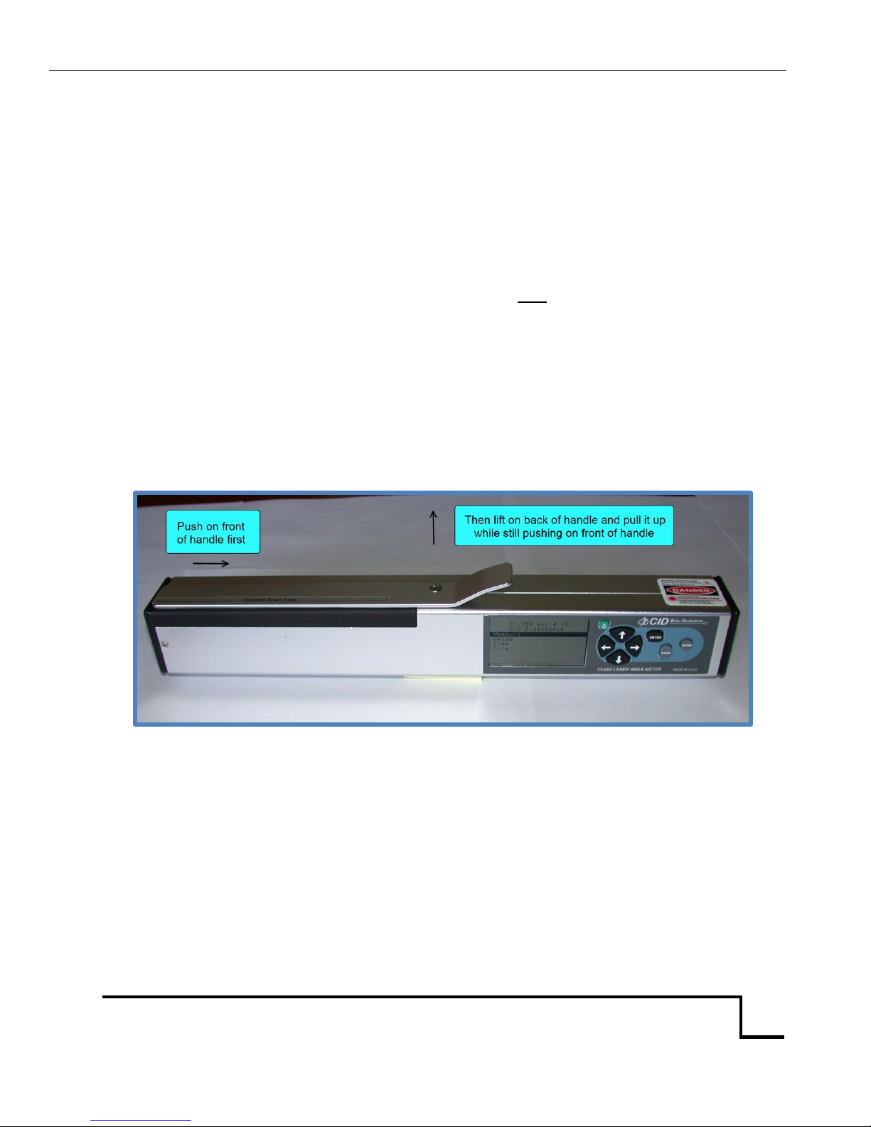
Figure 7. Illustration of how to remove the arm.
1. Remove the roller arm on the CI-203 Laser Leaf Area Meter by pushing the front section of the
arm slightly back toward the display and lifting it out (see Figure 7). Orient the CI-203 so that
the display will be lined up with the notch on the housing of the CI-203CA. Once this is done,
insert the CI-203 all the way into the hole in the side of the CI-203CA. Confirm that the CI-203
is inserted into the CI-203CA all the way by verifying that the housing on the CI-203CA covers
the left edge of the display. Once this is done, rotate the Lock lever on the CI-203CA counter-
clockwise to secure the CI-203.
Page 31
CI-203 Instruction Manual rev. 8/9/2016
1554 NE 3rd Ave, Camas, WA 98607, USA
Phone (360) 833-8835 Fax (360) 833-1914 [email protected] http://www.cid-inc.com
29
The white nylon screw on the right side of the conveyor is used to prevent shipping damage. It should
be loosened when using the conveyor.
Figure 8. Insert the CI-203 into the housing (hole) in the side of the CI-203CA.
Figure 9. Insert the CI-203 until flush with side of conveyor.
Page 32
CI-203 Instruction Manual rev. 8/9/2016
1554 NE 3rd Ave, Camas, WA 98607, USA
Phone (360) 833-8835 Fax (360) 833-1914 [email protected] http://www.cid-inc.com
30
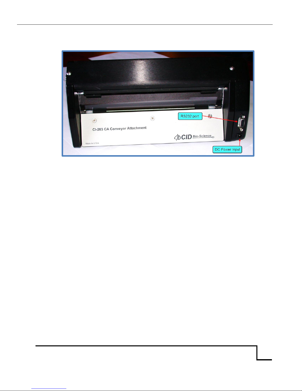
2. Connect a suitable 9V DC power source, such as the AC adapter supplied by CID Bio-Science,
Inc., to the power input socket on the back of the CI-203CA.
Figure 10. The RS232 port and the Power Jack of the CI-203CA.
3. Press the power switch on the CI-203CA (see Figure 10) to the ON position.
Note: The CI-203/CI-203CA combination must be turned on with the switch for the CI-203CA in order
to take measurements!
Anytime a CI-203 is reinserted into the conveyor, or if any problems are encountered, press the right
and left buttons simultaneously. This will match the conveyor to the CI-203. It will run for a few
seconds, then turn off. Repeat this twice.
Page 33
CI-203 Instruction Manual rev. 8/9/2016
1554 NE 3rd Ave, Camas, WA 98607, USA
Phone (360) 833-8835 Fax (360) 833-1914 [email protected] http://www.cid-inc.com
31
Measure
When the CI-203 is used with the Conveyor Attachment, it is assumed the user wishes to measure a
large number of leaves all in one batch. Because of this, the instrument does not stop after each
measurement to allow the user to preview and make a “save/no save” decision. Rather, the
instrument will take measurements and automatically save them until the user stops the conveyor
process.
In the Measure mode, the top line of the screen will read “Measure” on the right and the name of the
file on the left. The bottom line of the screen will read “<start>” on the left and four direction arrows
on the right.
File00
<start>
Measure
←→↑↓
The options are:
1. To select another mode with the ↑ or ↓ keys.
2. To select another file (if there is more than one) with the ← or → keys.
3. To take a set of measurements.
To begin a set of measurements, select a file to write to and press the Enter key. The conveyor, scan
motors, and the laser beam will come on when the Enter key is pressed. The display will read
“Measure” on the upper left corner with the name of the file in the upper right corner. The display will
read “Stabilizing” on the bottom line for 0.25 seconds while the instrument adjusts the scan rate.
When the instrument is ready to start taking measurements, the bottom line of the display will read
“Measuring”. Begin feeding leaves into the conveyor. Once the first leaf has been measured, and for all
subsequent leaves, the instrument will display the file name in the upper left of the display and the
sequence number in the upper right. The lower lines of the display will show the area measurement
parameters for the last leaf measured.
NOTE: Because of the amount of information displayed on this screen, the CI-203 cannot display
prompts in this mode.
To stop taking measurements, press the STOP button or let the machine time out. The instrument will
turn off the laser, conveyor, scan motors and laser and will return to the Measure menu. To view the
measurements, see the View Menu section of this manual.
Page 34

CI-203 Instruction Manual rev. 8/9/2016
1554 NE 3rd Ave, Camas, WA 98607, USA
Phone (360) 833-8835 Fax (360) 833-1914 [email protected] http://www.cid-inc.com
32
CI-203 Conveyor Calibration with CI-203
A new CI-203 needs to be calibrated to the conveyor. Put the 203 in the conveyor, plug the conveyor
in and turn on the conveyor. If you have more than 1 CI-203 or update the firmware, the instrument
and conveyor should be re-calibrated together. The CI-203 should power on and indicate it is in
conveyor mode.
1. From the main menu, highlight the Measure option and press the right arrow button.
2. From the Measure menu, press the left and down arrow keys simultaneously to calibrate the
length. Let the conveyor run for about 30 seconds, then press the stop button.
3. Next, from the Measure menu, press the left and right arrow keys simultaneously. You should
hear the CI-203 motor spin up for about 4 seconds, and then shut off. Do this twice.
4. Next, go to Setup<Scanner<Adjustment<Scan Width selection and place a piece of paper with a
known width in the conveyor under the top roller so the unit will measure it. Press the right
arrow key. The CI-203 motor will spin up, but not the conveyor.
5. By pressing the up and down arrow buttons, adjust the width measurement to the width of the
known paper. You should set the scan width to the known papers width minus 0.3mm.
6. Save your changes.
7. Go to the Measure menu and have the unit measure. Test out the unit to see how the
calibration affected it.
Page 35

CI-203 Instruction Manual rev. 8/9/2016
1554 NE 3rd Ave, Camas, WA 98607, USA
Phone (360) 833-8835 Fax (360) 833-1914 [email protected] http://www.cid-inc.com
33
Setup Instrument
There are some operating modes which are not available to the user when the CI-203CA is being used.
The user does not have access to the menu options for the CI-203CA when the CI-203 is being used.
The threshold setting is available only when the CI-203CA is being used (at the same time, the handheld threshold setting is not available).
Changing the CI-203CA Springs
The tension on the rubber rollers is maintained with dowel pins and springs that are at each end of
the rollers. If you desire to ease the tension of the rubber roller for thick and juicy leaves, you can use
the alternate springs provided in the accessories. The plate above the rubber rollers holds the springs
and pins in position. If this plate is removed to change the springs, take care not to get fingerprints or
dirt on the reflective tape, which is on the underside of the plate. Also, take care in removing the plate
so that the springs do not fly loose when the plate is removed. (Observe the orientation of the
reflective tape, since on some units the tape is closer to one end than the other.) Since the conveyor
allows direct measurements of difficult leaves through changing to alternate springs, there is no need
for a sheath.
Unavailable Parameters
When used with the CI-203CA, the CI-203 will automatically save leaf measurements and set the Auto
Save mode to yes. Consequently, the instrument will automatically reset Auto Save to Yes if it was
manually set to No in the conveyor once power has been cycled. But no what it says, measurements
are always being saved.
Setup Scanner Threshold
The operation of this menu item is identical to the operation described in theCI-203 portion of
theOpen manual. However, when the CI-203CA is being used, the threshold that is being set is the one
that is used during conveyor measurements. In order to completely set up the instrument, it is
necessary to set up threshold both with the hand-held instrument and in the CI-203CA. Also, when
one is setting thresholds with the CI-203CA, the conveyor motor does not come on, as the objective is
for the conveyor to keep measurement standards.
Page 36

CI-203 Instruction Manual rev. 8/9/2016
1554 NE 3rd Ave, Camas, WA 98607, USA
Phone (360) 833-8835 Fax (360) 833-1914 [email protected] http://www.cid-inc.com
34
APPENDIX III: RESTORING SET-UP DATA
Restoring Set-Up Data for the CI-203
“Leaf Not cal’ed” or “Bad NVRAM Checksum <start>”.
If the display has the message: “Leaf Not cal’ed” or “Bad NVRAM Checksum <start>”, the instrument
may have lost the setup data. To correct this, in the same display window, press START. Then using
the DOWN arrow key, go to the instrument “setup” screen.
1. Use arrow forward to choose “setup scanner”.
2. Press START.
3. This puts you one of 3 scan windows:
4. While holding down the “save” key, press the “stop” key.
In this new screen, you have a series of items to check using the forward or back arrows. The
numerical values are to the right of the items.
For this particular instrument, please ensure that you have the following data which can be set using
the up and down arrow keys.
Precharge = ____ ***see below
Scan width = ____
Scan time = _____
Step length = _____
After checking the above figures, press “stop” and “stop” again. If you have made changes, it will ask if
you want to save changes. Press “save”.
1. Now you are back in the “setup scanner” window.
2. Press “start”.
3. Arrow up or down to the “manual scan” window.
4. Press start.
Use the arrow up and down key to set “t” = ___. Press stop and stop again. Save changes.
If there are no other problems, the instrument should now be in working condition.
*** This following step may not be required.
To set the precharge value: In the “precharge xxx” display window, press “start”.
We are looking for a stable reading of “499X”. Use the up or down arrow key to get a stable reading
for the 499 digits. The “X” or last digit will change rapidly. Set the value of this digit so that 499 does
not change to 500 or does not change to 498. Once you have a stable “499X” reading, press stop.
After checking the above figures, press “stop” and “stop” again. If you have made changes, it will ask if
you want to save changes. Press “save”.
Page 37

CI-203 Instruction Manual rev. 8/9/2016
1554 NE 3rd Ave, Camas, WA 98607, USA
Phone (360) 833-8835 Fax (360) 833-1914 [email protected] http://www.cid-inc.com
35
Restoring Set-Up Data for the CI-203CA Conveyor Attachment
“Conveyor Not Cal’ed <start>
To restore setup data in the conveyor, plug the CI-203 into the conveyor and switch on the conveyor
power. With the display showing, “Conveyor Not Cal’ed”, press start. Use the arrow keys to go to the
“setup” screen.
1. Use arrow forward to “setup scanner”.
2. Press “start”.
3. This puts you in one of 3 scan windows.
While holding down the “save” key, press the “stop” key.
In this new screen, you have a series of items to check using the forward or back arrows. The
numerical values are to the right of the items.
For this particular instrument, please ensure that you have the following data which can be set using
the up and down arrow keys.
Precharge = ____
Scan width = ____
Scan time = _____
Step length = ____
After checking the above figures, press “stop” and “stop” again. If you have made changes, it will ask if
you want to save changes. Press “save”.
1. Now you are back in the “setup scanner” window.
2. Press “start”.
3. Arrow up or down to the “manual scan” window.
4. Press start.
5. Then set threshold = ___.
Additionally, please ensure that the reflective tape surface for the laser on the conveyor is clean and
undamaged.
Page 38

CI-203 Instruction Manual rev. 8/9/2016
1554 NE 3rd Ave, Camas, WA 98607, USA
Phone (360) 833-8835 Fax (360) 833-1914 [email protected] http://www.cid-inc.com
36
CID BIO-SCIENCE, INC. HARDWARE WARRANTY
Important: Please Read
Seller’s Warranty and Liability: Seller warrants new equipment of its own manufacturing against
defective workmanship and materials for a period of one year, of a single shift operation, from date of
receipt of equipment - the results of ordinary wear and tear, neglect, misuse, accident and
excessive deterioration due to corrosion from any cause is not to be considered a defect. Any
defect must be called to the attention of CID Bio-Science, Inc., Camas, Washington, USA, in writing,
within 90 days after receipt of the unit.
Seller’s liability for defective parts is limited to the repair or replacement of any part of the instrument
without charge, if CID Bio-Science, Inc.’s examination discloses that part to have been defective in
material or workmanship, and in no event shall exceed the furnishing of replacement parts F.O.B. the
factory where originally manufactured. No equipment may be repaired or altered by anyone not
authorized by CID Bio-Science, Inc.
Material and equipment covered hereby, which is not manufactured by Seller, is to be covered only by
the warranty of its manufacturer. Seller shall not be liable to the Buyer for loss, damage, or injury to
persons (including death), or to property or things, whatsoever, including, but without limitation,
products processed by the use of the equipment; or for damages of any kind or nature (including, but
without limitation, loss of anticipated profits), occasioned by or arising out of installation, operation,
use, misuse, nonuse, repair, or replacement of said material and equipment, or out of the use of any
method or process for which the same may be employed. The purchaser is to pack, ship, or deliver the
instrument to CID Bio-Science, Inc., in Camas, Washington, USA, within 30 days after CID Bio-Science,
Inc. has received written notice of the defect at the customer’s expense. No other arrangements may
be made unless otherwise approved in writing by CID Bio-Science, Inc.
The use of this equipment constitutes Buyer’s acceptance of the terms set forth in this warranty.
There are no understandings, representations, or warranties of any kind, express, implied, statutory,
or otherwise (including, but without limitation, the implied warranties of merchantability and
fitness for a particular purpose), not expressly set forth herein.
Page 39
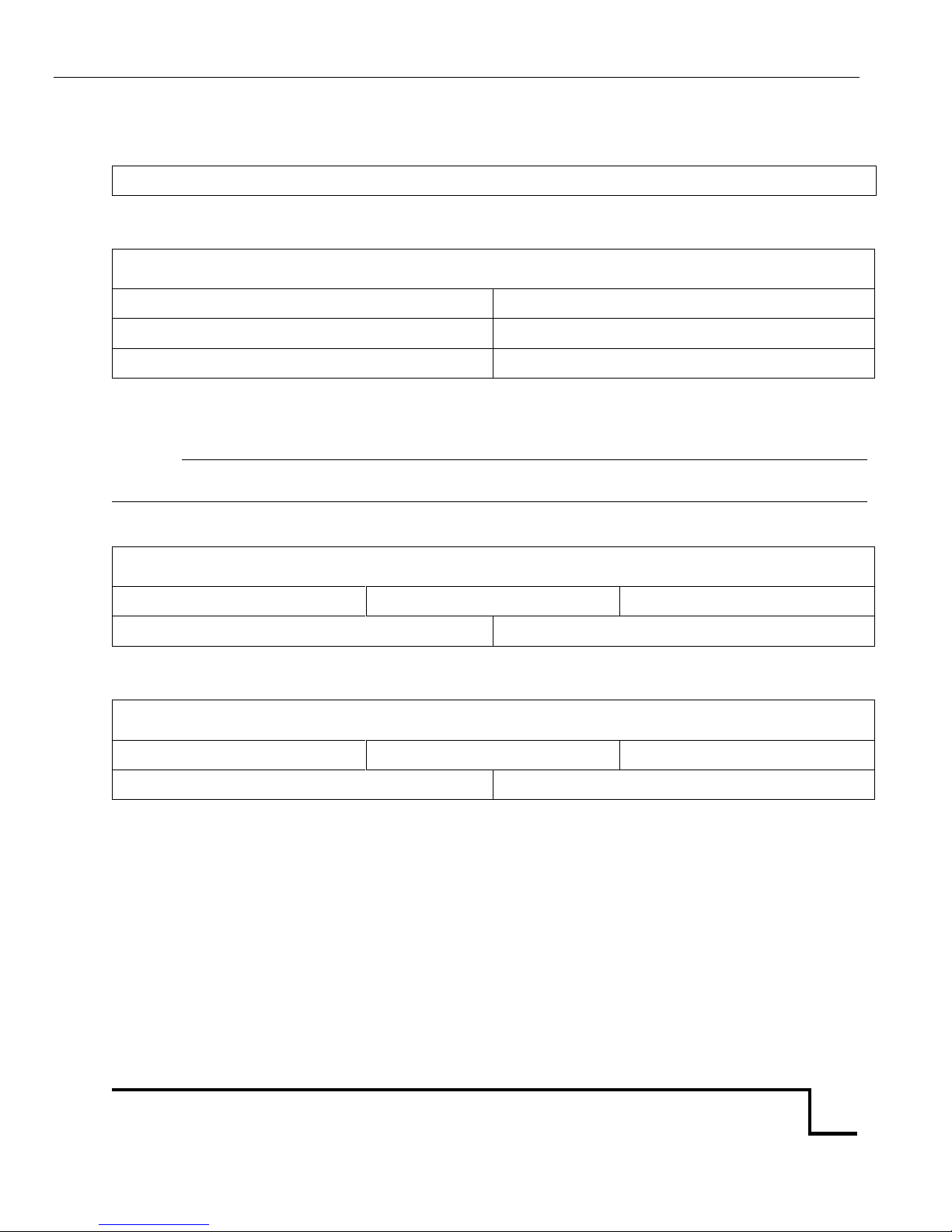
CI-203 Instruction Manual rev. 8/9/2016
1554 NE 3rd Ave, Camas, WA 98607, USA
Phone (360) 833-8835 Fax (360) 833-1914 [email protected] http://www.cid-inc.com
37
CI-203 PRODUCTION TEST CHECK SHEET
SERIAL NUMBER:
TESTING FUNCTION
THRESHOLD: H L
THRESHOLD SET:
PRECHARGE:
SCAN WIDTH:
SCAN TIME:
STEP LENGTH:
NOTES:
CONVEYOR AND/OR ROOT LENGTH
THRESHOLD SET:
SCAN WIDTH:
SCAN TIME:
PRECHARGE:
STEP LENGTH:
ROOT LENGTH
THRESHOLD SET:
SCAN WIDTH:
SCAN TIME:
PRECHARGE:
STEP LENGTH:
Page 40

CI-203 Instruction Manual rev. 8/9/2016
1554 NE 3rd Ave, Camas, WA 98607, USA
Phone (360) 833-8835 Fax (360) 833-1914 [email protected] http://www.cid-inc.com
38
WARRANTY REGISTRATION CARD
1554 NE 3rd Ave, Camas, WA 98607, USA
Phone: (360) 833-8835 Fax: (360) 833-1914 e-mail: [email protected] Web: www.cid-inc.com
PRODUCT REGISTRATION CARD
Please complete and return this form to CID within 30 days to
validate your Warranty on Parts and Labor.
Registration Information:
Your Name:____________________________________ Title:__________________
Company/University:___________________________________________________
Address:_____________________________________________________________
City:____________________________ State:__________ Zip:__________________
Country:__________________________Email_______________________________
Phone:______________________________ Fax:____________________________
CID Serial Number(s):__________________________________________________
Purchase Date:_____________________ Purchase Price:_____________________
------------------------------------------------------------------------------------------------------------------
FOLD ON DOTTED LINE
Your opinions will help improve our service. Please answer the following questions.
1. What was the basis of your product selection?
□ Representative Recommendation □ Price
□ Product Features □ Product Design
□ Technical Specifications □ Brand Name
□ Warranty □ Service
□ Other _________________________________________
2. What other competing brands did you consider? __________________________
3. Where did you first learn of this product?
□ Advertisement in ________________________________ □ Representative
□ Friend/Colleague □ Exhibit
□ Other _________________________________________
4. Who selected this product?
□ I did □ Research Group
□ University Department □ Purchasing
□ Other _________________________________________
5. Comments/Suggestions:
______________________________________________________________________
______________________________________________________________________
___________________________________________________
 Loading...