

Page 1
WW1020/WW1000
Operation Manual
- English
Catalog Number WW1922en
Version 0, April 2009
2009 Smiths Medical family of companies. All rights reserved.
©
Page 2

Page 3

Table of Contents
Table of Contents
Warranty and Service Information ......................................................................v
Proprietary Notice ...................................................................................................................................................... v
Warranty ........................................................................................................................................................................v
Limited Warranty ................................................................................................................................................ v
Disclaimer of Warranties .................................................................................................................................. v
Conditions of Warranty .................................................................................................................................... v
Limitation of Remedies .................................................................................................................................... v
Warranty Procedure .................................................................................................................................................. vi
CE Notice ......................................................................................................................................................................vi
Chapter 1: Introduction ................................................................................... 1-1
About the Manual ..................................................................................................................................................1-1
Denition of Symbols ...........................................................................................................................................1-1
Warnings ....................................................................................................................................................................1-3
Cautions ..................................................................................................................................................................... 1-7
Notes ........................................................................................................................................................................... 1-8
Chapter 2: Intended Use and Monitor Features ............................................. 2-1
Intended Use for the WW1020 Oximeter .......................................................................................................2-1
Intended Use for the WW1000 Oximeter .......................................................................................................2-1
Monitor Features ....................................................................................................................................................2-1
Theory of Operation .............................................................................................................................................. 2-2
Pulse Amplitude Index .........................................................................................................................................2-3
Patented Technology (WW1020 only) ............................................................................................................ 2-3
Chapter 3: Controls and Features .................................................................... 3-1
Front Display ............................................................................................................................................................3-1
Monitor Operating Key ......................................................................................................................................... 3-2
Monitor Back and Bottom Panels ..................................................................................................................... 3-3
Chapter 4: Operating Instructions .................................................................. 4-1
Unpacking the Monitor ........................................................................................................................................ 4-1
Powering the Oximeter ........................................................................................................................................ 4-1
Installing the Batteries .......................................................................................................................................... 4-3
External Power ........................................................................................................................................................4-4
AC Power ................................................................................................................................................................... 4-5
USB Power (Universal Serial Bus) ...................................................................................................................... 4-6
Turning On the Monitor ....................................................................................................................................... 4-7
Checking the Monitor’s Conguration ........................................................................................................... 4-8
Checking the Monitor’s Performance ............................................................................................................. 4-8
Attaching the Sensor to the Patient ................................................................................................................ 4-9
Choosing the Sensor ...........................................................................................................................................4-10
BCI® Sensors ...................................................................................................................................................4-10
Clinician’s Operation Manual i
Page 4

Table of Contents
Nellcor® Sensor (WW1020 Only) ............................................................................................................4-11
Cleaning or Disinfecting the Sensors ............................................................................................................4-11
Checking the Sensor and Oximetry Cable...................................................................................................4-11
Pulse Amplitude Index .......................................................................................................................................4-12
Storing the Sensor ................................................................................................................................................4-14
Home Use ................................................................................................................................................................4-15
Equipment and Supplies Checklist for Home Use ...........................................................................4-15
Training the Home Use Caregiver ..........................................................................................................4-16
Chapter 5: Patient Record Number and Trend Data.......................................5-1
Description ............................................................................................................................................................... 5-1
Incrementing the Patient Record Number ...................................................................................................5-1
Memory Capacity ................................................................................................................................................... 5-1
Clearing Trend Data ............................................................................................................................................... 5-1
Trend Data Output ................................................................................................................................................. 5-1
Chapter 6: Optional Docking Station and Printer .......................................... 6-1
Description ............................................................................................................................................................... 6-1
Docking Station ...................................................................................................................................................... 6-2
Powering the Docking Station .................................................................................................................. 6-2
WW1090 Lithium-Ion (Li+) Rechargeable Battery Pack ...................................................................6-3
Installing the Oximeter to the Dock ........................................................................................................ 6-3
Downloading Data to PC ............................................................................................................................6-3
Printer ......................................................................................................................................................................... 6-4
Attaching the Printer .................................................................................................................................... 6-5
Loading Paper ................................................................................................................................................. 6-6
Choosing the Print Mode ........................................................................................................................... 6-7
Trend Data Condition Flags ................................................................................................................................6-8
Chapter 7: PC Communication Setup ..............................................................7-1
Description ............................................................................................................................................................... 7-1
Power Input and Data Connector Port .........................................................................................................7-2
How to Set Up Equipment .......................................................................................................................... 7-3
Sensor / RS232 Port ................................................................................................................................................7-4
How to Set Up Equipment .......................................................................................................................... 7-4
Output Format ................................................................................................................................................ 7-5
Chapter 8: Maintenance ................................................................................... 8-1
Routine Maintenance ............................................................................................................................................ 8-1
Cleaning and Disinfecting ................................................................................................................................... 8-2
Storage .......................................................................................................................................................................8-2
Chapter 9: Troubleshooting ............................................................................. 9-1
Power .......................................................................................................................................................................... 9-1
Sensor .........................................................................................................................................................................9-2
Other ........................................................................................................................................................................... 9-3
ii Clinician’s Operation Manual
Page 5

Table of Contents
Chapter 10: Optional Supplies and Accessories ........................................... 10-1
Ordering Information ..........................................................................................................................................10-2
Chapter 11: Specications .............................................................................11-1
Displays ....................................................................................................................................................................11-1
Indicators .................................................................................................................................................................11-1
Keys/User Controls ...............................................................................................................................................11-1
SpO2 for the WW1020 Oximeter ......................................................................................................................11-2
Pulse Rate for the WW1020 Oximeter ...........................................................................................................11-3
SpO2 for the WW1000 Oximeter ......................................................................................................................11-4
Pulse Rate for the WW1000 Oximeter ...........................................................................................................11-5
Pulse Amplitude Index for the WW1020 Oximeter ..................................................................................11-6
Pulse Amplitude Index for the WW1000 Oximeter ..................................................................................11-6
Printer .......................................................................................................................................................................11-6
Serial Data Output ................................................................................................................................................11-7
Power Input and Data Connector .........................................................................................................11-7
Sensor Connector ........................................................................................................................................11-7
Power Requirements ...........................................................................................................................................11-7
Battery ..............................................................................................................................................................11-7
AC Charger .....................................................................................................................................................11-7
USB ....................................................................................................................................................................11-7
Monitor Dimensions ............................................................................................................................................11-7
Dock Dimensions ..................................................................................................................................................11-8
Auxiliary Inputs/Outputs ...................................................................................................................................11-8
Environmental .......................................................................................................................................................11-8
Equipment Classication ...................................................................................................................................11-9
Design Standards .................................................................................................................................................11-9
Appendix A: Guidance and Manufacturer’s Declaration ...............................A-1
Guidance and Manufacturer’s Declaration ...................................................................................................A-1
Electromagnetic Emissions - Emissions Test ........................................................................................A-1
Electromagnetic Immunity - Immunity Test .................................................................................................A-2
Recommended Separation Distances .............................................................................................................A-4
The serial autocorrelation technology (SAC) in the WW1020 oximeter is covered by U.S. Patent No.
5,558,096.
BCI, Comfort Clip and the Smiths design mark are trademarks of the Smiths Medical family of
companies. The symbol ® indicates the trademark is registered in the U.S. Patent and Trademark
Oce and certain other countries. All other names and marks mentioned are the trade names,
trademarks or service marks of their respective owners.
Clinician’s Operation Manual iii
Page 6

Table of Contents
This page is intentionally left blank.
iv Clinician’s Operation Manual
Page 7

Warranty and Service Information
Warranty and Service Information
Proprietary Notice
Information contained in this document is copyrighted by Smiths Medical PM, Inc. and may not be
duplicated in full or part by any person without prior written approval of Smiths Medical PM, Inc.
Its purpose is to provide the user with adequately detailed documentation to eciently install,
operate, maintain, and order spare parts for the device supplied. All information contained in this
document is believed to be current and accurate as of the date of publication or revision, but does
not constitute a warranty.
Warranty
Limited Warranty
Smiths Medical PM, Inc. (“Seller”) warrants to the original purchaser that the Product, not
including accessories, shall be free from defects in material and workmanship under normal use,
if used in accordance with its labeling, for three years from the date of shipment to the original
purchaser.
Seller warrants to the original purchaser that the reusable oximeter sensors supplied as
accessories, shall be free from defects in materials and workmanship under normal use, if used
in accordance with its labeling, for one year from the date of shipment to the original purchaser
(USA only).
Disclaimer of Warranties
THE FOREGOING EXPRESS WARRANTY, AS CONDITIONED AND LIMITED, IS IN LIEU OF AND
EXCLUDES ALL OTHER WARRANTIES WHETHER EXPRESS OR IMPLIED, BY OPERATION OF
LAW OR OTHERWISE, INCLUDING BUT NOT LIMITED TO, ANY IMPLIED WARRANTIES OF
MERCHANTABILITY OR FITNESS FOR A PARTICULAR PURPOSE.
Seller disclaims responsibility of the suitability of the Product for any particular medical treatment
or for any medical complications resulting from the use of the Product. This disclaimer is dictated
by the many elements which are beyond Seller’s control, such as diagnosis of patient, conditions
under which the Product may be used, handling of the Product after it leaves Seller’s possession,
execution of recommended instructions for use and others.
Conditions of Warranty
This warranty is void if the Product has been altered, misused, damaged by neglect or accident,
not properly maintained or recharged, or repaired by persons not authorized by Seller. Misuse
includes, but is not limited to, use not in compliance with the labeling or use with accessories not
manufactured by Seller. This warranty does not cover normal wear and tear and maintenance
items.
Limitation of Remedies
The original purchaser’s exclusive remedy shall be, at Seller’s sole option, the repair or
replacement of the Product. THIS IS THE EXCLUSIVE REMEDY. In no event will Seller’s liability
arising out of any cause whatsoever (whether such cause is based on contract, negligence,
strict liability, tort or otherwise) exceed the price of the Product and in no event shall Seller
be responsible for consequential, incidental, or special damages of any kind or nature
whatsoever, including but not limited to, lost business, revenues, and prots.
Clinician’s Operation Manual v
Page 8

Warranty and Service Information
Warranty Procedure
To obtain warranty service in the USA, you must request a Return Authorization (RA) number from
Technical Service. Reference the RA number when returning your Product, freight and insurance
prepaid, to:
Smiths Medical PM, Inc.
N7W22025 Johnson Drive
Waukesha, WI 53186-1856
Seller will not be responsible for unauthorized returns or for loss or damage to the Product
during the return shipment. The repaired or replaced Product will be shipped, freight prepaid, to
Purchaser.
To obtain warranty information outside of the USA, contact your local distributor.
Keep all original packing material, including any inserts. If you need to ship the device, use only
the original packaging material, including inserts. Box and inserts should be in original condition.
If original shipping material in good condition is not available, it should be purchased from Smiths
Medical PM, Inc.
Damages occurring in transit in other than original shipping containers are the responsibility of
the shipper. All costs incurred returning devices for repair are the responsibility of the shipper.
Phone: (262) 542-3100
Fax: (262) 542-0718
Toll Free: (800) 558-2345
CE Notice
Marking by the symbol 2 indicates compliance of this device to the Medical Device Directive
93/42/EEC.
@
Australian Representative:
Authorized Representative (as dened by the Medical Device Directive):
Smiths Medical International Ltd.
Colonial Way, Watford, Hertfordshire,
WD24 4LG, UK
Smiths Medical Australasia Pty. Ltd.
61 Brandl Street, Eight Mile Plains,
QLD 4113, Australia
Phone: (44) 1923 246434
Fax: (44) 1923 240273
Tel: +61 (0) 7 3340 1300
vi Clinician’s Operation Manual
Page 9
Chapter 1: Introduction
Chapter 1: Introduction
About the Manual
The Clinician’s Operation Manual provides installation, operation, and maintenance instructions
for the health-care professional trained in monitoring respiratory and cardiovascular activity.
These instructions contain important information for safe use of the product. Read the
entire contents of these Instructions For Use, including Warnings and Cautions, before using
the monitor. Failure to properly follow warnings, cautions and instructions could result in
death or serious injury to the patient.
Denition of Symbols
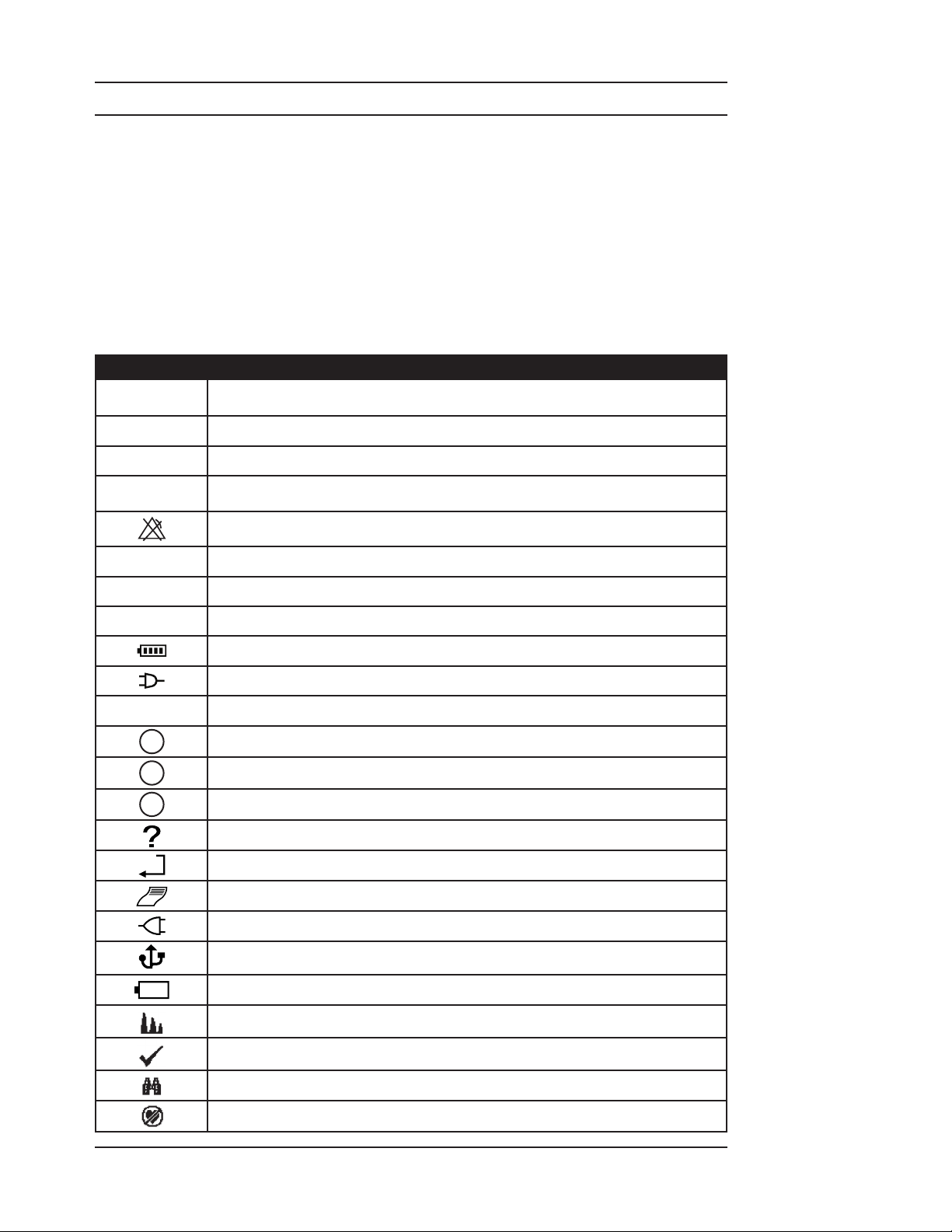
SYMBOL DEFINITION
6
R
Caution: Federal (U.S.A.) law restricts this device to sale by or on the order of a
physician.
Type BF Equipment
f
7
%SpO
p
PI
x
1
2
3
Attention, see instructions for use.
Refer servicing to qualied service personnel.
This device has no alarms.
Percent Oxygen Saturation
2
Pulse Rate (beats per minute)
Pulse Amplitude Index
Battery Charge Indicator
External Power Indicator
On/O Key
Printer LED - Real Time Printout
Printer LED - Numeric Trend Tables
Printer LED - Graphic Trend
Printer LED - Error
Printer Key - Select Print
Printer Key - Start / Stop Print
Docking Station LED - AC Power
Docking Station LED - USB Power
Docking Station LED - Charging Spare Battery
Printer icon: Small Pulse (WW1020 only)
Printer icon: Check Sensor
Printer icon: Searching too Long
Printer icon: Lost Pulse
Clinician’s Operation Manual 1-1
Page 10

Chapter 1: Introduction
SYMBOL DEFINITION
Printer icon: Artifact (WW1020 only)
7
K
1
D
E
G
IPX2
<
J
@
Z
Collect
Separately
Y
Do not reuse. One use on one patient.
Moisture Sensitive
Not suitable for use in the presence of a ammable anesthetic mixture.
Output Voltage Connector
Input Voltage Connector
Direct Current
Drip proof (monitor and dock only)
Catalog Number
Date of Manufacture
Authorized Representative in the European Community
Disposal (EU Countries)
Under the Waste Electrical and Electronic Equipment (WEEE) Directive
2006/96/EC and implementing regulations, all devices and service items
within the scope of the Directive purchased new after August 13, 2005 must
be sent for recycling when ultimately becoming waste. Devices and items
must not be disposed of with general waste.
If purchased before that date, they may also be sent for recycling if being
replaced on a one-for-one, like-for-like basis (this varies depending on the
country). Recycling instructions to customers using Smiths Medical products
are published on the internet at:
http://www.smiths-medical.com/recycle
Disposal (other countries)
When disposing of this device, its batteries or any of its accessories, ensure
that any negative impact on the environment is minimized. Contact your
local waste disposal service and use local recycling or disposal schemes.
Separate any other parts of the equipment where arrangements can be made
for their recovery; either by recycling or energy recovery. The main batteries
are potentially harmful and will require separate disposal according to
manufacturer’s instructions or local regulations.
Note: If applicable, EU, national or local regulations concerning waste
disposal must take precedence over the above advice.
1-2 Clinician’s Operation Manual
Page 11

Chapter 1: Introduction
KEYWORD
WARNING
CAUTION
NOTE
Something that could hurt the patient or hurt the operator.
Something that could damage the monitor.
Other important information.
DEFINITION
Warnings
WARNING! This device is not intended for continuous patient monitoring. This device is
intended to measure the patient’s %SpO2 and pulse rate values. There are no
audible or visible alarms.
WARNING! The monitor was not designed or tested to be an apnea monitor.
WARNING! Do not use this device in the presence of ammable anesthetics.
WARNING! Do not use this device in the presence of magnetic resonance imaging (MR or
MRI) equipment.
WARNING! Operation of this device may be adversely aected in the presence of
conducted transients or strong electromagnetic (EM) or radiofrequency
(RF) sources, such as portable and mobile RF communication equipment,
electrosurgery and electrocautery equipment, x-rays, and high intensity
infrared radiation.
WARNING! Operation of this device may be adversely aected in the presence of computed
tomograph (CT) equipment.
WARNING! Any monitor that has been dropped or damaged should be inspected by
qualied service personnel, prior to use, to insure proper operation.
WARNING! If the accuracy of any measurement is in question, verify the patient’s vital signs
by an alternative method,and then check the monitor for proper functioning.
WARNING! This device must be used in conjunction with clinical signs and symptoms. This
device is only intended to be an adjunct in patient assessment.
WARNING! This device is intended for use by persons trained in professional health care or
those who have access to the oversight of a professional health care provider.
The operator must be thoroughly familiar with the information in this manual
before using the device.
WARNING! Prolonged use or the patient’s condition may require changing the sensor site
periodically. Change sensor site and check skin integrity, circulatory status, and
correct alignment at least every 4 hours.
WARNING! When attaching sensors with Microfoam® tape, do not stretch the tape or
attach the tape too tightly. Tape applied too tightly may cause inaccurate
readings and blisters on the patient’s skin (lack of skin respiration, not heat,
causes the blisters).
WARNING! Use only SpO2 sensors supplied with, or specically intended for use with, this
device.
Clinician’s Operation Manual 1-3
Page 12

Chapter 1: Introduction
WARNING! Incorrectly applied sensors may give inaccurate readings. 2 Refer to the
sensor insert for proper application instructions.
WARNING! Do not autoclave, ethylene oxide sterilize, or immerse the sensors in liquid. This
may cause damage to the sensor which may cause inaccurate readings.
WARNING! Unplug the sensor from the oximeter before cleaning or disinfecting to prevent
damaging the sensor or monitor, and to prevent user safety hazards.
WARNING! Measurements made at sites with low perfusion are potentially inaccurate.
Always use measurements in conjunction with other clinical signs and
symptoms.
WARNING! SpO2 measurements may be adversely aected in the presence of high ambient
light. Shield the sensor area (with a surgical towel, for example) if necessary.
WARNING! Dyes introduced into the bloodstream, such as methylene blue, indocyanine
green, indigo carmine, uorescein, and patent blue V (PBV) may adversely
aect the accuracy of the SpO2 reading.
WARNING! Any condition that restricts blood ow, such as use of a blood pressure cu or
extremes in systemic vascular resistance, may cause an inability to determine
accurate pulse rate and SpO2 readings.
WARNING! Optical cross-talk can occur when two or more sensors are placed in close
proximity. It can be eliminated by covering each site with an opaque material.
WARNING! Remove ngernail polish or false ngernails before applying SpO2 sensors.
Fingernail polish or false ngernails may cause inaccurate SpO2 readings.
WARNING! Signicant levels of dysfunctional hemoglobins, such as carboxyhemoglobin
(with CO-poisoning) or methemoglobin (with sulfonamide therapy), will aect
the accuracy of the SpO2 measurement.
WARNING! Tissue damage may result from overexposure to sensor light during
photodynamic therapy with agents such as verteporphin, pormer sodium,
and metatetrahydroxyphenylchlorin (mTHPC). Change the sensor site at least
every hour and observe for signs of tissue damage. More frequent sensor site
changes/inspections may be indicated depending upon the photodynamic
agent used, agent dose, skin condition, total exposure time or other factors.
Use multiple sensor sites.
WARNING! When connecting this monitor to any instrument, verify proper operation
before clinical use. Refer to the instrument’s user manual for full instructions.
Accessory equipment connected to the monitor’s data interface must be
certied according to the respective IEC standards, i.e., IEC 60950 for data
processing equipment or IEC 60601-1 for electromedical equipment. All
combinations of equipment must be in compliance with IEC 60601-1-1 systems
requirements. Anyone connecting additional equipment to the signal input
port or the signal output port congures a medical system, and therefore is
responsible that the system complies with the requirements of the system
standard IEC 60601-1-1.
1-4 Clinician’s Operation Manual
Page 13

Chapter 1: Introduction
R 1.5 m (4.9 ft.)
WARNING! IEC 60950 approved equipment must be placed outside the “patient
environment.” The patient environment is dened as an area 1.5 m (4.92 feet)
from the patient.
Figure 1-1: Patient Environment
WARNING! The oximeter will not operate without batteries installed. Properly charged
batteries provide a reserve source of power in case of external power failure.
Never use an oximeter with discharged batteries to monitor a patient.
WARNING! Inspect battery terminals for corrosion or contamination. The monitor may not
operate properly if battery terminals are corroded or contaminated. Do not use
until battery terminals have been properly cleaned and repaired.
WARNING! Check expiration date of batteries. The monitor may not operate properly if
expired batteries are used. Do not use until proper batteries can be obtained.
WARNING! Remove device batteries prior to long term storage.
WARNING! Do not allow the patient to handle the device if the battery door has been
removed, except while installing new batteries.
WARNING! Disconnect the external power supply from the monitor or Docking Station
before disinfecting or cleaning the monitor.
WARNING! Do not plug the monitor or Docking Station into an outlet controlled by a wall
switch.
WARNING! Disconnect the AC power supply from the outlet before disconnecting it from
the monitor. Leaving the AC power supply connected to an AC power outlet
without being connected to the monitor may result in a safety hazard.
WARNING! Do not allow any moisture to contact the AC power supply connectors, or
a safety hazard may result. Ensure that hands are thoroughly dry before
handling the AC power supply.
WARNING! Do not place the monitor or Docking Station in the patient’s bed or crib. Do not
place the monitor or Docking Station on the oor.
WARNING! Failure to place the monitor or Docking Station away from the patient may
allow the patient to turn o, reset, or damage the monitor, possibly resulting
in the patient not being monitored. Make sure the patient cannot reach the
monitor from their bed or crib.
Clinician’s Operation Manual 1-5
Page 14

Chapter 1: Introduction
WARNING! Failure to carefully route the cable from the sensor to the monitor may allow
the patient to become entangled in the cable, possibly resulting in patient
strangulation. Route the cable in a way that will prevent the patient from
becoming entangled in the cable. If necessary, use tape to secure the cable.
WARNING! If there is a risk of the AC power supply becoming disconnected from the
monitor during use, secure the cord to the monitor several inches from the
connection.
WARNING! Ensure the device’s AC rating is correct for the AC voltage at your installation
site before using this monitor. The monitor’s AC rating is shown on the external
power supply. If the rating is not correct, do not use the monitor. Contact
the Smiths Medical PM, Inc. service department, or your authorized service
representative, for help.
WARNING! Use only the power supply included with your monitor, or approved by Smiths
Medical PM, Inc. Use of an inappropriate power supply may cause a patient
shock hazard or cause the oximeter to stop monitoring. See Chapter 10:
Optional Supplies & Accessories, for additional specic information.
WARNING! The Docking Station must have a Printer or Printer Port Cover installed. Failure
to do so may cause a risk of electrical shock to the patient or operator or risk
damage to the equipment.
WARNING! Under certain clinical conditions, pulse oximeters may display dashes if
unable to display SpO2 and/or pulse rate values. Under these conditions, pulse
oximeters may also display erroneous values. These conditions include, but are
not limited to: patient motion, low perfusion, cardiac arrhythmias, high or low
pulse rates or a combination of the above conditions. Failure of the clinician to
recognize the eects of these conditions on pulse oximeter readings may result
in patient injury.
WARNING! Verify that all LEDs (light emitting diodes) on the display light up upon startup
of the device.
1-6 Clinician’s Operation Manual
Page 15

Chapter 1: Introduction
Cautions
CAUTION! Federal (U.S.A.) law restricts this device to sale by or on the order of a physician.
CAUTION! 7 Do not disassemble unit, not user serviceable. Refer to qualied service
personnel.
CAUTION! Failure to charge the monitor while the monitor is in long term storage may
shorten the battery life. Charge the monitor while it is in storage to ensure the
longest battery life.
CAUTION! Due to limitations of the Li-Ion chemistry, the rechargeable battery pack
should not be charged at ambient temperatures above 45 °C (113 °F) or
below 5 °C (41 °F).
CAUTION! The WW1090 rechargeable battery pack is shipped with only 30% of full charge.
The battery pack must be charged completely before use.
CAUTION! The WW1090 rechargeable battery pack utilizes Li-Ion secondary cells. Dispose
of spent batteries in compliance with your institution’s guidelines and local
ordinances.
CAUTION! Observe proper battery polarity (direction) when replacing batteries.
CAUTION! Do not allow water or any other liquid to spill onto the monitor or Docking
Station. Do not autoclave, ethylene oxide sterilize, or immerse the monitor or
Docking Station in liquid. Evidence that liquid has been allowed to enter the
monitor or Docking Station voids the warranty.
CAUTION! Where the equipment has accidentally gotten wet, it should be wiped dry
externally and allowed to dry thoroughly before use.
CAUTION! Before cleaning or disinfecting the printer, unplug the AC adapter, remove the
batteries and remove the paper.
CAUTION! Do not allow printer paper to become wet. If the printer paper gets wet, remove
the paper immediately. Do not use the printer until the paper is replaced.
CAUTION! Chemicals used in some cleaning agents may cause brittleness of plastic parts.
Follow cleaning instructions in this manual.
CAUTION! Cleaning with disinfectants, including alcohol, may shorten the life of the plastic
or electronic parts, but appropriate disinfection must still be performed.
CAUTION! Pressing any key with sharp or pointed instruments may permanently damage
the keypad. Only press keys with your nger.
Clinician’s Operation Manual 1-7
Page 16

Chapter 1: Introduction
Notes
NOTE: The WW1090 rechargeable battery pack utilizes circuitry that optimizes the
charging of the batteries. New packs will require multiple charge / discharge
learning cycles before optimum performance is obtained.
NOTE: “SpO2 averaging” means the number of pulse beats over which the SpO2 value is
averaged; “pulse averaging” means the number of seconds over which the pulse
value is averaged.
NOTE: Increasing or decreasing the averaging setting has no eect on the data update
rate.
NOTE: A Patient Simulator does not calibrate the monitor. The monitor does not require
calibration. A Patient Simulator provides a known SpO2 and pulse rate to the
monitor that allows the monitor’s performance to be checked.
NOTE: A Patient Simulator cannot be used to assess the accuracy of a pulse oximeter and/
or sensor.
1-8 Clinician’s Operation Manual
Page 17

Chapter 2: Intended Use and Monitor Features
Chapter 2: Intended Use and Monitor Features
Intended Use for the WW1020 Oximeter
The BCI® WW1020 pulse oximeter is intended for spot-checking applications (non continuous
use). It monitors and displays patient’s functional oxygen saturation (%SpO2), pulse rate
(
), pulse signal strength, and pulse amplitude index (PI) readings. It may be used by
p
physicians, respiratory therapists, nurses, certied nurse assistants, emergency medical
technicians, sleep technicians, and home users. The intended patient population ranges from
neonatal to adult. It may be used on patients with low perfusion or during patient motion. The
WW1020 may be used in the hospital or clinical environment, during emergency land transport,
and in the home.
WARNING! The monitor was not designed or tested to be an apnea monitor.
Intended Use for the WW1000 Oximeter
The BCI® WW1000 pulse oximeter is intended to be used for spot-checking (non-continuous use).
It monitors and displays a patient’s functional oxygen saturation (%SpO2), pulse rate (
signal strength, and pulse amplitude index (PI) readings. It may be used by physicians, respiratory
therapists, nurses, certied nurse assistants, emergency medical technicians, sleep technicians,
clinicians, and home users. The intended patient population ranges from infant to adult. It can
be used on patients with low perfusion. The WW1000 may be used in the hospital or clinical
environment, during emergency land transport, and in the home.
p
), pulse
WARNING! The monitor was not designed or tested to be an apnea monitor.
Monitor Features
Provides fast, reliable SpO•
any patient, from neonate to adult for the WW1020 or from small infant to adult for the
WW1000.
Maintains accurate readings during periods of patient motion (WW1020 only) and when •
monitoring patients with low perfusion.
Ideally suited for use in hospitals, outpatient clinics, emergency rooms, during emergency •
land transport, in sleep labs, or in-home use.
Portable and lightweight. Weighs only 330 grams (12 ounces), with 4 “AA” batteries.•
On-board sensor storage cradle holds the nger sensor when not in use.•
Power options include four (4) standard “AA” (type IEC LR6) alkaline batteries, a •
rechargeable Lithium Ion battery pack, USB power, or an AC power adapter.
Rechargeable battery life for a new battery is approximately thirty-one • (31) hours for the
WW1020, fty-four (54) hours for the WW1000.
An easy to read battery gauge indicates the charge level and provides a low battery alert.•
Large, bright, easy-to-read LED display indicates SpO•
2 Nine-segment LED bar graphs indicate pulse signal strength and pulse amplitude index.•
, pulse rate, and pulse signal strength measurements on
2
and pulse rate measurements.
2
Optional docking station transforms the device into a table top pulse oximeter, and can •
also be used to recharge the monitor’s lithium Ion battery pack, and a spare battery pack.
Optional printer allows for printing of trend information or real time data logs.•
Clinician’s Operation Manual 2-1
Page 18
Chapter 2: Intended Use and Monitor Features
Theory of Operation
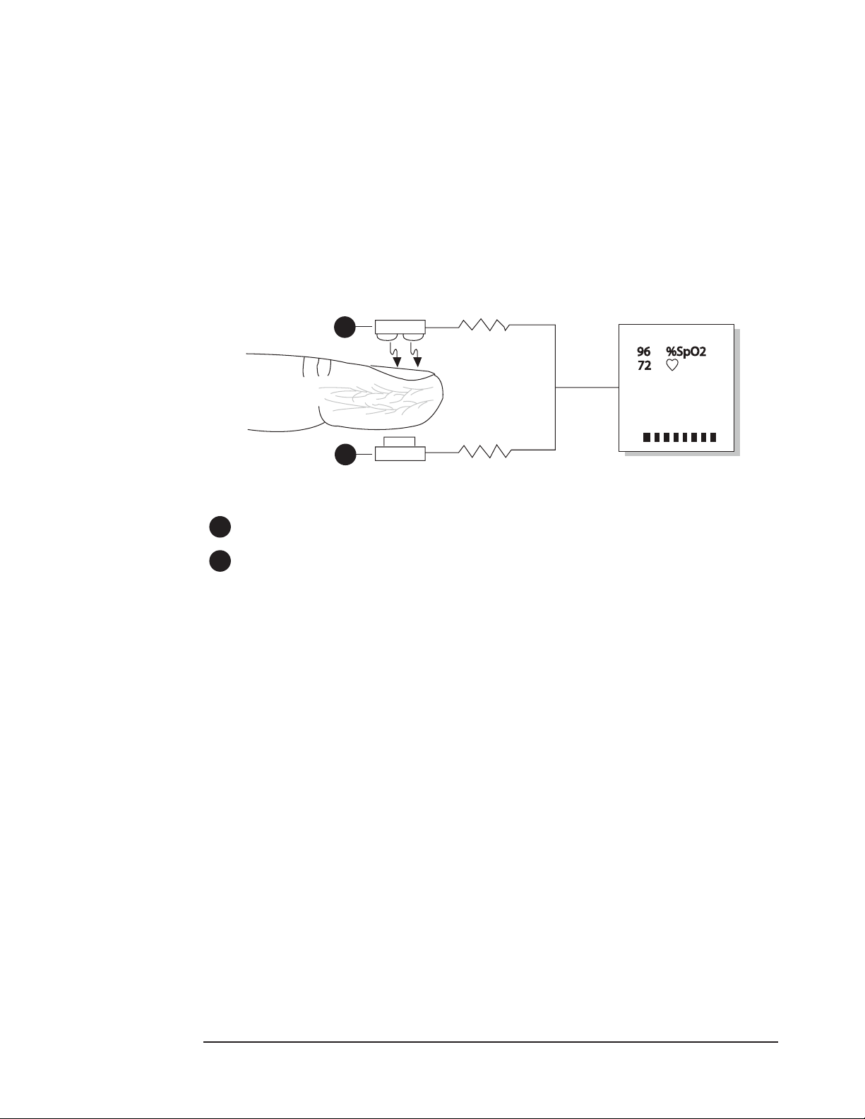
The pulse oximeter determines %SpO2 and pulse rate by passing two wavelengths of low
intensity light, one red and one infrared, through body tissue to a photodetector. Information
about wavelength range can be especially useful to clinicians. Wavelength information for this
device can be found in the SpO2 Specications section of this manual.
Pulse identication is accomplished by using plethysmographic techniques, and oxygen
saturation measurements are determined using spectrophotometric oximetry principles. During
measurement, the signal strength resulting from each light source depends on the color and
thickness of the body tissue, the sensor placement, the intensity of the light sources, and the
absorption of the arterial and venous blood (including the time varying eects of the pulse) in the
body tissues.
1
2
Figure 2-1: Theory of Operation
1
Low intensity Red and Infrared LED light sources
2
Detector
The oximeter processes these signals, separating the time invariant parameters (tissue thickness,
skin color, light intensity, and venous blood) from the time variant parameters (arterial volume
and SpO2) to identify the pulses and calculate functional oxygen saturation. Oxygen saturation
calculations can be performed because blood saturated with oxygen predictably absorbs less red
light than oxygen-depleted blood.
WARNING! Since measurement of SpO2 depends on a pulsating vascular bed, any
condition that restricts blood ow, such as the use of a blood pressure cu or
extremes in systemic vascular resistance, may cause an inability to determine
accurate SpO2 and pulse rate readings.
WARNING! Under certain clinical conditions, pulse oximeters may display dashes if
unable to display SpO2 and/or pulse rate values. Under these conditions, pulse
oximeters may also display erroneous values. These conditions include, but are
not limited to: patient motion, low perfusion, cardiac arrhythmias, high or low
pulse rates or a combination of the above conditions. Failure of the clinician to
recognize the eects of these conditions on pulse oximeter readings may result
in patient injury.
2-2 Clinician’s Operation Manual
Page 19

Chapter 2: Intended Use and Monitor Features
Pulse Amplitude Index
The PI value is a relative measure of pulse-signal strength over time at a pulse oximeter
monitoring site, and is non-pulsatile in nature. Pulse Amplitude Index is dened as
PI = (100 * AC)/DC where AC is the alternating current (pulsatile component of the signal)
and DC is direct current (non-pulsatile component of the signal). For more information, see
Pulse Amplitude Index in Chapter 4: Operating Instructions.
NOTE! The PI value is a relative value that varies from patient to patient.
Patented Technology (WW1020 only)
This oximeter incorporates patented technology and noise reducing hardware to enhance the
oximeter’s ability to detect pulse amplitude in patients with poor peripheral perfusion. Blood
Pulse Detection Method Using Serial Autocorrelation (SAC), patent number 5,558,096, analyzes
a digitized signal, in real time, and compares it with previous pulse data. If similar characteristics
to previous data are recognized, the device conrms a valid pulse. In essence, an individual’s
pulse data is retained and used as a template to accept or reject future pulse signals. Patented
technology, digital signal processing, and a greatly improved signal to noise ratio, provide for
improved performance.
Clinician’s Operation Manual 2-3
Page 20

Chapter 2: Intended Use and Monitor Features
This page is intentionally left blank.
2-4 Clinician’s Operation Manual
Page 21
Chapter 3: Controls and Features
Chapter 3: Controls and Features
Front Display
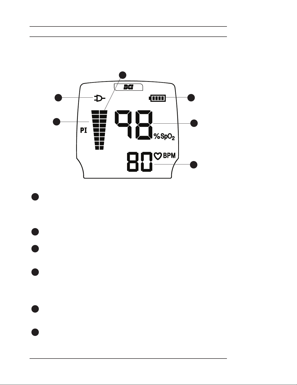
The display shows the measurements for SpO2 and Pulse Rate. It also shows a pulse strength
indicator, a pulse amplitude indicator and indicators for AC power and battery charge level.
3
2
1
Figure 3-1: Front Display
1
Pulse Amplitude Index Bar Graph - green / yellow
The pulse amplitude index bar graph is used to assist the operator in locating the oximetry
sensor site with the best pulse signal strength. A higher bar graph indicates a better quality
site. The bottom 2 bars turn yellow to indicate that the oximeter is receiving a low signal
quality from that sensor site.
2
External Power Indicator (X ) - green
This indicator is lit when the device is receiving power from the AC adapter or USB cable.
4
5
6
3
Pulse Signal Strength Bar Graph - red
The pulse strength bar graph “sweeps” with the patient’s pulse beat. The height of the bar
graph is a logarithmic representation of the pulse signal strength.
4
Battery Charge Indicator - green (yellow if low)
The battery charge indicator shows the current state of charge of the installed battery.
LED segments will disappear as the battery becomes weaker. When only one LED is lit and
ashing yellow, the batteries will expire within minutes; replace the batteries.
NOTE! This indicator is OFF if AA batteries are installed and X is illuminated.
5
SpO2 Numeric Display - red
A number shows the patient’s functional oxygen saturation value in percent. Dashes (--)
indicate the monitor is not able to calculate the SpO2 value.
6
Pulse Rate Numeric Display - red
A number shows the patient’s pulse rate value in beats per minute. Dashes (---) indicate the
monitor is not able to calculate the pulse rate value.
Clinician’s Operation Manual 3-1
Page 22
Chapter 3: Controls and Features
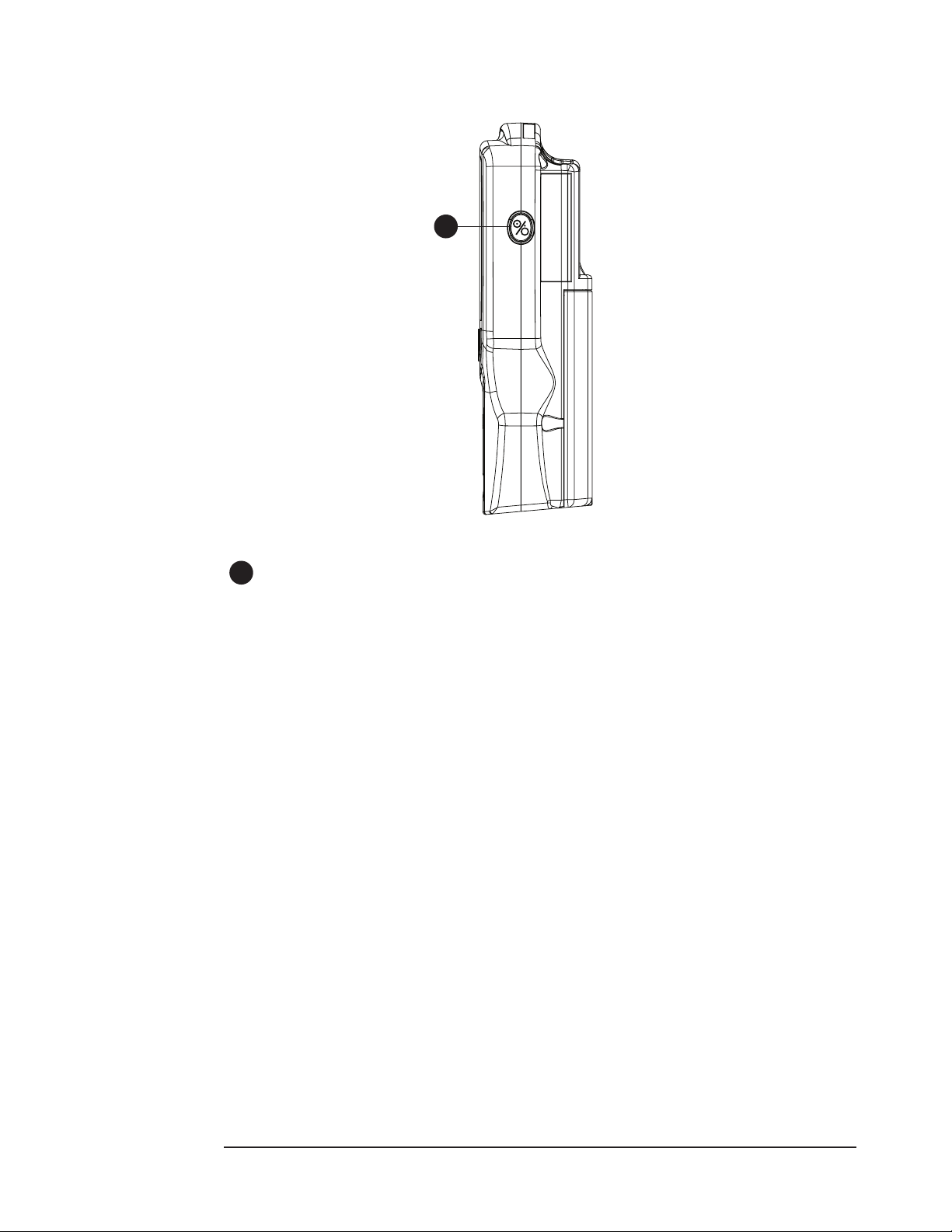
Monitor Operating Key
1
Figure 3-2: Monitor Operating Key
1
ON/OFF Key
x
Momentarily press this key when the device is OFF to turn the monitor ON. Press this key
when the device is ON to turn the monitor OFF.
Press and hold this key when the device is OFF to clear the patient trend data.
3-2 Clinician’s Operation Manual
Page 23
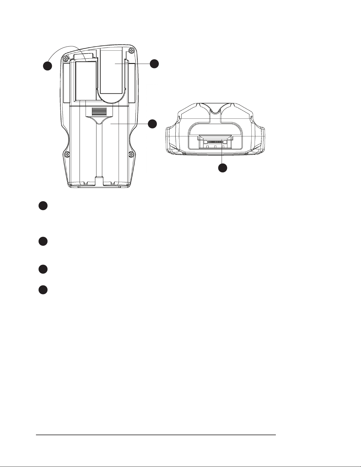
Monitor Back and Bottom Panels
Chapter 3: Controls and Features
1
Figure 3-3: Monitor Back and Bottom Panels
1
Sensor / RS232 Connector
The sensor or an extension cable attaches here. With the sensor removed, trend data can
be downloaded from this connector using an RS232 serial interface cable. See Chapter 7:
Connecting to a PC for details.
2
3
4
2
Sensor Storage Slot
Reusable BCI® sensors can be securely stored here when not in use by using a WW1080
Sensor Cradle.
3
Battery Compartment
This compartment holds the disposable batteries or the rechargeable battery pack.
4
Data Input/Output or Power Input Connector
This connector can accept the AC power adapter or the USB cable. The docking station uses
this connector for both power and data.
Clinician’s Operation Manual 3-3
Page 24

Chapter 3: Controls and Features
This page is intentionally left blank.
3-4 Clinician’s Operation Manual
Page 25

Chapter 4: Operating Instructions
Chapter 4: Operating Instructions
Unpacking the Monitor
The following items are shipped with the oximeter:
Monitor•
Three (3) sensor cradles (WW1080)•
Spot check sensor (3044S)•
Four (4) “AA” (LR6) alkaline batteries•
Operation manual•
Service manual (CD)•
Carefully remove the monitor and its accessories from the shipping carton. Save the packing
materials in case the monitor must be shipped or stored. Compare the packing list with the
supplies and equipment received.
Powering the Oximeter
The oximeter will operate from battery power or from external power with battery back up. The
optional WW1095 (30 Watt) AC power supply may be used to provide power to the oximeter. The
AC power supply is required when utilizing the docking station to ensure the proper operation
of the docking station with all accessories, including auxiliary battery charger and optional printer.
WARNING! The WW1020/WW1000 will not operate without batteries installed. Properly
charged batteries provide a reserve source of power in case of external power
failure. Never use an oximeter with discharged batteries to monitor a patient,
as the monitor may not operate properly in the case of external power failure.
The oximeter can obtain external power in the following ways:
The oximeter can be placed in its docking station. See • Chapter 6: Optional Docking Station
and Printer.
The AC power supply can be plugged directly into the oximeter (Figure 4-3).•
The AC power supply can be plugged into the WW1089 USB Interface Cable (Figure 4-4).•
The oximeter can be powered by a PC through the USB Interface cable (Figure 4-5).•
Clinician’s Operation Manual 4-1
Page 26
Chapter 4: Operating Instructions
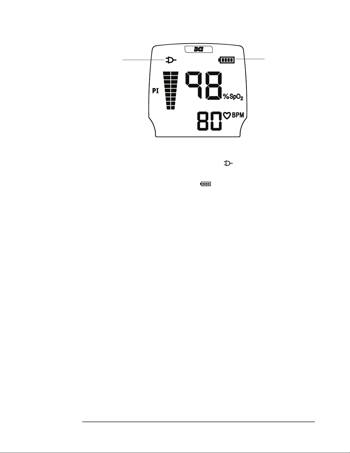
After connecting to power, verify that the green External Power Indicator is lit.
External Power
Indicator
Figure 4-1: External Power/Charge Indicators
Battery Charge
Indicator
If an AC source is present, the oximeter will draw power from it rst. While the oximeter is
operating from an AC source, the External Power Indicator ( ) will illuminate.
If there is enough power, the WW1090 Lithium-Ion (LI+) rechargeable battery pack will also
charge, if installed. The battery charge indicator ( ) will display segments showing the charge
level. As the battery charges, more green segments will light, until all four are lit.
NOTE: The AC Power supply does NOT charge “AA” (LR6) alkaline batteries.
If no external power source is available, the oximeter will draw battery power. When the battery
charge is low enough, the Battery Indicator shows one yellow segment. When the battery has less
than approximately 10 minutes of charge left, that segment will ash.
If no AC source is available, the oximeter will operate from an external USB source only when
attached to a WW1089 USB Interface Cable and energized USB connection. In this case, the
external power indicator lights. If enough power is available, the optional WW1090 Lithium-Ion
(Li+) rechargeable battery pack will trickle charge.
4-2 Clinician’s Operation Manual
Page 27
Chapter 4: Operating Instructions
+
+
+
+
Installing the Batteries
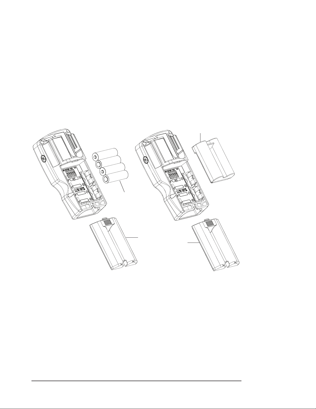
The oximeter uses four (4) standard “AA” alkaline, IEC Type LR6, cells (Figure 4-2A) or a custom
rechargeable Lithium-Ion (Li+) battery pack (WW1090 - Figure 4-2B).
WARNING! Inspect battery terminals for corrosion or contamination. The monitor may not
operate properly if battery terminals are corroded or contaminated. Do not use
until battery terminals have been properly cleaned and repaired.
WARNING! Check the expiration date for the batteries. The monitor may not operate
properly if expired batteries are used. Do not use until proper batteries can be
obtained.
WARNING! Remove the batteries prior to long term storage.
WARNING! Do not allow the patient to handle the device if the battery door has been
removed, except while installing new batteries.
Rechargeable Battery Pack
Batteries
Battery
Door
Figure 4-2A: AA (LR6) Alkaline Battery Placement Figure 4-2B: Rechargeable Lithium-Ion Battery Pack
To install/replace the batteries:
1.
2a. If using “AA” (LR6) alkaline batteries: Install the negative end of each battery rst,
NOTE: Dispose of spent batteries in compliance with your institution’s guidelines and local
2b. If using WW1090 Li-Ion (Li+) rechargeable battery pack: Align the battery pack so that
Depress the battery door tab near the center of the oximeter and slide the cover off toward
the bottom of the monitor.
compressing the battery terminal spring until the positive terminal clears the positive tab.
Press the battery down into place.
ordinances.
the metal connectors line up with the connectors in the WW1020/WW1000 battery
compartment. Push the WW1090 Lithium-Ion (Li+) rechargeable battery pack straight in to
place.
Battery
Door
Replace the battery door by sliding the cover back until the latch clicks.3.
Clinician’s Operation Manual 4-3
Page 28

Chapter 4: Operating Instructions
CAUTION! Due to limitations of the Li-Ion chemistry, the rechargeable battery pack
should not be charged at ambient temperatures above 45 °C (113 °F) or
below 5 °C (41 °F)
CAUTION! The WW1090 rechargeable battery pack is shipped with only 30% of full charge.
The battery pack must be charged completely before use.
CAUTION! The WW1090 rechargeable battery pack utilizes Li-Ion secondary cells. Dispose
of spent batteries in compliance with your institution’s guidelines and local
ordinances.
NOTE: The WW1090 rechargeable battery pack utilizes circuitry that optimizes the
charging of the batteries. New packs will require multiple charge / discharge
learning cycles before optimum performance is obtained.
NOTE: The rechargeable battery can be charged in the oximeter or in the spare bay of the
WW1025 Docking Station. The WW1095 AC power supply is required for charging,
and can be used with both the oximeter and the Docking Station.
External Power
WARNING! Disconnect the external power supply from the monitor before disinfecting or
cleaning the monitor.
WARNING! Do not plug the monitor into an outlet controlled by a wall switch.
WARNING! Do not allow any moisture to contact the AC power supply connectors, or a
safety hazard may result. Ensure that hands are thoroughly dry before handling
the AC power supply.
WARNING! Do not place the monitor in the patient’s bed or crib. Do not place the monitor
on the oor.
WARNING! Failure to place the monitor away from the patient may allow the patient to
turn o, reset, or damage the monitor, possibly resulting in the patient not
being monitored. Make sure the patient cannot reach the monitor from their
bed or crib.
WARNING! Failure to carefully route the cable from the sensor to the monitor may allow
the patient to become entangled in the cable, possibly resulting in patient
strangulation. Route the cable in a way that will prevent the patient from
becoming entangled in the cable. If necessary, use tape to secure the cable.
WARNING! If there is a risk of the AC power supply becoming disconnected from the
monitor during use, secure the cord to the monitor several inches from the
connection.
WARNING! Patient safety can be compromised by the use of a power supply not supplied
by Smiths Medical PM, Inc. Use only the power supply included with your
monitor, or one approved by Smiths Medical PM, Inc.
WARNING! Ensure the device’s AC rating is correct for the AC voltage at your installation
site before using this monitor. The monitor’s AC rating is shown on the external
power supply. If the rating is not correct, do not use the monitor. Contact
the Smiths Medical PM, Inc. service department, or your authorized service
representative, for help.
4-4 Clinician’s Operation Manual
Page 29
Chapter 4: Operating Instructions
AC Power
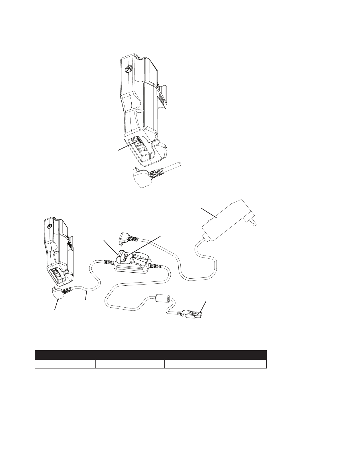
The AC power supply can plug into the oximeter (Figure 4-3) or into the WW1089 USB interface
cable (Figure 4-4).
Power Input
Connector
AC Power
Supply
Figure 4-3: AC Power Supply
AC Power Supply
(Optional)
Power Input
Connector
Connect AC Power
Here (Optional)
USB Interface
Cable to PC
USB Interface
Connect USB
Cable to Monitor
Cable
Figure 4-4: Interconnect Cable
Refer to Chapter 10: Optional Supplies & Accessories to verify the proper AC power supply for your
application. The following power supplies are suitable for use with this monitor:
CAT. NUMBER OUTPUT POWER INPUT POWER
WW1095 30 W AC power supply 100-240 VAC 50 - 60Hz
WARNING! Only use a power supply intended for use with this monitor. Use of an
inappropriate power supply may cause a patient shock hazard or cause the
oximeter to stop monitoring.
CAUTION! Use only the interconnect cables specically intended for use with this device.
See Chapter 10: Optional Supplies & Accessories, for ordering information.
Clinician’s Operation Manual 4-5
Page 30
Chapter 4: Operating Instructions
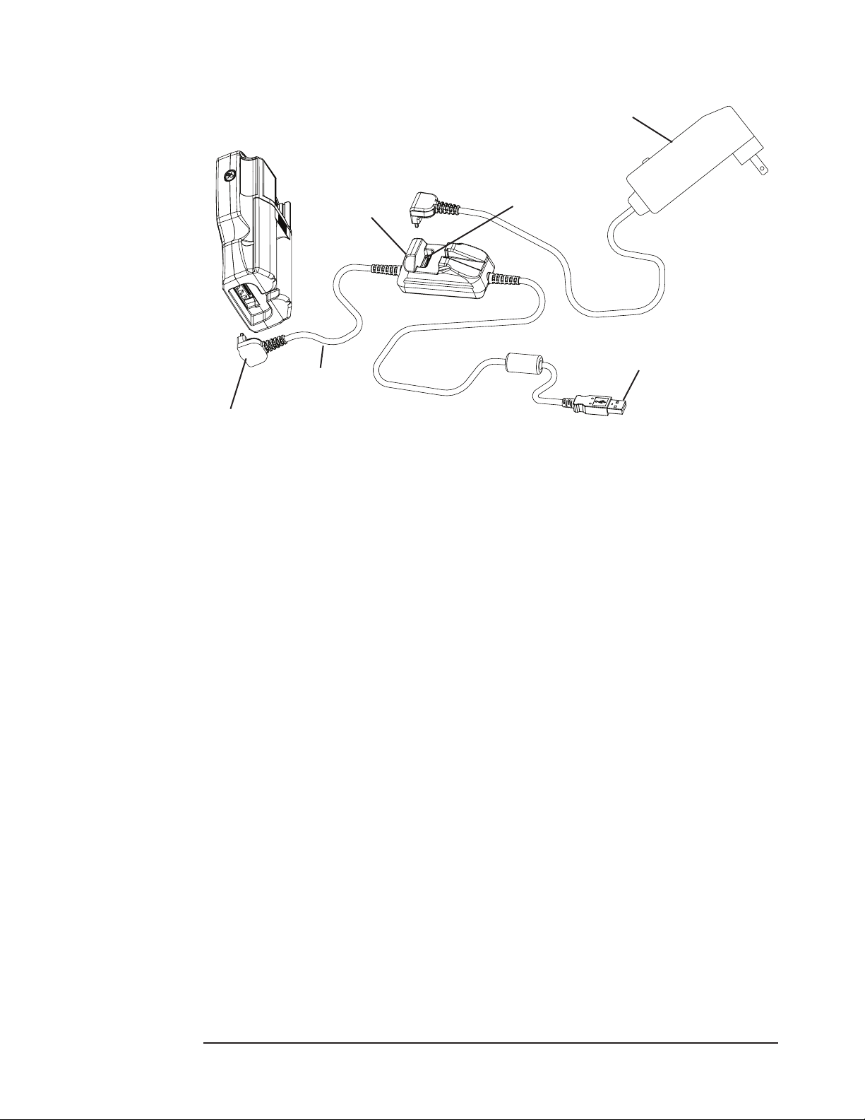
USB Power (Universal Serial Bus)
AC Power Supply
(Optional)
Power Input
Connector
USB Interface
Cable
Connect USB
Cable to Monitor
The oximeter may be powered from an external USB source such as a laptop computer or
powered USB hub. The WW1089 USB Interface Cable is a custom cable used to connect the
oximeter or docking station to an external computer via its USB port. See Chapter 7: Connecting to
a PC for more information. This port can supply a source of operating power to the oximeter.
NOTE! The WW1090 Lithium-Ion (Li+) Rechargeable Battery Pack can be fast charged by
installing it in the oximeter and supplying power, using the AC Power Supply either
directly or through the Docking Station. The WW1090 Li+ Rechargeable Battery
Pack can also be fast charged by installing it directly in the Docking Station and
supplying power using the AC Power Supply.
Figure 4-5: USB Power to Oximeter
Connect AC Power
Here (Optional)
USB Interface
Cable to PC
NOTE: To slow charge the WW1090 Lithium-Ion (Li+) Rechargeable Battery Pack, install the
Battery Pack in the oximeter and connect to USB power. Slow charging may take 20
hours or more. USB power cannot charge the spare Li+ Rechargeable Battery Pack
in the Docking Station.
4-6 Clinician’s Operation Manual
Page 31
Chapter 4: Operating Instructions
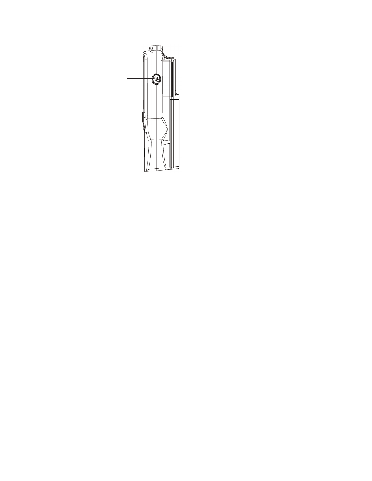
Turning On the Monitor
Press this key to turn
the monitor on and o.
Figure 4-6: Turning On the Monitor
To turn on the monitor, press the x key. Before using the monitor, check the following at powerup:
All LEDs light.•
The monitor’s software revisions (main, battery PIC, oximeter) are momentarily displayed.•
The patient record number is momentarily displayed. •
After a few seconds the % SpO2 value, pulse rate, pulse signal strength and PI bar graphs should
be shown. If not, see Chapter 9: Troubleshooting for help.
WARNING! Verify that all LEDs (light emitting diodes) on the display light up upon startup
of the device.
If the oximeter detects an error during power up, “
the display. A numeric error code will display in the SpO2 section. See Chapter 9: Troubleshooting
for more information.
” will display in the pulse rate section of
ERR
Clinician’s Operation Manual 4-7
Page 32

Chapter 4: Operating Instructions
Checking the Monitor’s Conguration
While turning the monitor on, hold the x key until
while
NOTE! If the x key is held for about 15 seconds or more,
Conguration settings are:
While the language setting is displayed, successive x key presses will cycle through the language
selections:
is ashing to see a list of conguration settings.
[lr
TREND DATA WILL BE CLEARED!
Auto Shutoff ( •
LED Brightness ( •
Trend Interval ( •
Oximeter High Sensitivity ( •
Oximeter Averaging ( •
Language - ( •
English ( •
French / Français ( •
German / Deutsch ( •
Spanish / Español ( •
Italian / Italiano (•
Continental Portuguese / Português ( •
Brazilian Portuguese / Português - Brasil ( •
Swedish / Svenska ( •
Dutch / Nederlands ( •
En
), default = no;
as
), default = 8 (of 10);
db
), default = 4 seconds;
se[
aug
) - User selectable
lan
) - default
)
fr
de
es
)
it
sd
nl
) - WW1020 only, default = off
ks
) - WW1020 only, default = 8 seconds pulse rate, 8 beat SpO2;
)
)
pt
)
)
)
br
starts to ash, then release the key
[lr
will stop ashing and
[lr
)
Stop pressing the key when the desired language is selected. After ve (5) seconds, normal
monitoring mode resumes.
Checking the Monitor’s Performance
Pulse oximeters do not require user calibration. If checking the function of the device is desired,
an Oximetry Patient Simulator (Smiths Medical PM, Inc. catalog number 1606) is available as an
accessory. The simulator attaches to the oximeter in place of the sensor. It provides a known SpO2
and pulse rate signal to the oximeter.
NOTE: A Patient Simulator does not calibrate the monitor. The monitor does not require
calibration. A Patient Simulator provides a known SpO2 value and pulse rate to the
monitor that allows the monitor’s performance to be checked.
NOTE: A Patient Simulator cannot be used to assess the accuracy of a pulse oximeter and/
or sensor.
NOTE: f Follow the instructions included with the Patient Simulator.
4-8 Clinician’s Operation Manual
Page 33

Chapter 4: Operating Instructions
Attaching the Sensor to the Patient
To attach the sensor to the patient:
Choose the appropriate sensor. See sensor table for additional information.1.
If using a reusable sensor, clean or disinfect the sensor per 2. Cleaning or Disinfecting the Sensors
section in this chapter. ( 7 Disposable sensors are for single-patient use and do not require
cleaning or disinfecting.)
Check the sensor and oximetry cable for damage and integrity. See 3. Checking the Sensor and
Oximetry Cable section for additional information.
Attach sensor to the patient.4.
WARNING! Prolonged use or the patient’s condition may require changing the sensor site
periodically. Change sensor site and check skin integrity, circulatory status, and
correct alignment at least every 4 hours.
WARNING! When attaching sensors with Microfoam® tape, do not stretch the tape or
attach the tape too tightly. Tape applied too tightly may cause inaccurate
readings and blisters on the patient’s skin (lack of skin respiration, not heat,
causes the blisters).
WARNING! SpO2 measurements may be adversely aected in the presence of high ambient
light. Shield the sensor area (with a surgical towel, for example) if necessary.
WARNING! Dyes introduced into the bloodstream, such as methylene blue, indocyanine
green, indigo carmine, patent blue V (PBV), and uorescein, may adversely
aect the accuracy of the SpO2 reading.
WARNING! Optical cross-talk can occur when two or more sensors are placed in close
proximity. It can be eliminated by covering each site with an opaque material.
WARNING! Remove ngernail polish or false ngernails before applying SpO2 sensors.
Fingernail polish or false ngernails may cause inaccurate SpO2 readings.
WARNING! Signicant levels of dysfunctional hemoglobins, such as carboxyhemoglobin
(with CO-poisoning) or methemoglobin (with sulfonamide therapy), will aect
the accuracy of the SpO2 measurement.
WARNING! Tissue damage may result from overexposure to sensor light during
photodynamic therapy with agents such as verteporphin, pormer sodium,
and metatetrahydroxyphenylchlorin (mTHPC). Change the sensor site at least
every hour and observe for signs of tissue damage. More frequent sensor site
changes/inspections may be indicated depending upon the photodynamic
agent used, agent dose, skin condition, total exposure time or other factors.
Use multiple sensor sites.
Clinician’s Operation Manual 4-9
Page 34

Chapter 4: Operating Instructions
Choosing the Sensor
WARNING! Use only SpO2 sensors and cables supplied with, or specically intended for use
with, this BCI® oximeter. Use of sensors not intended for use with this device
may cause inaccurate readings.
WARNING! Incorrectly applied sensors may give inaccurate readings. f Refer to the
sensor insert for proper application instructions.
Choose the appropriate sensor from the following chart. Select the sensor based on the patient’s
size, available application site, attachment method and other pertinent clinical information.
See the sensor’s instruction insert for detailed attachment methods and other important
f
information.
BCI® Sensors
PATIENT SITE DESCRIPTION
Adult
over 45 kg
Finger
3044: Sensor, Reusable, Adult
3044S: Spot Check Sensor, Reusable, Adult
3444: Sensor, Reusable, Comfort Clip
®
Finger or Toe
Ear
Pediatric
15-45 kg
Infant
3-15 kg
All Extension Cable 3311: Cable, Oximetry 1.5 meters (5 feet)
NEONATE SENSORS FOR THE WW1020 ONLY
Neonate
under 3 kg
SMALL INFANT SENSORS FOR THE WW1000 ONLY
Small Infant *
under 3 kg
*The BCI® 1302 and 3026 oximetry sensors should not be used on neonatal patients with the
WW1000 monitor. Testing has not been conducted for the WW1000 for patients less than 30 days
old. These sensors may, however be used on older patients.
Finger
Finger or Toe
Ear
Hand or Foot
Toe
Finger or Toe
Hand or Foot
Foot
Hand or Foot
Foot
3043: Sensor, Reusable, Universal ‘Y’
1300: Sensor, Disposable, Adult Finger
WW3078: Sensor, Reusable, Ear
3044: Sensor, Reusable, Adult (>20 kg)
3044S: Spot Check Sensor, Reusable, Adult
3444: Sensor, Reusable, Comfort Clip
3178: Sensor, Reusable, Pediatric Finger (5-45 kg)
3178S: Spot Check Sensor, Reusable, Pediatric
3043: Sensor, Reusable, Universal ‘Y’
1301: Sensor, Disposable, Pediatric Finger 7
WW3078: Sensor, Reusable, Ear
3043: Sensor, Reusable, Universal ‘Y’
3025: Sensor, Reusable, Wrap, Infant
1303: Sensor, Disposable, Infant 7
1302: Sensor, Disposable, Neonate/Small Infant 7
3026: Sensor, Reusable, Wrap, Neonate/Small Infant
1302: Sensor, Neonate/Small Infant (disposable)
3026: Sensor, Wrap, Neonate/Small Infant (reusable)
7
®
7
4-10 Clinician’s Operation Manual
Page 35

Chapter 4: Operating Instructions
Nellcor® Sensor (WW1020 Only)
PATIENT SITE DESCRIPTION
Adult
over 45 kg
Finger DS100A nger sensor (reusable)
Cleaning or Disinfecting the Sensors
Clean or disinfect reusable sensors before attaching to a new patient.
WARNING! Unplug the sensor from the monitor before cleaning or disinfecting.
WARNING! Do not autoclave, ethylene oxide sterilize, or immerse the sensors in liquid.
Clean the sensor with a soft cloth moistened in water or a mild soap solution. To disinfect the
sensor, wipe the sensor with a 70% isopropyl alcohol solution. If there is contamination with
blood borne pathogens (BBPs) or other potentially infectious materials (OPIMs), then the use of a
facility approved disinfectant of appropriate spectrum for the suspected organisms is appropriate.
CAUTION! Do not immerse the sensor in any liquid.
CAUTION! Cleaning with disinfectants, including alcohol, may shorten the life of the plastic
or electronic parts, but appropriate disinfection must still be performed.
Checking the Sensor and Oximetry Cable
Follow these instructions each time before you attach the sensor to the patient. This helps ensure
the sensor and oximetry cable are working properly.
WARNING! Using a damaged oximetry sensor or cable may cause inaccurate readings.
Inspect each sensor and cable. If a sensor or cable appears damaged, do
not use it. Use another sensor or cable or contact your authorized service
representative for help.
WARNING! Do not use more than one Oximetry Extension Cable. The monitor may fail to
operate properly if multiple Oximetry Extension Cables are connected together.
WARNING! Misuse or improper handling of the sensor and cable may result in damage to
the sensor. This may cause inaccurate readings.
Before the sensor is attached, check the integrity of the sensor and cable.1.
If not using the oximetry extension cable, connect the sensor to the oximeter. Push the 2.
sensor’s connector rmly into the oximeter.
If using the oximetry extension cable, connect the sensor to the cable and the cable to the
oximeter. Push the cable connector rmly into the oximeter.
Make sure the red light in the sensor is illuminated.3.
Now the sensor can be attached to the patient.4.
WARNING! If any of the integrity checks fail, do not attempt to monitor the patient. Use
another sensor or oximetry extension cable, or contact the authorized service
representative for help if necessary.
NOTE: Obstructions or dirt on the sensor’s red light or detector may cause checks to fail.
Make sure there are no obstructions and the sensor is clean.
Clinician’s Operation Manual 4-11
Page 36
Chapter 4: Operating Instructions
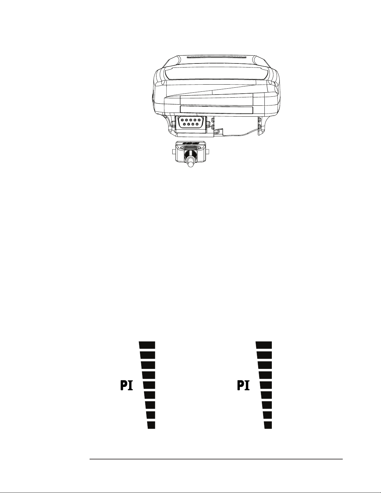
Hold the connector rather than the cable when connecting or disconnecting the nger sensor to
the device.
Figure 4-7: Disconnecting or Connecting the Finger Sensor to the Device
Do not use excessive force or unnecessary twisting when connecting, disconnecting, storing, or
when using the sensor.
Pulse Amplitude Index
The Pulse Amplitude Index (PI) bar graph can be useful in assessing the relative quality of the
chosen sensor site. The PI value is a relative measure of pulse-signal strength over time at a
pulse oximeter monitoring site, and is non-pulsatile in nature. Pulse Amplitude Index is dened
as PI = (100 * AC)/DC where AC is the alternating current (pulsatile component of the signal) and
DC is direct current (non-pulsatile component of the signal).
The PI value is represented as a 9-segment bar graph. The more bars lit, the higher the PI value,
and generally the better the sensor site. If only the rst one or two segments are lit, the segment
color changes to yellow, indicating a technical alert condition. This indicates that the oximeter is
receiving a low signal quality from that sensor site, and further degradation of the signal quality
could cause the oximeter to lose its ability to obtain readings. A dierent sensor site should be
considered.
The PI value approximately maps to a 9-segment bar graph as shown below. The two lowest bars
(1 and 2) are bi-color (yellow and green), and bars 3 through 9 are green.
10.24 - 20.47
5.12 - 10.23
2.56 - 5.11
1.28 - 2.55
0.64 - 1.27
0.32 - 0.63
0.16 - 0.31
0.08 - 0.15
0.00 - 0.07
>10.2
>5.0 - 10.2
>2.6 - 5.0
>1.2 - 2.6
>0.6 - 1.2
>0.4 - 0.6
>0.2 - 0.4
>0 - 0.2
0.00
For the WW1020 Oximeter
For the WW1000 Oximeter
NOTE! The PI value is a relative value that varies from patient to patient.
4-12 Clinician’s Operation Manual
Page 37

Chapter 4: Operating Instructions
When placing the sensor on the patient, allow the cable to lay across the top of the hand and
parallel to the arm of the patient as shown in Figure 4-8.
1
2
Figure 4-8: Positioning the Cable of the Finger Sensor
1
Sensor (nger sensor shown for illustration only)
2
Cable
Clinician’s Operation Manual 4-13
Page 38
Chapter 4: Operating Instructions
Storing the Sensor
Upon completion of patient monitoring, detach the sensor and loosely coil the nger sensor
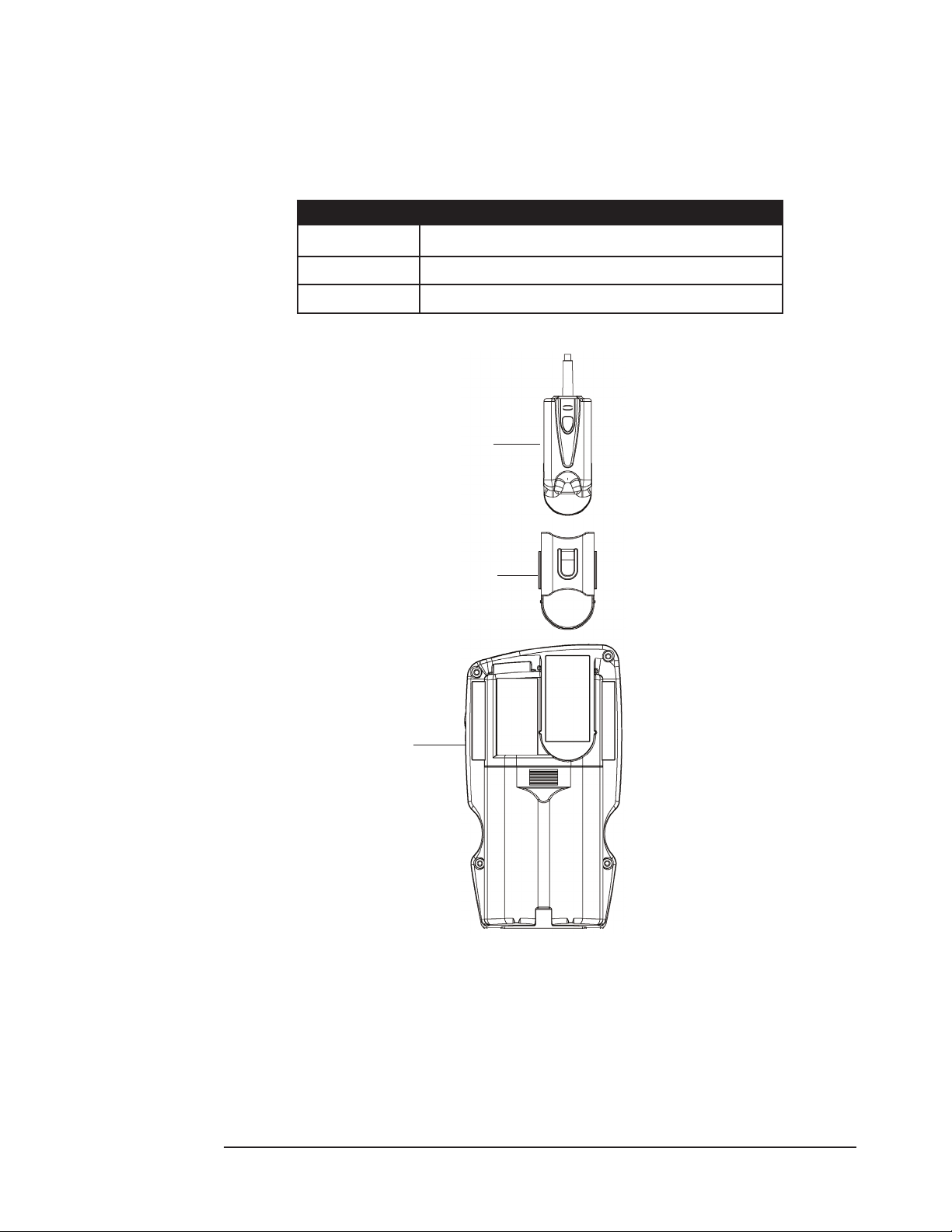
cable. Store the sensor in the Sensor Storage cradle or other safe place when not in use. Use the
proper cradle. Three dierent sensor cradles are available for this oximeter.
CRADLE SENSOR TYPE
1 Should be used for BCI® pediatric size nger sensors
2 Should be used for the 3444 Comfort Clip® sensor
3 Should be used for the BCI® adult size nger sensors
Sensor
Sensor Cradle
Oximeter
Figure 4-9: Attaching the Sensor and Sensor Cradle to the Monitor
4-14 Clinician’s Operation Manual
Page 39
Chapter 4: Operating Instructions
Home Use
WARNING! This device is intended for use by persons trained in professional health care or
those who have access to the oversight of a professional health care provider.
The operator must be thoroughly familiar with the information in this manual
before using the device.
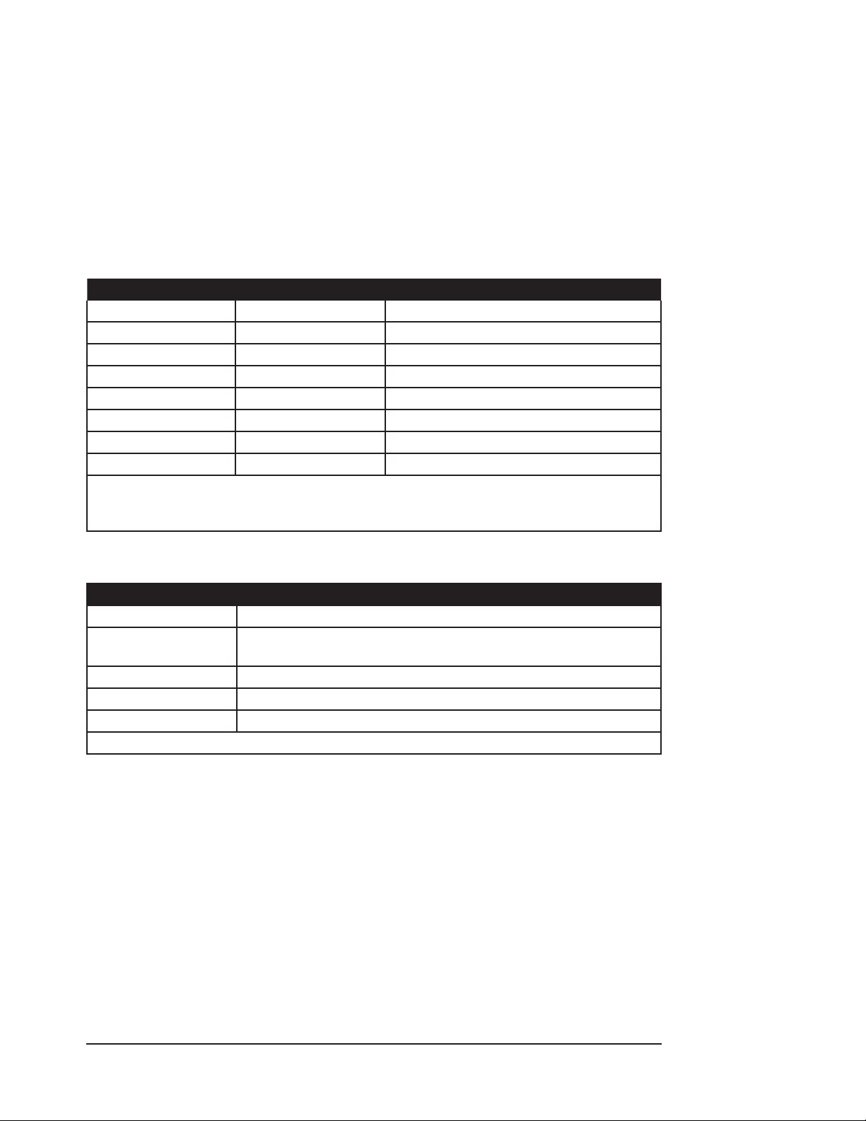
Equipment and Supplies Checklist for Home Use
Provide the following to the home use caregiver:
QUANTITY CAT. NO. DESCRIPTION
1 WW1020 or WW1000 Oximeter with AA batteries
1 WW1095 Universal AC mains adapter - 30W
1 WW1025 Docking Station (optional)
1 WW1090 Li-Ion rechargeable battery pack (optional)
1 3311 Oximeter Cable, 1.5 meters (5 feet)
* * Oximetry Sensor
* * Oximetry Sensor Attachments
1 31169B88 WW1020 / WW1000 Home Use Guide
* Note: The doctor will prescribe the type and quantity of the sensors needed for home-
use. Be sure that the proper type and quantity of sensor attachments are also
prescribed.
The home use caregiver will also need these supplies and reference materials:
QUANTITY DESCRIPTION
1 Scissors (for trimming adhesive strips or adhesive tape).
* Appropriate disinfectant and a soft, clean cloth (or alcohol wipes) for
disinfecting monitor, accessories and reusable sensor.
1 Emergency phone numbers for the doctor.
1 Emergency phone number for the hospital emergency room.
1 Phone number for equipment supplier.
* Quantity prescribed by doctor.
Clinician’s Operation Manual 4-15
Page 40

Chapter 4: Operating Instructions
Training the Home Use Caregiver
The home use caregiver must be trained in CPR. Inform the caregiver that the oximeter is not
to be used as an apnea monitor and should only be used for spot checking applications (noncontinuous use). Following this guide while teaching these tasks may help the instructor and the
caregiver.
Show the home use caregiver how to:
Connect the AC Power Supply to a wall outlet.•
Make sure the AC Power Supply outlet is not controlled by a wall switch.•
Connect AC Power Supply to the docking station or oximeter.•
Make sure the monitor’s POWER indicator is lit.•
Visually inspect the sensor and oximetry cable.•
Connect the sensor to the oximetry cable.•
Connect the oximetry cable to the monitor.•
Turn on the monitor.•
Perform a pre-use check: Verify all display LEDs turn on at power up.•
Route the cable safely from the patient to the monitor to prevent possible patient •
strangulation.
Attach the sensor(s) prescribed by the doctor.•
Measure the SpO•
Interpret the Low Battery Signal.•
Turn off the monitor if appropriate.•
Tell the caregiver how to respond:
In case of a patient emergency, including what therapy to provide the patient.•
In case the Low Battery Indicator appears.•
In case the caregiver has trouble operating the equipment.•
, pulse rate, PI and pulse signal strength bar graph readings.
2
4-16 Clinician’s Operation Manual
Page 41

Chapter 5: Patient Record Number and Trend Data
Chapter 5: Patient Record Number and Trend Data
Description
Whenever the WW1020/WW1000 is monitoring a patient, it stores an SpO2, a pulse rate, and PI
reading along with any applicable condition ags and a time stamp every four (4) seconds. The
stored readings are called trend data. The monitor can store at least 144 hours of trend data for a
combination of all 99 available patient record numbers.
Incrementing the Patient Record Number
Each time the monitor is turned on, the patient record number is displayed during the power-up
sequence. If valid trend data was collected from the previous patient, the patient record number
is incremented at power up. If no valid trend data was collected from the previous patient, the
patient record number is not incremented. For example, if the last time the oximeter was on it
displayed patient 10 (
point was saved for
Clearing Trend Data section in this chapter for information on clearing trends.
Memory Capacity
) , the next time it will be
P10
. Clearing the trend data resets the patient record number to P1. See
P10
, provided that at least one trend data
P11
The trend interval aects the maximum trend record length. The trend interval is xed at 4
seconds, and the total record length is 6 days. If the total trend record length is exceeded for all
patients combined, each new trend entry will replace the oldest overall trend entry.
Clearing Trend Data
To clear all of the trend memory and reset the patient record number to P1, turn the monitor o.
Then push and hold the on/o x key until “
is displayed. This takes about 15 seconds.
P1
If the key is released at any time before
conguration settings are displayed. (See Checking the Monitor’s Conguration section in Chapter
4 for details.)
[lr
” stops ashing in the Pulse Rate display and
[lr
stops ashing, the memory is retained, and the
Trend Data Output
Trend data may be output to a printer or PC. See Chapter 6: Optional Docking Station and Printer
for information on printing trend data. See Chapter 7: Connecting to a PC, for information about PC
output.
Clinician’s Operation Manual 5-1
Page 42

Chapter 5: Patient Record Number and Trend Data
This page is intentionally left blank.
5-2 Clinician’s Operation Manual
Page 43
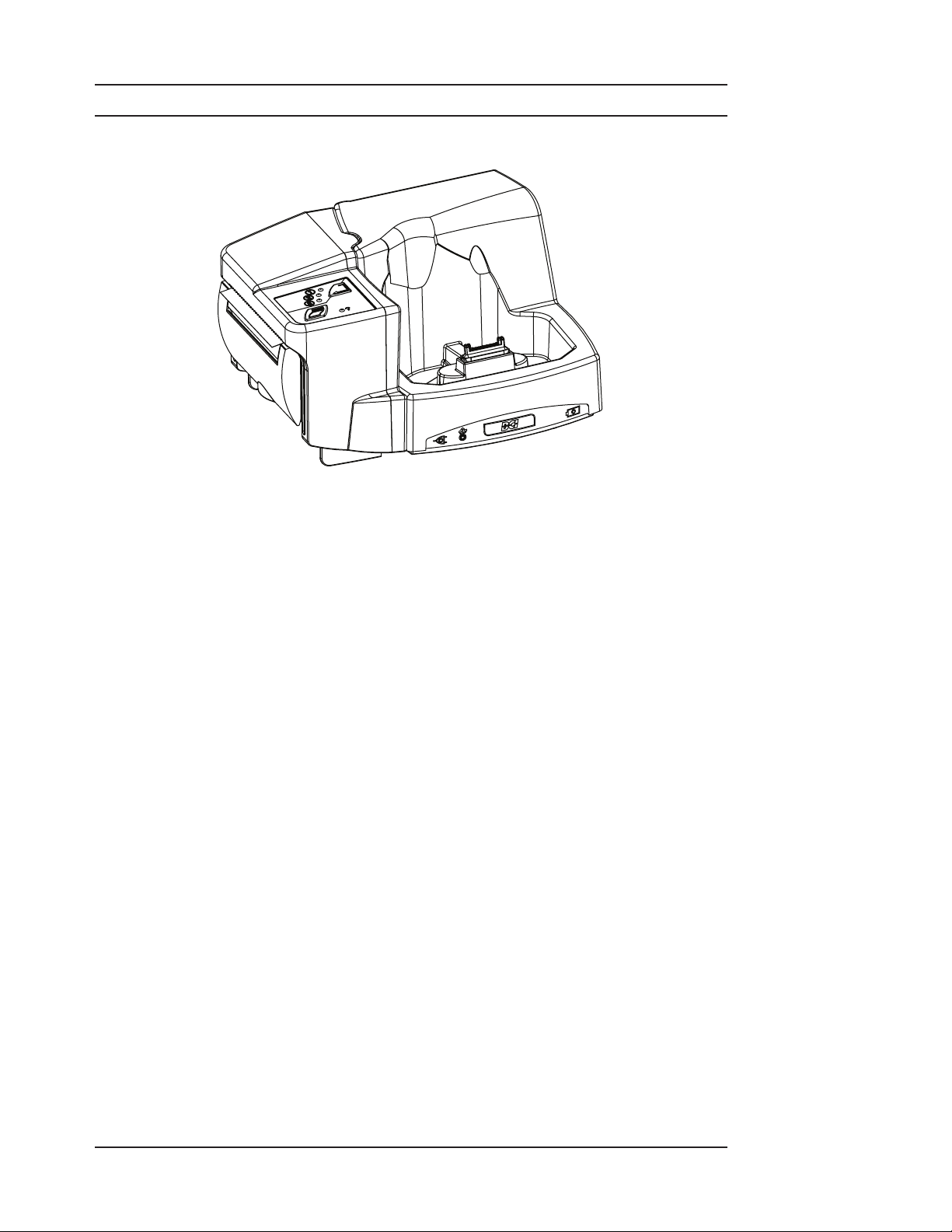
Chapter 6: Optional Docking Station and Printer
Chapter 6: Optional Docking Station and Printer
Description
Figure 6-1: Docking Station with Printer Attached
The WW1025 Docking Station serves many purposes depending on individual needs and
selection of optional equipment. The Docking Station is powered by the WW1095 AC Power
Supply, which can power the oximeter and operate the printer while charging the internal and
spare battery packs.
The Docking Station:
Provides a convenient and secure “home base” for the oximeter.•
Recharges WW1090 Lithium-Ion (Li+) rechargeable battery pack installed in the oximeter.•
Recharges an additional WW1090 Lithium-Ion (Li+) rechargeable battery pack stored in the •
Docking Station.
May be equipped with a WW1026 thermal printer.•
Allows connection to a PC for trend memory dump.•
Transfers USB power to the oximeter if no AC is connected (only when the USB interface •
cable, WW1089, is connected to an active source of USB power).
Clinician’s Operation Manual 6-1
Page 44
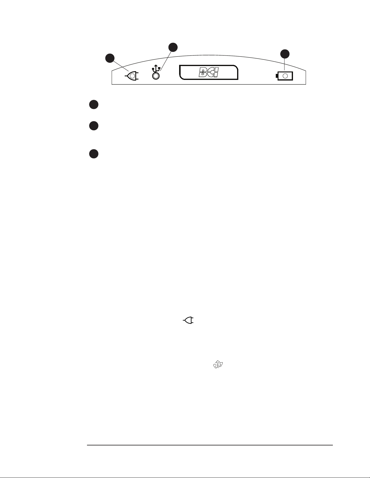
Chapter 6: Optional Docking Station and Printer
Docking Station
2
1
Figure 6-2: Indicators on Docking Station Front Panel
1
AC Power Indicator
This indicator will light when AC power is connected to the Docking Station.
2
USB Power Indicator
This indicator will light when a USB cable is connected to the Docking Station, but AC power
is not.
3
Charging Spare Battery Indicator
This indicator will ash green when the WW1090 Lithium-Ion (Li+) rechargeable battery
pack is charging. After the battery is fully charged, the indicator lights solid green. Battery or
charging errors are indicated by a yellow LED. See Chapter 9: Troubleshooting for details.
Powering the Docking Station
3
WARNING! Do not plug the Docking Station AC power supply into an outlet controlled by a
wall switch.
WARNING! Do not allow any moisture to contact the AC power supply connectors, or a
safety hazard may result. Ensure that hands are thoroughly dry before handling
the AC power supply.
WARNING! Do not place the Docking Station in the patient’s bed or crib. Do not place the
Docking Station on the oor.
WARNING! Failure to place the Docking Station away from the patient may allow the
patient to turn o, reset, or damage the monitor, possibly resulting in the
patient not being monitored. Make sure the patient cannot reach the monitor
from their bed or crib.
The WW1095 AC Power Supply provides power to the Docking Station and connected accessories.
Connect the AC Power Supply to the dock using the data port or Power Input Connector. The
Docking Station’s AC power indicator ( ) will light when AC power is connected. The Docking
Station has built-in intelligence that prioritizes available power to the oximeter, printer and
chargers. If USB power is used for the Docking Station, some accessories may not operate.
When the WW1089 USB interface cable is connected to the Docking Station, data can be
transferred from the oximeter’s data port through the Docking Station to a compatible device. If
the USB cable is used without AC power, the USB ( ) indicator is lit, and USB power is available
to the oximeter.
NOTE! The WW1090 Lithium-Ion (Li+) Rechargeable Battery Pack can be fast charged by
installing it in the oximeter and supplying power, using the AC Power Supply either
directly or through the Docking Station. The WW1090 Li+ Rechargeable Battery
Pack can also be fast charged by installing it directly in the Docking Station and
supplying power using the AC Power Supply.
6-2 Clinician’s Operation Manual
Page 45
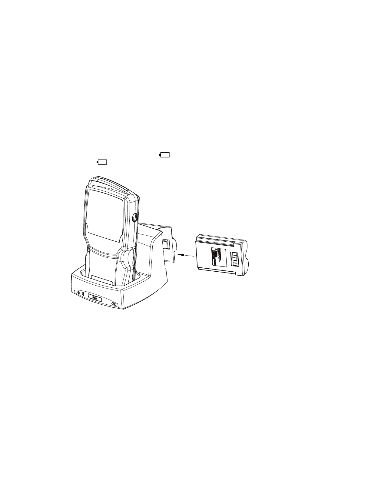
Chapter 6: Optional Docking Station and Printer
NOTE! To slow charge the WW1090 Lithium-Ion (Li+) Rechargeable Battery Pack, install the
Battery Pack in the oximeter and connect to USB power. Slow charging may take 20
hours or more. USB power cannot charge the spare Li+ Rechargeable Battery Pack
in the Docking Station.
NOTE: USB power may fail if AC power is interrupted to its PC or powered USB hub. Always
use charged batteries in the oximeter.
WW1090 Lithium-Ion (Li+) Rechargeable Battery Pack
The Docking Station (when powered by the WW1095 AC Power Supply) will charge two WW1090
Lithium-Ion (Li+) rechargeable battery packs simultaneously. It will recharge the currently
installed oximeter battery pack as well a spare pack mounted in the Docking Station battery
charger.
The WW1090 Lithium-Ion (Li+) rechargeable battery pack is placed in the dock as shown in gure
6-3. When the battery is charging, the indicator ( ) ashes green. After the battery is fully
charged, the indicator ( ) lights solid green. Battery or charging errors are indicated by a
yellow LED. See Chapter 9: Troubleshooting for details.
Figure 6-3: Connecting the Rechargeable Battery Pack
NOTE: The battery in the Docking Station battery charger cannot power the oximeter
without being installed in the oximeter. In the event of loss of power to the Docking
Station, the spare battery will not automatically provide power.
Installing the Oximeter to the Dock
The WW1020/WW1000 is placed bottom rst into the Docking Station facing out as shown in
gure 6-3. Conrm that good connection is made by observing that the oximeter’s external power
indicator (X) is lit.
Downloading Data to PC
Data may be sent to a computer through the Docking Station using the WW1089 USB Interface
Cable. See Chapter 7: Connecting to a PC for details.
Clinician’s Operation Manual 6-3
Page 46
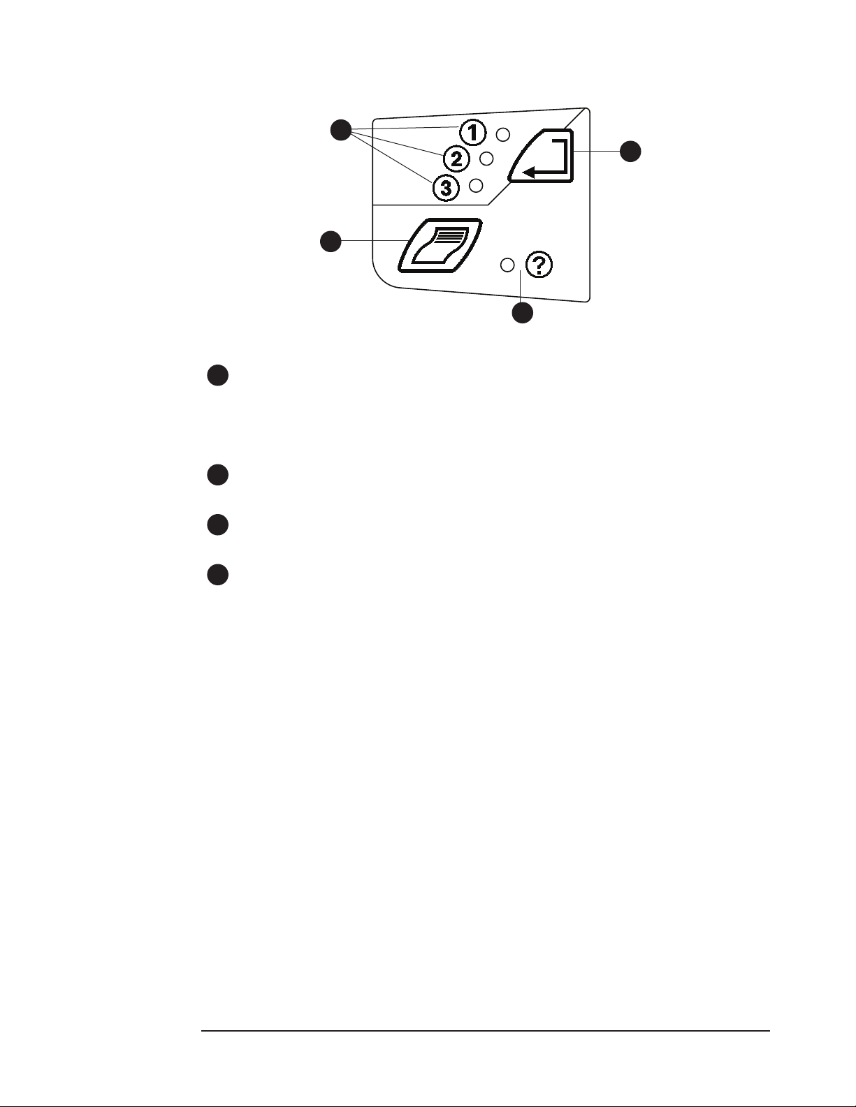
Chapter 6: Optional Docking Station and Printer
Printer
1
4
2
3
Figure 6-4: Printer Keys and Indicators
1
Print Mode Indicators
These indicators light according to what print mode is selected. See Choosing the Print Mode
section later in this Chapter.
The Print Mode Indicator will blink green when printing is pending or in progress.
2
Start/Stop Print Key
Press this key to start or stop printing.
3
Print Error Indicator
This indicator will light if there is an error in printing.
4
Select Print Mode Key
Press this key to change the print mode.
6-4 Clinician’s Operation Manual
Page 47
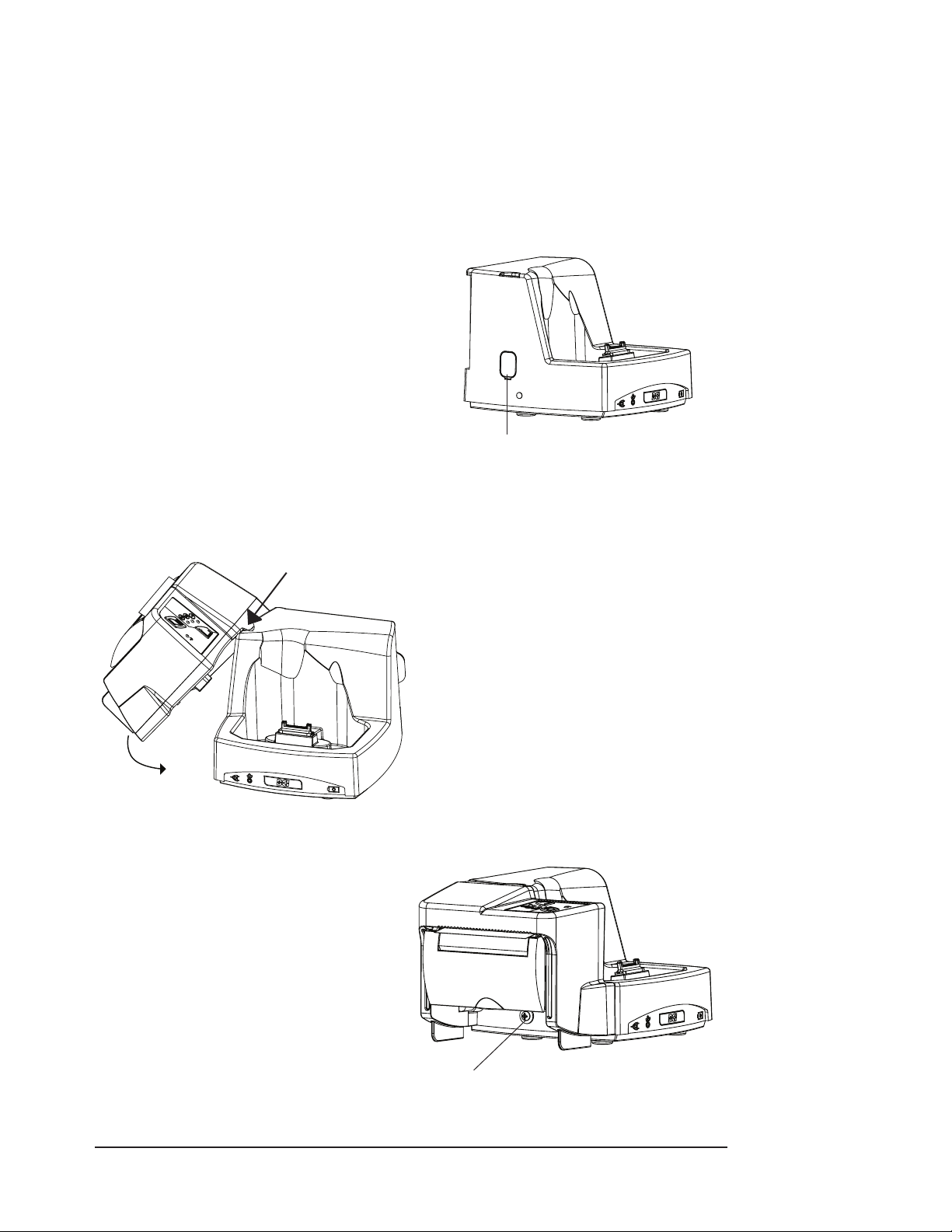
Chapter 6: Optional Docking Station and Printer
Attaching the Printer
The optional WW1026 thermal printer attaches to the Docking Station with a single screw as
shown in Figure 6-5C. Follow the steps below.
WARNING! The Docking Station must have a Printer or Printer Port Cover installed. Failure
to do so may cause a risk of electrical shock to the patient or operator or risk
damage to the equipment.
To attach the printer to the Docking Station:
Remove the oximeter and battery and
1.
disconnect any cable from the Docking
Station.
NOTE: Failure to remove the oximeter and
battery from the Docking Station
prior to installing the printer will
result in an error which may cause a
faulty printout.
Remove the Docking Station printer port 2.
cover.
Remove port cover using a screwdriver
Figure 6-5A: Remove the Docking Station Printer Port Cover
Hook the tab on the
top of the printer to the
Docking Station here.
Figure 6-5B: Align and Connect the Dock and Printer
Install the screw as shown in gure 6-5C.
4.
Reconnect any cables and replace the 5.
oximeter and battery.
3.
Hook the tab on the top of the printer
to the groove at the top of the Docking
Station. Then swing the printer down to
align and attach the printer to the dock’s
electrical connectors.
The printer is now ready to load paper.6.
Install screw here
Figure 6-5C: Mate and Align the Dock and Printer
Clinician’s Operation Manual 6-5
Page 48
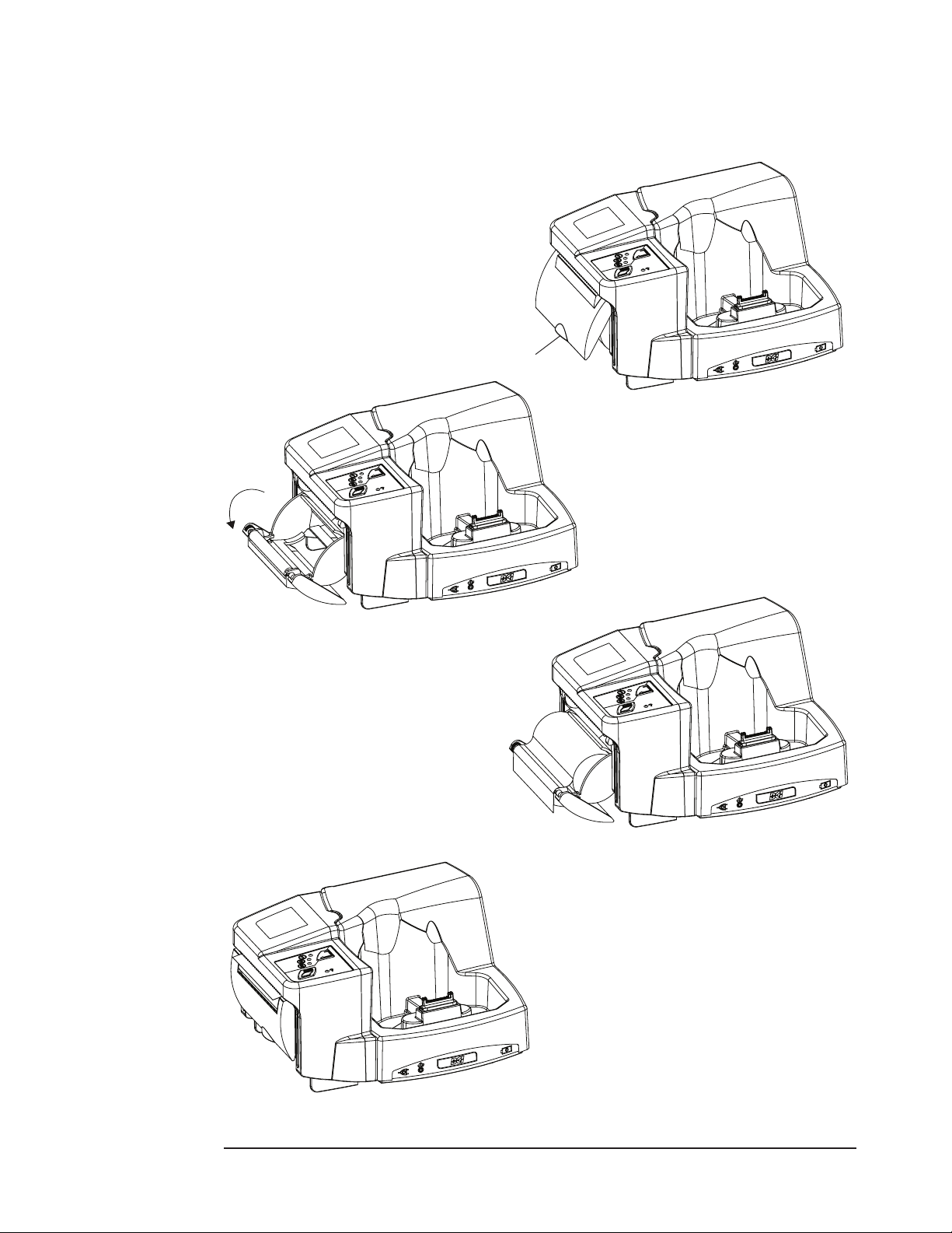
Chapter 6: Optional Docking Station and Printer
Loading Paper
The printer uses 58mm wide thermal paper. See Chapter 10: Optional Supplies & Accessories for part
number and ordering information. To load the paper, follow the steps illustrated below.
Release printer door by lifting clear cover.1.
Lift here
Figure 6-6A: Release Printer Door
Swing open paper holder by 2.
continuing to pull on clear door.
Figure 6-6B: Swing Open Paper Holder
Place paper spool in holder so that 4.
the paper exits over the top of the
roll and drapes over the rubber
roller as shown in gure 6-6C.
Remove existing spool if present.3.
Figure 6-6C: Place Paper Spool in Holder
Close the paper holder door and the clear 5.
cover.
Tear o any excess paper by pulling the 6.
paper up toward the front of the printer.
The printer is now ready to use. 7.
Figure 6-6D: Close Paper Holder Door and Clear Cover
6-6 Clinician’s Operation Manual
Page 49
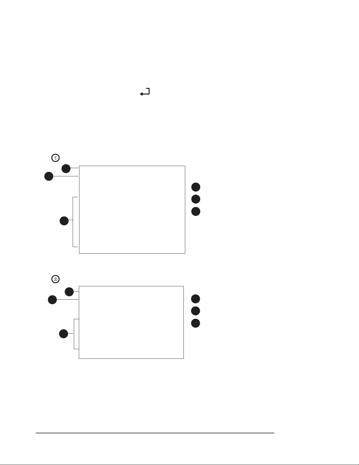
Chapter 6: Optional Docking Station and Printer
Choosing the Print Mode
Data can be printed in real time, numeric trend or graphic trend modes. In either trend mode,
6 days of previously stored data (depending on trend interval) collected from 1 to 99 patients
can be printed. See Chapter 5: Patient Record Number and Trend Data. The printer select key sets
the printer mode in the oximeter. When a new oximeter is installed in the Docking Station, it may
have a dierent print format. Always check the printer format prior to pushing the start key.
Change modes by pushing the select key ( ) until the desired mode is lit.
To start printing, push the print (F ) key. The Print Mode Indicator on the printer will blink green
when printing is pending or in progress.
NOTE: The oximeter must be installed in the Docking Station to print.
NOTE: Thermal paper must be installed.
Mode 1 - Real Time Mode prints data every 5 seconds. See gure 6-7.
1
REALTIME DATA
2
3
ID:001________________
hh:mm:ss SpO2 Rate PI
(%) (bpm) (%)
00:26:35 95% 75 bpm 5.4%
00:26:40 95% 75 bpm 5.6%
00:26:45 95% 75 bpm 5.4%
00:26:50 95% 75 bpm 5.6%
00:26:55 95% 75 bpm 5.6%
00:27:00 95% 75 bpm 5.6%
00:27:05 95% 75 bpm 5.6%
1
Title
2
Patient Record Number
3
Real time %SpO2, pulse
rate and PI values printed
every 5 seconds
Figure 6-7: Sample Real Time Data Log
Mode 2 - Numeric Trend Data prints in a tabular form. See gure 6-8.
TREND DATA
1
2
ID: 009________________
hh:mm:ss SpO2 Rate PI
(%) (bpm) (%)
00:11:40 96% 93 bpm 7.5%
3
00:11:36 96% 94 bpm 8.3%
00:11:32 96% 90 bpm 8.8%
1
2
3
00:11:28 96% 89 bpm 9.2%
Figure 6-8: Sample Numeric Trend Data
Title
Patient Record Number
Trended %SpO2, pulse rate
and PI values printed every
4 seconds
Clinician’s Operation Manual 6-7
Page 50
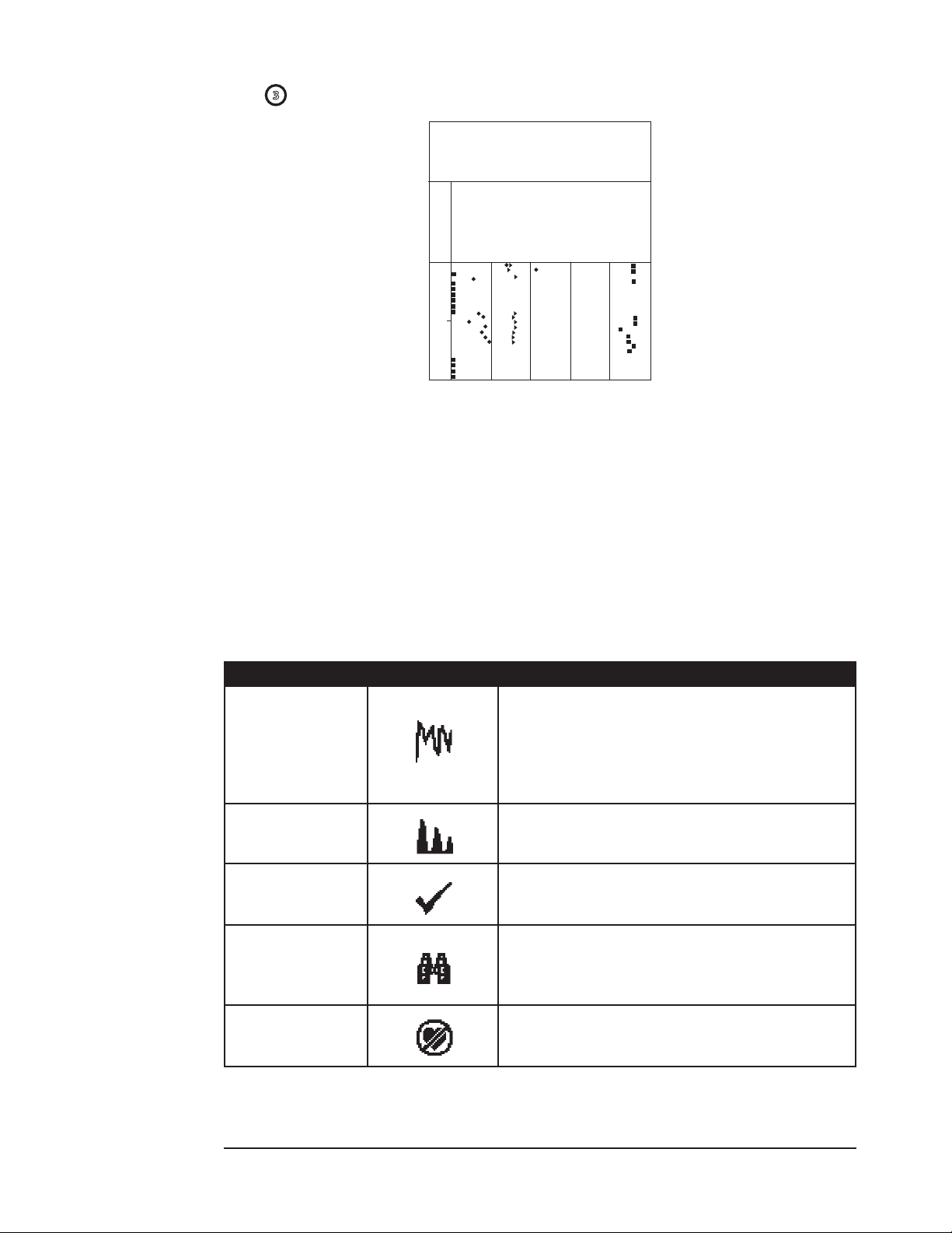
Chapter 6: Optional Docking Station and Printer
Mode 3 - Graphic Trend Mode prints in a chart format See gure 6-9.
TREND DATA
ID: 009______________________
Trend Time Scale=20 Sec/Point
0
...........PI...........
0
► ► ► ► ►
Pulse Rate(bpm) ► ► ► ► ►
50
▪ ▪ ▪ ▪ ▪ ▪ ▪
04
00:08 00
Figure 6-9: Sample Graphic Trend
SpO2(%)▪ ▪ ▪ ▪ ▪ ▪ ▪
20
254
100
NOTE! While printing trends, the printer will pause for approximately 20 seconds after
10 seconds of printing. This allows the thermal print head to cool. A small gap may
appear on each printout when printing resumes.
NOTE! Invalid SpO2 data and SpO2 values between 0 and 50 will be printed as 50.
Trend Data Condition Flags
Each time a trend interval occurs and data is stored, certain conditions, active at that time, are
stored with the data. These are indicated by symbols on the print out.
CONDITION SYMBOL DESCRIPTION
Artifact indicator informs user of excess motion,
noise or other signal information that the algorithm
Artifact
(WW1020 only)
Small Pulse
(WW1020 only)
Check Sensor
Searching too Long
Lost Pulse
interprets as potentially non-physiological.
This ag is an indicator that pulse rate data has
changed and now may be invalid.
Indicates the signal strength is ≤ 3.
Indicates a problem with sensor placement or that no
sensor is plugged into the sensor connector. No valid
parameter data is available.
Only displayed if the oximeter has not detected a
valid pulse at any time after power up. Indicates that
the oximeter has searched for more than 20 seconds
but no pulse was detected.
Indicates the oximeter has searched for more than
20 seconds, a nger is detected in the sensor, but a
previously detected pulse is no longer present.
6-8 Clinician’s Operation Manual
Page 51
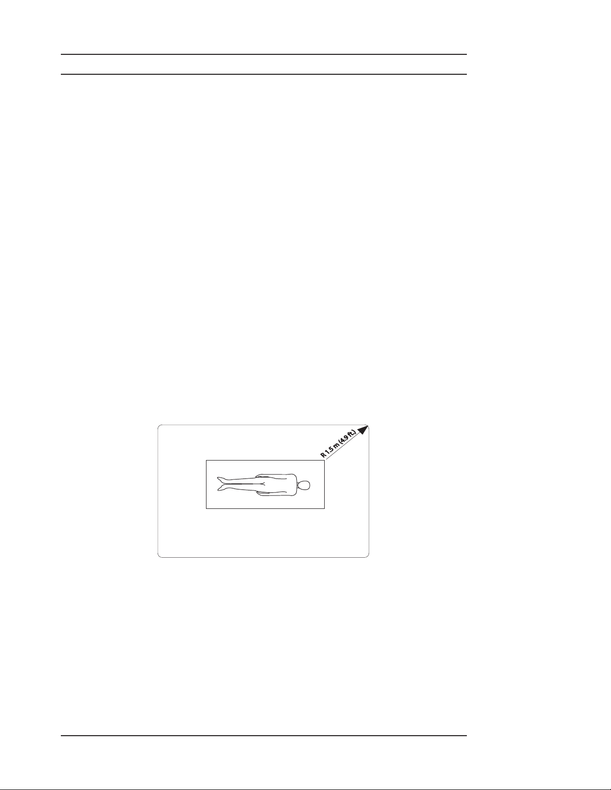
Chapter 7: PC Communication Setup
R 1.5 m (4.9 ft.)
Chapter 7: PC Communication Setup
Description
Real Time and Trend Data may be sent to a PC from the oximeter in the following ways:
The Data/Power Connector of the oximeter or of the Docking Station may be connected to •
a PC using the USB Interface Cable (< WW1089). Trend data or Real Time patient data will
be downloaded using a proprietary data protocol.
The oximeter sensor can be replaced with the WW3350 or 3339 cable to transfer comma-•
separated value (.CSV) ASCII Trend Data via RS232.
WARNING! When connecting this monitor to any instrument, verify proper operation
before clinical use. Refer to the instrument’s user manual for full instructions.
Accessory equipment connected to the monitor’s data interface must be
certied according to the respective IEC standards, i.e., IEC 60950 for data
processing equipment or IEC 60601-1 for electromedical equipment. All
combinations of equipment must be in compliance with IEC 60601-1-1 systems
requirements. Anyone connecting additional equipment to the signal input
port or the signal output port congures a medical system, and, therefore,
is responsible that the system complies with the requirements of the system
standard IEC 60601-1-1.
WARNING! IEC 60950 approved equipment must be placed outside the “patient
environment”. The patient environment is dened as an area 1.5 m (4.92 feet)
from the patient.
PATIENT ENVIRONMENT
Clinician’s Operation Manual 7-1
Page 52
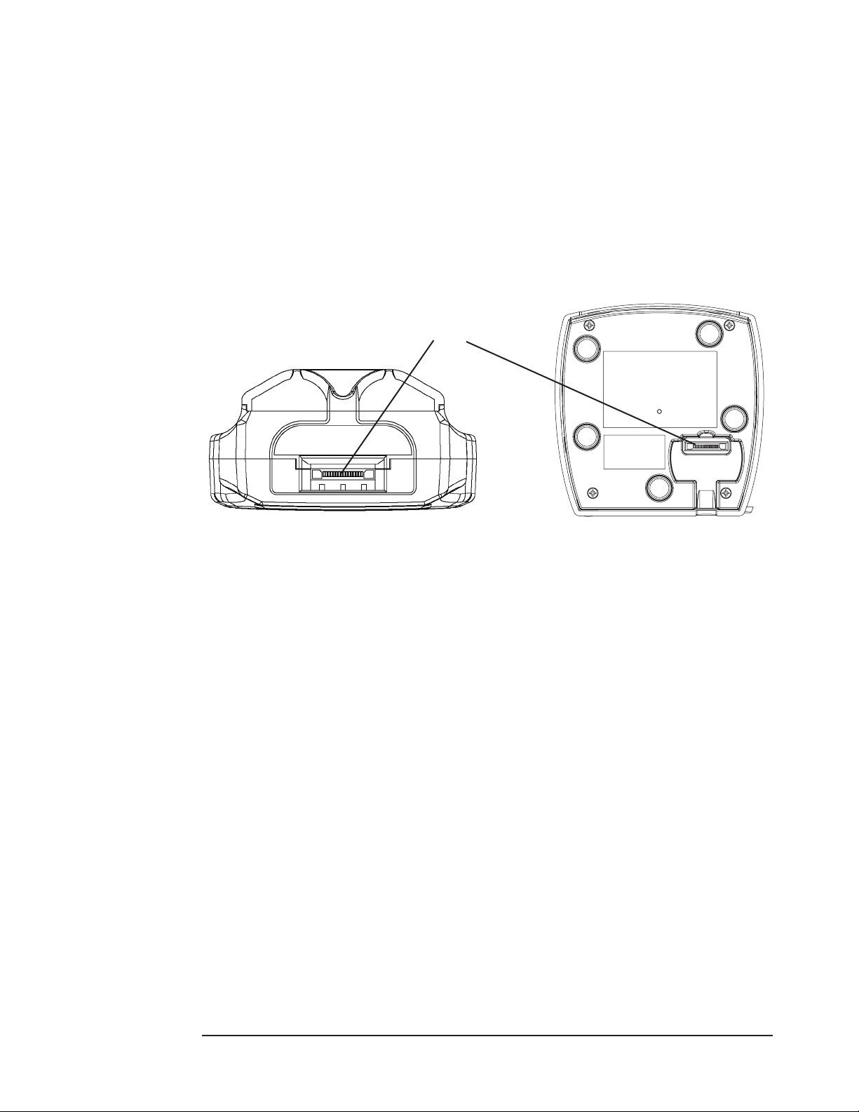
Chapter 7: PC Communication Setup
Power Input and Data Connector Port
Data can be transferred to a computer running software that is compatible with the specialized
data format BCICP1030 by using the USB Interface Cable.
The following items will be needed:
Oximeter with or without the Docking Station•
User Compatible PC Application Software•
USB Interface Cable (• < WW1089)
AC Power Supply (optional)•
Data/Power Input Connector
Figure 7-1A: Bottom Panel of Oximeter
Figure 7-1B: Bottom Panel of Docking Station
7-2 Clinician’s Operation Manual
Page 53
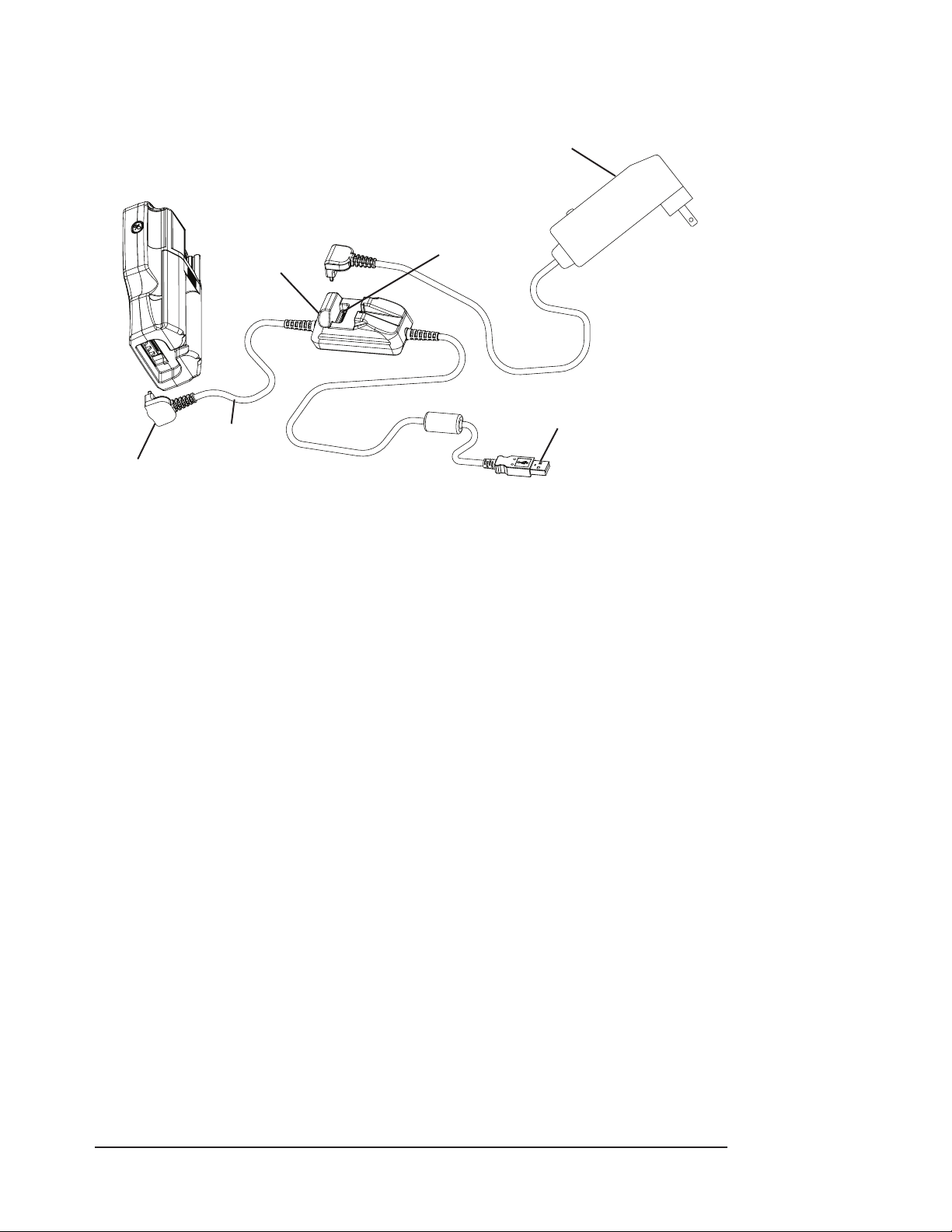
How to Set Up Equipment
Chapter 7: PC Communication Setup
Refer to Figure 7-2 for the cable connections.
Power Input
Connector
USB Interface
Cable
Connect USB
Cable to Monitor
Figure 7-2: Connecting to a PC using USB Interface Cable
Connect the USB interface cable to the I / O or Power Input Connector on the oximeter or 1.
Docking Station.
AC Power Supply
(Optional)
Connect AC Power
Here (Optional)
USB Interface
Cable to PC
If using the WW1095 AC Power Supply, connect it to the PC cable power input connector.2.
Connect the interface cable to the PC’s USB port.3.
The oximeter is now ready to download data. 4.
The BCICP1030 data output format is available upon request.
NOTE!
Review the PC communication program’s instructions to determine how to
1
save the data to the PC.
Clinician’s Operation Manual 7-3
Page 54
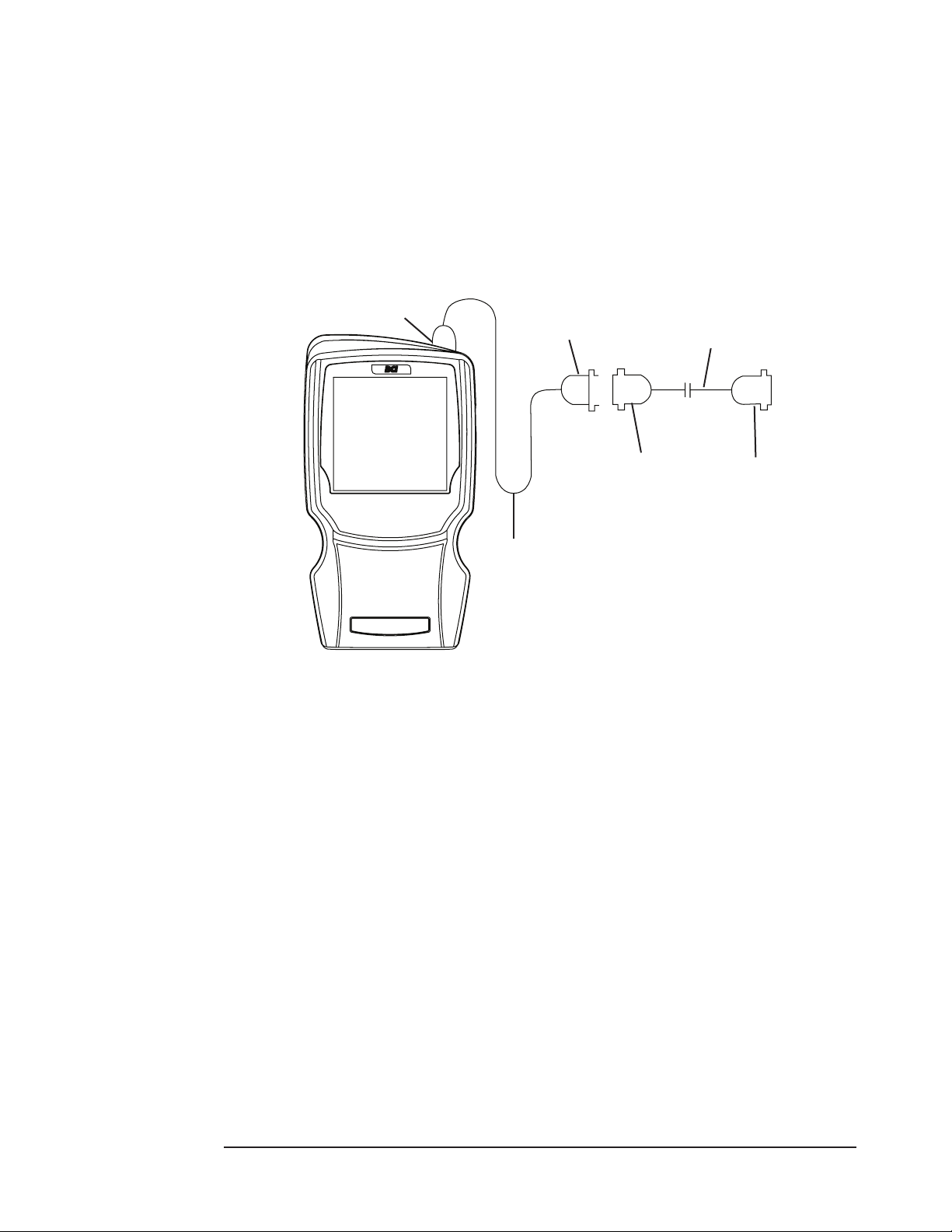
Chapter 7: PC Communication Setup
Sensor / RS232 Port
Trend data may be downloaded in a comma-separated value (.CSV) format to a computer’s serial
(RS232) port.
The following items will be needed:
Oximeter•
HyperTerminal or other PC communication software•
WW3350 Printer Adaptor cable•
3339 PC Adaptor cable•
Connect to Oximeter
Cable ( < WW3350)
Figure 7-3: Connecting to the RS232 Port
How to Set Up Equipment
Refer to Figure 7-3 for the cable connections.
Setup the PC communication program to accept the following RS232 data format:1.
Data Type: ASCII•
Data Format: 9600 baud, 1 start bit, 8 data bits 1 stop bit, no parity•
Select any available RS232 Com Port (typically com1 or com2)•
Turn o the oximeter.2.
Printer Adapter
DB-9 Connector
PC Adapter
DB-9 Connector
Cable ( < 3339)
Connect to IBM
Compatible PC
or Printer
Remove the oximetry sensor from the sensor connector.3.
Connect the printer adaptor cable (WW3350) to the sensor connector. Make sure the “BCI” 4.
end is connected to the oximeter.
Connect the PC adaptor cable’s DB-9 connector to the mating connector of the printer cable 5.
labeled “Printer”.
Connect the other end of the PC adaptor cable to the PC’s RS232 Com Port selected in step 1.6.
Turn on the oximeter to start sending all of the stored trend data to the PC. 7.
NOTE!
7-4 Clinician’s Operation Manual
Review the PC communication program’s instructions to determine how to
1
save the data to the PC.
Page 55

Output Format
Trend data is transmitted in the format shown in Figure 7-4.
Chapter 7: PC Communication Setup
1
2
3
1
Title
2
Patient Record Number
3
Newest data sample is printed rst. Dashes mean no measurements
TREND DATA
ID:009__________________
hh:mm:ss SpO2 Rate PI
(%) (bpm) (%)
00:55:08 -- --- -00:55:04 95% 83 bpm 1.6%
00:54:56 94% 84 bpm 2.8%
00:54:52 96% 83 bpm 2.6%
00:54:48 96% 84 bpm 3.2%
00:54:44 96% 84 bpm 3.6%
00:54:40 94% 86 bpm 3.2%
00:54:36 96% 86 bpm 3.2%
00:54:32 95% 85 bpm 3.0%
00:54:28 96% 85 bpm 3.0%
00:54:24 95% 81 bpm 5.4%
00:54:00 -- --- --
Figure 7-4: Typical ASCII Trend Data Output
were available at that sample time.
4
4
Trended %SpO2, pulse rate and PI values print every 4 seconds
Clinician’s Operation Manual 7-5
Page 56

Chapter 7: PC Communication Setup
This page is intentionally left blank.
7-6 Clinician’s Operation Manual
Page 57

Chapter 8: Maintenance
Chapter 8: Maintenance
Smiths Medical PM, Inc. products have been designed to operate continuously. However, in order
to ensure a continued high level of performance and safety of operation, routine maintenance
must be performed daily.
The Oximeter Service Manual (< WW1923) also contains the circuit diagrams, parts lists, and
descriptions required for carrying out repairs. The Service Manual is shipped with the monitor.
Routine Maintenance
MAINTENANCE ITEM RECOMMENDED ACTION MAINTENANCE INTERVAL
WW1090 Li-Ion
rechargeable battery pack
Charge the battery by
connecting AC power to the
monitor.
When Low Battery Signal is
observed.
After continuous use under
battery power.
Replace the rechargeable
battery pack.
Monitor Surfaces and
Docking Station /Printer
Cables Clean and/or disinfect
Reusable SpO2 sensor
Clean and/or disinfect As required.
Inspect for signs of damage
or deterioration; replace as
required
Clean and/or disinfect When attaching a new patient.
After approximately 300 charge
cycles.
When attaching a new patient.
Daily.
Clinician’s Operation Manual 8-1
Page 58

Chapter 8: Maintenance
Cleaning and Disinfecting
WARNING! Do not autoclave, ethylene oxide sterilize, or immerse the monitor in liquid.
Clean the surfaces of the monitor with a soft cloth moistened in water or a mild soap solution. If
disinfecting is necessary, wipe the surfaces of the monitor with a 70% isopropyl alcohol solution.
If there is contamination with blood borne pathogens or other potentially infectious materials,
then the use of an approved disinfectant of appropriate spectrum for the suspected organisms is
appropriate. Then wipe the surfaces with a soft, water-moistened cloth.
WARNING! Do not allow water, isopropyl alcohol or any other liquid to enter any of the
openings on the monitor. Unplug the AC power cord from the monitor before
cleaning or disinfecting.
CAUTION! Where the equipment has accidentally gotten wet, it should be wiped dry
externally and allowed to dry thoroughly before use.
CAUTION! Before cleaning or disinfecting the printer, unplug the AC adapter, remove the
batteries and remove the paper.
CAUTION! Do not allow printer paper to become wet. If the printer paper gets wet, remove
the paper immediately. Do not use the printer until the paper is replaced.
CAUTION! Disinfectant chemicals may aect the outer case over prolonged use, however
disinfection must be performed.
NOTE! Use only a soft cotton cloth to clean the monitor’s screen. Do not clean the screen
with tissues, paper towels, or any other paper-based wipe. Paper-based wipes can
scratch the screen.
Storage
Whenever possible, the monitor should be stored inside at room temperature in a dry
environment. If it is necessary to store the monitor for an extended period of time, the unit should
be packed in its original shipping container. Storing the monitor for a long period of time may
degrade the battery capacity. Batteries should be removed from the monitor before storing.
See Chapter 11 for storage specications.
NOTE! The monitor may not meet performance specications when stored or used outside
the temperature and humidity ranges listed in Chapter 11: Specications.
8-2 Clinician’s Operation Manual
Page 59

Chapter 9: Troubleshooting
Chapter 9: Troubleshooting
WARNING! If the accuracy of any measurement is in question, check the patient’s vital signs
by an alternative method, and then check the monitor for proper functioning.
Power
PROBLEM POSSIBLE CAUSE CORRECTIVE ACTION
The oximeter doesn’t
turn on.
Batteries weak and/ or no AC
power.
Replace or recharge the batteries.
Connect to source of AC power.
The oximeter turns
on, but display
reads:
L0
Bat
The oximeter turns
o unexpectedly.
The External Power
indicator X is not
lit (AC Power).
The External Power
indicator X is not
lit (USB Cable).
The USB Power
indicator is not
lit. (Docking Station)
The monitor
operates on AC
power, but not on
battery power.
Batteries not installed or
batteries incorrectly installed.
AC power is connected, but no
or weak batteries are installed.
Batteries are weak or dead
and no AC power source is
connected.
An External AC Power Supply
cord is not connected to the
monitor or accessory cable.
The accessory cable is not
connected to the monitor.
The AC power cord is connected
to a wall outlet that is controlled
by a wall switch.
A non user-serviceable fuse may
have opened.
The USB cable is not connected
to a source of power or the USB
power source is not operating.
AC Power is connected.
The USB cable is not connected
to a source of power or the USB
power source is not operating.
The battery is missing.
The battery is drained.
Ensure the batteries are installed
correctly.
Connect to source of AC power.
This is proper operation.
Replace or recharge the batteries.
Replace or recharge the batteries.
Connect to source of AC power.
Check all power supplies and cables
for proper connections.
Only connect the AC power cord to an
outlet that is not controlled by a wall
switch.
Contact your authorized service
representative.
Check all cable connections and
conrm PC, USB hub or other source
of USB power is working correctly.
This is proper operation.
Check all cable connections and
conrm PC, USB hub or other source
of USB power is working correctly.
Replace the battery.
Charge or replace the battery.
Replace the battery
The battery is defective.
Clinician’s Operation Manual 9-1
Contact your authorized service
representative if using LI-Ion
rechargeable battery pack.
Page 60

Chapter 9: Troubleshooting
PROBLEM POSSIBLE CAUSE CORRECTIVE ACTION
The monitor displays
27
when
ERR
powered up.
Battery run time is
excessively short
on a fully charged
battery.
The battery is defective. Disconnect the AC power cord and
then reconnect it. If the error message
persists, the battery is defective.
Contact your authorized service
representative.
The LI-Ion rechargeable battery
pack must be replaced.
Contact your authorized service
representative.
Sensor
PROBLEM POSSIBLE CAUSE CORRECTIVE ACTION
No pulse shown on
the bargraph or PI
graph.
Patient cable or sensor is
disconnected from the oximeter.
Sensor is incorrectly positioned
on the patient.
Check sensor connections to the
patient cable and to the oximeter.
Reposition the sensor.
The pulse rate is
erratic, intermittent,
or incorrect.
SpO2 value is erratic,
intermittent, or
incorrect.
Poor patient perfusion.
Defective sensor or patient
cable.
The SpO
positioned on the patient.
The patient is experiencing poor
perfusion.
The patient is moving too much.
There is too much ambient light
around the SpO2 sensor.
Defective sensor or patient
cable.
Poor patient perfusion.
Patient motion.
sensor is improperly
2
Reposition the sensor.
Try a new sensor or contact your
authorized service representative for
help.
Reposition the sensor on the patient.
Conrm signal level with PI and signal
bar graphs.Reposition the sensor on
the patient.
Make sure that the patient remains
still. Place the extremity on a pillow
that acts as a buer to motion.
Shield the SpO2 sensor with a towel.
Try a new sensor or contact your
authorized service representative for
help.
Conrm signal level with PI and signal
bar graphs.
Reposition the sensor on the patient.
Patient must remain still to obtain an
accurate measurement.
Defective sensor or patient
cable.
9-2 Clinician’s Operation Manual
Try a new sensor or contact your
authorized service representative for
help.
Page 61

Chapter 9: Troubleshooting
Other
PROBLEM POSSIBLE CAUSE CORRECTIVE ACTION
No printout on
optional printer.
AC power is not connected to
the Docking Station.
Connect AC Power to the Docking
Station.
“?” malfunction
indicator on the
printer is lit.
Real time or
trend data is not
transmitted.
Display shows
RA
ERR
Display shows
sr
ERR
Display shows
24
ERR
Display shows
25
ERR
Display shows
ERR
No trends in memory.
No paper or paper incorrectly
loaded.
Printer interface malfunction.
Printer door open.
Printer out of paper.
An accessory cable is defective.
Oximeter is not properly seated
in Docking Station.
The communications setup is
not correct.
Remote alarm cable attached to
the oximeter.
No sensor attached to the
oximeter.
Defective sensor or patient
cable.
EEPROM checksum Error Contact your authorized service
Trend Checksum Error Contact your authorized service
Internal oximetry failure. Contact your authorized service
Take trend data.
See Chapter 6: Optional Docking
Station and Printer for details of
loading paper.
Contact your authorized service
representative for help.
Close the printer door.
Install a roll of printer paper.
Contact your authorized service
representative.
Remove the oximeter from the
Docking Station and replace it
assuring proper alignment.
Check the user-connected auxiliary
equipment and software.
This is proper operation. The WW1020
and WW1000 are not intended for use
with the remote alarm cable.
Attach a sensor to the oximeter.
Try a new sensor. If the problem
persists, contact your authorized
service representative.
representative.
representative.
representative.
Clinician’s Operation Manual 9-3
Page 62

Chapter 9: Troubleshooting
This page is intentionally left blank.
9-4 Clinician’s Operation Manual
Page 63

Chapter 10: Optional Supplies and Accessories
Chapter 10: Optional Supplies and Accessories
CAT. NO. DESCRIPTION Q T Y.
WW1000
WW1018R
WW1018Y
WW1018G
WW1018B
WW1020 Pulse Oximeter (with Serial Autocorrelation) each
WW1025
WW1026
WW1027 Thermal Printer Paper 5/pk
WW1080 Replacement Sensor Cradles (3) set
WW1081 Rubber Feet for Mounting Bracket - Replacement pair
WW1089
WW1090 Rechargeable battery pack, LI-Ion each
WW1095 Universal AC mains adapter - 30W each
WW1098 Universal Mounting Bracket each
WW1101 Mounting Bracket Strap - Replacement each
1300 Sensor, Oximetry, Disposable, Adult Finger 10/box
1301 Sensor, Oximetry, Disposable, Pediatric. Finger, 15-45 kg 10/box
1302 Sensor, Oximetry, Disposable, Neonate/Small Infant, < 3 kg* 10/box
1303 Sensor, Oximetry, Disposable, Infant, 3-15 kg 10/box
1606 Simulator, Oximeter each
WW1922 Manual, Operation each
WW1923 Manual, Service each
3025 Sensor, Oximetry, Wrap, Infant, 3-15 kg each
3026 Sensor, Oximetry, Wrap, Neonate/Small Infant, < 3 kg* each
3043 Sensor, Oximetry, Universal ‘Y’ each
3044 Sensor, Oximetry, Finger each
3044S Spot Check Sensor, Reusable, Adult each
3049 Microfoam Strips, Adhesive for use with 3025, 3026 and 3043 40/pkg
WW3078 Sensor, Oximetry, Ear each
3134 Tape, Attachment, Neonatal/Small Infant 50/pkg
3135 Tape, Attachment, Infant 50/pkg
3136 Tape, Attachment, Neonatal/Small Infant 100/pkg
3137 Tape, Attachment, Infant 100/pkg
3138 Posey Wrap, Attachment, Universal ‘Y’ for use with 3025, 3026 and 3043 10/pkg
3178 Sensor, Pediatric Finger, 5-45 kg each
3178S Spot Check Sensor, Reusable, Pediatric each
3311 Cable, Oximetry, 1.5 m (5 feet) each
* The BCI® 1302 and 3026 oximetry sensors should not be used on neonatal patients with the WW1000
monitor. Testing has not been conducted for the WW1000 for patients less than 30 days old. These sensors
may, however be used on older patients.
Pulse Oximeter
Protective glove - red
Protective glove - yellow
Protective glove - green
Protective glove - blue
Docking Station
Printer (Must be used with Docking Station WW1025)
USB interface cable
each
each
each
each
each
each
each
each
Clinician’s Operation Manual 10-1
Page 64

Chapter 10: Optional Supplies and Accessories
CAT. NO. DESCRIPTION Q T Y.
3339 PC adapter cable each
WW3350 Printer adapter cable each
3444 Sensor, Oximetry, Finger, Comfort Clip® each
Ordering Information
Outside the USA, for ordering information, contact your local distributor. In the USA, for ordering
information, contact the customer service department at the address or phone number below:
Smiths Medical PM, Inc.
N7W22025 Johnson Drive
Waukesha, WI 53186 USA
web site: www.smiths-medical.com
E-mail address: [email protected]
Phone: (262) 542-3100
Toll-Free: (800) 558-2345 (USA only)
Fax: (262) 542-0718
10-2 Clinician’s Operation Manual
Page 65

Chapter 11: Specications
Displays
Chapter 11: Specications
SpO2:
Pulse Rate: 3-digit LED display, 12.7 mm high.
PI: 9-segment LED bar graph.
Pulse Signal Strength: Logarithmically scaled 9-segment LED bar graph.
Display update rate
SpO2 and Pulse rate: 2Hz
All other data: 10Hz
Display Refresh: 50 Hz
2-digit LED display, 19 mm high.
Indicators
Visual
External Power indicator:
Battery charge indicator: ( green/yellow) with 4 segment gauge; green if 2-4 segments
(
green) with power plug icon.
lit, yellow if only one segment is lit.
Keys/User Controls
On/O Key ( •
x
)
Clinician’s Operation Manual 11-1
Page 66

Chapter 11: Specications
SpO2 for the WW1020 Oximeter
SpO2 Range:
SpO2 Resolution: 1 count (%SpO2)
SpO2 Averaging:
Calibration:
Sensors: Red: 660 nm, 2 mW (typical)
SpO2 Accuracy: 70 to 100% SpO2, less than 70% SpO2 is undened.
0-100% Functional Saturation (Display Maximum: 99%)
8 beats
Factory calibrated over range 70% to 100% SpO2 using human blood
samples to functional saturation. Test methods are available upon request.
No in-service calibration is required.
Infrared: 905 nm, 2-2.4 mW (typical)
SpO2 Accuracy in
Sensor
BCI® 1300
BCI® 1301
BCI® 1302
BCI® 1303
BCI® 3025
BCI® 3026
BCI® 3043
BCI® 3044
BCI® 3044S
BCI® 3078
BCI® 3178
BCI® 3178S
BCI® 3444
Nellcorr® DS100A
1
Because pulse oximeter measurements are statistically distributed, only about two-thirds of pulse
Normal Conditions
±2 A
RMS
4
A
±2
14
A
±3
±2 5 A
±2.5 6 A
±3.5 14 A
±3 A
RMS
±2 A
RMS
±2 7 A
±3.6 A
±2 A
RMS
±2 8 A
±2 A
RMS
±2.5 A
1, 2
RMS
RMS
RMS
RMS
RMS
RMS
RMS
RMS
RMS
oximeter equipment measurements can be expected to fall within the ± A
SpO2 Accuracy in
Low Perfusion Conditions
±2 9 A
RMS
±2 9 A
RMS
±3 14 A
RMS
±2 9 A
RMS
±2.5 10 A
±3.5 14 A
±3 A
±2 A
±2 11 A
±3.6 A
±2 A
±2 12 A
±2 A
±2.5 A
RMS
RMS
RMS
RMS
RMS
RMS
RMS
RMS
RMS
RMS
1, 3
Motion Conditions
±3 A
±3 13 A
unspecied
unspecied
unspecied
unspecied
unspecied
unspecied
unspecied
unspecied
unspecied
unspecied
unspecied
unspecied
of the value measured by
RMS
SpO2 Accuracy in
15
RMS
RMS
the CO-oximeter.
2
The WW1020 has been validated on 10 adult volunteers that did not have health problems and were
non-smokers. The study was conducted at oxygen concentrations evenly distributed over an SpO2 range
of 70-100%.
3
Pulse Amplitude 1% to 0.1%. Tested using industry standard simulator.
4
Clinical accuracy based on BCI® 1300; 5 Clinical accuracy based on BCI® 1302.
6
Clinical accuracy based on BCI® 3026; 7 Clinical accuracy based on BCI® 3044.
8
Clinical accuracy based on BCI® 3178; 9 Clinical accuracy based on BCI® 1302.
10
Clinical accuracy based on BCI® 3026;
12
Clinical accuracy based on BCI® 3178;
14
For neonatal patients, 1%-SpO2 was added to account for theoretical dierences in pulse oximetry
11
Clinical accuracy based on BCI® 3044.
13
Clinical accuracy based on BCI® 1300.
function between adult and neonatal hemoglobin. This investigation was performed on adults only.
15
Motion patterns used consisted of tapping and rubbing. Subjects varied the motion frequencies to a
maximum of 300 cycles per minute. A maximum amplitude of approximately 2.5 cm was used in this
study.
11-2 Clinician’s Operation Manual
Page 67

Pulse Rate for the WW1020 Oximeter
Pulse Rate Range: 20-300 bpm
Pulse Rate Resolution: 1 BPM
Pulse Rate Averaging: 8 seconds
Pulse Rate Accuracy:
Chapter 11: Specications
Sensor
BCI® 1300
BCI® 1301
BCI® 1302
BCI® 1303
BCI® 3025
BCI® 3026
BCI® 3043
BCI® 3044
BCI® 3044S
BCI® 3078
BCI® 3178
BCI® 3178S
BCI® 3444
Nellcorr®
Pulse Rate Accuracy
in Normal Conditions
20-300bpm
±2 A
RMS
±2 A
RMS
±2 A
RMS
±2 A
RMS
±2 A
RMS
±2 A
RMS
±2 A
RMS
±2 A
RMS
±2 A
RMS
±2 A
RMS
±2 A
RMS
±2 A
RMS
±2 A
RMS
±2 A
RMS
Pulse Rate Accuracy in
1
Low Perfusion Conditions
25-250bpm
±3 3 A
RMS
±3 3 A
RMS
±3 A
RMS
±3 3 A
RMS
±3 4 A
RMS
±3 A
RMS
±3 A
RMS
±3 A
RMS
±3 5 A
RMS
±3 6 A
RMS
±3 A
RMS
±3 7 A
RMS
±3 A
RMS
±3 A
RMS
DS100A
1
Pulse Amplitude 6%. Tested using industry standard simulator.
2
Pulse Amplitude 1% to 0.1%. Tested using industry standard simulator.
3
Low Perfusion simulator accuracy specication based on BCI® 1302.
4
Low Perfusion simulator accuracy specication based on BCI® 3026.
5
Low Perfusion simulator accuracy specication based on BCI® 3044.
6
Pulse Amplitude 1% to 0.3%. Tested using industry standard simulator.
7
Low Perfusion simulator accuracy and specication based on BCI® 3178.
Pulse Rate Accuracy
2
in Motion Conditions
20-300bpm
unspecied
unspecied
unspecied
unspecied
unspecied
unspecied
unspecied
unspecied
unspecied
unspecied
unspecied
unspecied
unspecied
unspecied
Clinician’s Operation Manual 11-3
Page 68

Chapter 11: Specications
SpO2 for the WW1000 Oximeter
SpO2 Range: 0-99% Functional Saturation
SpO2 Resolution: 1 count (%SpO2)
SpO2 Averaging: 8 beats
Calibration: Factory calibrated over range 70% to 99% SpO2 using human blood samples
to functional saturation. Test methods are available upon request. No inservice calibration is required.
Sensors: Red: 660 nm, 2 mW (typical)
Infrared: 905 nm, 2-2.4 mW (typical)
SpO2 Accuracy: 70 to 99% SpO2, less than 70% SpO2 is undened.
BCI® Sensor
1300
1301
1302
1303
3025
3026
3043
3044
3044S
3078
3178
3178S
3444
1
Because pulse oximeter measurements are statistically distributed, only about two-thirds of pulse
in Normal Conditions
±2 A
RMS
±2 4 A
RMS
±2 4 A
RMS
±2 4 A
RMS
±2.5 5 A
±2.5 A
RMS
±3 A
RMS
±2 A
RMS
±2 6 A
RMS
±3 A
RMS
±2 A
RMS
±2 7 A
RMS
±2 A
RMS
SpO2 Accuracy
RMS
1, 2
in Low Perfusion Conditions
oximeter equipment measurements can be expected to fall within the ± A
SpO2 Accuracy
±2 8 A
RMS
±2 8 A
RMS
±2 A
RMS
±2 8 A
RMS
±2.5 9 A
±2.5 A
±3 A
±2 A
±2 10 A
±3 11 A
±2 A
±2 12 A
±2 A
of the value measured by
RMS
RMS
RMS
RMS
RMS
RMS
RMS
RMS
RMS
RMS
1, 3
the CO-oximeter.
2
The WW1000 has been validated on 10 adult volunteers that did not have health problems and were
non-smokers. The study was conducted at oxygen concentrations evenly distributed over an SpO2 range
of 70-100%.
3
Pulse Amplitude 1% to 0.1%. Tested using industry standard simulator.
4
Clinical accuracy based on BCI® 1300.
5
Clinical accuracy based on BCI® 3026.
6
Clinical accuracy based on BCI® 3044.
7
Clinical accuracy based on BCI® 3178.
8
Low Perfusion simulator accuracy and specication based on BCI® 1302.
9
Low Perfusion simulator accuracy and specication based on BCI® 3026.
10
Low Perfusion simulator accuracy and specication based on BCI® 3044.
11
Pulse Amplitude 1% to 0.3%. Tested using industry standard simulator.
12
Low Perfusion simulator accuracy and specication based on BCI® 3178.
11-4 Clinician’s Operation Manual
Page 69

Pulse Rate for the WW1000 Oximeter
Pulse Rate Range: 30-254 bpm
Pulse Rate Resolution: 1 bpm
Pulse Rate Averaging: 8 seconds
Pulse Rate Accuracy:
Chapter 11: Specications
BCI® Sensor
Pulse Rate Accuracy
in Normal Conditions
1
in Low Perfusion Conditions
30-254bpm
1300
1301
1302
1303
3025
3026
3043
3044
3044S
3078
3178
3178S
3444
1
Pulse Amplitude 6%. Tested using industry standard simulator.
2
Pulse Amplitude 1% to 0.1%. Tested using industry standard simulator.
3
Low Perfusion simulator accuracy specication based on BCI® 1302.
4
Low Perfusion simulator accuracy specication based on BCI® 3026.
5
Low Perfusion simulator accuracy specication based on BCI® 3044.
6
Pulse Amplitude 1% to 0.3%. Tested using industry standard simulator.
7
Low Perfusion simulator accuracy and specication based on BCI® 3178.
±2 A
±2 A
±2 A
±2 A
±2 A
±2 A
±2 A
±2 A
±2 A
±2 A
±2 A
±2 A
±2 A
RMS
RMS
RMS
RMS
RMS
RMS
RMS
RMS
RMS
RMS
RMS
RMS
RMS
Pulse Rate Accuracy
30-250bpm
±3 3 A
RMS
±3 3 A
RMS
±3 A
RMS
±3 3 A
RMS
±3 4 A
RMS
±3 A
RMS
±3 A
RMS
±3 A
RMS
±3 5 A
RMS
±3 6 A
RMS
±3 A
RMS
±3 7 A
RMS
±3 A
RMS
2
Clinician’s Operation Manual 11-5
Page 70

Chapter 11: Specications
Pulse Amplitude Index for the WW1020 Oximeter
Range: 0.03% to 20.00% 6 (0.01% increments)
Pulse Amplitude Index is dened as PI = (100 * AC)/DC where AC is
the alternating current (pulsatile component of the signal) and DC is
direct current (non-pulsatile component of the signal). It is a relative
measure of pulse-signal strength over time at a pulse oximeter
monitoring site, and is non-pulsatile in nature.
Display: 9-segment green / yellow LED bargraph, logarithmic scale
Display Update Rate: 10 Hz
The oximeter will display dashes (Invalid data) for SpO2 and PR when the PI value is below 0.03%.
Low perfusion performance is veried by simulator testing.
6
As tested with Industry Standard Simulator.
The PI value maps to a 9-segment bar graph as shown below. The two lowest bars (1&2) are bicolor (Yellow & Green), and bars 3 through 9 are Green.
PI From
Oximeter
Segments
Lit
0.00-
0.07
1Y 2Y 3G 4G 5G 6G 7G 8G 9G
0.08-
0.15
0.16-
0.31
0.32-
0.63
0.64-
1.27
1.28-
2.55
2.56-
5.11
5.12-
10.23
10.24-
20.47
Pulse Amplitude Index for the WW1000 Oximeter
Range: 0.00% to 20.00% 5 (0.2% increments)
Pulse Amplitude Index is dened as PI = (100 * AC)/DC where AC
is the alternating current (pulsatile component of the signal) and
DC is direct current (non-pulsatile component of the signal). It is
a relative measure of pulse-signal strength over time at a pulse
oximeter monitoring site, and is non-pulsatile in nature.
Display: 9-segment green / yellow LED bargraph, logarithmic scale
Display Update Rate: 10 Hz
5
As tested with Industry Standard Simulator.
The PI value maps to a 9-segment bar graph as shown below. The two lowest bars (1&2) are bicolor (Yellow & Green), and bars 3 through 9 are Green.
PI From
Oximeter
Segments
Lit
0.00 >0 - 0.2
1Y 2Y 3G 4G 5G 6G 7G 8G 9G
>0.2
- 0.4
>0.4
- 0.6
>0.6
- 1.2
>1.2
- 2.6
>2.6
- 5.0
>5.0
- 10.2
>10.2
Printer
Paper: 58mm (2.28 inches), Thermal
Modes: Real Time, Tabular Trend, Graphic Trend
Paper Speed: 12.5 mm/sec
Trend Graphs: Headers print with graphs
11-6 Clinician’s Operation Manual
Page 71

Chapter 11: Specications
Serial Data Output
Power Input and Data Connector
Data transferred through this connector is in a proprietary BCICP1030 format. Format available
upon request.
Sensor Connector
Data Type: ASCII comma delimited string output at 1 Hz. Lines terminated with a
carriage return.
Serial Data Protocol: RS232C, 9600 baud, 1 start bit, 8 data bits, 1 stop bit, no parity.
Power Requirements
Battery
Type:
AA (LR6) disposable:
Custom rechargeable:
Use Time:
AA (LR6) disposable:
Custom rechargeable:
Charge Time:
AA (LR6) disposable:
Custom rechargeable:
Charge Cycles:
(Custom rechargeable)
4 Alkaline
Lithium-Ion (L+), 7.4V replaceable rechargeable battery pack.
WW1020 - Approximately 26 hours continuous use
WW1000 - Approximately 32 hours continuous use
WW1020 - Approximately 31 hours continuous use (new)
WW1000 - Approximately 54 hours continuous use (new)
Not rechargeable.
Fast charges in approximately 3 hours. Charge time aected by input
power source and device loading. See Chapter 4: Operating Instructions.
300 to 80% capacity
AC Charger
WW1095 30 Watt AC Power Supply: 9V, 3A output, Input of 100-240 VAC 50Hz, 60Hz.
USB
WW1089 USB Interface Cable: Input: 5V, 500mA max (USB powered source )
Output: 9V, 230mA max to oximeter.
Length: Maximum 5 meters (16.4 feet)
Monitor Dimensions
Width: 85 mm (3.3 inches)
Height: 154 mm (6.1 inches)
Depth: 45 mm (1.7 inches)
Weight: 340 grams (12 ounces) with four (4) AA batteries
369 grams (13 ounces) with rechargeable battery pack
Clinician’s Operation Manual 11-7
Page 72

Chapter 11: Specications
Dock Dimensions
DIMENSION WITHOUT PRINTER WITH PRINTER
Width: 107 mm (4.2 inches) 160 mm (6.3 inches)
Height: 84 mm (3.3 inches) 84 mm (3.3 inches)
Depth: 109 mm (4.3 inches) 109 mm (4.3 inches)
Weight: 570 grams (20 ounces) 850 grams (30 ounces)
Auxiliary Inputs/Outputs
Sensor: DB9
Data or
Power Input
Connector: Non-standard 16 pin docking connector for power and data.
Environmental
Operating Temperature
Oximeter and accessories: 0°C to 55°C (32°F to 131°F)
Printer: 0°C to 50°C (32°F to 122°F)
Power Supply: 0°C to 40°C (32°F to 104°F)
Li+ battery charging: 5°C to 45°C (41°F to 113°F)
Operating Humidity
Oximeter and accessories: 15 to 95% (non-condensing)
Printer: 20 to 85% (non-condensing)
Power Supply: 5 to 95% (non-condensing)
Storage Temperature
Oximeter and accessories: -40°C to +75°C (-40°F to +167°F)
WW1090 LI-Ion rechargeable
battery pack: -20°C to +60°C (-4°F to 140°F)
Printer: -25°C to +70°C (-13°F to +158°F)
Power Supply: -10°C to +70°C (14°F to 158°F)
Storage Humidity
Oximeter and accessories: 10 to 95% (non-condensing)
Printer: 10 to 90% (non-condensing)
Power Supply: 5 to 95% (non-condensing)
Altitude: 3050 m (10,000 ft) max
Shock and vibration: ISO 9919 transport rated
NOTE! The monitor may not meet performance specications when stored or used outside
the temperature and humidity ranges listed above.
11-8 Clinician’s Operation Manual
Page 73

Chapter 11: Specications
Equipment Classication
Type of Protection Against Electric
shock: Class II or Internally Powered
Mode of operation: Spot Check (non-continuous)
Degree of Protection Against ingress
of Liquids: IPX2, drip proof
Degree of Mobility: Portable
Degree of Protection Against Electric
Shock: Type BF
Electromagnetic classication: CISPR 11 Group1, Class B, see Appendix A: Guidance and
Manufacturer’s Declaration.
Design Standards
Safety: EN60601-1 / IEC 60601-1
EMC: EN60601-1-2 / IEC 60601-1-2
SpO
:
2
FDA Draft Guidance for Pulse Oximeters, July 2007
ISO 9919 / EN ISO 9919
Clinician’s Operation Manual 11-9
Page 74

Chapter 11: Specications
This page is intentionally left blank.
11-10 Clinician’s Operation Manual
Page 75

Appendix A: Guidance and Manufacturer’s Declaration
Appendix A: Guidance and Manufacturer’s Declaration
Guidance and Manufacturer’s Declaration
The WW1020/WW1000 pulse oximeter is intended for use in the electromagnetic environment
specied in the tables within this appendix.
NOTE! The WW1020/WW1000 pulse oximeter system must be put into service according to
the provided EMC information to ensure proper operation.
Electromagnetic Emissions - Emissions Test
GUIDANCE AND MANUFACTURER’S DECLARATION ELECTROMAGNETIC EMISSIONS
The WW1020/WW1000 pulse oximeter is intended for use in the electromagnetic environment
specied below. The customer or end user of the WW1020/WW1000 pulse oximeter should
ensure that it is used in such an environment.
ELECTROMAGNETIC ENVIRONMENT
EMISSIONS TEST COMPLIANCE
RF emissions
CISPR 11
RF emissions
CISPR 11
Harmonic emissions IEC
61000-3-2
Voltage uctuations/
icker emissions
IEC 61000-3-3
Group 1 The WW1020/WW1000 pulse oximeter uses
Class B The WW1020/WW1000 pulse oximeter
Class A
Complies
RF energy only for its internal function.
Therefore, its RF emissions are very low and
are not likely to cause any interference in
nearby electronic equipment.
is suitable for use in all establishments,
including domestic establishments and those
directly connected to the public low-voltage
power supply network that supplies buildings
used for domestic purposes.
GUIDANCE
Clinician’s Operation Manual A-1
Page 76

Appendix A: Guidance and Manufacturer’s Declaration
Electromagnetic Immunity - Immunity Test
GUIDANCE AND MANUFACTURER’S DECLARATION ELECTROMAGNETIC IMMUNITY
The WW1020/WW1000 pulse oximeter is intended for use in the electromagnetic environment
specied below. The customer or end user of the WW1020/WW1000 pulse oximeter should
ensure that it is used in such an environment.
ELECTROMAGNETIC
IMMUNITY TEST IEC 60601 TEST LEVEL
Electrostatic
discharge (ESD)
IEC 61000-4-2
Electrical fast
transient/burst
IEC 61000-4-4
Surge
IEC 61000-4-5
Voltage dips, short
interruptions, and
voltage variations
on power supply
input lines
IEC 61000-4-11
Power frequency
(50/60 Hz)
magnetic eld
IEC 61000-4-8
±6 kV contact
±8 kV air
±2 kV for power supply
lines.
±1 kV for input/output
lines
±1 kV dierential mode
±2 kV common mode
<5% UT
(>95% dip in UT)
for 0.5 cycle
<40% UT
(>60% dip in UT)
for 5 cycles
<70% UT
(>30% dip in UT)
for 25 cycles
<5% UT
(>95% dip in UT)
for 5 sec
3 A/m 3 A/m Power frequency magnetic
COMPLIANCE
LEVEL
±6 kV contact
±8 kV air
±2 kV for power
supply lines.
±1 kV for input/
output lines
±1 kV dierential
mode
±2 kV common
mode
<5% UT
(>95% dip in UT)
for 0.5 cycle
<40% UT
(>60% dip in UT)
for 5 cycles
<70% UT
(>30% dip in UT)
for 25 cycles
<5% UT
(>95% dip in UT)
for 5 sec
ENVIRONMENT
GUIDANCE
Floors should be wood,
concrete or ceramic tile.
If oors are covered with
synthetic material, the
relative humidity should be
at least 30%.
Mains power quality should
be that of typical commercial
or hospital environment.
Mains power quality should
be that of typical commercial
or hospital environment.
Mains power quality
should be that of typical
commercial or hospital
environment. If the user
of the WW1020/WW1000
pulse oximeter requires
continued operation during
power mains interruptions,
it is recommended that the
WW1020/WW1000 pulse
oximeter be powered from
an uninterruptible power
supply or a battery.
elds should be at levels
characteristic of a typical
commercial or hospital
environment.
Note: UT is the a.c. mains voltage prior to application of the test level.
A-2 Clinician’s Operation Manual
Page 77

Appendix A: Guidance and Manufacturer’s Declaration
GUIDANCE AND MANUFACTURER’S DECLARATION ELECTROMAGNETIC IMMUNITY
The WW1020/WW1000 pulse oximeter is intended for use in the electromagnetic environment
specied below. The customer or end user of the WW1020/WW1000 pulse oximeter should
ensure that it is used in such an environment.
IMMUNITY TEST
IEC 60601 TEST
LEVEL
COMPLIANCE
LEVEL
ELECTROMAGNETIC
ENVIRONMENT GUIDANCE
Portable and mobile RF
communication equipment should
be used no closer to any part
of the WW1020/WW1000 pulse
oximeter, including cable, than the
recommended separation distance
calculated from the equation
applicable to the frequency of the
transmitter.
Conducted RF
IEC 61000-4-6
Radiated RF
IEC 61000-4-3
3 Vrms
150 kHz to 80
MHz
3 V/m
80 MHz to 2.5 GHz
2 Hz Modulation
20 V/m
80 MHz to 2.5 GHz
1kHz Modulation
3 Vrms
3 V/m
20 V/m
Recommended separation distance:
d = 1.2√P
d=1.2√P 80 MHz to 800 MHz
d=2.3√P 800 MHz to 2.5 GHz
d = 0.18√P 80 MHz to 800 MHz
d = 0.35√P 800 MHz to 2.5 GHz
where P is the maximum output
power rating of the transmitter
in watts (W) according to the
transmitter manufacturer and d
is the recommended separation
distance in meters (m).
Field strengths from xed RF
transmitters, as determined by
an electromagnetic site survey,a
should be less than the compliance
level in each frequency range.
Interference may occur in the
vicinity of equipment marked with
the following symbol:
b
4
Note 1 At 80 MHz and 800 MHz, the higher frequency range applies.
Note 2 These guidelines may not apply in all situations. Electromagnetic propagation is aected by
absorption and reection from structures, objects and people.
a
Field strengths from xed RF transmitters, such as base stations for radio (cellular/cordless) telephones
and land mobile radios, amateur radio, AM and FM radio broadcast and TV broadcast cannot be predicted
theoretically with accuracy. To assess the electromagnetic environment due to xed RF transmitters, an
electromagnetic site survey should be considered. If the measured eld strength in the location in which
the WW1020/WW1000 pulse oximeter is used exceeds the applicable RF transmitter compliance level
above, the WW1020/WW1000 pulse oximeter should be observed to verify normal operation. If abnormal
performance is observed, additional measures may be necessary, such as reorienting or relocating the
WW1020/WW1000 pulse oximeter.
b
Over the frequency range 150 kHz to 80 MHz, eld strengths should be less than 3 V/m.
Clinician’s Operation Manual A-3
Page 78
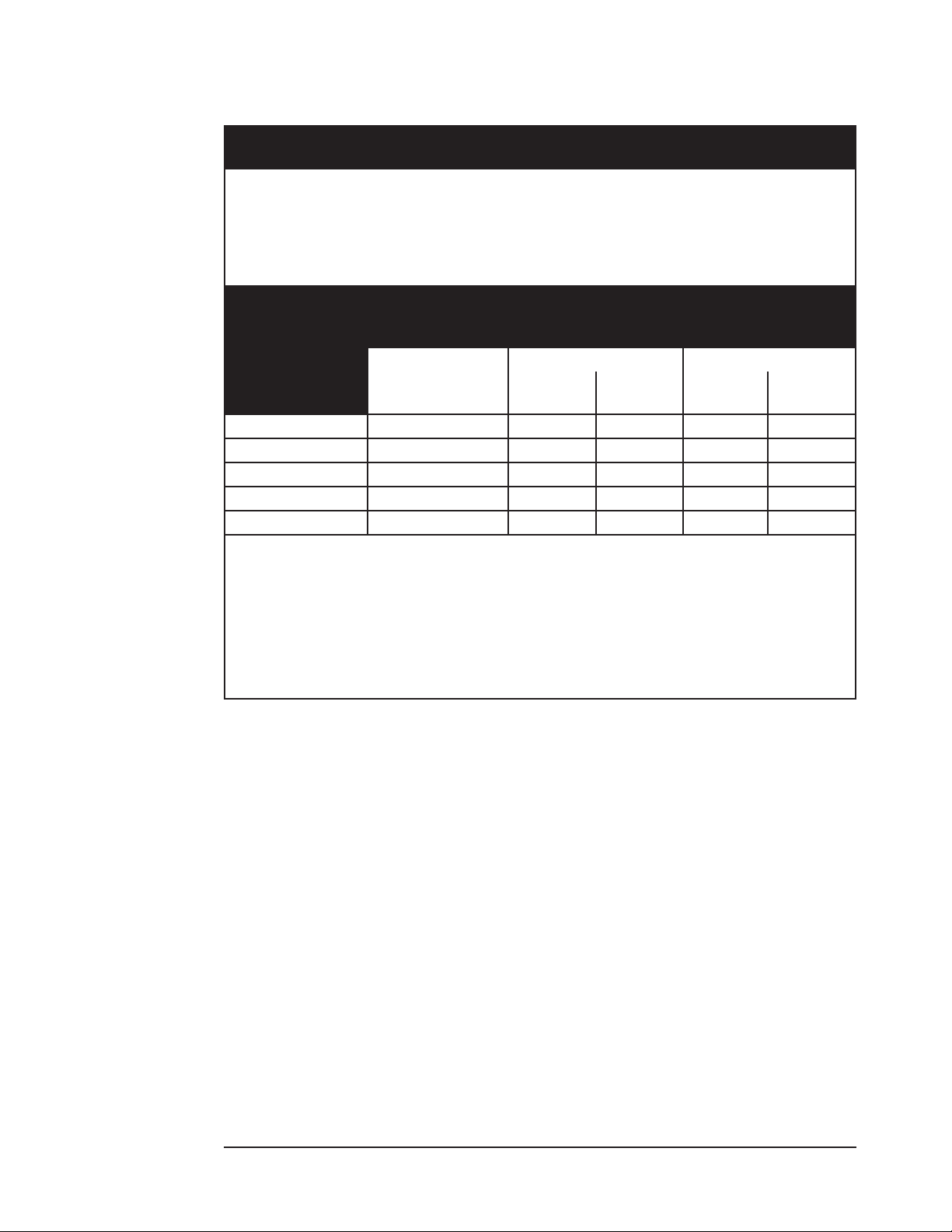
Appendix A: Guidance and Manufacturer’s Declaration
Recommended Separation Distances
RECOMMENDED SEPARATION DISTANCE BETWEEN PORTABLE AND MOBILE
RF COMMUNICATIONS EQUIPMENT AND THE WW1020/WW1000 PULSE OXIMETER
The WW1020/WW1000 pulse oximeter is intended for use in the electromagnetic environment
in which radiated RF disturbances are controlled. The customer or the user of the WW1020/
WW1000 pulse oximeter can help prevent electromagnetic interference by maintaining a
minimum distance between portable and mobile RF communications equipment (transmitters)
and the WW1020/WW1000 pulse oximeter as recommended below, according to the maximum
output power of the communication equipment.
SEPARATION DISTANCE ACCORDING TO
RATED MAXIMUM
OUTPUT POWER
OF TRANSMITTER
W
0.01 .12 0.12 0.02 0.23 0.04
0.1 .38 0.38 0.06 0.73 0.11
1 1.2 1.20 0.18 2.30 0.35
10 3.8 3.79 0.57 7.27 1.11
100 12 12.00 1.80 23.00 3.50
For transmitters rated at a maximum output power not listed above, the recommended
separation distance d in meters (m) can be estimated using the equation applicable to the
frequency of the transmitter, where P is the maximum output power rating of the transmitter in
watts (W) according to the transmitter manufacturer.
150 kHz to 80 MHz
d = 1.2√P
FREQUENCY OF TRANSMITTER
m
80 MHz to 800 MHz 800 MHz to 2.5 GHz
3 V/m
d=1.2√P
20 V/m
d = 0.18√P
3 V/m
d=2.3√P
20 V/m
d = 0.35√P
Note 1 At 80 MHz and 800 MHz, the higher frequency range applies.
Note 2 These guidelines may not apply in all situations. Electromagnetic propagation is aected
by absorption and reection from structures, objects and people.
A-4 Clinician’s Operation Manual
Page 79

Appendix A: Guidance and Manufacturer’s Declaration
The following is a list of cables, transducers and accessories used with the WW1020/WW1000
pulse oximeter.
WARNING! Use of accessories, transducers and cables other than those specied below
may result in increased emissions or decreased immunity of the systems.
BCI® Accessories
CAT. NO. DESCRIPTION
WW1025
WW1026
WW1089
WW1090 Rechargeable battery pack, LI-Ion
WW1095 Universal AC mains adapter - 30W
1300 Sensor, Oximetry, Disposable, Adult Finger
1301 Sensor, Oximetry, Disposable, Pediatric. Finger, 15-45 kg
1302 Sensor, Oximetry, Disposable, Neonate/Small Infant, < 3 kg*
1303 Sensor, Oximetry, Disposable, Infant, 3-15 kg
3025 Sensor, Oximetry, Wrap, Infant, 3-15 kg
3026 Sensor, Oximetry, Wrap, Neonate/Small Infant, < 3 kg*
3043 Sensor, Oximetry, Universal ‘Y’
3044 Sensor, Oximetry, Finger
3044S Spot Check Sensor, Reusable, Adult
WW3078 Sensor, Oximetry, Ear
3178 Sensor, Pediatric Finger, 5-45 kg
3178S Spot Check Sensor, Reusable, Pediatric
3311 Cable, Oximetry, 1.5 m (5 feet)
3339 PC adapter cable
3350 Printer adapter cable
3444 Sensor, Oximetry, Finger, Comfort Clip®
* The BCI® 1302 and 3026 oximetry sensors should not be used on neonatal patients with the
WW1000 monitor. Testing has not been conducted for the WW1000 for patients less than 30 days
old. These sensors may, however be used on older patients.
Docking Station
Printer (Must be used with Docking Station WW1025)
USB interface cable
WARNING! The WW1020/WW1000 pulse oximeter should not be used adjacent to other
medical equipment. If such use is necessary, the system should be observed to
verify normal operation in the conguration it will be used.
Clinician’s Operation Manual A-5
Page 80

Appendix A: Guidance and Manufacturer’s Declaration
This page is intentionally left blank.
A-6 Clinician’s Operation Manual
Page 81

Page 82

2
@
Authorized Representative (as dened by the Medical Device Directive):
Smiths Medical International Ltd.
Colonial Way, Watford, Hertfordshire,
WD24 4LG, UK
Australian Representative:
Smiths Medical Australasia Pty. Ltd.
61 Brandl Street, Eight Mile Plains,
QLD 4113, Australia
Phone: (44) 1923 246434
Fax: (44) 1923 240273
Tel: +61 (0) 7 3340 1300
Manufactured By
H
Smiths Medical PM, Inc.
N7W22025 Johnson Drive
Waukesha, WI 53186-1856 USA
MEDICAL EQUIPMENT
WITH RESPECT TO ELECTRIC SHOCK,
FIRE AND MECHANICAL HAZARDS ONLY
IN ACCORDANCE WITH UL60601-1, IEC60601-1,
CAN/CSA C22.2 NO. 601.1
21JU
 Loading...