

Page 1

This manual is integrant and essential to the product. Carefully read the instructions contained herein as they
provide important hints for use and maintenance safety.
-Programming Instructions-
Issued on 05/09/11
R. 07
SW VER. 1.68x
SINUS PENTA
USER MANUAL
15R0102B1
MULTIFUNCTION AC DRIVE
Eng li s h
This device is to be used only for the purposes it has been designed to. Other uses should be considered
improper and dangerous. The manufacturer is not responsible for possible damages caused by improper,
erroneous and irrational uses.
BCH ELECTRIC LTD is responsible for the device in its original setting.
Any changes to the structure or operating cycle of the device must be performed or authorized by the
Engineering Department of BCH ELECTRIC LTD.
BCH ELECTRIC LTD assumes no responsibility for the consequences resulting by the use of non-original
spare-parts.
BCH ELECTRIC LTD reserves the right to make any technical changes to this manual and to the device without
prior notice. If printing errors or similar are detected, the corrections will be included in the new releases of the
manual.
The information contained herein is the property of BCH ELECTRIC LTD and cannot be reproduced. BCH
ELECTRIC LTD enforces its rights on the drawings and catalogues according to the law.
Page 2

SINUS PENTA
PROGRAMMING
INSTRUCTIONS
0. TABLE OF CONTENTS
0.1. Chapters
0. TABLE OF CONTENTS ...................................................................................................................... 2
0.1. Chapters................................................................................................................................................... 2
0.2. Figures ..................................................................................................................................................... 7
0.3. Tables....................................................................................................................................................... 8
0.4. How to Use this Manual ...........................................................................................................................10
0.4.1. Overview.............................................................................................................................................10
0.4.2. Special Applications Dedicated to Sinus Penta Drives..........................................................................10
0.4.3. Menus and Submenus.........................................................................................................................11
0.4.4. Alarms and Warnings..........................................................................................................................13
1. USING THE DISPLAY/KEYPAD UNIT ...............................................................................................14
1.1. Overview..................................................................................................................................................14
1.2. Menu Tree................................................................................................................................................15
1.3 Navigation................................................................................................................................................17
1.4. Parameter Modification ............................................................................................................................18
1.5. Programming the Root Page....................................................................................................................18
1.6. Using the MENU Key................................................................................................................................19
1.7. ESC Key..................................................................................................................................................20
1.8. RESET Key (Alarm and Control Board Reset) ..........................................................................................21
1.9. TX/RX Key (Download/Upload from/to the Keypad)..................................................................................21
1.10. LOC/REM Key (Keypad Pages)................................................................................................................22
1.11. SAVE/ENTER Key ...................................................................................................................................22
1.12. Indicator LEDs on the Display/Keypad......................................................................................................23
2. DESCRIPTION OF INPUT AND OUTPUT SIGNALS.........................................................................24
3. REFERENCES AND FEEDBACKS....................................................................................................25
3.1. Main Speed/Torque Reference .................................................................................................................25
3.2. Speed/Torque Limit Reference.................................................................................................................25
3.3. PID Reference..........................................................................................................................................25
3.4. PID Feedback Reference..........................................................................................................................25
4. PROGRAMMABLE FUNCTIONS.......................................................................................................26
4.1. Multimotor................................................................................................................................................26
4.2. Voltage/Frequency Pattern.......................................................................................................................26
4.3. Slip Compensation...................................................................................................................................26
4.4. Speed Searching......................................................................................................................................26
4.5. Controlled Stop in Case of Power Failure (Power Down)...........................................................................26
4.6. DC Braking ..............................................................................................................................................26
4.7. Motor Thermal Protection.........................................................................................................................26
4.8. Prohibit Speeds........................................................................................................................................27
4.9. Digital PID Regulator................................................................................................................................27
4.10. Bridge Crane Application..........................................................................................................................27
4.11. Setting Two Alternative Command Sources and Reference Sources.........................................................27
4.12. Fire Mode.................................................................................................................................................28
5. PROGRAMMING EXAMPLES............................................................................................................29
5.1. Overview..................................................................................................................................................29
5.2. Programming a Reference .......................................................................................................................29
5.3. Configuring the External Torque Limit.......................................................................................................33
5.4. Configuring the Feedback from Encoder...................................................................................................34
5.5. Configuring a Reference from Encoder.....................................................................................................35
6. START-UP MENU..............................................................................................................................36
6.1. Overview..................................................................................................................................................36
7. FIRST STARTUP...............................................................................................................................38
7.1. “IFD” Control Algorithm............................................................................................................................38
7.2. “VTC” Control Algorithm...........................................................................................................................40
7.3. “FOC” Motor Control ................................................................................................................................42
8. MEASURES MENU............................................................................................................................46
8.1. Overview..................................................................................................................................................46
8.2. Motor Measures Menu..............................................................................................................................47
8.3. PID Regulator Menu.................................................................................................................................53
8.4. Digital Inputs Menu ..................................................................................................................................57
8.5. References Menu.....................................................................................................................................59
8.6. Outputs Menu..........................................................................................................................................63
2/452
Page 3

PROGRAMMING
INSTRUCTIONS
SINUS PENTA
8.7. Temperature Measures from PT100 Menu................................................................................................65
8.8. Autodiagnostics Menu..............................................................................................................................66
8.9. Data Logger Measures Menu....................................................................................................................68
8.10. Digital Input Settings Menu.......................................................................................................................70
8.11. Fault List Menu ........................................................................................................................................71
8.12. Power Off List Menu.................................................................................................................................72
9. PRODUCT MENU..............................................................................................................................72
9.1. Overview..................................................................................................................................................73
9.2. List of Parameter P263 and Fire Mode Enable Password..........................................................................73
10. PASSWORD AND USER LEVEL MENU........................................................................................77
10.1. Overview..................................................................................................................................................77
10.2. List of Parameters P000 to P003..............................................................................................................77
11. DISPLAY/KEYPAD MENU.............................................................................................................79
11.1. Overview..................................................................................................................................................79
11.2. Root Page................................................................................................................................................79
11.3. Keypad Page and Local Mode..................................................................................................................80
11.4. List of Parameters P264 to P269..............................................................................................................81
12. RAMPS MENU...............................................................................................................................86
12.1. Overview..................................................................................................................................................86
12.1.1. Description of the Speed Ramps.....................................................................................................86
12.1.2. Description of the Torque Ramps ....................................................................................................89
12.2. List of Parameters P009 to P033..............................................................................................................90
13. INPUTS FOR REFERENCES MENU.............................................................................................98
13.1. Processing Speed/Torque References......................................................................................................98
13.2. Scaling Analog Inputs REF, AIN1, AIN2.................................................................................................101
13.3. List of Parameters P050 to P074a..........................................................................................................105
14. MULTISPEED MENU...................................................................................................................117
14.1. Overview................................................................................................................................................117
14.2. List of Parameters P080 to P100............................................................................................................117
15. PID MULTIREFERENCES MENU................................................................................................120
15.1. Overview................................................................................................................................................120
15.2. List of Parameters P080a to P099a........................................................................................................121
16. PROHIBIT SPEED MENU............................................................................................................123
16.1. Overview................................................................................................................................................123
16.2. List of Parameters P105 to P108............................................................................................................124
17. REFERENCE VARIATION PERCENT MENU..............................................................................125
17.1. Overview................................................................................................................................................125
17.2. List of Parameters P115 to P121............................................................................................................126
18. SPEED LOOP AND CURRENT BALANCING MENU...................................................................127
18.1. Overview................................................................................................................................................127
18.2. List of Parameters P125 to P152............................................................................................................128
19. FOC REGULATORS MENU.........................................................................................................131
19.1. Overview................................................................................................................................................131
19.2. List of Parameters P155 to P173............................................................................................................131
20. ANALOG AND FREQUENCY OUTPUTS MENU..........................................................................134
20.1. Overview................................................................................................................................................134
20.1.1. Factory-setting of the Analog Outputs ...........................................................................................134
20.1.2. Analog Outputs.............................................................................................................................134
20.1.3. Frequency Output.........................................................................................................................136
20.2. Variables................................................................................................................................................137
20.2.1. Operating Mode of Analog and Frequency Outputs........................................................................138
20.2.2. Analog Output Programming Examples.........................................................................................139
20.3. List of Parameters P176 to P215............................................................................................................143
21. TIMERS MENU............................................................................................................................152
21.1. Overview................................................................................................................................................152
21.2. List of Parameters P216 to P229............................................................................................................154
22. PID PARAMETERS MENU..........................................................................................................158
22.1. Overview................................................................................................................................................158
22.2. PID Regulator Tuning – Method of Ziegler and Nichols...........................................................................159
22.3. Manual Tuning of the PI Regulator .........................................................................................................160
22.3.1. Proportional Action (P)..................................................................................................................160
22.3.2. Integral Action (I)..........................................................................................................................162
22.3.3. Derivative Action (D) .....................................................................................................................164
22.3.4. Tuning Actions at Constant Speed ................................................................................................164
22.4. Anti-windup............................................................................................................................................164
22.5. List of Parameters P236 to P260............................................................................................................165
3/452
Page 4

SINUS PENTA
PROGRAMMING
INSTRUCTIONS
23. PID2 PARAMETERS MENU ........................................................................................................173
23.1. Overview................................................................................................................................................173
23.2. List of Parameters P436 to P460............................................................................................................174
24. DIGITAL OUTPUTS MENU..........................................................................................................175
24.1. Overview................................................................................................................................................175
24.1.1. Factory Settings............................................................................................................................175
24.1.2. Structure of the Digital Outputs .....................................................................................................175
24.2. Programmable Operating Modes (Diagrams) .........................................................................................183
24.3. Examples...............................................................................................................................................186
24.4. List of Parameters P270 to P305............................................................................................................191
25. AUXILIARY DIGITAL OUTPUTS MENU.......................................................................................206
25.1. Overview................................................................................................................................................206
25.2. List of Parameters P306 to P317............................................................................................................206
26. MEASURE CONTROL FROM PT100 ..........................................................................................210
26.1. Overview................................................................................................................................................210
26.2. List of Parameters P318 to P325............................................................................................................210
27. FIELDBUS PARAMETERS MENU...............................................................................................213
27.1. Overview................................................................................................................................................213
27.2. List of Parameters P330 to P331............................................................................................................213
28. VIRTUAL DIGITAL OUTPUTS (MPL) MENU ...............................................................................215
28.1. Overview................................................................................................................................................215
28.1.1. Factory Setting..............................................................................................................................215
28.1.2. Structure of the Virtual Digital Outputs ..........................................................................................215
28.2. Operating Diagram of the Virtual Digital Outputs....................................................................................221
28.3. List of Parameters P350 to P385............................................................................................................225
29. INPUTS FOR REFERENCES FROM OPTIONAL BOARD...........................................................240
29.1. Scaling Analog Inputs XAIN4, XAIN5......................................................................................................240
29.2. List of parameters P390 to P399............................................................................................................241
30. AUTOTUNE MENU......................................................................................................................245
30.1. Overview................................................................................................................................................245
30.1.1. Motor Autotune and Adjusting Loops.............................................................................................245
30.1.2. Checking the Encoder Operation...................................................................................................247
30.2. List of Inputs I073 - I074 ........................................................................................................................248
31. CARRIER FREQUENCY MENU...................................................................................................249
31.1. Overview................................................................................................................................................249
31.1.1. IFD Control and VTC Control ........................................................................................................249
31.1.2. Example (IFD and VTC)................................................................................................................249
31.1.3. FOC Control .................................................................................................................................250
31.1.4. Any Control Algorithm...................................................................................................................250
31.2. List of Parameters C001 to C004 ...........................................................................................................251
32. MOTOR CONTROL MENU..........................................................................................................253
32.1. Overview................................................................................................................................................253
32.1.1. Electrical Specifications of the Connected Motor ...........................................................................254
32.1.2. Motor Ratings ...............................................................................................................................254
32.1.3. Parameters of the Equivalent Circuit of the Asynchronous Machine...............................................255
32.1.4. V/f Pattern (IFD Only) ...................................................................................................................256
32.1.5. Example 1 - V/f Pattern Parameterization......................................................................................257
32.1.6. Example 2 - V/f Pattern Parameterization......................................................................................258
32.1.7. Slip Compensation (IFD Only).......................................................................................................258
32.1.8. Torque Control (VTC and FOC Only) ............................................................................................259
32.2. List of Parameters C008 to C128 ...........................................................................................................260
32.3. Tables Including the Parameters Depending on the Drive Size................................................................275
32.3.1. Voltage Class 2T/4T......................................................................................................................275
32.3.2. Voltage Class 5T/6T......................................................................................................................283
33. LIMITS MENU..............................................................................................................................287
33.1. Overview................................................................................................................................................287
33.2. List of Parameters C043 to C135 ...........................................................................................................288
34. CONTROL METHOD MENU........................................................................................................292
34.1. Overview................................................................................................................................................292
34.1.1. Command Sources .......................................................................................................................293
34.1.2. Speed/Torque REFERENCE Sources............................................................................................295
34.1.3. Alternative Command and Reference Sources...............................................................................297
34.1.4. Torque Limit Source......................................................................................................................298
34.1.5. Remote/Local Mode......................................................................................................................298
34.2. How to Manage the Reference Sources..................................................................................................299
34.3. List of Parameters C140 to C148 ...........................................................................................................301
4/452
Page 5

PROGRAMMING
INSTRUCTIONS
SINUS PENTA
35. DIGITAL INPUTS MENU..............................................................................................................304
35.1. Overview................................................................................................................................................304
35.1.1. START..........................................................................................................................................306
35.1.2. ENABLE (Terminal 15:MDI2) ........................................................................................................307
35.1.3. RESET (Terminal 16:MDI3)...........................................................................................................308
35.2. Factory-setting of the Digital Inputs ........................................................................................................308
35.3. List of Parameters C149 to C188c and I006...........................................................................................309
36. ENCODER/FREQUENCY INPUTS MENU...................................................................................328
36.1. Overview................................................................................................................................................328
36.1.1. When ES836 is NOT Used............................................................................................................328
36.1.2. When Using ES836 or ES913.......................................................................................................329
36.1.3. When Using Two Encoders...........................................................................................................330
36.2. List of Parameters C189 to C199 ...........................................................................................................332
37. BRAKING RESISTANCE MENU..................................................................................................336
37.1. Overview................................................................................................................................................336
37.2. List of Parameters C210 to C212 ...........................................................................................................337
38. DC BRAKING MENU ...................................................................................................................339
38.1. Overview................................................................................................................................................339
38.1.1. DC Braking at Start and Non-condensing Function........................................................................339
38.1.2. DC Braking at Stop .......................................................................................................................341
38.1.3. DC Braking Command Sent from Terminal Board.........................................................................342
38.2. List of Parameters C215 to C224 ...........................................................................................................345
39. POWER DOWN MENU ...............................................................................................................347
39.1. Overview................................................................................................................................................347
39.2. List of Parameters C225 to C235 ...........................................................................................................350
40. SPEED SEARCHING MENU........................................................................................................354
40.1. Overview................................................................................................................................................354
40.2. List of Parameters C245 to C249 ...........................................................................................................357
41. AUTORESET MENU....................................................................................................................359
41.1. Overview................................................................................................................................................359
41.2. List of Parameters C255 to C258 ...........................................................................................................359
42. MOTOR THERMAL PROTECTION MENU..................................................................................361
42.1. Overview................................................................................................................................................361
42.2. Choosing the Characteristic Parameters.................................................................................................362
42.2.1. IEC Class .....................................................................................................................................362
42.2.2. Maximum Locked Rotor Time – Basic...........................................................................................362
42.2.3. Maximum Locked Rotor Time – Enhanced....................................................................................364
42.3. Thermal Protection Trip Delay................................................................................................................365
42.4. List of Parameters C264 to C274 ...........................................................................................................366
43. MAINTENANCE MENU................................................................................................................368
43.1. Overview................................................................................................................................................368
43.2. List of Parameters C275 to C278 ...........................................................................................................368
44. PID CONFIGURATION MENU.....................................................................................................369
44.1. Overview................................................................................................................................................369
44.2. Operation and Structure of the PID Regulator.........................................................................................369
44.3. List of Parameters C285 to C294 ...........................................................................................................372
44.4. Keeping Fluid Level Constant (Example)................................................................................................378
45. BRIDGE CRANE MENU...............................................................................................................381
45.1. Overview................................................................................................................................................381
45.2. List of Parameters C300 to C302 ...........................................................................................................381
46. DATE AND TIME MENU..............................................................................................................383
46.1. Overview................................................................................................................................................383
46.2. List of Parameters C310 to C316 ...........................................................................................................386
47. TIMED FLAGS MENU..................................................................................................................389
47.1. Overview................................................................................................................................................389
47.2. Examples...............................................................................................................................................389
47.3. List of Parameters from C330 to C357 ...................................................................................................390
48. SERIAL COMMUNICATIONS ......................................................................................................393
48.1. Overview................................................................................................................................................393
48.2. MODBUS–RTU PROTOCOL..................................................................................................................393
49. SERIAL LINKS MENU..................................................................................................................396
49.1. Overview................................................................................................................................................396
49.1.1. Watchdog Alarms .........................................................................................................................396
49.2. List of Parameters R001 to R013 ...........................................................................................................397
50. FIELDBUS CONFIGURATION MENU..........................................................................................400
5/452
Page 6

SINUS PENTA
PROGRAMMING
INSTRUCTIONS
50.1. Overview................................................................................................................................................400
50.1.1. Alarm A070 (Communication Suspended).....................................................................................400
50.2. List of Parameters R016 to R017 ...........................................................................................................400
50.3. Exchanged Parameters..........................................................................................................................402
50.3.1. From the Master to the Sinus Penta..............................................................................................402
50.3.2. From the Sinus Penta to the Master ..............................................................................................405
51. EXPANSION BOARD CONFIGURATION MENU.........................................................................407
51.1. Overview................................................................................................................................................407
51.2. List of Parameters R021 to R023 ...........................................................................................................407
52. PROFIDRIVE BOARD CONFIGURATION MENU........................................................................408
52.1. Overview................................................................................................................................................408
52.2. List of Parameters R025 to R045 ...........................................................................................................408
53. DAYLIGHT SAVING TIME ...........................................................................................................411
53.1. Overview................................................................................................................................................411
53.2. List of Parametres R050 to R053 ...........................................................................................................411
54. DATA LOGGER MENU................................................................................................................413
54.1. Overview................................................................................................................................................413
54.2. List of Parameters R115 and R116.........................................................................................................413
55. EEPROM MENU..........................................................................................................................415
55.1. Overview................................................................................................................................................415
55.2. List of Inputs I009 to I012.......................................................................................................................416
56. ALARMS AND WARNINGS .........................................................................................................417
56.1. What Happens When a Protection Trips.................................................................................................417
56.2. What To Do When an Alarm Trips .........................................................................................................418
56.3. Alarm List..............................................................................................................................................419
56.4. List of the DRIVECOM Alarm Codes......................................................................................................437
56.5. Warnings...............................................................................................................................................439
56.6. Warning List ..........................................................................................................................................440
56.7. State List ...............................................................................................................................................441
57. CUSTOM PARAMETERS............................................................................................................442
58. INDEX..........................................................................................................................................451
6/452
Page 7

PROGRAMMING
INSTRUCTIONS
SINUS PENTA
0.2. Figures
Figure 1: Menu Tree...................................................................................................................................................16
Figure 2: Navigation example.....................................................................................................................................17
Figure 3: Display/keypad............................................................................................................................................23
Figure 4: Example of S ramps....................................................................................................................................87
Figure 5: Speed profile without Rounding Off and with Rounding Off 2 (example). ......................................................88
Figure 6: Speed profile with Acceleration Reset - Yes to No (Example). ......................................................................89
Figure 7: Speed Reference computing........................................................................................................................99
Figure 8: Torque Reference computing.....................................................................................................................100
Figure 9: Computing Speed Analog Reference from terminal board: AIN1.................................................................102
Figure 10: Computing Inputs REF (1) and (2) (examples).........................................................................................103
Figure 11: Computing REF Input (Example 3)...........................................................................................................104
Figure 12: Prohibit Speed ranges..............................................................................................................................123
Figure 13: Speed Control (example).........................................................................................................................125
Figure 14: Dual Parameterization function (example)................................................................................................127
Figure 15: Typical structure of the Analog Outputs....................................................................................................135
Figure 16: Structure of the Frequency Output. ..........................................................................................................136
Figure 17: Curve (voltage; speed) implemented by AO1 (Example 1)........................................................................139
Figure 18: Curve (voltage; speed) implemented by AO1 (Example 2)........................................................................140
Figure 19: Curve (voltage; speed) implemented by AO1 (Example 3)........................................................................140
Figure 20: Curve (voltage; speed) implemented by AO1 (Example 4)........................................................................141
Figure 21: Curve (voltage; speed) implemented by AO1 (Example 5)........................................................................142
Figure 22: Using Timers (example)...........................................................................................................................153
Figure 23: PID Block Diagram..................................................................................................................................158
Figure 24: Permanent oscillation with Kpc critical gain. .............................................................................................159
Figure 25: Response to a system tuned with the method of Ziegler and Nichols. .......................................................160
Figure 26: Response to the step based on the value of Kp when Ti is kept constant. .................................................161
Figure 27: Response to the step when Kp is too large...............................................................................................162
Figure 28: Response to the step based on the value of Ti when Kp is kept constant. .................................................163
Figure 29: Response to the step when the values of Kp and Ti are too small.............................................................163
Figure 30: PID Sleep and Wake-up Mode when P237a is set to 1.............................................................................167
Figure 31: MDO block-diagram.................................................................................................................................175
Figure 32: DIGITAL Mode.........................................................................................................................................183
Figure 33: ANALOG Mode........................................................................................................................................184
Figure 34: DOUBLE DIGITAL Mode..........................................................................................................................184
Figure 35: General structure of the parameterization of a digital output.....................................................................185
Figure 36: Digital output for speed thresholds (example)...........................................................................................187
Figure 37: Electromechanical brake command (example).........................................................................................188
Figure 38: Block diagram of the virtual digital outputs (MPL).....................................................................................215
Figure 39: Example of MPL functionality...................................................................................................................221
Figure 40: Carrier frequency (example).....................................................................................................................249
Figure 41: Equivalent circuit of the asynchronous machine.......................................................................................255
Figure 42: Types of programmable V/f curves...........................................................................................................256
Figure 43: Torque control with speed limit. ...............................................................................................................264
Figure 44: Current limit decreased based on the carrier frequency............................................................................287
Figure 45: Selecting the command sources. .............................................................................................................293
Figure 46: Selecting the source references. ..............................................................................................................297
Figure 47: Inputs that can be selected to implement control functions.......................................................................304
Figure 48: Controlling Run and Direction when the STOP Input is not programmed. .................................................313
Figure 49: Controlling Run and Direction when the STOP Input is programmed. .......................................................314
Figure 50: Using two encoders (example).................................................................................................................330
Figure 51: DCB Hold and DCB at Start. ....................................................................................................................339
Figure 52: DCB at Start with VTC Control.................................................................................................................340
Figure 53: DCB at Stop. ...........................................................................................................................................341
Figure 54: Manual DCB (Example 1). .......................................................................................................................342
Figure 55: Manual DCB (Example 2). .......................................................................................................................343
Figure 56: Manual DCB (Example 3). .......................................................................................................................344
Figure 57: Power Down (Example). ..........................................................................................................................348
Figure 58: Speed Searching (Example 1)..................................................................................................................355
Figure 59: Speed Searching (Example 2)..................................................................................................................356
Figure 60: Trip current drop depending on speed values...........................................................................................361
Figure 61: Set up of parameter C267 depending on the LRC/FLC ratio. ....................................................................364
Figure 62: Trip delay of alarm A075 based on the IEC Class. ...................................................................................365
Figure 63: Structure of the PID Regulator. ................................................................................................................369
7/452
Page 8

SINUS PENTA
PROGRAMMING
INSTRUCTIONS
Figure 64: Reference source and feedback source selection. ....................................................................................370
Figure 65: PID ramp reference..................................................................................................................................371
Figure 66: Details of the PID regulator structure........................................................................................................371
Figure 67: Keeping fluid level constant (Example).....................................................................................................378
0.3. Tables
Table 1: Coding of Measures M031, M032..................................................................................................................57
Table 2: Coding of Measures M033, M034, M035.......................................................................................................58
Table 3: Coding of Measures M036, M036a, M036b. ..................................................................................................58
Table 4: Coding of Measure M056..............................................................................................................................63
Table 5: Coding of Measure M056a............................................................................................................................63
Table 6: Coding of Measure M056b............................................................................................................................63
Table 7: Coding of Measure M061..............................................................................................................................64
Table 8: Data Logger connection status......................................................................................................................69
Table 9: Coding of the functions assigned to the digital inputs. ...................................................................................70
Table 10: List of parameter P263 and Fire Mode Enable Password.............................................................................73
Table 11: Indexes corresponding to the different models (sizes) of the Penta Drive. ....................................................74
Table 12: Voltage classes of the PD. ..........................................................................................................................74
Table 13: Fan control modes......................................................................................................................................75
Table 14: Coding for fan activation.............................................................................................................................75
Table 15: List of parameters P000 to P003.................................................................................................................77
Table 16: List of parameters P264 to P269.................................................................................................................81
Table 17: Preset PID units of measure........................................................................................................................84
Table 18: Example of a Speed Ramp..........................................................................................................................86
Table 19: List of parameters P009 to P033.................................................................................................................90
Table 20: Parameters used for the Inputs for References Menu. .................................................................................98
Table 21: Analog Input Hardware Mode....................................................................................................................101
Table 22: List of parameters P050 to P074a.............................................................................................................105
Table 23: List of parameters P080 to P100...............................................................................................................117
Table 24: List of parameters P080a P099a............................................................................................................121
Table 25: List of parameters P105 to P108...............................................................................................................124
Table 26: List of parameters P115 to P121...............................................................................................................126
Table 27: List of parameters P125 to P152...............................................................................................................128
Table 28: List of parameters P155 to P173...............................................................................................................131
Table 29: Variables to be selected for the Analog and Frequency Outputs.................................................................137
Table 30: Programming AO1 (0÷ 10V)......................................................................................................................139
Table 31: Programming AO1 (ABS 0 ÷ 10V).............................................................................................................139
Table 32: Programming AO1 (ABS 0 ÷ 10V).............................................................................................................140
Table 33: Programming AO1 (ABS 0 ÷ 10V).............................................................................................................141
Table 34: Programming AO1 (± 10V). ......................................................................................................................141
Table 35: List of parameters P176 to P215...............................................................................................................143
Table 36: List of parameters P216 to P229...............................................................................................................154
Table 37: Coding of P226: Timers assigned to digital inputs MDI 1÷4.......................................................................156
Table 38: List of parameters P236 to P260...............................................................................................................165
Table 39: List of parameters P436 to P460...............................................................................................................174
Table 40: Digital Output Mode..................................................................................................................................176
Table 41: List of the selectable digital inputs and analog outputs. .............................................................................177
Table 42: Test functions. ..........................................................................................................................................180
Table 43: MDO parameterization for PD Status OK..................................................................................................186
Table 44: MDO parameterization for drive Run OK...................................................................................................186
Table 45: MDO parameterization for speed thresholds..............................................................................................187
Table 46: MDO parameterization for electromechanical brake command. .................................................................188
Table 47: MDO parameterization for the PWM function. ...........................................................................................189
Table 48: MDO parameterization for the Ready state of a PLC supervisor.................................................................190
Table 49: List of parameters P270 to P305...............................................................................................................191
Table 50: List of parameters P306 to P317...............................................................................................................206
Table 51: List of parameters P318 to P325...............................................................................................................210
Table 52: List of parameters P330 to P331...............................................................................................................213
Table 53: List of Programmable Measures for P330 P331......................................................................................214
Table 54: Digital Output Modes. ...............................................................................................................................216
Table 55: Test functions. ..........................................................................................................................................217
Table 56: MPL parameterization for Dry Run Detection.............................................................................................222
Table 57: MPL parameterization for Pipe Fill function. ..............................................................................................224
Table 58: List of parameters P350 to P385...............................................................................................................225
8/452
Page 9

PROGRAMMING
INSTRUCTIONS
SINUS PENTA
Table 59: Analog input hardware mode.....................................................................................................................240
Table 60: List of parameters P390 to P399...............................................................................................................241
Table 61: Programmable “Motor Tune” functions......................................................................................................246
Table 62: List of inputs I073 - I074. .........................................................................................................................248
Table 63: Maximum value of the output frequency depending on the Penta size........................................................250
Table 64: List of parameters C001 to C004...............................................................................................................251
Table 65: Description of the parameters classified by motor. ....................................................................................254
Table 66: Motor ratings. ...........................................................................................................................................254
Table 67: Parameters of the equivalent circuit of the asynchronous machine. ...........................................................255
Table 68: Motor parameters used by control algorithms............................................................................................255
Table 69: IFD control parameters for the connected motors. .....................................................................................257
Table 70: Parameters setting Slip Compensation (IFD Control).................................................................................258
Table 71: List of parameters C008 to C128...............................................................................................................260
Table 72: Equivalence between AC mains range and DC range................................................................................262
Table 73: Parameters depending on the Drive Size and Model / Class 2T/4T / 1. ......................................................275
Table 74: Parameters depending on the Drive Size and Model - Class 2T/4T / 2. ......................................................277
Table 75: Parameters depending on the Drive Size and Model - Class 2T/4T / 3. ......................................................279
Table 76: Parameters depending on the Drive Size and Model - Class 2T/4T /4. .......................................................281
Table 77: Parameters depending on the Drive Size and Model - Class 5T/6T / 1. ......................................................283
Table 78: Parameters depending on the Drive Size and Model - Class 5T/6T / 2. ......................................................284
Table 79: Parameters depending on the Drive Size and Model - Class 5T/6T / 3. ......................................................285
Table 80: Parameters depending on the Drive Size and Model - Class 5T/6T / 4. ......................................................285
Table 81: List of parameters C043 to C135...............................................................................................................288
Table 82: Remote command inputs from serial link. .................................................................................................294
Table 83: Reference inputs from serial link. ..............................................................................................................296
Table 84: List of parameters C140 to C148...............................................................................................................301
Table 85: Unprogrammable functions.......................................................................................................................305
Table 86: Terminals used for other inputs.................................................................................................................305
Table 87: Terminal board: Factory-setting. ...............................................................................................................308
Table 88: List of parameters C149 to C188c and I006 ..............................................................................................309
Table 89: Multispeed selection..................................................................................................................................315
Table 90: Selected Speed reference..........................................................................................................................316
Table 91: Multiramp selection...................................................................................................................................319
Table 92: Selected ramp...........................................................................................................................................319
Table 93: Motor selection. ........................................................................................................................................322
Table 94: Selection of the speed reference variation. ................................................................................................323
Table 95: Variation of the selected speed reference. .................................................................................................323
Table 96: Selection of PID Multireferences................................................................................................................327
Table 97: List of parameters C189 to C199...............................................................................................................332
Table 98: Coding of C189.........................................................................................................................................333
Table 99: Coding of C199.........................................................................................................................................335
Table 100: List of parameters C210 to C212.............................................................................................................337
Table 101: List of parameters C215 to C224.............................................................................................................345
Table 102: List of parameters C225 to C235.............................................................................................................350
Table 103: List of parameters C245 to C249.............................................................................................................357
Table 104: List of parameters C255 to C258.............................................................................................................359
Table 105: Suggested values for the motor thermal time constant. ...........................................................................362
Table 106: Typical datasheet for 4-pole, 50Hz-400V motors. ....................................................................................363
Table 107: List of parameters C264 to C274.............................................................................................................366
Table 108: List of parameters C275 to C278.............................................................................................................368
Table 109: Reference sources from serial link...........................................................................................................372
Table 110: List of parameters C285 to C294.............................................................................................................372
Table 111: List of parameters C300 to C302.............................................................................................................381
Table 112: List of Parameters C310 to C316............................................................................................................386
Table 113: List of Parameters C330 ÷ C357.............................................................................................................390
Table 114: List of parameters R001 to R013.............................................................................................................397
Table 115: List of parameters R016 to R017.............................................................................................................400
Table 116: List of parameters R021 to R023.............................................................................................................407
Table 117: List of parameters R025 to R045.............................................................................................................408
Table 118: List of Parameters R050 to R053............................................................................................................411
Table 119: List of parameters R115 and R116..........................................................................................................413
Table 120: Preset connections..................................................................................................................................414
Table 121: List of programmable inputs I009 to I012. ...............................................................................................416
Table 122: List of the possible alarms.......................................................................................................................419
Table 123: List of the DRIVECOM alarm codes........................................................................................................437
Table 124: Warning list. ...........................................................................................................................................440
Table 125: State list. ................................................................................................................................................441
9/452
Page 10
SINUS PENTA
PROGRAMMING
INSTRUCTIONS
0.4. How to Use this Manual
0.4.1. OVERVIEW
This User Manual (Programming Instructions) provides any information required to setup and monitor the drives
of the Sinus Penta series manufactured by BCH ELECTRIC LTD.
Setup/monitoring may be obtained using one of the following options:
Display/keypad unit;
Serial link through RS485 standard port or ES822 (isolated optional serial board) RS485/RS32;
ES851 (optional Data Logger and communications board).
For the instructions on how to use and remote the display/keypad unit, please refer to the Sinus Penta’s
Installation Instructions Manual.
Any information sent to/from the drive via the display/keypad unit may be obtained
also via serial link using the RemoteDrive software application offered by BCH
ELECTRIC LTD. RemoteDrive allows the following functions: image acquisition, keypad
simulation, oscilloscope functions and multifunction tester, data logger, table compiler
including history data, parameter setup and data reception-transmission-storage from
and to a calculator, scan function for the automatic detection of the connected drives (up
to 247 drives may be connected).
You can also create your own dedicated software via serial communication link. This manual provides any information
concerning addressing (Address field) and scaling (Range field) for the drive interfacing.
0.4.2. SPECIAL APPLICATIONS DEDICATED TO SINUS PENTA
DRIVES
Special software is supplied with the drives of the Sinus Penta series, that can be used for particular applications. The
menu tree, the programming mode and navigation mode of the Sinus Penta are used; parameters or menus will be
added/(removed) whether required/(not required) for the implemented application.
The dedicated applications implement the most common automation applications, thus replacing PLCs or dedicated
control boards, and they reduce to a minimum the electric equipment required, thus ensuring lower maintenance costs.
Such operating modes can be implemented through the firmware updating and/or through additional interface boards.
The following applications are currently available:
Identifier Application
PD
PM
PR
In order to install your application SW and update the firmware packages of the SINUS
NOTE
Any detail concerning optional functionality is given in separate manuals covering SINUS PENTA’s optional
applications.
PENTA drive, you can use the Remote Drive software provided by BCH ELECTRIC LTD.
Please refer to the RemoteDrive’s User Manual for detailed instructions.
Sinus Penta Drive (standard motor control)
Sinus Penta - Multipump
Sinus Penta - Regenerative
10/452
Page 11
PROGRAMMING
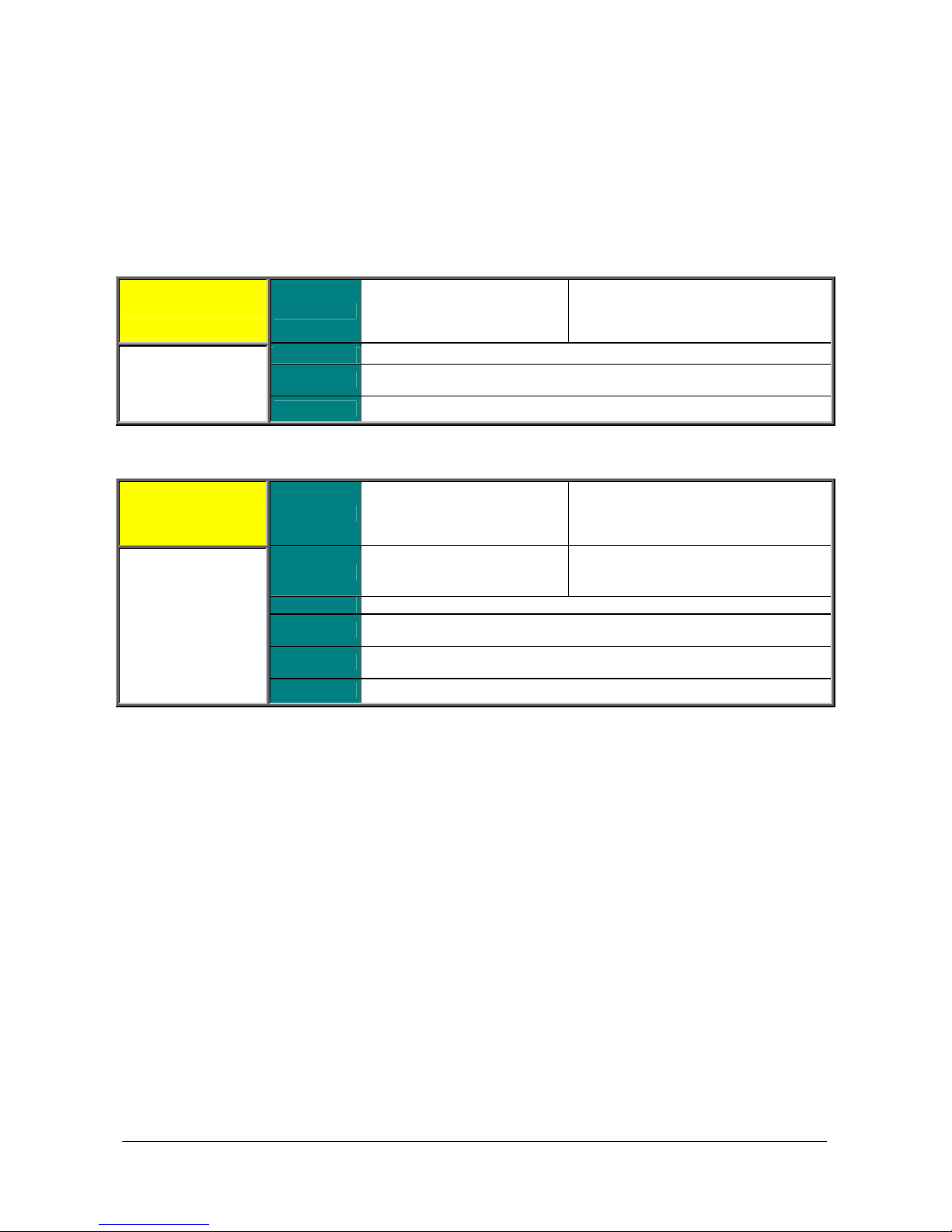
This optional field is displayed when a parameter is not active for all types of
INSTRUCTIONS
SINUS PENTA
0.4.3. MENUS AND SUBMENUS
This User Manual (Programming Instructions) is divided into different Menus. Their sequence is the same as their
display sequence in the display/keypad and the RemoteDrive software.
Programming parameters and Measure parameters are divided into:
Mxxx Measures (always Read Only):
Display on the display/keypad and the
RemoteDrive
(may be a decimal figure)
plus unit of measure
Display on the display/keypad and the
RemoteDrive
(may be a decimal figure)
plus unit of measure
Factory-setting of the parameter
(as displayed)
plus unit of measure
Mxxx Range
Pxxx Parameters (always R/W):
Pxxx Range
Drive representation
(integer)
Active Type of control (IFD / VTC / FOC) the measure is related to
Address
Function
Default
Level
Address
Control
Function
ModBus address which the measure can be read from
(integer)
Measure description
Drive representation
(integer)
Factory-setting of the parameter
(as represented for the drive)
User level (BASIC / ADVANCED / ENGINEERING)
ModBus address which the parameter can be read from
(integer)
motor controls (IFD / VTC / FOC)
Parameter description
11/452
Page 12
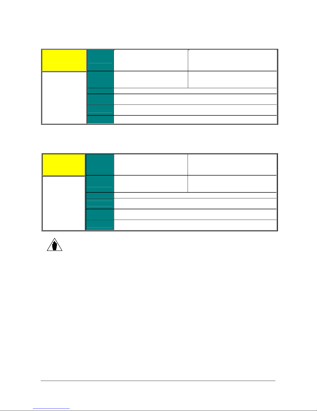
SINUS PENTA
This optional field is displayed when a parameter is not active for all types of
This optional field is displayed when a parameter is not active for all types of
PROGRAMMING
INSTRUCTIONS
Cxxx Parameters (Read Only when the drive is running and the motor is operating; R/W when the drive is in
stand-by or in Run, but the motor is stopped: see P003 in PASSWORD AND USER LEVEL MENU).
Display on the display/keypad and the
Cxxx Range
Default
Level
Address
Control
Function
Drive representation
(integer)
Factory-setting of the parameter
(as represented for the drive)
User level (BASIC / ADVANCED / ENGINEERING)
ModBus address which the parameter can be read from/written to
(integer)
motor controls (IFD / VTC / FOC)
Parameter description
Rxxx Parameters (Read Only when the drive is in Run; R/W when the drive is in stand-by or in Run, but the motor
is stopped: see P003 Condition required for changing C parameters in the PASSWORD AND USER LEVEL
MENU).
Rxxx Range
Default
Level
Address
Control
Function
Drive representation
(integer)
Factory-setting of the parameter
(as represented for the drive)
User level (BASIC / ADVANCED / ENGINEERING)
ModBus address which the parameter can be read from/written to
(integer)
motor controls (IFD / VTC / FOC)
Parameter description
Unlike Cxxx parameters, Rxxx parameters become active only after the drive has been
NOTE
switched off and switched on again, or after resetting its control board by pressing the
RESET button for more than 5 seconds.
RemoteDrive
(may be a decimal figure)
plus unit of measure
Factory-setting of the parameter
(as displayed)
plus unit of measure
Display on the display/keypad and the
RemoteDrive
(may be a decimal figure)
plus unit of measure
Factory-setting of the parameter
(as displayed)
plus unit of measure
12/452
Page 13
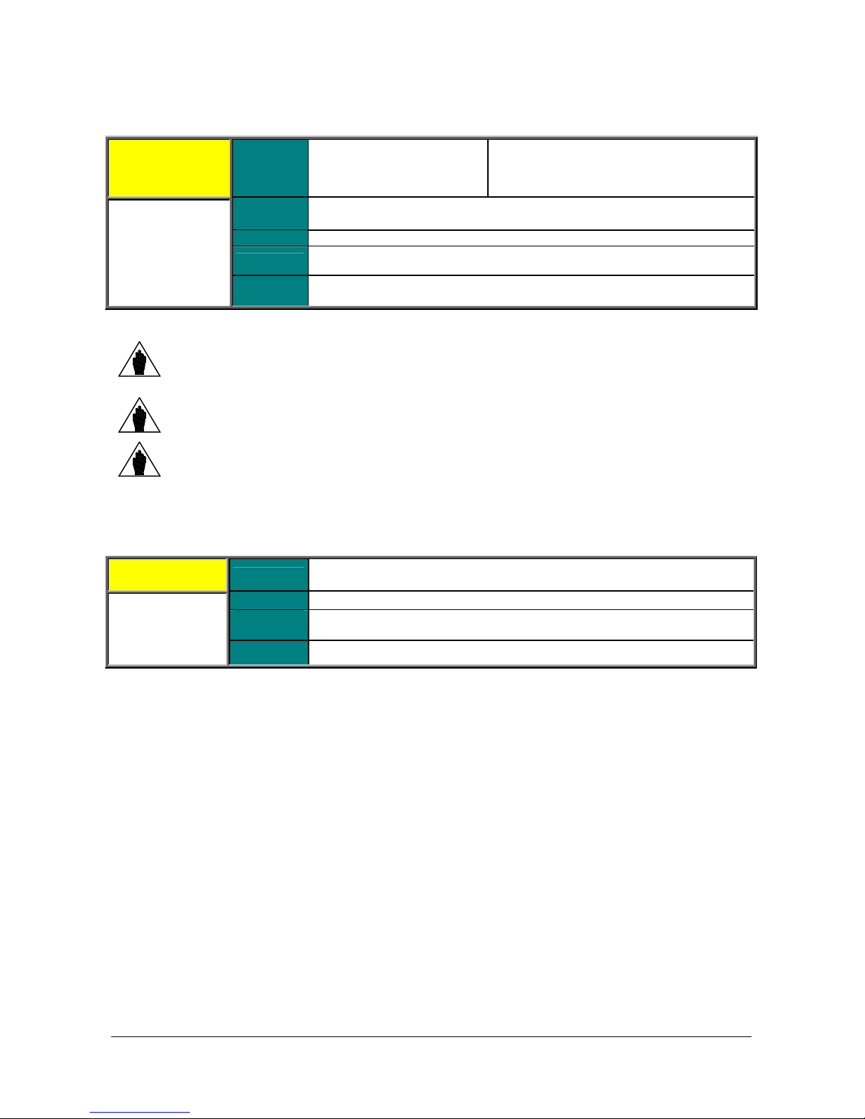
PROGRAMMING
This optional field is displayed when a parameter is not active for all types of
INSTRUCTIONS
SINUS PENTA
Ixxx Inputs. These are not parameters, but inputs (the values allocated to these inputs are not stored to non-volatile
memory. Ixxx value is always 0 when the drive is powered on).
Display on the display/keypad and the
RemoteDrive
(may be a decimal figure)
plus unit of measure
Ixxx Range
Drive representation
(integer)
Level
Address
Control
User level (BASIC / ADVANCED / ENGINEERING)
ModBus address which the input can be read from/written to (integer)
motor controls (IFD / VTC / FOC)
Function Input description
NOTE
NOTE
Use the ESC key to enter the value of an Ixxx input.
If the SAVE/ENTER key is used, W17 SAVE IMPOSSIBLE (warning) is displayed.
When changing a Pxxx or Cxxx parameter via the display/keypad, you may activate its new
value immediately (flashing cursor) or when you quit the programming mode (fixed cursor).
Typically, numeric parameters immediately come to effect, while alphanumeric parameters
have a delayed effect.
NOTE
0.4.4. ALARMS AND WARNINGS
When changing a Pxxx or Cxxx parameter via the RemoteDrive, the drive will immediately
use the new parameter value.
The last part of this User Manual covers alarms (Axxx) and warnings (Wxxx) displayed by the drive:
Axxx
Description
Event
Possible
cause
Solution
13/452
Page 14

SINUS PENTA
PROGRAMMING
INSTRUCTIONS
1. USING THE DISPLAY/KEYPAD UNIT
1.1. Overview
This section contains several examples about navigating in the display/keypad unit and the UPLOAD and DOWNLOAD
functions of the programming settings of the drive when using the keypad.
More details about the keypad settings (contrast, backlight, etc.) are given in the section covering the display/keypad in
the Installation Instructions Manual. Details about custom navigation in the root page, the measures in the Keypad
page and the Root page and the custom unit of measure of the PID controller are given in the DISPLAY/KEYPAD
MENU in this manual.
When using the navigation “by menu” mode (P264 = BY MENU), the structure of the menu tree that can be explored
using the display/keypad is described in the Menu Tree section.
The complete tree structure is displayed, but the actual structure depends on the user level set in P001 and on the
implemented programming. For example, if only motor 1 is programmed (C009=1), the menus relating to motors 2 and
3 will not be displayed (Motor 2/3 Configuration and Motor 2/3 Limit). Also, if the type of motor control is C010=IFD
Voltage/Freq., the BRIDGE CRANE MENU will not be displayed.
When P264 = Linear (linear navigation), the parameters displayed are no longer grouped into menus, and you can
scroll through all parameters using the ▲ and ▼ keys.
When P264 = Modified Pars. Only, only the parameters having different values than the factory settings are displayed,
and you can scroll through all parameters using the ▲ and ▼ keys.
The Navigation section shows how to use function keys to navigate through the parameters and to change parameter
values (P264 = BY MENU).
The function keys and their functionality are described below.
14/452
Page 15
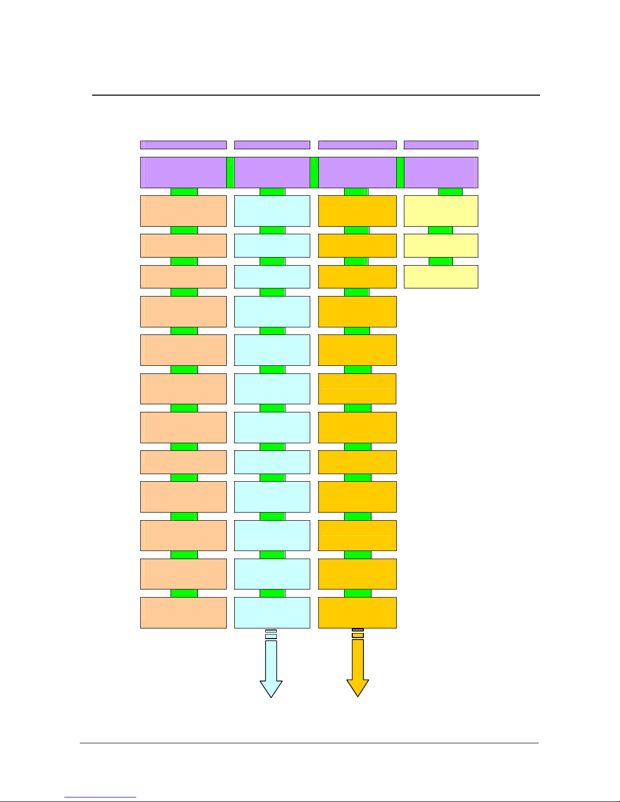
PROGRAMMING
INSTRUCTIONS
1.2. Menu Tree
MEASURES/COMMANDS PARAMETERS CONFIGURATION
INVERTER OK
M00=+0.00rpm
M02=+ 0.00 rpm
[MEA] PAR CF IDP
MEASURE MENU
M Parameters
Cannot be changed
[MEA]
MEASURES
[MEA]
PID REGULATOR
[MEA]
[MEA]
REFERENCES
[MEA]
OUTPUTS
[MEA]
TEMPERATURES
[MEA]
AUTODIAGNOSTICS
[MEA}
DATA LOGGER
MEASURES
[MEA]
DIGITAL INPUTS
SETTINGS
[MEA]
[MEA]
POWER OFF
MOTOR
DIGITAL
INPUTS
PT100
FAULT
LIST
LIST
INVERTER OK
M00=+0.00rpm
M02=+ 0.00 rpm
MEA [PAR] CF IDP
PARAMETERS MENU
P Par. that can
be changed when the
motor is running
[PAR]
PASSWORD AND
ACCESS LEVEL
[PAR]
DISPLAY/KEYPAD
[PAR]
[PAR]
[PAR]
PAR]
[PAR]
PAR]
PAR]
[PAR]
[PAR]
RAMPS
INPUTS FOR
REFERENCES
MULTISPEED
PID
MULTIREFERENCES
PROHIBIT
SPEED
REFERENCE
VARIATION
PERCENT
SPEED LOOP AND
CURRENT BALANCE
“FOC” FIELD
ORIENTED CONTROL
ANALOG OUTPUTS
AND FREQUENCY
OUTPUTS
INVERTER OK
M00=+0.00rpm
M02=+ 0.00 rpm
MEA PAR [CF] IDP
CONFIGURATION MENU
C-I-R Parameters
can be changed
when motor off
[CFG]
AUTO TUNE
[CFG]
MODULATION
FREQUENCY
[CFG]
MOTOR N.1 / 2 / 3
CONFIGURATION
[CFG]
MOTOR N.1 / 2 / 3
LIMITS
[CFG]
CONTROL METHOD
[CFG]
[CFG]
[CFG]
[CFG]
[CFG]
[CFG]
DIGITAL
INPUTS
ENCODER/
FREQUENCY INPUTS
BRAKING
UNIT
DC BRAKING
MAINS LOSS
SPEED SEARCH
PRODUCT IDENTIFIER
Press ENTER to start
[IDP]
SINUS PENTA
INVERTER OK
M00=+0.00rpm
M02=+ 0.00 rpm
MEA PAR CF [IDP]
PRODUCT MENU
Language
Selection and
Inverter Data
[IDP] SINUS PENTA
START-UP MENU
PRODUCT
15/452
Page 16
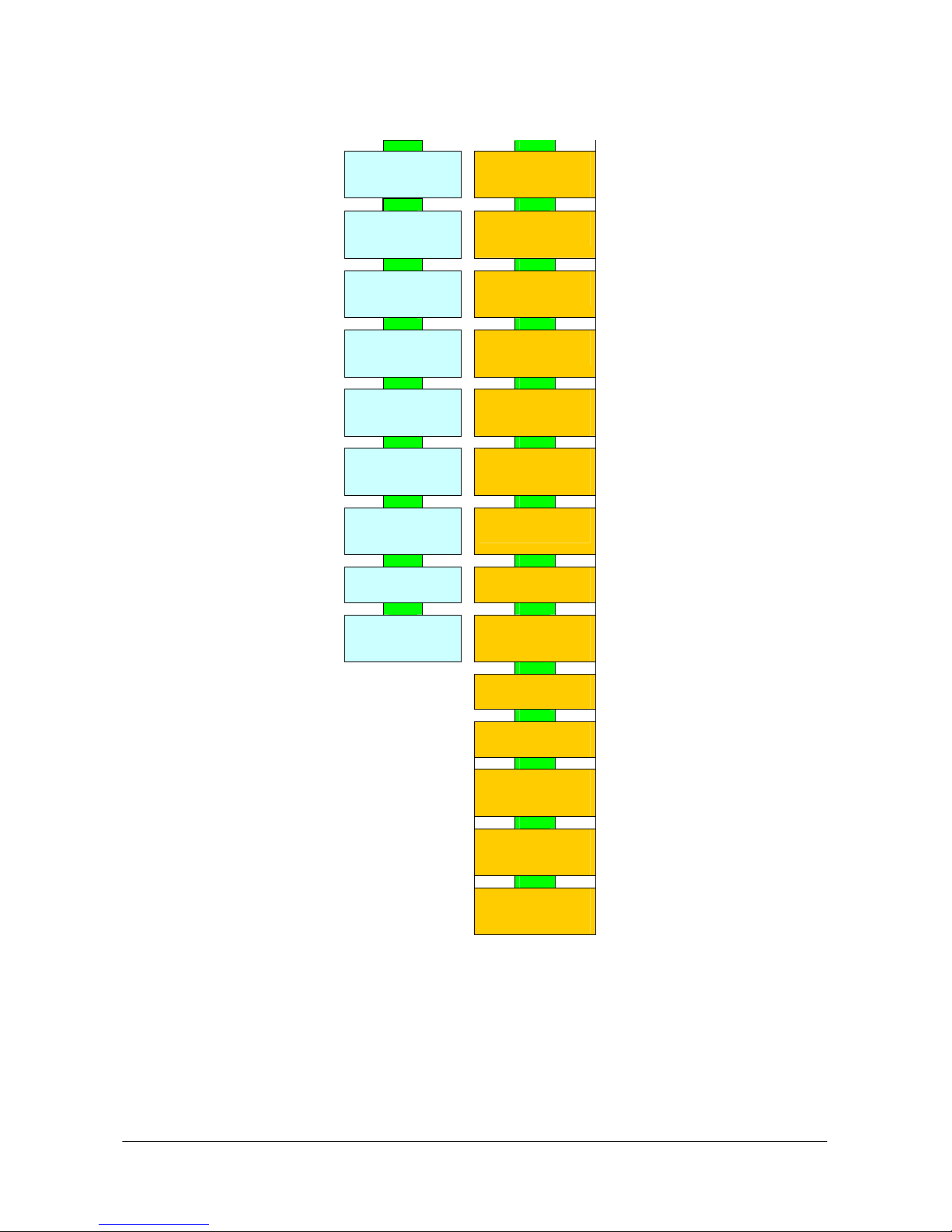
SINUS PENTA
PROGRAMMING
INSTRUCTIONS
Figure 1: Menu Tree.
[PAR]
TIMERS
[PAR]
[PAR]
[PAR]
[PAR]
[PAR]
[PAR]
[PAR]
[PAR]
REFERENCES FROM
PID
PARAMETERS
PID2
PARAMETERS
DIGITAL
OUTPUTS
AUXILIARY DIGITAL
OUTPUTS
PT100 MEASURE
SETTINGS
FIELDBUS
PARAMETERS
VIRTUAL DIGITAL
OUTPUTS
INPUTS FOR
ES847
[CFG]
[CFG]
[CFG]
[CFG]
[CFG]
[CFG]
[CFG]
[CFG]
[CFG]
[CFG]
[CFG]
[CFG]
[CFG]
[CFG]
ALARM
AUTORESET
THERMAL
PROTECTION
MAINTENANCE
TIME COUNTERS
PID
CONFIGURATION
BRIDGE CRANE
DATE AND TIME
TIMED FLAGS
SERIAL LINKS
FIELDBUS
CONFIGURATION
EXPANSION BOARD
SETTINGS
PROFIDRIVE BOARD
CONFIGURATION
DAYLIGHT
SAVING TIME
DATA LOGGER
EEPROM
16/452
Page 17
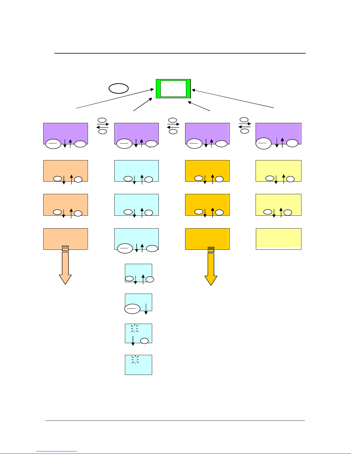
PROGRAMMING
d
MENU
INSTRUCTIONS
1.3 Navigation
SINUS PENTA
Figure 2: Navigation example.
Keypa
INVERTER OK
M00=+0.00rpm
M02=+ 0.00 rpm
[MEA] PAR CF IDP
SAVE
ENTER
MEASURE MENU
M Parameters
Cannot be changed
[MEA]
MOTOR
MEASURES
[MEA]
PID REGULATOR
ESC
INVERTER OK
PARAMETERS MENU
[PAR]
M00=+0.00rpm
M02=+ 0.00 rpm
MEA [PAR] CF IDP
SAVE
ENTER
P Pars. that can
be changed when the
motor is running
PASSWORD AND
ACCESS LEVEL
[PAR]
Access to
Ramps
menu
DISPLAY/KEYPAD
SAVE
ENTER
P009 Acceler.
Ramp 1
10.00s
ES
ESC
INVERTER OK
CONFIGURATION M.
[CFG]
[CFG]
M00=+0.00rpm
M02=+ 0.00 rpm
MEA PAR [CF] IDP
SAVE
ENTER
C-I-R Parameters
Can be changed
when motor off
AUTO TUNE
CONFIGURATION OF
MOTOR N. 1
ESC
INVERTER OK
M00=+0.00rpm
M02=+ 0.00 rpm
MEA PAR CF [IDP]
SAVE
ENTER
PRODUCT MENU
Language selection
and Inverter data
ESC
[IDP]SINUS PENTA
Start-Up Menu
Press ENTER to start
[IDP]
PRODUCT
Navigation within
Ramps
menu
Access to
parameter
modification P010
Parameter
modification P010
If the ESC key is pressed to quit, the new parameter
value will be acknowledged but not saved to non-volatile
memory, and will therefore be lost at power off. Press
SAVE/ENTER to confirm parameter alteration.
P010 Deceler.
Ramp 1
10.00s
SAVE
ENTER
P010 Deceler.
Ramp 1
█ 10.00s
P010 Deceler.
Ramp 1
█ 20.00s
17/452
Page 18

SINUS PENTA
PROGRAMMING
INSTRUCTIONS
1.4. Parameter Modification
Factory setting allows parameter modification. The parameters included in the Parameters Menu (Pxxx parameters)
can be changed at any moment, whereas the parameters included in the Configuration Menu (Cxxx, Rxxx, Ixxx
parameters) can be changed only when the motor is stopped.
For safer operating conditions, the configuration parameters must be changed only when the drive is disabled (the
ENABLE command is inactive): to do so, P003 must be set to 0 (stand-by only).
To disable parameter changes, just change P000 (write enable) and save its new setting. P000 and P002 (password)
are both factory-set to 1. If P000=0, an inexpert user cannot change parameter values, but if P000=1, an advanced
user will be able to change the parameter values.
For even safer operating conditions, you can change the password stored in P002; in that case, you must set P000
accordingly.
NOTE Note down and keep at hand the value set in P002.
Press the SAVE/ENTER key for parameter modifications; when a flashing cursor appears, press ▲ and ▼ to change
the parameter value. Do one of the following to quit the editing mode:
Press ESC the parameter value used by the drive is changed and is maintained until the drive is shut down.
Press SAVE/ENTER the parameter value is stored to non-volatile memory and is not deleted when the drive is shut
down.
Inputs (Ixxx) cannot be saved to non-volatile memory and are automatically set to their default values.
Rxxx parameters become active only when the drive control board has been reset by pressing the RESET key for a few
seconds or by switching off the drive.
1.5. Programming the Root Page
When the drive is turned on, the Root page is displayed as the starting page. The Root page allows you to access the
main menus (Measures, Parameters, Configuration, Product ID) or to shift to the Keypad pages using the MENU key.
I N V E R T E R O K
+ 1 5 0 0 . 0 0 r p m
+ 0 . 0 0 r p m
M E A [ P A R ] C F I D P
You can customise the root page using parameter P265 (see the DISPLAY/KEYPAD MENU).
Root page
18/452
Page 19
PROGRAMMING
S T A R T - U P
P r e s s E N T E R
m
m
mR e f
m
mT L i m
m
m
m
MENU
MENU
MENU
MENU
MENU
INSTRUCTIONS
SINUS PENTA
1.6. Using the MENU Key
The MENU key allows going to the next menu. From the Root page, press the MENU key to enable circular navigation.
A N Y P A G E
I N A M E N U
Start-Up Menu [*]
[ I D P ] S I N U S P E N T A
M E N U
t o s t a r t
Measures Page
+
+
+
+
0 . 0 0 r p
0 . 0 0 r p
0 . 0 H z
0 . 0 A
KEYPAD Pages (if any…)
+
+
+
+
0 . 0 H z
0 . 0 A
0 . 0 0 r p
1 5 0 0 . 0 0 r p
…KEYPAD Pages (continued) [**]
+
+
+
+
0 . 0 H z
0 . 0 A
0 . 0 0 r p
1 5 0 . 0 N
Root Page
I N V E R T E R
M E A P A R C F [ I D P ]
+
1 5 0 0 . 0 0 r p
+
O K
0 . 0 0 r p
NOTE [*] The Start-Up menu is available only if P265=3:Start-Up (see the DISPLAY/KEYPAD MENU).
NOTE [**]
The Keypad pages are available only if the relevant references / feedback / limits are activated
(see the CONTROL METHOD MENU and the PID CONFIGURATION MENU).
19/452
Page 20
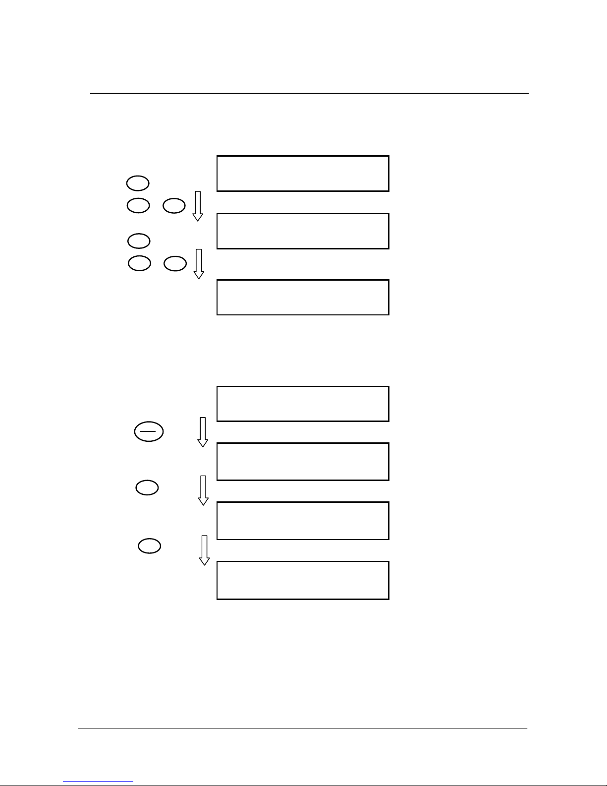
SINUS PENTA
E S C
E S C >
E S C >
E S C >
▲ ▼
ESC or
▲ ▼
ESC or ESC
▼
PROGRAMMING
INSTRUCTIONS
1.7. ESC Key
Press the ESC key and to move up one level in the menu tree.
In the example below, starting from parameter C015 in the MOTOR CONTROL MENU inside the Configuration Menu,
you can move up to the Root page by pressing the ESC key.
Page C015 Parameter of Configuration Menu, Motor 1
C 0 1 5 N O M I N A L
F r e q u e n c y
m o t o r 1
5 0 . 0 H z
When using the SAVE/ENTER key to change a parameter including multiple fields (ESC> is displayed for the ESC key)
press ESC to move to the next field. In the example below, 2 programmable fields are displayed for P269:
Press the following keys to quit the last page displayed:
ESC (new values are not saved to Eeprom)
SAVE/ENTER (new values are saved to Eeprom).
SAVE
ENTER
Startup Page of Configuration Menu, Motor 1
[ C F G ]
C O N F I G U R A T I O N
M O T O R N . 1
Root page
I N V E R T E R O K
+ 1 5 0 0 . 0 0 r p m
+ 0 . 0 0 r p m
M E A P A R [ C F ] I D P
P 2 6 9 D i s a b l e
K e y s :
L O C / R E M F W D / R E V
> N O N O
Press “SAVE/ENTER” to enter the editing mode
P 2 6 9 D i s a b l e
K e y s :
L O C / R E M F W D / R E V
N O N O
Press “▼ ” to change the parameter value
P 2 6 9 D i s a b l e
K e y s :
L O C / R E M F W D / R E V
Y E S N O
Press “ESC” to move to the next field
P 2 6 9 D i s a b l e
K e y s :
L O C / R E M F W D / R E V
Y E S N O
20/452
Page 21
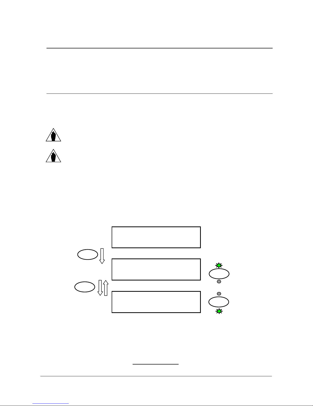
PROGRAMMING
p
WN L O A D
p
TX/RX
TX/RX
TX/RX
TX/RX
INSTRUCTIONS
SINUS PENTA
1.8. RESET Key (Alarm and Control Board Reset)
The RESET key is used to reset the drive after an alarm trips and the cause responsible for the alarm has been
removed.
Press the RESET key for more than 5 seconds to reset the control board and reinitiate it. This procedure may be
useful when changes made to Rxxx parameters (which activate only after resetting the equipment) must immediately
come to effect, with no need to switch off the drive.
1.9. TX/RX Key (Download/Upload from/to the Keypad)
Use the keypad to perform the UPLOAD (parameters stored in the drive are copied to the keypad) and DOWNLOAD
(parameters stored in the keypad are copied to the drive) functions.
Press the TX/RX key to go to the UPLOAD page; press the TX/RX key again to toggle between the UPLOAD and
DOWNLOAD pages.
The TX/RX key is disabled under the following conditions:
In the example below, you can go to the UPLOAD page from any page (the upper LED starts flashing). If you then
press the TX/RX key, you can go to the UPLOAD and DOWNLOAD pages.
A Warning is displayed (one among W41 to W46) when trying to DOWNLOAD
NOTE
parameters to a drive whose SW Version, IDP, PIN or current/voltage classes are
different from those of the drive previously used for parameter UPLOAD. In that case,
download is not allowed.
The DOWNLOAD function allows the parameters stored in the keypad to be copied to
the drive. However, parameters are not stored to the non-volatile memory of the drive.
NOTE
To store the downloaded parameters to the non-volatile memory of the drive, go to the
EEPROM menu and execute a “Save Work” command once the download procedure is
complete. Otherwise, when power is lost, the parameters downloaded to the drive are
lost.
no password is entered in P000
the OPERATOR mode is activated with the MENU Key (P264b = OPERATOR)
the drive is running.
Any page
A N Y
P A G E
UPLOAD Page
P a r a m e
t
e r U P L O A D
i n v e r t e r k e y p a d :
r e s s
t o c o n f i r m
S A V E / E N T E R
DOWNLOAD Page
P a r a m . D
k e y p a d
r e s s
O
i n v e r t e r :
S A V E / E N T E R
t o c o n f i r m
Press SAVE/ENTER from the UPLOAD (/DOWNLOAD) page to confirm UPLOADING (/DOWNLOADING). The
relevant LED will come on (fixed light).
If the SAVE/ENTER key is not pressed for confirmation within 10 seconds from the selection of the UPLOAD
(/DOWNLOAD) page, the starting page is automatically displayed.
While UPLOADING, W08 UPLOADING (flashing warning) appears.
If parameters are successfully uploaded, the following warning appears:
W11 UPLOAD OK
If not, the W12 UPLOAD KO warning appears. Retry parameter upload
.
21/452
Page 22

SINUS PENTA
PROGRAMMING
INSTRUCTIONS
While DOWNLOADING, W07 DOWNLOADING (flashing warning) appears.
If parameters are successfully downloaded, the following warning appears:
W09 DOWNLOAD OK
If not, alarm A073 trips, and download must be retried before restarting the drive.
1.10. LOC/REM Key (Keypad Pages)
To enable the Local/Remote operating mode (Remote sources are command and/or reference sources other than the
display/keypad) press the LOC/REM key in the display/keypad, or use a digital input configured as Loc/Rem (see
C180).
The LOC/REM key is enabled when no digital input is configured as Loc/Rem, or when a
NOTE
C148 sets whether toggling between Remote mode and Local mode is activated only when the drive is disabled, or
whether toggling from Remote to Local mode does not affect the drive running conditions (bumpless commands), but it
does affect the reference. You can also choose to keep running conditions and reference unaffected (any command is
bumpless). For more details, please refer to the description of parameter C148 (CONTROL METHOD MENU).
In LOCAL mode (the L-CMD and L-REF LEDs come on), when drive references and commands are sent via
display/keypad, the Keypad page allows changing the given reference using the ▲ and ▼ keys (see P266 in the
DISPLAY/KEYPAD menu).
When not in LOCAL mode, press the MENU key to access the Keypad pages from the root page. Only the Keypad
pages relating to the Keypad source will be displayed along with the Measure Keypad page.
Example: Parameter C147 (Torque Limit Reference Selection) is set to Keypad. From the root page, press the MENU
key once to display the Measure Keypad page, and press the MENU key twice to display the Keypad page relating to
the torque limit and allowing changing the torque limit reference using the ▲ and ▼ keys.
The Keypad page allows entering custom measures (see parameters P268b to P268e in the DISPLAY/KEYPAD
menu).
From the Keypad pages, press the SAVE/ENTER key to access the Keypad Help page containing any details about the
measures displayed in the Keypad page.
digital input is configured as a Loc/Rem button (see C180a).
The LOC/REM key is disabled when a digital input is configured as a Loc/Rem selector switch
(see C180a).
1.11. SAVE/ENTER Key
The SAVE/ENTER key allows selecting a lower level when navigating within the programming menus. It also allows
changing a parameter value (to change a parameter value, press the SAVE/ENTER key from the page of the
parameter you want to change). An example is given in Figure 2.
From the Keypad pages, the SAVE/ENTER key allows accessing the Keypad Help page containing any details about
the measures displayed in the Keypad page.
22/452
Page 23
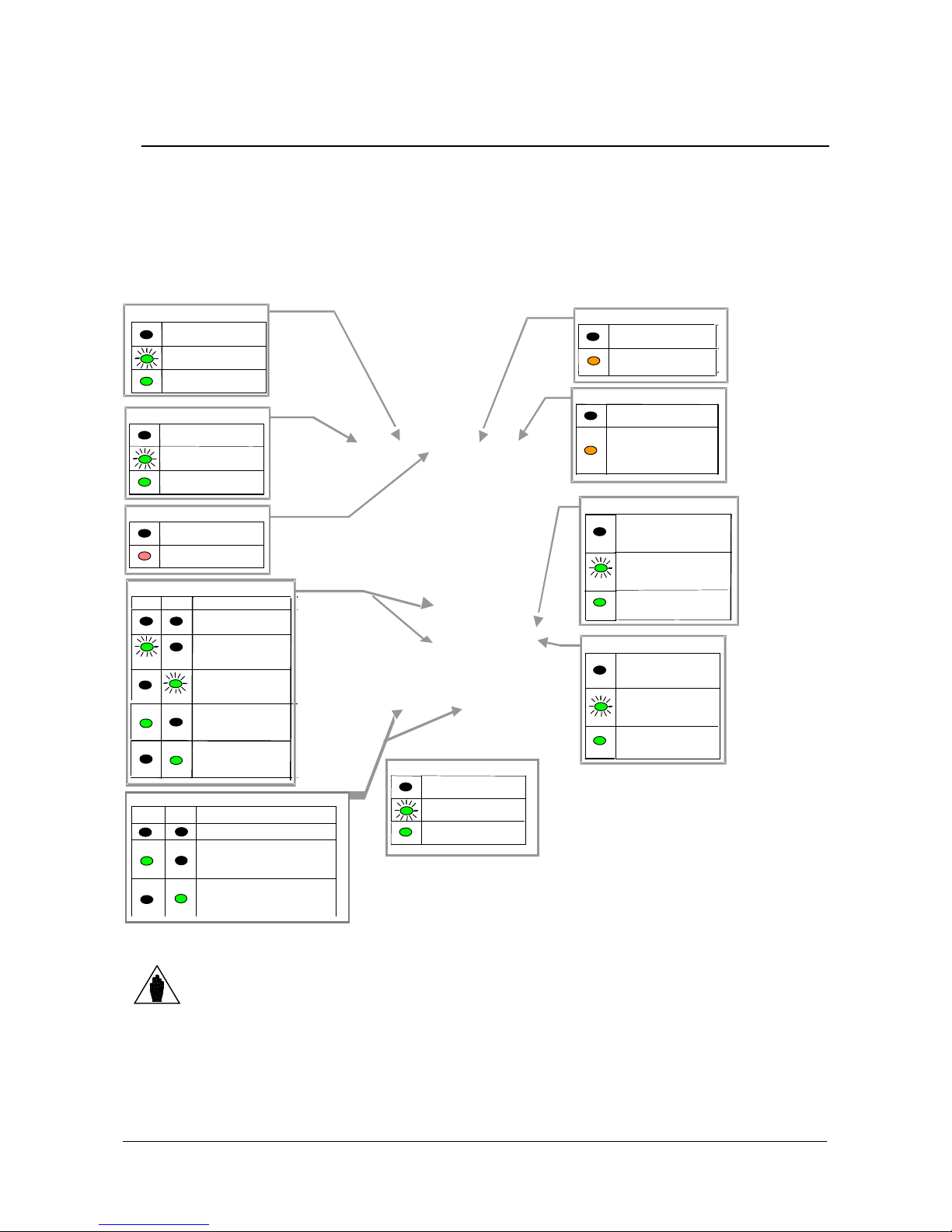
PROGRAMMING
ALARM LED
-
Red
RUN LED
-
Green
Motor not
and running
REF LED
-
Green
frequency or torque =
LIMIT LED
-
Yellow
No active limit
limit active
BRAKE LED
-
Yellow
-
-
-
keypad
Commands sent
from keypad only
LED off
LED on (fixed)
Reference sent
both from keypad
and
terminal board
L-REF LED
-
Green
is being sent and is
TX and RX LEDs
-
Green
TX
RX
No parameter
INSTRUCTIONS
SINUS PENTA
1.12. Indicator LEDs on the Display/Keypad
Eleven LEDs are located on the keypad, along with a 4-line, 16-character LCD display, a buzzer and 12 function keys.
The display shows the parameter values, the diagnostic messages and the variables processed by the drive.
The figure below shows the location of the indicator LEDs and their functionality.
Figure 3: Display/keypad.
Reference for speed,
Motor
Reference on
Motor powered,
Motor powered
Inverter OK
Alarm tripped
FWD and REV LEDs – Green
FWD REV
transfer in progress
Download:
waiting
Upload: waiting
for confirmation
Parameter
downloading from
keypad to inverter
Parameter
uploading from
inverter to
Total reference = 0
Total reference of
frequency/ speed/torque
is being sent and is positive
Total reference of
frequency/ speed/torque
Voltage or current
Ordinary run
LED flashing
Either one is active:
L-CMD LED – Green
DC current brake
IGBT braking
Ramp extension.
Commands sent from
sources other than
Commands sent
both from keypad
and terminal board
Reference sent from
sources other
than keypad
Reference sent from
keypad only
NOTE
See also the OPERATING AND REMOTING THE KEYPAD section in the Sinus Penta’s
Installation Instructions manual.
23/452
Page 24
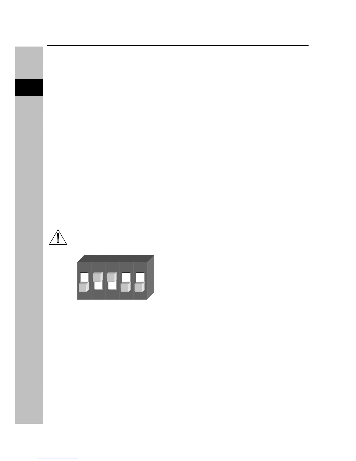
1 2 3 4 5 6 7 8 9 10 11 12 13 14 15 16 17 18 19 20 21 22
PROGRAMMING SINUS PENTA
INSTRUCTIONS
0
2. DESCRIPTION OF INPUT AND OUTPUT SIGNALS
The control board of the drives of the Sinus Penta series is provided with the following inputs/outputs:
3 Analog Inputs (single-ended REF input, differential AIN1 & AIN2 inputs) that can be programmed as
voltage/current inputs via SW1 DIP-switch (see Configuration DIP-switches in the Sinus Penta’s Installation
Instructions Manual).
3 Analog Outputs that can be programmed as voltage/current inputs via SW2 DIP-switch (see Configuration
DIP-switches in the Sinus Penta’s Installation Instructions Manual).
8 MDI Multifunction Digital Inputs; 3 of them (MDI6, MDI7, MDI8) are fast-acquisition inputs allowing acquiring
frequency signal or encoder signals.
MDI6 can be used to acquire a frequency signal called FINA; if used in conjunction with MDI7, it also allows
acquiring a push-pull encoder signal called Encoder A.
MDI8 can be used to acquire a frequency input called FINB (this avoids acquiring encoder B via ES836 or ES913
option board).
4 MDO Multifunction Digital Outputs; MDO1 is a Push-pull output, MDO2 is an Open Collector output and
MDO3-4 are relay outputs.
Electrical ratings of the control board inputs/outputs are given in the Sinus Penta’s Installation Instructions Manual.
When programming:
Analog Inputs, see the INPUTS FOR REFERENCES MENU
Analog Outputs, see the ANALOG AND FREQUENCY OUTPUTS MENU
Digital Inputs, see the DIGITAL INPUTS MENU
Digital Inputs used as Frequency/Encoder Inputs, see the ENCODER/FREQUENCY INPUTS MENU
Multifunction Digital Outputs, see the DIGITAL OUTPUTS MENU
The drive is factory-set with the REF input configured as 0-10V and AIN1-AIN2 inputs
CAUTION
ON
configured as 4-20mA.
SW1 dip-switches, which are located on the control board, must be set as follows:
SW1
1
2
3
4
5
24/452
Page 25

PROGRAMMING
INSTRUCTIONS
SINUS PENTA
3. REFERENCES AND FEEDBACKS
The drive references are the following:
Main speed/torque reference
Speed/torque limit reference
PID reference
PID feedback
3.1. Main Speed/Torque Reference
If a speed control (e.g. C011 = Speed for Motor 1) is used, the main reference is a speed reference, while if a
torque control is used (e.g. C011=Torque or C011=Speed for Motor 1, but the digital input is closed for the Slave
programmed with C170), the main reference of the drive is a torque reference.
The main reference can be one of the following:
Analog/digital inputs programmed as sources (see parameters C143-C146 in the CONTROL METHOD
MENU)
PID output if C294 PID Action = Reference
Digital inputs programmed as Multispeed (see MULTISPEED MENU) only when the main reference is a
speed reference.
3.2. Speed/Torque Limit Reference
If a speed control is used (e.g. C011 = Speed for Motor 1) and a VTC or FOC algorithm is used, you can program a
source as an external torque limit (see parameter C147 in the CONTROL METHOD MENU).
If a torque control is used and an external speed limit has been set up (e.g. C011 = Torque with Speed Limit for
Motor 1) and a FOC algorithm is used, you can program one source as an external speed limit (see parameter C147 in
the CONTROL METHOD MENU).
3.3. PID Reference
If the internal PID regulator is enabled (C291 different from Disabled), its reference is given by default by the sum of
the three sources programmed as references (see parameters C285-C287 in the PID CONFIGURATION MENU).
Different types of PID reference control (Two PIDs and 2-zone mode) are available based on the setting in parameter
C291a (PID Control Mode).
3.4. PID Feedback Reference
The PID feedback by default is the sum of the three sources programmed as feedback (see parameters C288-C290 in
the PID CONFIGURATION MENU).
Different types of PID feedback control (Two PIDs and 2-zone mode) are available based on the setting in parameter
C291a (PID Control Mode).
25/452
Page 26

SINUS PENTA
PROGRAMMING
INSTRUCTIONS
4. PROGRAMMABLE FUNCTIONS
4.1. Multimotor
The Sinus Penta drive provides 3 separate sets of parameters allowing configuring three control algorithms for 3 types
of motors:
C009 Number of configured motors =2
C173 Digital input for Motor 2 = MDI6
When MDI6 is open, the parameters relating to Motor 1 are used for the motor control; when MDI6 is closed, the
parameters relating to Motor 2 are used for the motor control (see the MOTOR CONTROL MENU and the
MULTISPEED MENU).
4.2. Voltage/Frequency Pattern
When using a Volt/Freq IFD control algorithm (e.g. C010 = V/F IFD for Motor 1), you can select different types of V/f
patterns (see the V/f Pattern (IFD Only) section).
4.3. Slip Compensation
When using a Volt/Freq IFD control algorithm (e.g. C010 = V/F IFD for Motor 1), you can set the slip compensation
function for a more accurate speed control (see the Slip Compensation (IFD Only) section).
4.4. Speed Searching
When using a Volt/Freq IFD control algorithm (e.g. C010 = V/F IFD for Motor 1), you can set the speed searching
function for the motor speed of rotation, which is useful when the drive controls a motor which is already running (as
for motors connected to fans). See the SPEED SEARCHING MENU for more details.
4.5. Controlled Stop in Case of Power Failure (Power Down)
See the POWER DOWN MENU to set a controlled stop in case of power failure.
4.6. DC Braking
When using a Volt/Freq IFD or Vector Torque VTC control algorithm, you can set DC braking at start or at stop. The
DCB Hold function can be set for the Volt/Freq IFD function. See the DC BRAKING MENU for more details.
4.7. Motor Thermal Protection
The Motor Thermal Protection function protects the motor against possible overloads. This function can be obtained via
a PTC acquired in AIN2 analog input—up to 6 PTCs can be series-connected—or it can be a software protection
implemented through an algorithm reproducing the motor thermal image.
See the MOTOR THERMAL PROTECTION MENU for more details.
For more details about using AIN2 input, please refer to the Sinus Penta’s Installation Instructions Manual.
26/452
Page 27

PROGRAMMING
INSTRUCTIONS
SINUS PENTA
4.8. Prohibit Speeds
Prohibit speeds are speed ranges corresponding to mechanical resonance frequencies. They prevent the drive from
running at the preset speed ranges.
See the PROHIBIT SPEED MENU for more details.
4.9. Digital PID Regulator
The Sinus Penta drive is provided with a digital PID (proportional, integral, derivative) regulator that can be used to
implement the following:
Analog output
Main reference of the drive (Speed/Torque reference)
Correction of the main reference
Correction of the output voltage (only for Volt/Freq IFD control)
See the PID PARAMETERS MENU and the PID CONFIGURATION MENU for more details.
4.10. Bridge Crane Application
For lifting applications, such as a bridge crane, it may be useful to consider the actual time required to release the
safety electromechanical brake (the delay between the electrical command and the actual opening of the brake) and
the closure of the electromechanical brake.
For a detailed description of the benefits offered by the parameters relating to lifting applications, see the BRIDGE
CRANE MENU.
4.11. Setting Two Alternative Command Sources and
Reference Sources
You can set a digital input as a selector switch allowing selecting two alternative control sources and reference
sources.
Example:
A selector switch is required to select control mode B (the drive references and commands are sent via fieldbus) and
control mode A (the drive reference is sent via AIN1 analog input and commands are sent via keypad).
The following parameters shall be set up accordingly:
C179 MDI for source selection= MDI6
C140 Selection of control source n. 1 = Keypad
C141 Selection of control source n. 2 = Fieldbus
C143 Selection of reference n. 1 = AIN1
C144 Selection of reference n. 2 = Fieldbus
When MDI6 digital input in the terminal board is open (terminal 19), the command sources and reference sources n. 1
are selected (Keypad and AIN1 analog input, control mode A). When MDI6 is closed, the command sources and
reference sources n. 2 are selected (Fieldbus, control mode B).
In the example above, if C179 = Disable, the OR logic for the Keypad and Fieldbus is
CAUTION
See also parameter C179 in the DIGITAL INPUTS MENU.
considered, whereas the Fieldbus and AIN1 control sources are considered as summed
up.
27/452
Page 28
SINUS PENTA
PROGRAMMING
INSTRUCTIONS
4.12. Fire Mode
When the digital input programmed as FIRE MODE is activated, all the protecting functions of the drive are ignored, so
that no alarm trips when the drive is operating.
The Fire Mode function must be used only when it is strictly necessary, such as in
CAUTION
NOTE
The following parameters can be accessed only after entering the Password enabling the Fire Mode:
P032 Acceleration Ramp in Fire Mode (see the RAMPS MENU)
P033 Deceleration Ramp in Fire Mode (see the RAMPS MENU)
P099 Speed Fire Mode (see the MULTISPEED MENU)
C186 MDI Enabling Fire Mode (see the DIGITAL INPUTS MENU)
The Fire Mode is enabled when closing the MDI set through C186. The drive will use the speed reference set in P099
and the ramp times set in P032, P033. All alarms will be ignored, except for the following:
A041
A044
A048
A050
A051
A053
When the Fire Mode is active, innumerable alarm autoresets are automatically enabled.
CAUTION
fire pumps, to protect human lives.
This function must never be used to prevent alarms from tripping in domestic or
industrial applications.
To activate the parameters relating to the Fire Mode, enter the Password in the PRODUCT
MENU .
This Password is provided by BCH ELECTRIC LTD’s Service Department. The drive Serial
Number is required (see the Serial Number parameter in the PRODUCT MENU ).
IGBT FAULT Side A IGBT Hardware Side A, general alarm
OVERLOAD SW Software Overcurrent
OVER VOLTAGE DC-bus voltage exceeding Vdc_max
IGBT FAULT A Hardware Fault from IGBT Drive, side A
OVERLOAD HW A Hardware Overcurrent, side A
PWMA Not ON Hardware Failure, Side A IGBT cannot be fired
Control Board Failure
If an asterisk (*) appears next to INVERTER OK on the display, the product
guarantee is no longer valid.
The asterisk appears if at least one condition requiring the activation of a
protection feature occurs when the inverter is running in Fire Mode.
28/452
Page 29
PROGRAMMING
INSTRUCTIONS
SINUS PENTA
5. PROGRAMMING EXAMPLES
5.1. Overview
This section illustrates some programming examples for particular functions of the Penta drive. Flowcharts are used for
easier reference.
For any detail concerning individual parameters, see the relevant sections in this manual.
5.2. Programming a Reference
Torque
Flowchart A
Speed/Torque
Reference
PID
PID Ref./Fdb Speed/
Flowchart B
29/452
Page 30
SINUS PENTA
min. torque,
C048
for max. torque)
Setting
FLOWCHART A
P000 Write Enable
P001 = Eng. (User Level)
In the Motor 1 Configuration menu, select the
type of speed/torque reference (C011). The
Control Method menu includes the parameters
selecting the reference source.
You can set up to four sources, which are
summed up to each other. For speed control,
and if references are to be sent also from digital
inputs, see the Multispeed menu.
Forcing the Reference Sources
Sources:
REF Ref Analog Input
AIN1 AIN1 Analog Input
AIN2 AIN2 Analog Input
Pulse Input Frequency Input
(MDI8)
Encoder Encoder
The reference scaling is obtained
through the parameters included in
the Input Reference menu. Each
source is assigned to a parameter
setting its min. value and max. value
for the min./max. speed/torque
reference of the connected motor
(e.g. Motor 1 speed reference: C028
for min. speed, C029 for max. speed.
Torque reference:
C047 for min. torque, C048 for max.
PROGRAMMING
INSTRUCTIONS
Selecting the Reference Sources
Sources :
Serial Link Reference from serial
link
Fieldbus Reference from fieldbus
Keypad Ref. from
display/keypad
Preset Speed Reference from digital
No reference scaling is required. Speed
references are expressed in rpm, torque
references are expressed as a percentage
of the motor rated torque. Saturation of the
reference values depends on Min. Speed
and Max. Speed parameters (speed
control), and on Min. Torque and Max.
Torque parameters (torque control). (E.g.
Motor 1 speed: C028 for min. speed, C029
for max. speed; Motor 1 torque: C047 for
30/452
Page 31
PROGRAMMING
Reference/Feedback
Sources
Rated voltage of the selected motor (Mot.1
Setting
INSTRUCTIONS
FLOWCHART B
The reference scaling is obtained through
the parameters included in the Reference
menu. Each source is assigned to a
parameter setting its min. value and max.
value for the min./max. PID
Reference/Feedback value.
See the PID Parameters menu.
Reference P245 Min., P246 Max.
Feedback P247 Min., P248 Max.
P000 Write Enable
P001 = Eng. (User Level)
Sources:
REF Ref Analog Input
AIN1 AIN1 Analog Input
AIN2 AIN2 Analog Input
Pulse Input Frequency Input (MDI8)
Encoder Encoder Input
SINUS PENTA
Selecting the
The PID Configuration menu includes
the parameters selecting the
reference/feedback source.
You can set up to three sources, which
are summed up to each other.
Forcing the
Reference/Feedback
Sources :
Serial Link Reference from serial link
Fieldbus Reference from fieldbus
Keypad Ref. from display/keypad
Feedback reference only :
Iout Output current
Vout Output voltage
Vdc DC bus voltage
No reference scaling is required. References
are expressed as a percentage. As a
feedback reference, output current (Iout),
output voltage (Vout), DC bus voltage (Vdc)
are available, which refer (as full-scale values)
to the following:
Rated current of the selected motor (Mot.1
C018)
31/452
Page 32

SINUS PENTA
PROGRAMMING
INSTRUCTIONS
EXAMPLE
The speed of a motor is to be controlled via a 0 5 V analog input. Speed range is 0 1500 rpm; two digital inputs are
available to increase three speed values with steps of 100rpm.
Setting the min. and max. speed:
The parameters for the motor min./max. speed are C028 = 0 rpm, C029 = 1800 rpm.
Setting the analog reference:
Default setting: the analog reference is sent from REF input (C143 = REF).
The speed range for the analog input must be 0 1500 rpm.
Default setting in the INPUTS FOR REFERENCES MENU for REF analog input:
P050 = 3: 0 –10 V Type of reference for REF input
P051 = 0.0 V Min. value for REF input
P052 = 10.0 V Max. value for REF input
P052 is the voltage value for REF input for a speed reference of 1800rpm (C029)
For a speed reference of 1500rpm with 5 V, P052 is to be set as follows:
(Max. speed REF): (5 V) = (C029): (Vx)
Vx = 5 V *1800rpm /1500rpm = 6 V
If P052 = 6V, a speed reference of 1500rpm is set for REF with 5V.
Setting the reference from digital inputs:
Default setting: two digital inputs for multispeed values.
Digital Inputs Menu: C155 = MDI4; C156 = MDI5
Depending on the status of digital inputs MDI4 and MDI5:
MDI4 MDI5 Multispeed
0 0 0
1 0 1
0 1 2
1 1 3
In the MULTISPEED MENU menu, set the speed steps as follows:
P080 = 1: Sum Speed
P081 = 100rpm Multispeed 1
P083 = 200rpm Multispeed 2
P085 = 300rpm Multispeed 3
P080 Multispeed function: the selected multispeed is summed up to the reference for the analog input.
P081, P083, P085 are the steps depending on the selected multispeed for digital inputs MDI4, MDI5.
32/452
Page 33
PROGRAMMING
display/keypad
INSTRUCTIONS
5.3. Configuring the External Torque Limit
P001 = Eng. (Access Level)
Sources:
REF REF Analog Input
AIN1 AIN1 Analog Input
AIN2 AIN2 Analog Input
Pulse Input Frequency Input (MDI8)
Encoder Encoder Input
The reference scaling is obtained through
the parameters included in the Reference
menu. Each source is assigned to a
parameter setting its min. value and max.
value for the min. /max. torque of the
connected motor (e.g. Motor 1: C047 for
min. torque, C048 for max. torque).
The torque ramp set in parameters P026-
P027 of the Ramps menu is assigned to the
limit torque reference.
Setting
P000 Write Enable
Selecting the Reference
Source
The Control Method menu contains
parameter C147 for the selection of
the torque limit source.
Forcing the Reference
Sources
Sources:
Serial Link Reference from serial
Fieldbus Reference from
fieldbus
Keypad Ref. from
No reference scaling is required.
References are expressed as a
percentage of the motor rated torque.
Saturation of the reference values
depends on min./max. torque
parameters (e.g. Motor 1: C047 for min.
torque, C048 for max. torque).
The torque ramp set in parameters P026-
P027 of the Ramps menu is assigned to
the limit torque reference.
SINUS PENTA
link
33/452
Page 34
SINUS PENTA
ENCODER B
5.4. Configuring the Feedback from Encoder
P000 Write Enable
P001 = Eng. (Access Level)
Setting
Setting the Speed
In the Motor Control menu,
set C012 as a speed
feedback from Encoder.
Selecting the Encoder
ENCODER A
Push-Pull, single-ended 24V encoder
connected to digital inputs MDI6
and MDI7.
NOTE: In the Digital Inputs menu, do
not set any function for MDI6 and
In the Encoder/Frequency Input
menu, set the source for Encoder A
speed feedback: set C189 [A=FBK
B=NO] (if also encoder B or
frequency input FIN B are used, see
the programming options for C189 in
the Encoder/Frequency Input
section).
Encoder acquired via option
board ES836 (see the Installation
Instructions manual for the
Configuration of the jumper and
the dip-switches for the encoder
In the Encoder/Frequency Input menu,
set the source for Encoder B speed
feedback: set C189 [A=NO B=FBK] (if
also encoder A or frequency input FIN A
are used, see programming options for
C189 in the Encoder/Frequency Input
section).
Set the number of pls/rev for the
Checking the
Check to see if the encoder is properly connected.
CAUTION: the motor must start running.
In the Autotune menu, set I073=Encoder Tune and close the enabling
contact of the drive (MDI2). When autotune is over, one of the following
messages is displayed:
•W31 Encoder Ok (encoder direction matches with the motor direction of
rotation)
•A059 Encoder Fault (wrong encoder reading: check parameters in the
Encoder/Frequency Input menu and check wiring. If encoder B is used,
check the configuration of the dip-switches in the encoder board and
the configuration of the jumper selecting the encoder supply mode.)
When performing the Autotune function, the encoder signal used as
PROGRAMMING
INSTRUCTIONS
34/452
Page 35
PROGRAMMING
ENCODER B
jumper and the dip
-
switches for the
INSTRUCTIONS
5.5. Configuring a Reference from Encoder
Push-Pull, single-ended 24V encoder
connected to digital inputs MDI6 and MDI7.
NOTE: In the Digital Inputs menu, do not set
any function for MDI6 and MDI7.
In the Encoder/Frequency Input menu, set
the source for Encoder A speed reference:
set C189 [A=REF B=NO] (if also encoder B
or frequency input FIN B are used, see
programming options for C189 in the
Encoder/Frequency Input section).
Set the number of pls/rev for the encoder
being used (parameter C190).
selection and set the encoder as the
ENCODER A
correct, you should reverse it by setting C199 =[ FBK
P001 = Eng. (Access Level)
See flowchart A for the reference
Checking the Reference
If the sign for the reference from encoder is not
Setting
P000 Write Enable
Selecting the Encoder
Encoder acquired with option board
ES836 (see the Installation Instructions
manual for the configuration of the
In the Encoder/Frequency Input menu, set the
source for Encoder B speed reference: set
C189 [A=NO B= REF] (if also encoder A or
frequency input FIN A are used, see
programming options for C189 in the
Encoder/Frequency Input section).
Set the number of pls/rev for the encoder
being used (parameter C191).
XX REF YES ].
SINUS PENTA
35/452
Page 36

SINUS PENTA
S T A R T - U P
M E N U
P r e s s E N T E R t o s t a r t
L a n g u a g e
@ @ @ @ @ @ @ @ @ @ @ @ @ @ @
h e
n d o e s
t h e
S t a r t - U p
M e
n u
a c t i v
a t e ? @ @ @ @ @ @ @ @ @ @ @ @ @ @ @
S T A R T - U P 2 : O N L Y
N O W 3 : N E X T
S T A R T - U P
4 : N E V E R
PROGRAMMING
INSTRUCTIONS
6. START-UP MENU
6.1. Overview
For easier startup of the Penta drive, you can activate the Start-Up Menu. The Start-Up Menu is a wizard allowing
programming the main parameters for the connected motor and the parameters for PID control.
The parameters in this menu are the same as described in the FIRST STARTUP section.
The Start-Up Menu is displayed when the Penta drive is first started. The Start-Up Menu can be reactivated at any
time. To do so, set P265 in “Start Up” mode (see the DISPLAY/KEYPAD MENU) and power on the Penta drive again.
The following is the root page of the Start-Up menu:
[ I D P ] S I N U S P E N T A
Press ENTER to enter the wizard.
Before entering the control parameters, you are asked to choose a dialogue language:
P 2 6 3
then you are asked to choose the display mode of the Start Up Menu:
W
Choose one of the following:
1 : E V E R Y
If you select “EVERY START–UP”, the wizard appears whenever the Penta drive is powered on;
if you select “ONLY NOW”, you can scroll through the menu and the wizard is disabled as soon as you quit the menu;
if you select “NEXT START–UP”, the menu is displayed only when the Penta drive is next started up;
if you select “NEVER”, the Start-Up menu is disabled.
36/452
Page 37

PROGRAMMING
A R R O W t o q u i t
D O W N
A R R O W t o
c o n t i n u e
INSTRUCTIONS
Parameters included in the Start-Up menu:
Parameter
C008
C010
C012
C013
C015
C016
C017
C018 Rated motor current
C019
C021
C028
C029
C034
P009
P010
C043
C044
C045
C048
C189
C190
C191
I073
I074
C265
C267
After setting the last parameter and moving the cursor forward, the following page will appear:
Speed feedback from encoder [only if FOC is active]
No-load current of the motor [only if FOC is active]
Current limit while accelerating [only if IFD is active]
Current limit at constant rpm [only if IFD is active]
Current limit while decelerating [only if IFD is active]
Description Visibility
Rated mains voltage
Type of control algorithm
Type of V/f pattern [only if IFD is active]
Rated motor power
Rated motor rpm
Rated motor power
Rated motor voltage
Min. motor speed
Max. motor speed
Voltage preboost [only if IFD is active]
Acceleration ramp time
Deceleration ramp time
Torque limit [only if VTC/FOC are active]
Encoder operating mode [only if FOC is active]
Encoder A pls/rev [only if FOC is active]
Encoder B pls/rev [only if FOC is active]
Autotuning selection [only if VTC/FOC are active]
Motor tuning selection [only if VTC/FOC are active]
Motor thermal protection
Motor thermal time constant [only if protection is active]
P r e s s U P
SINUS PENTA
Press ▲ to quit the Start-up menu. The default page of the system will be displayed.
37/452
Page 38

SINUS PENTA
PROGRAMMING
INSTRUCTIONS
7. FIRST STARTUP
For the signal wiring and power wiring, please refer to the Sinus Penta’s Installation Instructions manual.
Parameter programming is detailed in the START-UP MENU.
7.1. “IFD” Control Algorithm
SINUS PENTA drives are factory set with the IFD (C010) control algorithm, allowing the first startup of the equipment.
The default functions of the drive terminals are given in the table below. For more details, please refer to the Sinus
Penta’s Installation Instructions manual.
1) Wiring:
2) Power on: Power on the drive and do not close the link to the START input to prevent the
3) Parameter
modification:
4) Supply voltage:
5) Motor parameters: Set C010 (Control Algorithm) as IFD Voltage/Frequency; set the motor ratings as
6) Autotune: For the IFD control algorithm, the Autotune function is not necessary but is
Follow the instructions stated in the “Caution Statements” and “Installation” sections
(Installation Instructions Manual).
motor from running.
Access parameter P000 (Key parameter) and set its code (default value: 00001).
Use the ESC, ▲,▼ and SAVE/ENTER keys to access the programming
parameters. Also refer to the Menu Tree.
Set the real supply voltage for the drive. You can set either mains voltage range or
the DC supply stabilized by a Regenerative Penta drive. To set the type of power
supply for the drive, access the MOTOR CONTROL MENU and set configuration
parameter C008 to the value corresponding to the installation concerned.
follows:
- C015 (fmot1) rated frequency
- C016 (rpmnom1) rated rpm
- C017 (Pmot1) rated power
- C018 (Imot1) rated current
- C019 (Vmot1) rated voltage
- C029 (Speedmax1) max. allowable speed.
For loads with square torque with respect to the rpm (centrifugal pumps, fans, etc.),
set C034 (preboost1) to 0%. Press SAVE/ENTER each time a new parameter value
is set.
always recommended.
First remove the ENABLE command, then access the AUTOTUNE MENU and set
I073 [1: Motor Tune] and I074 = [0: All Ctrl no rotation]. Use the ESC key to accept
changes. Close the ENABLE command and wait until tune is complete (Warning
“W32 Open Enable” is displayed). The drive has computed and saved the values for
C022 (stator resistance) and C023 (leakage inductance).
If alarm “A097 Motor Wires KO“ trips, check the motor wiring. If alarm “A065
Autotune KO” trips, this means that the ENABLE command has opened before
autotune was complete. In this case, reset the drive sending a command from
terminal MDI3, or press the RESET key in the display/keypad and perform the
autotune procedure again.
7) Overload:
8) Startup: Activate the ENABLE input (terminal 15) and the START input (terminal 14) and
Set parameters in the LIMITS MENU depending on the max. desired current.
send a speed reference: the RUN LED and REF LED will come on and the motor will
start. Make sure that the motor is rotating in the correct direction. If not, select the
Engineering Level (P001) and set parameter C014 (Phase Rotation) to [1:Yes], or
open the ENABLE and START inputs, remove voltage from the drive and, after
waiting at least 5 minutes, reverse two of the motor phases.
38/452
Page 39

PROGRAMMING
INSTRUCTIONS
9) Possible failures:
SINUS PENTA
If no failure occurred, go to step 10. Otherwise, check the drive connections paying
particular attention to supply voltages, DC link and input reference. Also check if
alarm messages are displayed. In the MEASURES MENU, check the reference
speed (M001), the supply voltage to the control section (M030), the DC link voltage
(M029), and the condition of control terminals (M033). Check to see if these
readouts match with the measured values.
10) Additional
parameter
modifications:
11) Reset:
NOTE
When parameter P003 = Standby Only (condition required for changing C
parameters), you can change Cxxx parameters in the CONFIGURATION menu
only when the drive is DISABLED or STOPPED, whereas if P003 = Standby +
Fluxing, you can change Cxxx parameters when the motor is stopped but the drive
is enabled.
Before changing any parameters, remember that the correct code for parameter
P000 must be previously set up.
You can write down any custom parameters in the table provided on the last pages
of this Programming Manual.
If an alarm trips, find the cause responsible for the alarm and reset the drive.
Enable input MDI3 (terminal 16) for some time, or press the RESET key on the
display/keypad.
When the IFD control algorithm is used, only speed references can be set up.
39/452
Page 40

SINUS PENTA
PROGRAMMING
INSTRUCTIONS
7.2. “VTC” Control Algorithm
1) Wiring: Follow the instructions stated in the “Caution Statements” and “Installation” sections in the Sinus Penta’s
Installation Instructions Manual.
2) Power on: Power on the drive and do not close the link to the START input to prevent the motor from running.
3) Parameter
modification:
4) Supply
voltage:
5) Motor
parameters:
6) Autotune: First remove the ENABLE command, then access the AUTOTUNE MENU and set I073 [1: Motor Tune] and
Access parameter P000 (Key parameter) and set its code (default value: 00001). Select the Engineering
access level setting P001= Eng. Use the ESC, ▲,▼ and SAVE/ENTER keys to access the programming
parameters. Also refer to the Menu Tree.
Set the real supply voltage for the drive. You can set either mains voltage range or the DC supply stabilized by
a Regenerative Penta drive. To set the type of power supply for the drive, access the MOTOR CONTROL
MENU and set configuration parameter C008 to the value corresponding to the installation concerned.
Set C010 (Control Algorithm) as VTC Vector Torque Control. Set the motor ratings as follows:
- C015 (fmot1) rated frequency
- C016 (rpmnom1) rated rpm
- C017 (Pmot1) rated power
- C018 (Imot1) rated current
- C019 (Vmot1) rated voltage
- C029 (Speedmax1) max. speed desired.
Also set C022 (resistance of one stator phase for a star connection or one third of one phase resistance for a
delta connection) and C023 (stator leakage inductance of one phase for a star connection or one third of the
leakage of one phase for a delta connection). The value for C022 corresponds to half the resistance value
measured with an ohm-meter between two phases of the motor. If values to be set for C022 and C023 are not
known, motor autotune is required (see step 6), otherwise, go to step 7. Press SAVE/ENTER each time a new
parameter is set.
I074 = [0: All Ctrl no rotation]. Use the ESC key to accept changes. Close the ENABLE command and wait
until tune is complete (Warning “W32 Open Enable” is displayed). The drive has computed and saved the
values for C022 (stator resistance) and C023 (leakage inductance).
If alarm “A097 Motor Wires KO“ trips, check the motor wiring. If alarm “A065 Autotune KO” trips, this means
that the ENABLE command has opened before autotune was complete. In this case, reset the drive sending a
command from terminal MDI3, or press the RESET key in the display/keypad and perform the autotune
procedure again.
NOTE
7) Overload: Set parameter C048 in the LIMITS MENU based on the maximum torque that can be generated expressed as
8) Startup: Activate the ENABLE input (terminal 15) and the START input (terminal 14) and send a speed reference. The
a percentage of the motor rated torque.
RUN LED and REF LED will come on and the motor will start. Make sure that the motor is rotating in the
correct direction. If not, set parameter C014 (Phase Rotation) to [1:Yes], or open the ENABLE and START
inputs, remove voltage from the drive and, after waiting at least 5 minutes, reverse two of the motor phases.
40/452
With the Autotuning function, calculate the value of the leakage inductance (C023).
From the resulting value, manually subtract the value in mH of the output inductance
installed between the drive and the motor.
Page 41

PROGRAMMING
INSTRUCTIONS
9) Speed
regulator
adjustment:
If overshoot occurs when the speed setpoint is attained or if a system instability is detected (uneven
motor operation), adjust the parameters relating to the speed loop (SPEED LOOP AND CURRENT
BALANCING MENU). Set the two parameters relating to integral time (P125, P126) as [Disabled]
and set low values for the parameters relating to proportional gain (P127, P128). Set equal values
for P127 and P128 and increase them until overshoot takes place when the setpoint is attained.
Decrease P127 and P128 by approx. 30%, then decrease the high values set for integral time in
P125 and P126 (keep both values equal) until an acceptable setpoint response is obtained. Check
to see if the motor runs smoothly at constant speed.
SINUS PENTA
10) Possible
failures:
11) Additional
parameter
modifications:
12) Reset:
If no failure occurred, go to step 11. Otherwise, check the drive connections paying particular
attention to supply voltages, DC link and input reference. Also check if alarm messages are
displayed. In the MEASURES MENU, check the speed reference (M000), the reference speed
processed by the ramps (M002), the supply voltage of the control section (M030), the DC-link
voltage (M029), the condition of the control terminals (M033). Check to see if these readouts match
with the measured values.
When parameter P003 = Standby Only (condition required for changing C parameters), you can
change Cxxx parameters in the CONFIGURATION menu only when the drive is DISABLED or
STOPPED, whereas if P003 = Standby + Fluxing, you can change Cxxx parameters when the motor
is stopped but the drive is enabled.
Before changing any parameters, remember that the correct code for parameter P000 must be
previously set up.
You can write down any custom parameters in the table provided on the last pages of this
Programming Manual.
If an alarm trips, find the cause responsible for the alarm and reset the drive. Enable input MDI3
(terminal 16) for some time, or press the RESET key on the display/keypad.
41/452
Page 42

SINUS PENTA
7.3. “FOC” Motor Control
1) Wiring:
Follow the instructions stated in the “Caution Statements” and “Installation”
sections in the Sinus Penta’s Installation Instructions Manual.
PROGRAMMING
INSTRUCTIONS
2) Power on: Power on the drive and do not close the link to the START input to prevent the
3) Parameter
modification:
4) Supply voltage:
5) Motor parameters: Set C010 (Control Algorithm) as FOC Field Oriented Control. Set the motor ratings
motor from running.
Access parameter P000 (Key parameter) and set its code (default value: 00001).
Use the ESC, ▲,▼ and SAVE/ENTER keys to access the programming
parameters. Select the Engineering access level setting P001= Eng. Also refer to
the Menu Tree.
Set the real supply voltage for the drive. You can set either mains voltage range or
the DC supply stabilized by a Regenerative Penta drive. To set the type of power
supply for the drive, access the MOTOR CONTROL MENU and set configuration
parameter C008 to the value corresponding to the installation concerned.
as follows:
- C015 (fmot1) rated frequency
- C016 (rpmnom1) rated rpm
- C017 (Pmot1) rated power
- C018 (Imot1) rated current
- C019 (Vmot1) rated voltage
- C029 (Speedmax1) max. speed desired.
If the no-load current of the motor is known, in C021 (Io) set the value of Io
expressed as a percentage of the motor rated current.
If the no-load current of the motor is not known, but the motor can run with no
connected load, start the motor at its rated speed, read the current value detected
by the drive (parameter M026) in the Motor Measures Menu and use it as the first
attempt value for Io.
If the connected motor must run at a higher speed than its
NOTE
If the no-load current of the motor is not known and the motor cannot run in noload conditions, use a first attempt value for Io that is automatically computed by
the drive, as described in step 7.
NOTE
Once a no-load current value is entered in C021, the value of the parameter
relating to mutual inductance (C024) will be automatically computed when
parameters I073= [1: Motor Tune] and I074= [1: FOC Auto no rotation] are set up
as for current autotune (C024 is computed even if no autotune procedure occurs).
Also set C022 (resistance of one stator phase for a star connection or one third of
one phase resistance for a delta connection) and C023 (stator leakage inductance
of one phase for a star connection or one third of the leakage of one phase for a
delta connection). The value for C022 corresponds to half the resistance value
measured with an ohm-meter between two phases of the motor. If values to be set
for C022 and C023 are not known, motor autotune is required (see step 6),
otherwise, go to step 7. Press SAVE/ENTER each time a new parameter is set.
rated speed (flux weakening), measure the no-load current
value of the motor at its rated speed, not at its max. speed.
When parameter C021 (Io)=0, the drive will automatically
set a value depending on the motor ratings whenever the
motor autotune (step 7) is performed.
42/452
Page 43

PROGRAMMING
INSTRUCTIONS
6) Encoder TEST: The motor must run when testing the encoder.
7) Autotune of the
stator resistance and
leakage inductance:
8) Autotune of the
current loop:
Access the ENCODER/FREQUENCY INPUTS MENU; set the source of the encoder signal
used as a speed feedback (Encoder A in terminal board, Encoder B from ES836 or ES913
option board); enter the number of pulse/rev and the number of the encoder channels (more
details are given in the relevant section in the Installation Instructions Manual).
In MOTOR CONTROL MENU, set the parameter relating to the speed feedback from encoder:
C012 = Yes.
Access the AUTOTUNE MENU and set parameter I073 (Select Autotune Type) as “Encoder
Tune”. Use the ESC key to confirm changes. Close the ENABLE command and wait until
encoder tune is complete (“W32 Open Enable” is displayed).
Once encoder tune is complete, the display will show one of the following messages:
“W31 Encoder Ok”; the speed feedback is correct. If the speed detected by the encoder is
opposite to the desired speed, the drive will automatically reverse the feedback sign (parameter
C199).
“A059 Encoder Fault”; the speed detected from the encoder is not consistent with the control
speed. Possible causes:
- Wrong number of pls/rev of the encoder
- Wrong power supply of the Encoder (e.g. +5V instead of +24V): check the encoder ratings
and the position of jumpers and dip-switches for the encoder supply in the optional encoder
board
- Wrong configuration of the dip-switches for the encoder selection (push-pull or line-driver
encoder) in the optional encoder board
- No connection to the encoder channel (check wiring)
- At least one Encoder channel is faulty (replace the encoder).
First remove the ENABLE command, then access the MOTOR CONTROL MENU and set
I073 (1: Motor Tune) and I074 = (0: All Ctrl no rotation) . Use the ESC key to accept changes.
Close the ENABLE command and wait until autotune is complete (warning “W32 Open
Enable” is displayed). The drive has computed and saved the values for C022 and C023. If
alarm “A097 Motor wires KO“ trips, check the motor wiring. If alarm “A065 Autotune KO” trips,
this means that the ENABLE command has opened before autotune was completed. In this
case, reset the drive sending a command from terminal MDI3, or press the RESET key in the
display/keypad and perform the autotune procedure again.
First remove the ENABLE command, , then access the AUTOTUNE MENU and set I073 (1:
Motor Tune) and I074 = (1: FOC Auto no rotation). Use the ESC key to accept changes. Close
the ENABLE command and wait until autotune is complete (warning “W32 Open Enable” is
displayed). The drive has computed and saved the values for P155 and P156. If alarm “A065
Autotune KO” trips, this means that the ENABLE command has opened before autotune was
completed or that the autotune algorithm failed. In this case, reset the drive sending a
command from terminal MDI3, or press the RESET key in the display/keypad and perform the
autotune procedure again.
SINUS PENTA
NOTE
If the ENABLE command was not opened before autotune was over, decrease by 5% the noload current value set in C021 and perform autotune again.
43/452
Page 44

SINUS PENTA
9) Tuning the rotor
time constant:
10) Startup:
PROGRAMMING
INSTRUCTIONS
The rotor time constant (C025) is estimated with a special autotune procedure allowing the
motor to run even in no-load conditions. First remove the ENABLE command, then access the
AUTOTUNE MENU and set I073 (1: Motor Tune) and I074 = (2: FOC Auto + rot) . Use the
ESC key to accept changes. Close the ENABLE command and wait until autotune is over
(warning “W32 Open Enable” is displayed). When autotune is complete, the value obtained for
the rotor time constant is automatically saved in parameter C025.
If the motor cannot run in no-load conditions, use a first attempt value for Io that is
automatically computed by the drive, as described in step 7.
Now that all the parameters have been set for the FOC motor control algorithm, activate the
ENABLE input (terminal 15) and the START input (terminal 14) and send a speed reference:
the RUN LED and REF LED will come on and the motor will start. Make sure that the motor is
rotating in the correct direction. If not, set parameter C014 (Phase Rotation) to [1:Yes], or
open the ENABLE and START inputs, remove voltage from the drive and, after waiting at least
5 minutes, reverse two of the motor phases.
11) Speed regulator
adjustment:
12) Possible failures: If alarm “A060 Fault No Curr.” trips, this means that the current loop is not properly tuned.
If overshoot occurs when the speed setpoint is attained or if a system instability is detected
(uneven motor operation), adjust the parameters relating to the speed loop (SPEED LOOP
AND CURRENT BALANCING MENU). Set the two parameters relating to integral time (P125,
P126) as [Disabled] and set low values for the parameters relating to proportional gain (P127,
P128). Set equal values for P127 and P128 and increase them until overshoot takes place
when the setpoint is attained. Decrease P127 and P128 by approx. 30%, then decrease the
high values set for integral time in P125 and P126 (keep both values equal) until an
acceptable setpoint response is obtained. Check to see if the motor runs smoothly at constant
speed.
Follow the instructions given in step 8 and decrease the value of I0 (parameter C021 in the
MOTOR CONTROL MENU).
If the motor is noisy when starting, this means that the rotor time constant is not correct.
Follow the instructions given in step 9 again, or manually change the value of the rotor time
constant (parameter C025) for a smooth motor startup.
If no failure occurred, go to step 13. Otherwise, check the drive connections paying particular
attention to supply voltages, DC link and input reference. Also check if alarm messages are
displayed. In the Motor Measures Menu, check the speed reference (M000), the reference
speed processed by the ramps (M002), the supply voltage of the control section (M030), the
DC link voltage (M029), the condition of the control terminals (M033). Check to see if these
readouts match with the measured values.
44/452
Page 45

PROGRAMMING
INSTRUCTIONS
13)Additional
parameter
modifications:
14) Reset:
SINUS PENTA
For the optimization of the motor performance, adjust parameters C021 (no-load current),
C024 (mutual inductance), C025 (rotor time constant). Consider the following:
C021 Too high values Lower torque, especially at rated speed, because most
part of the voltage imposed by the drive is used to magnetize the motor instead of
generating a proper motor torque;
C021 Too low values Because of the motor flux weakening, higher current
ratings are needed;
C024 Mutual inductance This is computed each time the no-load current level is
changed. This is not binding for the motor control, but strongly affects the correct
estimation of the output torque; in case of overestimation, decrease C025, and vice
versa;
C025 Optimum value To obtain the optimum value of the rotor time constant, the
best way consists in performing several attempts with a constant load but with
different values of C025. The optimum value is the one ensuring to obtain the
output torque with the lower current (see M026 in the Motor Measures Menu).
When parameter P003 = Standby Only (condition required for changing C parameters), you
can change Cxxx parameters in the CONFIGURATION menu only when the drive is
DISABLED or STOPPED, whereas if P003 = Standby + Fluxing, you can change Cxxx
parameters when the motor is stopped but the drive is enabled.
Before changing any parameters, remember that the correct code for parameter P000 must
be previously set up.
You can write down any custom parameters in the table provided on the last pages of this
Programming Manual.
If an alarm trips, find the cause responsible for the alarm and reset the drive. Enable input
MDI3 (terminal 16) for some time, or press the RESET on the display/keypad.
45/452
Page 46

SINUS PENTA
PROGRAMMING
INSTRUCTIONS
8. MEASURES MENU
8.1. Overview
The Measures Menu contains the variables measured by the drive that can be used by the user.
In the display/keypad, measures are divided into subgroups.
The measure subgroups are the following:
Motor Measures Menu
This menu contains: the values of the speed reference at constant rpm, the values of the reference being used and the
speed values of the connected motor expressed in rpm; the drive rated frequency;
the torque reference at constant rpm, the torque demand and the motor torque output, the torque limit reference at
constant speed and the torque limit being used expressed both in Nm and as a percentage of the rated torque of the
selected motor; the flux reference and the electrical variables measured by the drive mains side, the DC-bus and
output.
PID Controller Menu
This menu contains the values relating to the PID controller of the Penta drive.
Digital Inputs Menu
This menu contains the state of the drive digital inputs and the indication of the functions programmed for the digital
inputs of the Penta drive.
References Menu
This menu contains the following values: analog references, the encoder input and the frequency input references,
the speed/torque or reference/feedback values of the PID coming from serial link or fieldbus.
Outputs Menu
This menu contains the state of the drive digital outputs, analog outputs and frequency outputs.
Temperatures from PT100 Menu
This menu contains the temperature values detected in the first four analog channels of ES847 I/O expansion board
(this menu is available only if ES847 is fitted).
Autodiagnostics Menu
This menu contains the temperature values, the operation time counter and the supply time counter, the active alarm
and the drive status.
Data Logger Measures Menu
This menu contains the status of the type of connections (serial links, Ethernet and modem) supported by ES851 Data
Logger board (this menu is available only if the Data Logger ES851 is fitted).
Digital Input Settings Menu
This menu contains the functions assigned to the digital inputs.
Fault List Menu
This menu contains the trip log of the last eight alarms tripped and the values of some measures being used when the
alarm trip was stored.
PowerOff Log Menu
This menu contains the value of some measures being used at the drive power off.
46/452
Page 47
PROGRAMMING
The actual range depends on the selected motor, because it is defined
by the value set in the parameters for the motor max. speed and min.
t constant speed, once the
The actual range depends on the selected motor, because it is defined
eters for the motor max. speed and min.
INSTRUCTIONS
SINUS PENTA
8.2. Motor Measures Menu
This menu contains speed values, torque values and electrical variables measured by the drive on the mains side, DC
bus and output.
M000 Speed Reference at Constant RPM
32000.99 rpm
32000
M000-1 Range
Active
M002 Speed Ramp Output
M002-3 Range
Address
Function
Active
Address
Function
(integer part)
99 (decimal
part)
Active only when a speed reference is used for the selected motor.
1650 (integer part) 1651 (decimal part)
Value of the speed reference obtained when the motor rotates a
preset ramp time is over.
32000
(integer part)
99 (decimal
part)
Active only when a speed reference is used for the selected motor.
1652 (integer part) 1653 (decimal part)
This is the measure of the speed value processed with respect to the ramp time.
Note:
speed.
C028–C029 Motor 1
C071–C072 Motor 2
C114–C115 Motor 3
32000.99 rpm
Note:
by the value set in the param
speed.
C028–C029 Motor 1
C071–C072 Motor 2
C114–C115 Motor 3
M004 Motor Speed
32000
M004-5 Range
Active
Address
Function
M006 Drive Output Frequency
M006
Range
Active
Address
Function
(integer part)
99 (decimal
part)
Always active.
1654 (integer part) 1655 (decimal part)
Motor speed value.
10000 1000.0 Hz (see Table 63)
Always active.
1656
This is the measure of the voltage frequency output of the drive.
32000.99 rpm
47/452
Page 48
SINUS PENTA
The actual range depends on the torque limit values set for the
rque limit
The actual range depends on the torque limit values set for the
This is the measure of the torque reference required at constant speed and expressed as a
M007 Torque Reference at Constant Speed (Nm)
3200 Nm
Note:
M007
M008 Torque Demand (Nm)
M008
Range
Active
Address
Function
Range
Active
Address
Function
3200
Active only when a torque reference is used for the selected motor.
1657
This is the measure of the torque reference required at constant speed and expressed in Nm.
32000
Active for VTC and FOC controls only.
1658
With speed control: Torque demand of the speed regulator for the type of control used.
With torque control: Torque reference processed with respect to the preset torque ramp time.
selected motor.
C047–C048 Motor 1
C090–C091 Motor 2
C133–C134 Motor 3
32000 Nm
Note: The actual range depends on the rated torque and the to
values set for the selected motor.
C047–C048 Motor 1
C090–C091 Motor 2
C133–C134 Motor 3
PROGRAMMING
INSTRUCTIONS
M009 Torque Generated by the Motor (Nm)
M009
M010 Torque Reference at Constant RPM (%)
M010
Range 32000 32000 Nm
Active Active for VTC and FOC controls only.
Address
Function
Range 500
Active
Address
Function
1659
Approximate value of the torque produced by the connected motor.
500 %
Note:
selected motor.
C047–C048 Motor 1
C090–C091 Motor 2
C133–C134 Motor 3
Active only when a torque reference is used for the selected motor.
1660
percentage of the motor rated torque.
48/452
Page 49
PROGRAMMING
The actual range depends on the torque limit values set for the
Torque demand of the speed regulator expressed as a percentage of the
Torque reference processed with respect to the preset torque ramp time
Approximate value of the torque produced by the motor and expressed as a percentage of the
The actual range depends on the preset torque limit values and the
This is the limit value for the torque at constant speed. If an external torque limit is used, the
value of this measure is the torque limit obtained at constant speed; on the other hand, if the
The actual range depends on the preset torque limit values and the
INSTRUCTIONS
M011 Torque Demand (%)
M011
M012 Torque Generated by the Motor (%)
M012
Range
Active
Address
Function
Range
Active
Address
Function
500
Active for VTC and FOC controls only.
1661
With speed control:
motor rated torque.
With torque control:
and expressed as a reference of the motor rated torque.
500 500 %
Active only for VTC and FOC controls.
1662
rated torque of the selected motor.
SINUS PENTA
500 %
Note:
selected motor.
C047–C048 Motor 1
C090–C091 Motor 2
C133–C134 Motor 3
M013 Torque Limit Demand before Ramps (Nm)
32000 Nm
Note:
M013
M014 Torque Limit Demand after Ramps (Nm)
M014
Range
Active
Address
Function
Range
Active
Address
Function
32000
Active for VTC and FOC controls only.
1663
torque limit is internal to the drive, this value is the actual torque limit expressed in Nm.
32000
Active for VTC and FOC controls only.
1664
This is the torque limit value being used, expressed in Nm.
rated torque of the selected motor.
C047–C048 Motor 1
C090–C091 Motor 2
C133–C134 Motor 3
32000 Nm
Note:
rated torque of the selected motor.
C047–C048 Motor 1
C090–C091 Motor 2
C133–C134 Motor 3
49/452
Page 50
SINUS PENTA
Limit value at constant speed of the motor speed of rotation in “torque control with speed limit”
Current limit value of the motor speed of rotation in “torque control with speed limit” mode
The actual range depends on the torque limit values set for the
This is the limit value for the torque at constant speed expressed as a percentage of the rated
torque of the selected motor. If an external torque limit is used, the value of this measure is the
t speed; on the other hand, if the torque limit is internal to the
The actual range depends on the torque limit values set for the
This is the torque limit value being used expressed as a percentage of the motor rated
M013a Speed Limit before the Ramps
M013a Range
Active
M014a Speed Limits after the Ramps
M014a Range
M015 Torque Limit Reference before Ramps (%)
M015
M016 Torque Limit Reference after Ramps (%)
M016
M017 Flux Reference
M017
Address
Function
Active
Address
Function
Range
Active
Address
Function
Range
Active
Address
Function
Range
Active
Address
Function Flux reference required and expressed in Weber (Wb).
32000 32000 rpm
Active for FOC only.
1726
mode (C011=2 for Motor 1; C054, C097 for Motors 2 and 3).
32000 2000 rpm
Active for FOC only.
1727
(C011=2 for Motor 1; C054, C097 for Motors 2 and 3).
500 %
Note:
500
Active for VTC and FOC controls only.
1665
torque limit obtained at constan
drive, this value is the actual torque limit.
500
Active for VTC and FOC controls only.
1666
torque.
0 500 0 5.00 Wb
Active for VTC and FOC controls only.
1667
selected motor.
C047–C048 Motor 1
C090–C091 Motor 2
C133–C134 Motor 3
500 %
Note:
selected motor.
C047–C048 Motor 1
C090–C091 Motor 2
C133–C134 Motor 3
PROGRAMMING
INSTRUCTIONS
50/452
Page 51
PROGRAMMING
is parameter indicates the current level of the motor heating following I2t pattern set in the
. This value is expressed as a percentage of the
INSTRUCTIONS
M026 Output Current
M026
M026a Motor Thermal Capacity
Range
Active
Address
Function
0 65535
Always active.
1676
Measure of the RMS of the output current.
SINUS PENTA
0 6553.5 A
Note: The actual range depends on the drive size.
M026a
M027 Output Voltage
M027
M028 Output Power
M028
Range
Active
Address
Function
Range
Active
Address
Function
Range
Active
Address
Function
0 1000 0.0 100.0%
Always active.
1728
Heating of the connected motor.
Th
MOTOR THERMAL PROTECTION MENU
allowable asymptotic value.
0 65535
Always active.
1677
Measure of the RMS of the output voltage.
0 65535
Always active.
1678
Measure of the active power produced by the drive.
0 65535 V
Note: The actual range depends on the drive voltage class.
0 6553.5 kW
Note: The actual range depends on the drive size.
M028a Energy Consumption
M028a
Range
Active
Address
Function
0 1000000000 0 10000000.00 kWh
Always active.
1723-1724 (LSWord, MSWord)
Counter of the drive energy consumption.
This is a value expressed in 32 bits divided into two 16-bit words: the low part and the high
part.
51/452
Page 52
SINUS PENTA
M029 DC-Bus Voltage
M029
M030 Supply Voltage
M030
Range
Active Always active.
Address 1679
Function
Range
Active
Address
Function
0 1400 0 1400 V
Measure of the voltage in the drive DC-link.
0 1000 0 1000 V
Always active.
1680
Measure of the RMS value of the drive supply voltage.
PROGRAMMING
INSTRUCTIONS
52/452
Page 53
PROGRAMMING
: The actual range depends on the max. value and the min. value of
is detailed in
The actual range depends on the max. value and the min. value
PID CONFIGURATION
: The actual range depends on the max. value and the min. value of
Scaling
The actual range depends on the max. value and the min. value
and
INSTRUCTIONS
SINUS PENTA
8.3. PID Regulator Menu
This menu contains the measures relating to the input and output values of the internal PID regulator.
M018 PID Reference at Constant RPM (%)
M018 Range
Active
M018a PID2 Reference at Constant RPM (%)
M018a
M019 PID Reference after Ramps (%)
M019 Range 10000
M019a PID2 Reference after Ramps (%)
M019a
Address
Function
Range
Active This measure is active if enabled from C291a
Address
Function
Active
Address
Function
Range
Active This measure is active if enabled from C291a
Address
Function
10000
Always active.
1668
This is the measure of the PID reference expressed as a percentage. Scaling
the PID PARAMETERS MENU and the PID CONFIGURATION MENU.
10000
1731
This is the measure percent of the reference selected with C286 for the PID2 or the 2-zone
mode. Scaling is detailed in the PID2 PARAMETERS MENU and the
MENU.
Always active.
1669
This is the measure of the PID reference after the ramps expressed as a percentage.
is detailed in the PID PARAMETERS MENU and the PID CONFIGURATION MENU.
10000
1732
This is the measure percent of the current PID reference after the ramps selected with C286
for the PID2 or the 2-zone mode. Scaling is detailed in the PID2 PARAMETERS MENU
the PID CONFIGURATION MENU.
100.00 %
Note
the PID reference set in parameters P245–P246.
100.00 %
Note:
of the PID2 reference set in parameters P445-P446.
100.00 %
Note
the PID reference set in parameters P245–P246.
100.00 %
Note:
of the PID2 reference set in parameters P445-P446.
53/452
Page 54
SINUS PENTA
: The actual range depends on the max. value and the min. value of
Scaling is detailed in the
The actual range depends on the max. value and the min. value
PID
: The actual range depends on the min. and max. saturation values of
for the
The actual range depends on the min. and max. saturation
(difference
). Please refer
M020 PID Feedback (%)
M020 Range
Active
M020a PID2 Feedback (%)
M020a
M021 PID Error (%)
Address
Function
Range
Active This measure is active if enabled from C291a
Address
Function
10000
Always active.
1670
This is the measure of the PID feedback expressed as a percentage.
PID PARAMETERS MENU and the PID CONFIGURATION MENU..
10000
1733
This is the measure percent of the PID2 feedback selected with C286 for the PID2 or the 2-
zone mode. Scaling is detailed in the PID2 PARAMETERS MENU and the
CONFIGURATION MENU.
100.00 %
Note
the PID feedback set in parameters P247–P248.
100.00 %
Note:
of the PID2 feedback set in parameters P447-P448.
PROGRAMMING
INSTRUCTIONS
M021 Range
Active
M021a PID2 Error (%)
M021a Range
Address
Function
Active This measure is active if enabled from C291a
Address
Function
100.00 %
10000
Always active.
1671
This is the measure of the PID input error expressed as a percentage.
See also the PID PARAMETERS MENU and the PID CONFIGURATION MENU.
10000
1736
This is the measure percent of the PID2 input error or the 2-zone mode input error
between the reference selected with C286 and the feedback selected with C289
to the PID2 PARAMETERS MENU and the PID CONFIGURATION MENU.
Note
the reference and the feedback set in parameters P245–P246
reference and in P247–P248 for the feedback.
100.00 %
Note:
values of the reference and the feedback set in parameters P445-P446
for the reference and in P447–P448 for the feedback.
54/452
Page 55
PROGRAMMING
ds on the min. and max. saturation values of
This is the measure of the output produced by the PID regulator and expressed as a
PID CONFIGURATION
the min. and max. saturation
This is the measure of the output produced by the PID2 regulator and expressed as a
PID
the max. value and the min. value of
and on the gain level set
as
and
e
values of the
on the gain level set
and the
). As for the display/keypad, the unit of measure can be
INSTRUCTIONS
M022 PID Output (%)
M022
M022a PID2 Output (%)
M022a Range
M023 PID Reference after Ramps
M023
M023a PID2 Reference after Ramps
M023a Range 32000
Range 10000
Active Always active.
Address 1672
Function
Active This measure is active if enabled from C291a
Address
Function
Range 32000
Active
Address
Function
Active This measure is active if enabled from C291a
Address 1737
Function
percentage. Please refer to the PID PARAMETERS MENU and the
MENU for the scaling of the PID output.
10000
1718
percentage. Scaling is detailed in the PID2 PARAMETERS MENU and the
CONFIGURATION MENU.
Always active.
1673
This is the measure of the reference after the ramps being used for the PID regulator,
M019 but multiplied by the gain level set in P257 (see also the PID PARAMETERS MENU
the PID CONFIGURATION MENU). As for the display/keypad, the unit of measure can b
programmed with parameters P267, P267a in the DISPLAY/KEYPAD menu.
This is the measure of the reference being used for the PID2 or the 2-zone mode, as M019a
but multiplied by the gain level set in P457 (see also the PID2 PARAMETERS MENU
PID CONFIGURATION MENU
programmed with parameters P267b, P267c in the DISPLAY/KEYPAD menu.
SINUS PENTA
100.00 %
Note: The actual range depen
the PID output set in parameters P236–P237.
100.00 %
Note: The actual range depends on
values of the PID output set in parameters P436–P437.
Note: The actual range depends on
the PID reference set in parameters P245–P246
in P257.
Note: The actual range depends on the min. and max.
PID2 reference set in parameters P445-P446 and
in P457.
55/452
Page 56
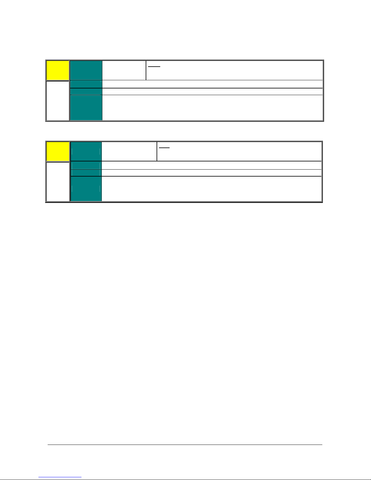
SINUS PENTA
The actual range depends on the max. value and the min. value of
et in
but multiplied
PID
). As for the display/keypad, the unit of measure can be
The actual range depends on the max. value and the min. value
and on the gain
zone mode as
). As for the display/keypad, the unit of measure can be
M024 PID Feedback
M024
M024a PID2 Feedback
M024a
Range 32000
Active
Address
Function
Range 32000
Active This measure is active if enabled from C291a
Address
Function
PROGRAMMING
INSTRUCTIONS
Note:
the PID feedback set in parameters P247–P248 and on the gain level s
P257.
Always active.
1674
This is the measure of the feedback being used for the PID regulator, as M020
by the gain level set in P257 (see also the PID PARAMETERS MENU and the
CONFIGURATION MENU
programmed with parameters P267, P267a in the DISPLAY/KEYPAD menu.
Note:
of the PID2 feedback set in parameters P447–P448
level set in P457.
1738
This is the measure of the feedback being used for the PID2 regulator or the 2M020a but multiplied by the gain level set in P457 (see also the PID2 PARAMETERS MENU
and the PID CONFIGURATION MENU
programmed with parameters P267b, P267c in the DISPLAY/KEYPAD menu.
56/452
Page 57
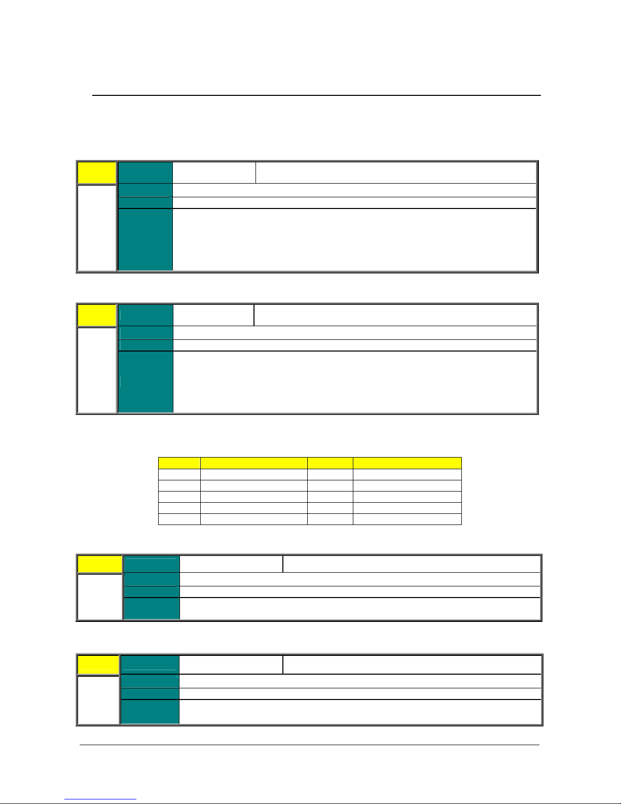
PROGRAMMING
of the virtual control terminal board used by the drive. This is the terminal board
resulting from the combination of the preset command sources (local terminal board, serial
commands. For the other inputs, the OR command between the different
TIMERS
State of the virtual control terminal board before applying the timers to the digital inputs (if
er is applied, it matches with M031). This is the terminal board resulting from the
combination of the preset command sources (local terminal board, serial link and fieldbus),
or
the other inputs, the OR command between the different command sources is used. See
INSTRUCTIONS
SINUS PENTA
8.4. Digital Inputs Menu
This menu allows checking the state of the command sources for the digital inputs (local terminals, serial link and
fieldbus), the terminal board resulting from their combination and the terminals which are actually used for the drive
control. The terminals which are actually used to control the drive also consider any timers applied to the digital inputs.
M031 Delayed Digital Inputs
M031
M032 Instant Digital Inputs
M032
Range
Active
Address
Function
Range
Active
Address
Bit-controlled
measure
Always active.
1681
State
link and fieldbus), where the ENABLE command is given by the AND logic of all the
ENABLE
command sources is used. See also the CONTROL METHOD MENU and the
MENU.
Bit-controlled
measure
Always active.
1682
See Table 1
See Table 1
Function
M033 Local Control Terminal Board
M033 Range
Active
M034 Control Terminals from Serial Link
M034
Address
Function
Range
Active
Address
Function
no tim
where the ENABLE command is given by the AND logic of all the ENABLE commands. F
also the CONTROL METHOD MENU and the TIMERS MENU.
Table 1: Coding of Measures M031, M032.
Bit n. Digital Input Bit n. Digital Input
0 MDI1(START) 5 MDI6/ECHA/FINA
1 MDI2(ENABLE) 6 MDI7/ECHB
2 MDI3(RESET) 7 MDI8/FINB
3 MDI4 8 ENABLE S
4 MDI5 9 ENABLE
Bit-controlled measure See Table 2
Always active.
1683
State of the digital inputs in the drive terminal board.
Bit-controlled measure See Table 2
Always active.
1684
State of the digital inputs in the terminal board controlled via serial link.
57/452
Page 58
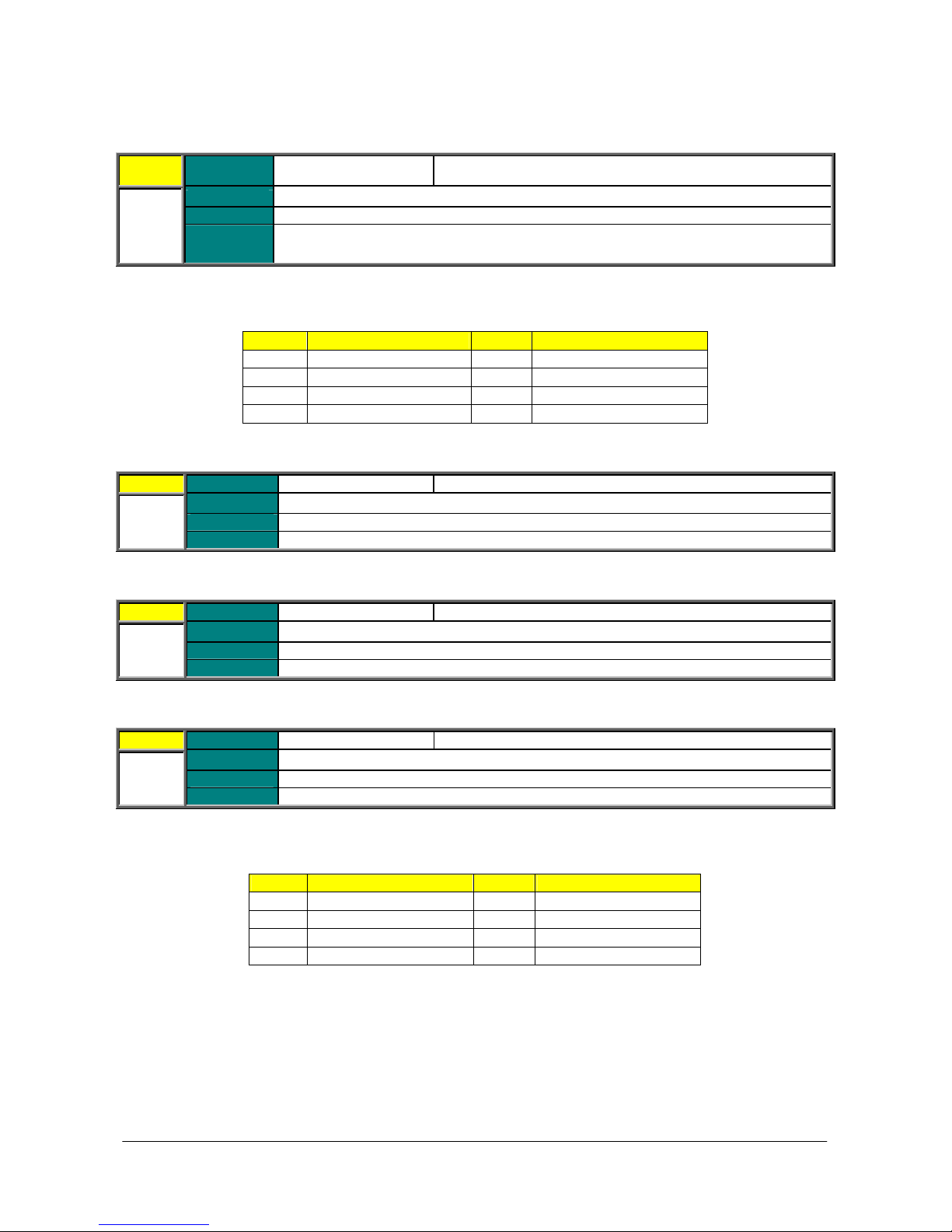
SINUS PENTA
M035 Control Terminal Board from Fieldbus
M035
Range
Bit-controlled measure See Table 2
PROGRAMMING
INSTRUCTIONS
Active
M036 Auxiliary Digital Inputs in the Terminal Board
M036 Range Bit-controlled measure See Table 3
M036a Auxiliary Digital Inputs via Serial Link
M36a Range Bit-controlled measure See Table 3
M036b Auxiliary Digital Inputs via PROFIdrive
M036b
Address
Function
Active
Address
Function
Active
Address
Function
Range
Active
Address
Function
Always active.
1685
State of the digital inputs in the terminal board controlled from fieldbus.
Table 2: Coding of Measures M033, M034, M035.
Bit n. Digital Input Bit n.
0 MDI1(START) 4 MDI5
1 MDI2(ENABLE) 5 MDI6/ECHA/FINA
2 MDI3(RESET) 6 MDI7/ECHB
3 MDI4 7 MDI8/FINB
Always active.
1686
State of the 8 auxiliary digital inputs in ES847 or ES870 terminal board.
Always active.
1713
State of the 8 auxiliary digital inputs via serial link.
Bit-controlled measure See Table 3
Always active.
1717
State of the 8 auxiliary digital inputs via PROFIdrive.
Table 3: Coding of Measures M036, M036a, M036b.
Bit n.
0 XMDI1 4 XMDI5
1 XMDI2
2 XMDI3 6 XMDI7
3 XMDI4 7 XMDI8
Digital Input Bit n.
Digital Input
Digital Input
5
XMDI6
58/452
Page 59
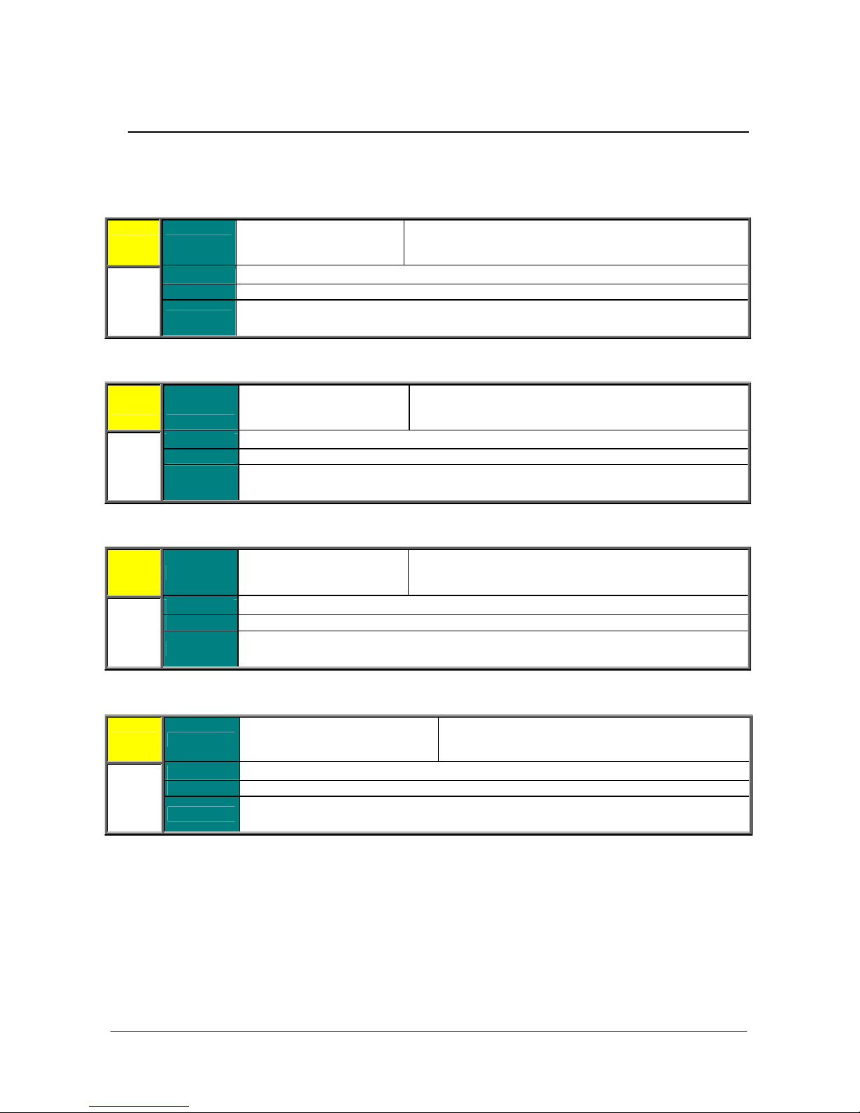
PROGRAMMING
.
two decimal figures; the
Function of the type of reference (voltage/current) set in
. The numerical value always includes two decimal
.
l value always includes two decimals; the unit of
.
The numerical value always includes two decimals; the
INSTRUCTIONS
SINUS PENTA
8.5. References Menu
This menu contains the measures of the possible reference sources for speed, torque or PID available in the terminal
board (analog inputs, frequency inputs and encoder input) and sent via serial link or fieldbus.
M037 REF External Analog Reference
M037
M038 AIN1 External Analog Reference
Range
Active
Address
Function
Function of the preset type of
reference (voltage/current).
Always active.
1687
Measure of the voltage /current value detected by the drive in REF analog input.
Function of the type of reference (voltage/current) set in P050
The numerical value always includes
unit of measure is V or mA.
M038
M039 AIN2 External Analog Reference
M039
M039a XAIN4 External Analog Reference
M039a
Range
Active
Address
Function
Range
Active
Address
Function
Range
Active Active only if set via parameter R023.
Address
Function
Function of the preset type of
reference (voltage/current)
Always active.
1688
Measure of the voltage /current value detected by the drive in AIN1 analog input.
Function of the preset type of
reference (voltage/current).
Always active.
1689
Measure of the voltage /current value detected by the drive in AIN2 analog input.
Function of the preset type of
reference.
1729
Measure of the voltage value detected by the drive in XAIN4 analog input.
P055
figures; the unit of measure is V or mA.
Function of the type of reference (voltage/current) set in P060
The numerica
measure is V or mA.
Function of the type of reference (voltage) set in P390
unit of measure is V.
59/452
Page 60
SINUS PENTA
.
two decimals; the
The actual range depends on the selected motor, because it is defined
by the value set in the parameters for the max. speed and min. speed of the
The actual range depends on the selected motor, because it is defined by
the value set in the parameters for the max. speed and min. speed of the
ue set for the selected
This is the measure of the torque reference set via serial link and expressed as a percentage
M039b XAIN5 External Analog Reference
M039b
M040 Speed Reference from Serial Link
M040 Range
Range
Active Active only if set via parameter R023.
Address
Function
Active
Address
Function This is the value of the speed reference set via serial link.
Function of the preset type of
reference.
1730
Measure of the current value detected by the drive in the XAIN5 analog input.
32000.99 rpm
32000
(integer part)
99
(decimal part)
Always active.
1690 (integer part), 1691 (decimal part)
Note:
selected motor.
C028–C029 Motor 1
C072–C073 Motor 2
C114–C115 Motor 3
PROGRAMMING
INSTRUCTIONS
Function of the type of reference (current) set in P395
The numerical value always includes
unit of measure is mA.
M042 Speed Reference from Fieldbus
32000
(integer
M042 Range
Active
M044 Torque Reference from Serial Link
M044 Range 5000
Address
Function
Active
Address
Function
part)
99
(decimal
part)
Always active.
1692 (integer part), 1693 (decimal part)
This is the measure of the speed reference set by the fieldbus.
Always active.
1694
of the rated torque of the selected motor.
32000.99 rpm
Note:
selected motor.
C028–C029 Motor 1
C072–C073 Motor 2
C114–C115 Motor 3
500.0 %
Note: The actual range depends on the torque limit val
motor.
C047–C048 Motor 1
C090–C091 Motor 2
C133–C134 Motor 3
60/452
Page 61
PROGRAMMING
The actual range depends on the torque limit values set for the selected
This is the measure of the torque reference set by the fieldbus and expressed as a percentage
n the min. value and the max. value of the PID
The actual range depends on the min. value and the max. value of the
The actual range depends on the min. value and the max. value of the
INSTRUCTIONS
M045 Torque Reference from Fieldbus
500.0 %
Note:
M045 Range
Active
M046 PID Reference from Serial Link
M046 Range
Address
Function
Active
Address
Function This is the measure of the PID reference set via serial link and expressed as a percentage.
5000
Always active.
1695
of the rated torque of the selected motor.
10000
Always active.
1696
motor.
C047–C048 Motor 1
C090–C091 Motor 2
C133–C134 Motor 3
100.00 %
Note: The actual range depends o
reference set in parameters:
P245–P246
SINUS PENTA
M047 PID Reference from Fieldbus
M047 Range
Active
M048 PID Feedback from Serial Link
M048
Address
Function
Range
Active Always active.
Address 1698
Function
10000
Always active.
1697
This is the measure of the PID reference set by the fieldbus and expressed as a percentage.
10000
This is the measure of the PID feedback set via serial link and expressed as a percentage.
100.00 %
Note:
PID reference set in parameters:
P245–P246
100.00 %
Note:
PID feedback set in parameters:
P247–P248
61/452
Page 62
SINUS PENTA
The actual range depends on the min. value and the max. value of the
ENCODER/FREQUENCY INPUTS
The actual range depends on the frequency min. value
source (see the
M049 PID Feedback from Fieldbus
M049 Range
Active
M050 Encoder Reference
M050 Range
M051 Frequency Input Reference
M051 Range
Address
Function
Active
Address
Function
Active Always active.
Address 1701
Function
10000
Always active.
1699
This is the measure of the PID feedback set by the fieldbus and expressed as a percentage.
32000 32000 rpm.
Always active.
1700
Reading of the encoder set as a reference source (see the
MENU and the CONTROL METHOD MENU).
1000 10000
Frequency readout in the digital input set as a reference
ENCODER/FREQUENCY INPUTS MENU and the CONTROL METHOD MENU).
100.00 %
Note:
PID feedback set in parameters:
P247–P248
10000 100000 Hz.
Note:
and max. value set in P071-P072.
PROGRAMMING
INSTRUCTIONS
62/452
Page 63
PROGRAMMING
INSTRUCTIONS
SINUS PENTA
8.6. Outputs Menu
This menu allows checking the status of the digital outputs, the analog outputs and the frequency outputs located in the
terminal board.
M056 Digital Outputs
M056
M056a Virtual Digital Outputs
M056a Range
Range
Active
Address
Function
Active
Address
Function
Bit-controlled measure. See Table 4
Always active.
1706
Status of digital outputs MDO14 and status of the precharge contactor.
Table 4: Coding of Measure M056.
Bit n. Digital Output
0 MDO1/FOUT
1 MDO2
2 MDO3
3 MDO4
6
Bit-controlled measure. See Table 5
Always active.
1675
Status of virtual digital outputs MPL14.
Status of the precharge
contactor
M056b Timed Flags
M056b Range
Active
Address
Function Status of timed flags TFL1 4.
Table 5: Coding of Measure M056a.
Bit n.
0 MPL1
1 MPL2
2 MPL3
3 MPL4
Bit-controlled measure See Table 6
Always active.
1741
Table 6: Coding of Measure M056b.
Bit n.
0 TFL1
1 TFL2
2 TFL3
3 TFL4
Digital Output
Timed Flag
63/452
Page 64
SINUS PENTA
: The actual range depends on the min. value and the max. value of
This is the frequency measure produced by MDO1 digital output when set as a frequency
Value percent of analog output AO1, referred to the preset max. output value (maximum
FREQUENCY OUTPUTS
Value percent of AO2 analog output referred to the preset max. output value (maximum
FREQUENCY OUTPUTS
max. output value (maximum
FREQUENCY OUTPUTS
M057 Frequency Output
M057
M058 AO1 Analog Output
M058
M059 AO2 Analog Output
M059
M060 Analog Output AO3
M060
M061 Auxiliary Digital Outputs
M061
Range
Active
Address
Function
Range
Active
Address
Function
Range
Active
Address
Function
Range
Active
Address
Function
Range
Active
Address
Function
10000100000
Always active.
1707
output.
100 100 %
Always active.
1708
absolute value between P182 and P183, see ANALOG AND
MENU).
100 100 %
Always active.
1709
absolute value between P190 and P191, see ANALOG AND
MENU).
100 100 %
Always active.
1710
Value percent of AO3 analog output referred to the preset
absolute value between P198 and P199, see ANALOG AND
MENU).
Bit-controlled measure. See Table 7
Always active.
1711
Status of the auxiliary digital outputs located on the expansion board.
PROGRAMMING
INSTRUCTIONS
10000 100000 Hz
Note
MDO1 digital output set as a frequency reference. Values are set in P204
and P205 (see ANALOG AND FREQUENCY OUTPUTS MENU).
Table 7: Coding of Measure M061.
Bit n.
0 XMDO1 3 XMDO4
1 XMDO2 4 XMDO5
2 XMDO3 5 XMDO6
Digital Output Bit n.
64/452
Digital Output
Page 65
PROGRAMMING
INSTRUCTIONS
SINUS PENTA
8.7. Temperature Measures from PT100 Menu
This menu displays the temperatures detected in the first four analog channels of the expansion board.
Scaling complies with DIN EN 60751 for PT100: 100 ohm @ 0 °C and 0.385 ohm/°C.
ES847 Expansion Board must be fitted on the equipment.
See also the EXPANSION BOARD CONFIGURATION MENU
M069 PT100 Measure in Channel 1
M069 Range
Active This measure is active only if programmed from parameter R023.
M070 PT100 Measure in Channel 2
M070 Range –500 ÷2600 –50.0 ÷260.0 °C
Address 1719
Function
Active This measure is active only if programmed from parameter R023.
Address
Function
–500 ÷2600 –50.0 ÷260.0 °C
Temperature detected in analog channel 1.
1720
Temperature detected in analog channel 2.
M071 PT100 Measure in Channel 3
M071 Range
Active This measure is active only if programmed from parameter R023.
Address
Function
–500 ÷2600 –50.0 ÷260.0 °C
1721
Temperature detected in analog channel 3.
M072 PT100 Measure in Channel 4
M072 Range
Active This measure is active only if programmed from parameter R023.
Address
Function
–500 ÷2600 –50.0 ÷260.0 °C
1722
Temperature detected in analog channel 4.
65/452
Page 66
SINUS PENTA
bit words: the low part and the high
M
O
M
PRODUCT
ure is forced to 32,000, corresponding to
PROGRAMMING
INSTRUCTIONS
8.8. Autodiagnostics Menu
This menu allows the user to check the functioning times and the relevant counters (for maintenance purposes) of the
Penta drive; it also allows reading out the analog channels used for temperature sensors and the relevant temperature
values, as well as the drive status.
M052 / M054 Functioning Times
M052 /
M054
Functioning Times:
M062 Ambient temperature Measure
M062
Range
Address
Function
Range
Active
Address
Function
0 ÷ 2147483647 (0 ÷ 7FFFFFFFh) 0 ÷429496729.4 sec
Supply Time: 1702-1703 (LSWord, MSWord)
Operation Time: 1704-1705 (LSWord, MSWord)
This screen displays the ST (supply time) and the OT (operation time).
The Operation Time is the activation time of the drive IGBTs.
Both values are expressed in 32 bits divided into two 16part.
S u p p l y T i m e
0 5 4 = 5 3 : 2 5 : 0 1
p e r a t i o n T i m e
0 5 2 = 2 9 : 3 5 : 5 1
32000 320.0 °C
Always active.
1712
Ambient temperature measured on the surface of the control board.
M064 IGBT Temperature Measure
M064
Range
Active
Address
Function
32000 320.0 °C
Always active.
1714
Measure of the IGBT temperature.
If the temperature readout is <–30.0 °C or >150.0 °C, warning W50 – NTC Fault appears.
Note: Not all models are provided with the NTC sensor (see Table 13 in the
MENU). If this sensor is not provided, the meas
+320.0 °C.
66/452
Page 67
PROGRAMMING
Operation Time is the
INSTRUCTIONS
M065 Operation Time Counter
M065 Range
Active
M066 Supply Time Counter
M066 Range
M089 Drive Status
M089 Range
Address
Function
Active
Address
Function
Active
Address
Function
0÷65000 0÷650000h
Always active.
1715
Time elapsed after resetting the operation time counter. The
activation time of the drive IGBTs.
0÷65000 0÷650000h
Always active.
1716
Time elapsed after resetting the supply time counter.
See Table 125.
Always active.
1739
Describes the current condition of the Penta drive.
SINUS PENTA
M090 Active Alarm
M090 Range
Active
Address
Function
See Table 122.
Always active.
1740
Alarm tripped at the moment.
67/452
Page 68
SINUS PENTA
To program ES851, a connection to a computer via the RemoteDrive software is required,
ES851 is ready to be configured even through the display/keypad of the
This indicates a general alarm tripped for ES851. In case an alarm trips, please contact
PROGRAMMING
INSTRUCTIONS
8.9. Data Logger Measures Menu
This menu displays the status of the types of connections (serial links, Ethernet and modem) supported by ES851 Data
Logger board.
This menu can be viewed only if the Data Logger board is fitted.
See also the DATA LOGGER MENU.
M100 Data Logger Status (Line 3)
M100
Line 3
M100 ES851 Fault (Line 4)
M100
Line 4
Range 0 2
Active This measure is active only if programmed from parameter R021.
Address
Function
Range 0 6, 99 104
Active This measure is active only if programmed from parameter R021.
Address
Function
1336
0: NOT FITTED, ES851 is not installed on the Penta drive.
1: OK not interlocked, ES851 is operating independently of the drive where it is installed.
or a special preset set via display/keypad is required (see the DATA LOGGER MENU).
2: OK interlocked,
drive where it is installed.
1340
BCH ELECTRIC LTD’s CUSTOMER SERVICE and mention the alarm code and name.
0: NOT FITTED
1: OK not interlocked
2: OK interlocked
0: No alarm
1: Parameter save fault
2: Log write error
3: FBS configuration failure
4: RS232 Modbus configuration failure
5: RS485 Modbus configuration failure
6: TCP/IP stack configuration failure
99: Flash card lacking or inaccessible
100: Invalid stream access
101: TCP/IP socket fault
102: Dial out connection failure
103: Control board clock failure
104: Modem initialization failure
68/452
Page 69
PROGRAMMING
Status of the connections supported by ES851. Note that the COM1 serial link is RS232 by
INSTRUCTIONS
SINUS PENTA
M101 Connection Status
M101 Range
Active This measure is active only if programmed from parameter R021.
Address
Function
Bit n. Connection Description
0-7 Type of modem connection failure 0: None
8-10 Status of the connection via modem 0: No conn.
11 COM1 0: No data exchange
12 COM2 0: No data exchange
13 Ethernet 0: No connection
14-15 Reserved
* In computer networking, the Internet Protocol Control Protocol (IPCP) is a network control protocol for establishing
and configuring Internet Protocol over a Point-to-Point Protocol link. The IPCP configures, enables, and disables the IP
protocol modules on both ends of the point-to-point link.
Bit-controlled measure See Table 8
1338
default, whereas COM 2 is RS485 by default.
For more details, please refer to the Programming Instructions manual for the Data Logger
ES851.
Table 8: Data Logger connection status.
1: Dial KO
2: Connect KO
3: Authentication KO
4: IPCP KO*
5: Modem not yet initialized
6: Modem init KO
7: Modem not configured
8: Modem not dial out
16: Connect end (echo time out)
32: Connect end (idle time out)
64: Connect end (term expired)
1: Dialing
2: Connecting
4: Connected
5: Attempt finished
1: Data exchanged
1: Data exchanged
1: Connection
69/452
Page 70

SINUS PENTA
8.10. Digital Input Settings Menu
This menu allows checking the functions assigned to the digital inputs.
Table 9: Coding of the functions assigned to the digital inputs.
Displayed Items Function Assigned to the Digital Inputs
STOP Stop function
REVERSE Startup with negative speed
EN–S ENABLE in safety condition
DISABLE Drive disable
MVel0 Multispeed 0
MVel1 Multispeed 1
MVel2 Multispeed 2
MVel3 Multispeed 3
Cw/CCw Reversal of the direction of rotation
DCB DC braking
UP Reference increase
DOWN Reference decrease
UDReset Reset of speed setpoint due to UP/DOWN command
Alarm 1 Auxiliary trip 1
Alarm 2 Auxiliary trip 2
Alarm 3 Auxiliary trip 3
MRmp0 Multiramp 0
MRmp1 Multiramp 1
JOG Jog mode
SLAVE Selection of Slave Mode
PID Dis PID Disable
KpdLock Display/keypad unit
Mot 2 Selection of Motor 2
Mot 3 Selection of Motor 3
Var 0 Reference Variation 0
Var 1 Reference Variation 1
Var 2 Reference Variation 2
PID UDR PID Reference Reset due to UP/DOWN commands
LOCAL Selection of Local mode
Brk Lock Mechanical brake locking
FireM Fire Mode enabled
Src. Sel Reference/command source switch
nTlim External torque limit disable
START_B START function, terminals B
STOP_B STOP function, terminals B
REVERSE_B Startup with negative speed, terminals B
MRef0 PID Multireference 1
MRef1 PID Multireference 2
MRef2 PID Multireference 3
PID Csl PID Control Selection
START START function
ENABLE ENABLE function
RESET Alarm RESET
EncA Encoder A Input
EncB Encoder B Input
FinA FINA Frequency input
FinB FINB Frequency input
Multi More than one function allocated to the same input
PROGRAMMING
INSTRUCTIONS
70/452
Page 71
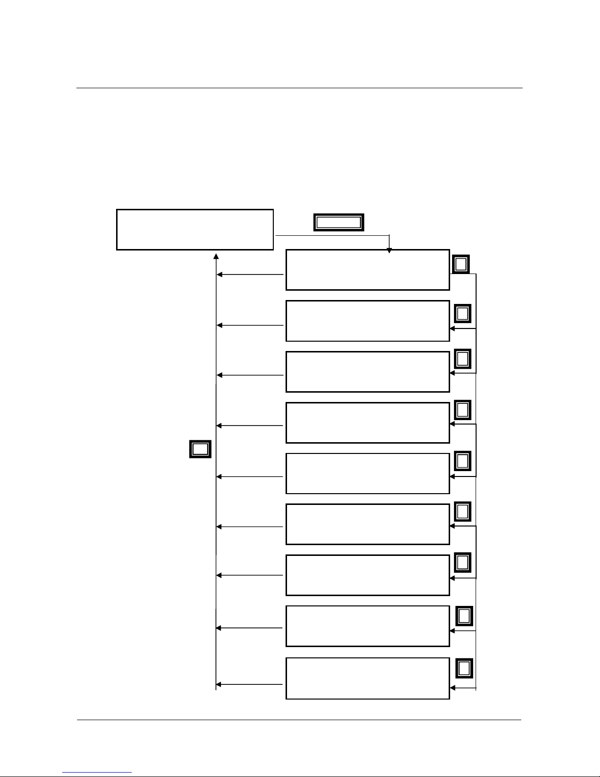
PROGRAMMING
A 0 8 0 S P E E D
T
O T
M 0 0 2
M 0 0 4
M 0 0 8
M 0 0 9
M 0 2 9
M 0 3 0
M 0 6 4
M 0 0 6
M 0 2 6
D i g i t a l
M 0 3 1
M 0 2 8
WD i g i t a l
M 0 5 6
M 0 5 8
M 0 5 9
M 0 6 0
M 0 6 2
INSTRUCTIONS
SINUS PENTA
8.11. Fault List Menu
Scroll the Fault List Menu to display the codes of the last eight alarms tripped.
Press the SAVE/ENTER key to access the alarm submenu and navigate to each value measured by the drive when the alarm
tripped.
The diagram below shows a navigation example for the Fault List Menu (relating to alarm n.1 in particular). Note that
n.1 is the last alarm tripped and n.8 is the first alarm tripped.
The measures marked with Mxxx are the same measures covered in this section.
If the Data Logger ES851 is installed (even the ES851 RTC version only) and parameter R021 Data Logger is set to 2:
ENABLE, the date and time when the alarm has tripped are displayed instead of the Supply Time (ST) and the
Operation Time (OT) respectively.
Navigation Example - Fault List Menu.
A l a r m
n . 1
T R A C K I N G
Esc
Save/Enter
A l a r m 1 M e a s u r e s
I n v e r t e r S t a t u s
C O N S T. R P M L I M I T
F O C
M O T O R 1
A l a r m 1 M e a s u r e s
r i p T i m e
S T
9 2 : 1 6 : 1 8
4 5 : 2 0 : 1 2
A l a r m 1 M e a s u r e s
+
+
1 4 5 2 r p m
+
4 5 0 r p m
5 5 . 2 N m
A l a r m 1 M e a s u r e s
+
5 5 . 4 N m
5 5 1
3 9 4
V
d c
V
a c
A l a r m 1 M e a s u r e s
+
+
+
3 2 . 4 ° C
0 . 0 H z
1 5 . 2
A l a r m 1 M e a s u r e s
I n p u t s
E
E s 1 2 3 4 5 6 7 8
■
■
■ ■ □ □ □ □ □ □
A l a r m 1 M e a s u r e s
+
8 . 5
k
I n p u t s
1 □
2 □
3 ■
4 ■
A l a r m 1 M e a s u r e s
( A O 1 ) –
( A O 2 ) +
( A O 3 ) –
8 5 %
3 5 %
1 0 %
A l a r m 1 M e a s u r e s
+
2 7 . 0 ° C
A
71/452
Page 72
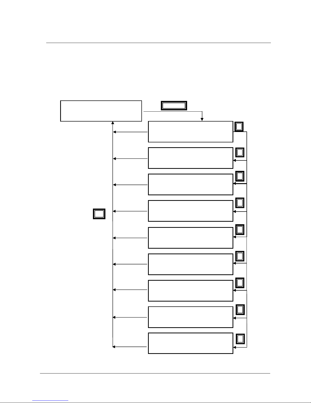
SINUS PENTA
T
O T
M 0 0 2
M 0 0 4
M 0 0 8
M 0 0 9
M 0 2 9
M 0 3 0
M 0 6 4
M 0 0 6
M 0 2 6
D
M 0 3 1
M 0 2 8
WD i g i t a l
M 0 5 8
M 0 5 9
M 0 6 0
M 0 6 2
▲ ▲ ▲ ▲ ▲ ▲ ▲ ▲ ▲
PROGRAMMING
INSTRUCTIONS
8.12. Power Off List Menu
This menu contains the measures of some characteristic variables detected at the drive power off, in conjunction with
the alarm (if any) tripped at that moment.
Press the SAVE/ENTER key to access the submenu and navigate to the measures detected by the drive when the
alarm tripped. Measures and codes are the same as the ones shown in the Fault List Menu.
If the Data Logger ES851 is installed (even the ES851 RTC version only) and parameter R021 Data Logger is set to 2:
ENABLE, the date and time when the alarm has tripped are displayed instead of the Supply Time (ST) and the
Operation Time (OT) respectively.
The diagram below shows a navigation example for the Power Off List.
Navigation Example – PowerOff List Menu
A l a r m a t
P o w e r O f f
Save/Enter
A l a r m N u m b e r 0 0 0
I n v e r t e r O F F
I n v e r t e r S t a t u s
M e a
C O N S T. R P M L I M I T
F O C
M O T O R E
I n v e r t e r O F F
2
M e a
r i p T i m e
Esc
S T
I n v e r t e r O F F
I n v e r t e r O F F
+
I n v e r t e r O F F
I n v e r t e r O F F
i g i t a l I n p u t s
E
■
I n v e r t e r O F F
M 0 5 6
1 □
I n v e r t e r O F F
( A O 1 ) =
( A O 2 ) =
( A O 3 ) =
I n v e r t e r O F F
9 5 : 2 0 : 1 2
4 5 : 2 0 : 1 2
+
1 4 5 2 r p m
+
+
4 5 0 r p M
5 5 . 3 N M
5 5 . 4 N m
5 5 1
3 9 4
+
+
+
E s 1 2 3 4 5 6 7 8
■
+
3 2 . 4 ° C
1 5 . 2
■ ■ □ □ □ □ □ □
8 . 5
M e a
M e a
V
V
M e a
0 . 0 H z
M e a
M e a
O u t p u t s
+
2 □
2 7 . 0 ° C
3 ■
–
+
–
M e a
8 5 %
3 5 %
1 0 %
M e a
d c
a c
k
4 ■
A
9. PRODUCT MENU
72/452
Page 73
PROGRAMMING
to choose a
The software implemented in the display/keypad is called MMI (man/machine
INSTRUCTIONS
SINUS PENTA
9.1. Overview
The Product Menu includes parameter P263 Language, allowing the user to select a dialog language; it also contains
the Fire Mode enabling Password and the following information (read-only) about the product:
Product Name and Type
Implemented Software
SW Versions
Serial Number
Manufacturer
9.2. List of Parameter P263 and Fire Mode Enable Password
Table 10: List of parameter P263 and Fire Mode Enable Password.
Parameter
P263
P263 Language
P263 Range 0 4
Default
Level
Address
Function
FUNCTION
Language BASIC 1:ENGLISH 863
Fire Mode Enable Password BASIC 0 868
0: ITALIANO
1: ENGLISH
2: ESPANOL
3: PORTUGUES
4: DEUTSCH
1 1: ENGLISH
BASIC
863
The dialog language is factory set to English. Use parameter P263
different language.
interface); its version is displayed in the SW screen of the Product Menu.
User
Level
DEFAULT VALUE
MODBUS
Address
CAUTION
By request, BCH ELECTRIC LTD can provide the extended version of the MMI
software containing languages different from the ones mentioned above.
73/452
Page 74
SINUS PENTA
PROGRAMMING
INSTRUCTIONS
Product Name and Type
Product Name
and Type Range
Address
Function
Fan control: bits 0 to 3
Voltage class: bits 4 to 7
Drive size: bits 8 to 15
0 ÷ 3 – see Table 16
0 ÷ 3 – see Table 12
0 ÷ 81 – see Table 11
Type: 1593
This screen displays the name of the product (PENTA) and the type of product (see
example below).
P r o d u c t N a m e
P E N T A
T y p e 0 0 2 0 4 T _
The product name (PENTA) appears in the second line of the display/keypad. The third line shows the voltage class,
the size of the drive and the type of fan control.
In the case shown in the example, the voltage class is 4T (400V), the size of the drive is 0020 and the fan operation is
not controlled by the drive (character _ ).
The numbers corresponding to the different models of the Penta Drive are given in the table below:
Table 11: Indexes corresponding to the different models (sizes) of the Penta Drive.
Index Model Index Model Index Model Index Model Index Model
0
1
2
3
4
5
6
7
8
9
10
11
12
13
14
15
16
17
18
19
0003
0004
0005
0006
0007
0008
0009
0010
0011
0012
0013
0014
0015
0016
0017
0018
0019
0020
0021
0022
20
21
22
23
24
25
26
27
28
29
30
31
32
33
34
35
36
37
38
39
0023
0024
0025
0030
0032
0033
0034
0035
0036
0037
0038
0040
0042
0049
0051
0060
0062
0067
0069
0074
40
41
42
43
44
45
46
47
48
49
50
51
52
53
54
55
56
57
58
59
0076
0086
0088
0113
0129
0131
0150
0162
0164
0172
0179
0180
0181
0200
0201
0202
0216
0217
0218
0250
60
61
62
63
64
65
66
67
68
69
70
71
72
73
74
75
76
77
78
79
0259
0260
0290
0312
0313
0314
0366
0367
0368
0399
0401
0402
0457
0459
0523
0524
0526
0598
0599
0600
80
81
82
83
84
85
86
87
88
89
90
91
92
93
94
95
96
0748
0749
0750
0800
0828
0831
0832
0850
0960
0964
0965
1128
1129
1130
1296
1800
2076
Table 12: Voltage classes of the PD.
Index Class
0
1
2
3
2T
4T
5T
6T
74/452
Page 75
PROGRAMMING
This screen displays the type of software application which is implemented in the
User
This is the serial number of the drive. The serial number is required when
CUSTOMER SERVICE in order to activate the
t
INSTRUCTIONS
The type of fan control is marked by 3 characters:
Table 13: Fan control modes.
Character
The fan activation is controlled by the inverter.
F
The fan operation is correct: when a fan fault is detected, the relevant alarm trips.
S
A NTC sensor is fitted, that acquires the heatsink temperature. The fan activation threshold is set
N
in parameter C264.
Table 14: Coding for fan activation
SW Application
SW Application
Code
0
1
2 F-- Yes No No
3
4
5
6
7
Function
Symbol Fan control Fan status
---
-S-
FS-
--N
-SN
F-N
FSN
drive (e.g. Multipump, Regenerative, etc...).
See BCH ELECTRIC LTD’s Catalogue about Software Accessories.
For the application software downloading instructions see the relevant
Manuals.
SINUS PENTA
Description
NTC
No No No
No Yes No
Yes Yes No
No No Yes
No Yes Yes
Yes No Yes
Yes Yes Yes
User SW Versions
SW Versions Range
Address
Function
Serial Number
Serial Number
Range 0 9999999 0 9999999
Address
Function
0 65535 0 65.535
Texas: 233
MMI: 1489
Motorola: 1487
This screen displays the SW versions implemented on the Penta drive:
Texas SW version of the DSP Texas
MMI SW version of the display/keypad
Motorola SW version of Motorola microprocessor
1827-1828 (LSWord, MSWord)
contacting BCH ELECTRIC LTD’s
Fire Mode.
This measure is expressed in 32 bits divided into two 16-bit words: the low par
and the high part.
75/452
Page 76
SINUS PENTA
CUSTOMER
ber of the drive where the Fire Mode is to be
You can read the product ID from address 476. The eight high bits give the first
Fire Mode Enable Password
Fire Mode
Enable
Password
Range 0 9999 0 9999
Default
Level
Address
Function
PROGRAMMING
INSTRUCTIONS
0 0
BASIC
868
To enable the Fire Mode, please contact BCH ELECTRIC LTD’s
SERVICE and give the Serial Num
activated. Enter the password given by the Customer Service.
CAUTION
Manufacturer
Manufacturer
You can also send a Modbus query message to read the product ID.
Product ID
Product ID Range
Function
Address
Function
The Fire Mode Enable Password is set to 0 when the Restore Default is performed.
The name of Conmpany
1 65535
476
character of the ID, the eight low bits give the second character of the product ID.
E.g. for PD (Penta Drive):
MODBUS value read from address 476: 20548d 0x5044H
50H Character ‘P’
44H Character ‘D’
76/452
Page 77
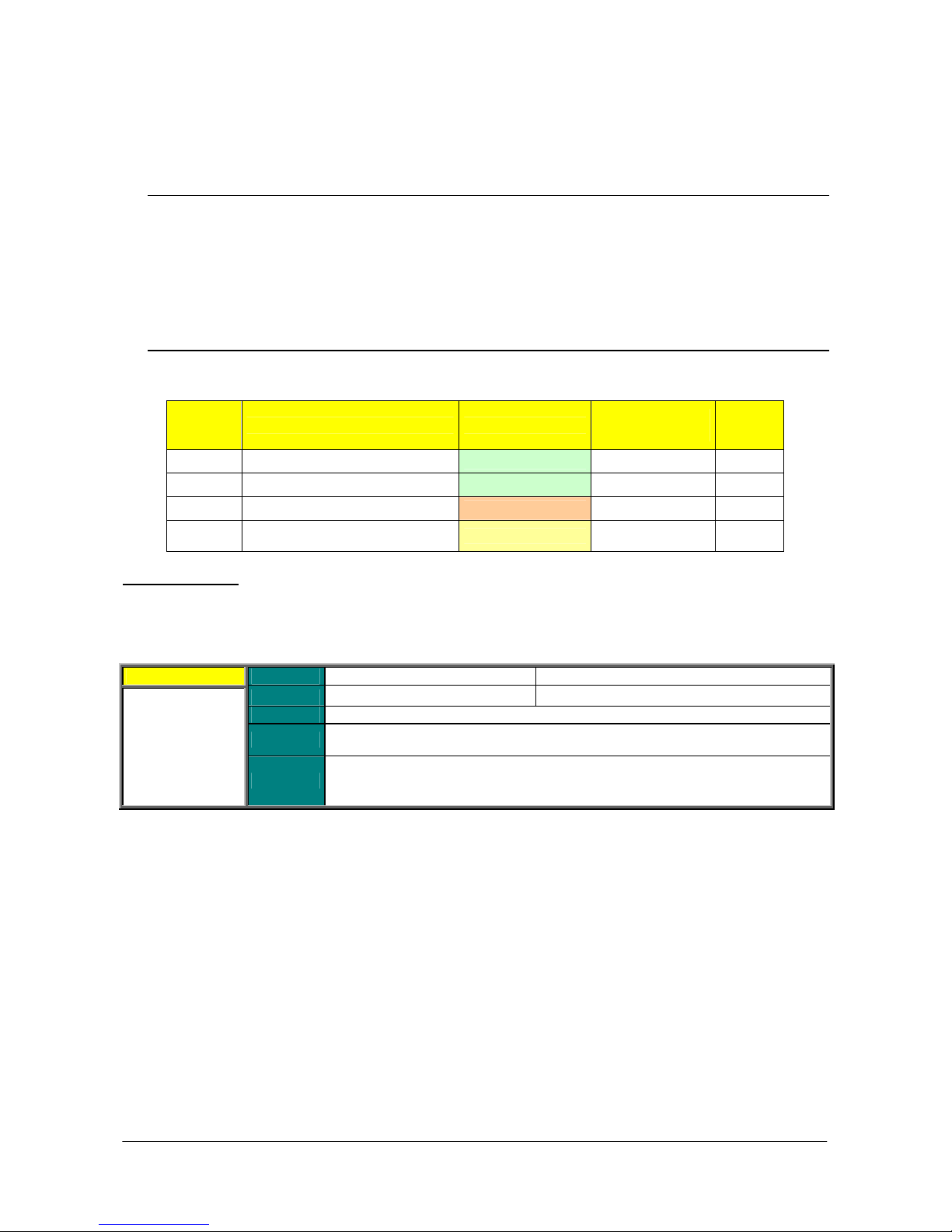
PROGRAMMING
INSTRUCTIONS
SINUS PENTA
10. PASSWORD AND USER LEVEL MENU
10.1. Overview
The Password and User Level menu allows changing the programming parameters and sets their visibility.
P000 enables parameter modification
P001 sets the user level
P002 allows to change the password set in P000
P003 conditions required to change C parameters
10.2. List of Parameters P000 to P003
Table 15: List of parameters P000 to P003.
Paramete
r
P000
P001
P002
P003
P000 Write Enable
Factory setting is P000 = 1 (parameter write is enabled). To access parameter P000 allowing parameter write, access
the Password and User Level Menu from the Parameters Menu.
P000 Range
Write enable BASIC 00001 513
Programming level
Write enable password ENGINEERING 00001 510
Conditions required to change C
parameters
Default
Level
Address
Function
FUNCTION User Level
BASIC
ADVANCED StandBy+Fluxing 509
00000÷32767 00000: [No] ÷32767
00001 00001
BASIC
Cannot be accessed via serial link.
Parameter write via serial link is always enabled.
Set the correct value in P000 to enable parameter write.
The default password for P000 is 00001.
You can enter a custom password in P002.
DEFAULT
VALUES
0:[Basic] 514
MODBU
S
Address
77/452
Page 78
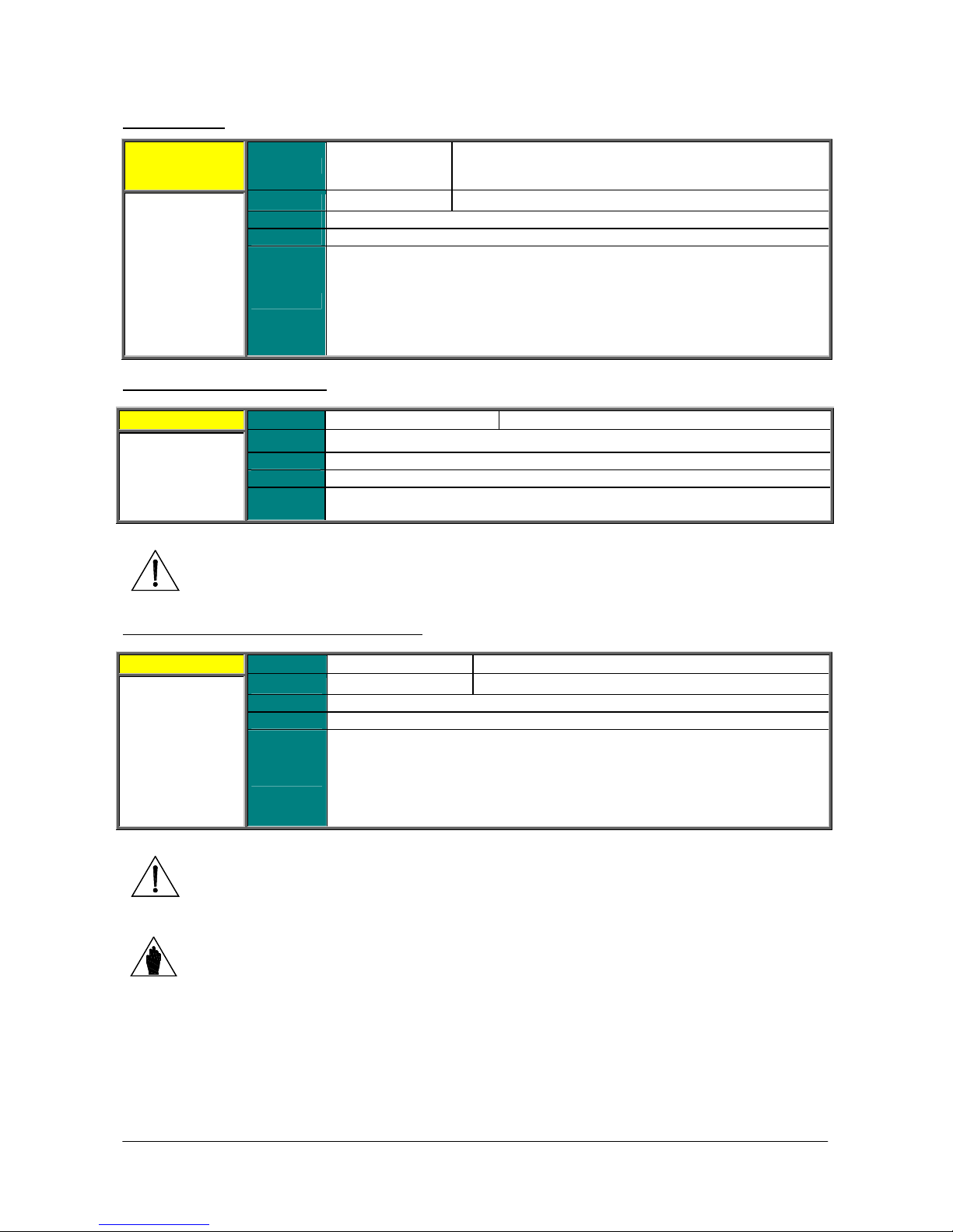
SINUS PENTA
The inverter programming parameters are grouped by access levels based on their
Some menus, or some parts of menus, are not displayed when a given access
s level is selected once the inverter parameterization is
, you can use
to be programmed even when the inverter is
C
and
motor selection: when those inputs change, they produce their effect only when C
P001 User Level
P001 Range
Default
Level
Address
0÷2
0 0 : Basic
BASIC
514
0: Basic
1: Advanced
2: Engineering
PROGRAMMING
INSTRUCTIONS
Function
P002 Password for Write Enable
P002 Range
Default 00001.
CAUTION
Level
Address
Function
functions (more or less complex functions).
level is selected.
When the BASIC acces
correct, navigation is easier, as only frequently accessed parameters are displayed.
The User Level is stated for each parameter.
00001 ÷ 32767 00001 ÷ 32767
ENGINEERING
510
Once write is enabled after entering the correct password in P000
parameter P002 to enter a custom password.
The new password allowing parameter write enable is the value entered in P002.
Note it down and keep it handy!
P003 Conditions for C Parameter Modifications
P003 Range
Default
Level
Address
Function
0 ÷ 1 0:[Stand-by only] ÷ 1:[StandBy+Fluxing]
1 1:[StandBy+Fluxing]
ADVANCED
509
Factory setting allows C parameters
enabled. However, the motor must be stopped. If P003=0: [Stand-by only],
parameters can be changed only when the inverter is disabled.
This parameter also affects the behaviour of the digital inputs for LOC/REM
parameters are allowed to be changed, according to the value in P003.
CAUTION
If P003 = 1:[StandBy+Fluxing] when changing a C parameter, the drive automatically
disables (stops modulating) and the motor starts idling.
NOTE
If C020 = 0: IFD [Voltage/Frequency], C parameters may be set up when the Enable input
is active and the motor is stopped independently of P003.
78/452
Page 79
PROGRAMMING
INSTRUCTIONS
11. DISPLAY/KEYPAD MENU
11.1. Overview
SINUS PENTA
NOTE
The Display/Keypad Menu contains programming parameters to do the following:
Set the navigation mode within the drive menus;
Select the Root Page;
Select measures from the Root Page and the Keypad Page;
Select the type of Keypad Page displayed in Local mode;
Set custom PID units of measure;
Disable the LOC/REM or FWD/REV keys in the keypad.
The Root Page, the Keypad Page and Local mode are detailed in the following sections.
It is recommended that the “Operating and Remoting the Keypad” section in the Sinus
Penta’s Installation Instructions Manual be read as well.
11.2. Root Page
I N V E R T E R O K
+ 1 5 0 0 . 0 0 r p m
+ 0 . 0 0 r p m
M E A P A R C F [ I D P ]
The Root page is factory-set as the startup page to be displayed when the drive is turned on.
NOTE
Line 1 on this page displays the drive operating status (see the description of parameter M089).
Lines 2 and 3 display two measures which may be selected with parameters P268, P268a. These measures can
be scaled through parameters P268y and P268z.
Line 4 displays the four main menus of the drive. The selected menu is displayed in square brackets: use the ▲ and ▼
keys to select a different menu. Press the SAVE/ENTER key to access the selected menu.
You can access the four main menus only from the root page:
MEA Measures;
PAR Programming parameters;
CF Configuration parameters;
IDP Product identification.
79/452
Page 80
SINUS PENTA
R e
M 0 0 6
M 0 2 6
M 0 0 4
PROGRAMMING
INSTRUCTIONS
11.3. Keypad Page and Local Mode
+ 0 . 0 H z
+ 0 . 0 A
+ 0 . 0 0 r p m
f + 1 5 0 0 . 0 0 r p m
To access the Keypad pages, press the MENU key from the Root Page or press the LOC/REM key after selecting the
Local mode.
The measures displayed on the Keypad page can be set up through parameters P268b to P268e. From the Keypad
page, press the SAVE/ENTER key to display the Keypad Help page, describing the measures displayed on the Keypad
page. The Keypad Help page is displayed for a few seconds.
If parameter P264b (Navigation mode via MENU key) is set to Operator, navigation is locked
NOTE
once the Keypad Page is displayed. Hold down the ESC key for a few seconds to resume
navigation.
R e f + 1 5 0 0 . 0 0 r p m
Keypad
Keypad Help
M o t . F r e q .
I ( R M S ) O u t
M o t o r S p d
SAVE/
ENTER
The following Keypad Pages are available:
Measures only four lines displaying measures only
Speed line 4 shows the speed reference, that can be changed with the ▲ and ▼ keys.
Torque line 4 shows the torque reference, that can be changed with the ▲ and ▼ keys.
Limit Torque line 4 shows the limit torque reference, that can be changed with the ▲ and ▼ keys.
PID line 4 shows the PID reference, that can be changed with the ▲ and ▼ keys.
If the Local Mode is NOT selected, pressing the MENU key allows viewing only the pages containing the references
sent via keypad (see the CONTROL METHOD MENU and the PID CONFIGURATION MENU).
LOCAL MODE
In LOCAL mode (the L-CMD and L-REF LEDs come on when the Local mode is active), only the commands and
references sent via keypad are enabled, while any other control source or reference source is disabled (see the
CONTROL METHOD MENU, the DIGITAL INPUTS MENU and the INPUTS FOR REFERENCES MENU). The keypad
page displayed when the LOC/REM key is pressed depends on the setting of parameter P266 (Type of Keypad Page in
Local Mode):
P266 = Measures Only Page containing 4 preset measures; no reference can be changed.
P266 = Ref.Activated Line 4 in the Keypad Page enables changing the drive reference: the speed reference if a
speed control is activated (“Ref” displayed), the torque reference if a torque control is activated (“TRef” displayed). If
the drive reference is the PID output (C294 PID Action = 1:[Reference]), the PID reference is given (“PRef” displayed).
Use the ▲ and ▼ keys to change the reference displayed in line 4 on the Keypad Page.
P266 = Ref.Activated+Spd To be used only when the drive reference depends on the PID output when a speed
control is used (C294 PID Action = 1:[Reference]). When the LOC/REM key is pressed for the first time, “PRef” is
displayed in line 4 and the PID reference may be adjusted; when the LOC/REM key is pressed twice, the PID is
disabled and the speed reference can be changed (“Ref” displayed).
Use the▲ and ▼ keys to change the reference shown in line 4 on the Keypad Page.
80/452
Page 81
PROGRAMMING
set and is activated whenever the Penta drive is
to navigate only through the parameters whose
mes active: only the parameters that have been
keys to go to a different
If
Linear navigation is selected, parameters are no longer divided into menus and
INSTRUCTIONS
SINUS PENTA
11.4. List of Parameters P264 to P269
Table 16: List of parameters P264 to P269.
Parameter
P264
P264a
P264b Navigation mode with the MENU key
P265
P266
P267
P267a
P267b
P267c Custom PID2 units of measure ENGINEERING [%] 1869
P268
P268y
P268a
P268z
P268b
P268c
P268d
P268e
P269 Disable LOC/REM FWD/REV keys
P264 Navigation Mode
Navigation mode ADVANCED 0 :[BY MENU] 864
Circular navigation ADVANCED 1: [YES] 865
Root page ADVANCED 3: [Start Up] 866
Type of Keypad page in Local Mode ADVANCED 1:[Ref.Activated] 511
Preset PID units of measure ENGINEERING 0:[Disable] 867
Custom PID units of measure ENGINEERING [%] 1867
Preset PID2 units of measure ENGINEERING 0:[Disable] 861
Measure n.1 on Root page ADVANCED
Scaling of Measure n.1 on Root page ADVANCED 100.00% 515
Measure n.2 on Root page ADVANCED
Scaling of Measure n.2 on Root page ADVANCED 100.00% 516
Measure n.1 on Keypad page ADVANCED
Measure n.2 on Keypad page ADVANCED
Measure n.3 on Keypad page ADVANCED
Measure n.4 on Keypad page ADVANCED
P264 Range 0 2
FUNCTION User Level DEFAULT SETTING
ADVANCED 0:[STANDARD] 512
M004 Motor Spd
M000 Speed Ref.
M006 Mot.Freq.
M026 Motor Current
M004 Motor Spd
M000 Speed Ref.
ENGINEERING [NO NO] 869
0: By Menu
1: Changed Pars Only
2: Linear
Default
Level
Address
Function
0 0: By Menu
ADVANCED
864
Navigation by menu is factory-
powered on.
Set P264=1:[Changed Pars Only]
default values have been changed.
In that case, linear navigation beco
changed are displayed in sequence. Press the ▲ and ▼
parameter. Navigation is slower if only few parameters have been changed.
Set P264=2:[Linear] to display parameters in sequence using the ▲ and ▼ keys.
MODBUS
Address
cannot be accessed
cannot be accessed
cannot be accessed
cannot be accessed
cannot be accessed
cannot be accessed
submenus.
NOTE
This parameter cannot be saved. Navigation by menu is restored whenever the drive is
powered on.
81/452
Page 82
SINUS PENTA
1:[YES]. This means that “wrap” navigation is
o go
return to the
to go to the last page of the
key
up to the first page of the
key from any parameter to go to the access page of the menu
key again to go to the Root page;
key from the
=1:
[OPERATOR], navigation is locked once the Keypad Page is displayed. Hold down
This prevents inexpert users
from navigating through the parameters stored to the keypad. If the Keypad page
=1 :[OPERATOR],
P264a Circular Navigation
P264a Range 0 1
Default
Level
Address
Function
P264b Navigation Mode with the MENU Key
P264b Range 0 1
Default
Level
Address
Function
1 1: [YES]
ADVANCED
865
Parameter P264a is factory set to
activated: navigation starts from the first page of the selected menu. Press ▲ t
to the next page. When the last page is displayed, press ▲ again to
first page of the selected menu.
From the first page of the selected menu, press ▼
active menu.
If P264a=0: [NO], when the last page of the active menu is displayed, the ▲
is disabled; you can only view the previous pages—
active menu—by pressing the ▼ key.
0 0: [STANDARD]
ADVANCED
512
Press the MENU
containing that parameter; press the MENU
press the MENU key again to go to the Keypad page.
If factory setting is active (P264b=0: [STANDARD]) press the MENU
Keypad page to go to the Root page, then to the starting parameter. If P264b
the ESC key for a few seconds to resume navigation.
PROGRAMMING
INSTRUCTIONS
0: [NO]
1: [YES]
0: [STANDARD]
1: [OPERATOR]
P265 Startup Page
P265 Range 0 3
Default
Address
Function
Level
is preset as the startup page (P265=1: [Measures]) and P264b
navigation is always locked.
0: [Root]
1: [Measures]
2: [Keypad]
3: [Start-Up]
3 3: [Start-Up]
ADVANCED
866
P265 sets the page to be displayed when the drive is turned on.
P265 = 0: the Root page is the startup page.
P265 = 1: the Keypad Page displaying 4 measures only is the startup page.
P265 = 2: The Keypad page displaying a reference in line 4 is the startup page.
P265 = 3: the START-UP MENU is the startup page.
82/452
Page 83
PROGRAMMING
in Local mode, the Keypad page containing the
the
Keypad page displayed in Local mode shows the torque reference in line 4. Use the
PID
= 1: [Reference]), when in Local mode, you should disable the PID regulator
P266 = 2:
key to enter the Local mode, the Keypad page
the PID
s disabled) to disable the PID
▲
expressed as a percentage in
a gain value to “scale” the PID reference and
the measures above; the unit of measure can also be
= 1:
INSTRUCTIONS
P266 Type of Keypad Page in Local Mode
P266 Range 0 2
Default
Level
Address
1 1: [Ref.Activated]
ADVANCED
511
P266 sets the type of keypad page to be displayed in Local mode.
If P266 = 0: [Measures Only] in Local mode, the reference cannot be changed.
If P266 = 1: [Ref.Activated]
activated reference is displayed; for example, if a torque control is active,
SINUS PENTA
0: [Measures Only]
1: [Ref.Activated]
2: [Ref.Activated+Speed]
Function
P267 Preset PID/PID2 Units of Measure
P267 Range
Default
Level
Address
Function
▲ and ▼ keys to change the torque reference.
If a speed control is active and the drive reference is the PID output (C294
Action
and send a speed reference from keypad (to do so, set
[Ref.Activated+Speed]).
When pressing the LOC/REM
containing the PID reference is displayed. Use the ▲ and ▼ keys to change
reference.
Press the LOC/REM key once again (when the drive i
control. The Keypad page containing the speed reference is displayed. Use the
and ▼ keys to change the speed reference.
0 34
0 0: [Disable]
ENGINEERING
867/861
The PID/PID2 reference and PID/PID2 feedback are
measures M020, M021, M020a, M021a.
Parameters P257/P457 allow setting
PID feedback and to obtain the following measures:
M023 = P257 * M020;
M024 = P257 * M021
which are properly scaled. Parameters P267/P267b (see coding of P267/P267b)
sets the unit of measure for
entered in parameter P267a/P267c (only if P267/P267b = 0: [Disable]).
Example: the PID reference is 100%; M020 = 100%; if P257 = 0.04 and P267
[bars], the scaled measure for the PID reference is M023 = 4.00 bars.
See Table 17.
83/452
Page 84
SINUS PENTA
bit characters starting from the less significant bit. Bit
= 0: [Disable] and it relates to
. This
character string to display the units of measures for
key to edit each character: when a flashing cursor appears
to scroll all the characters displayed.
to store the
Table 17: Preset PID units of measure.
PROGRAMMING
INSTRUCTIONS
Unit of
Measure
Customized 0: Disabled
bar 1: bar bar ft 19: ft ft
mbar 2: mbar mbar m/s 20: m/s m/s
atm 3:atm atm ft/s 21: ft/s ft/s
Pa 4: Pa Pa rpm 22: rpm rpm
kPa 5: kPa kPa gal/s 23: GPS GPS
PSI 6: PSI PSI gal/min 24: GPM GPM
m3/s 7: m3/s m3/s gal/h 25: GPH GPH
m3/min 8: m3/m m3/m ft3/s 26: CFS CFS
m3/h 9: m3/h m3/h ft3/min 27: CFM CFM
l/s 10: l/s l/s ft3/h 28: CFH CFH
l/min 11: l/m l/m A 29: A A
l/h 12: l/h l/h V 30: V V
° 13: ° ° W 31: W W
°C 14: °C °C kW 32: kW kW
°F 15: °F °F HP 33: HP HP
Nm 16: Nm Nm CV 34: CV CV
kgm 17: kgm kgm
P267a/P267c Custom PID/PID2 Units of Measure
P267a Range
P267/P267b
Default
Level
Address
Function
0x20 0x8A (every byte)
0x015D255B
ENGINEERING
1867/1869
Parameter P267a/P267c is active only if P267/P267b
the unit of measure actually displayed in M023, M024, M023a, M024a
parameter allows setting a 3the PID Measures: M023, M024, M023a, M024a.
Press the SAVE/ENTER
on the left of each character, press ▲ and ▼
Press the ESC key to go to the next character. Press SAVE/ENTER
new parameter value.
Item
Displayed
----(see P267a)
Unit of
measure
m 18: m m
ASCII 0x20 = blank
ASCII 0x8A =
ASCII 0x5D = [
ASCII 0x25 = %
ASCII 0x5B = ]
[%]
(This is a 32-bit data item)
Characters are 8-bit ASCII encoded; there are three 8-
24 must always be set to 1.
P267/P267b
Item
Displayed
NOTE See also parameter P257/P457 in the PID PARAMETERS MENU.
84/452
Page 85
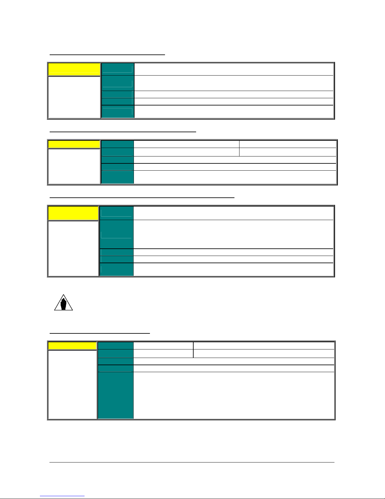
PROGRAMMING
These two parameters allow selecting two measures to be displayed on the Root
out of the measures on the Root page
These four parameters allow selecting four measures to be displayed on the
, while bit 1 relates to
INSTRUCTIONS
P268 (P268a) Measure n.1 (n.2) on Root Page
P268 / P268a Range M000 M090 (see the MEASURES MENU)
SINUS PENTA
Default
P268y (P268z) Scaling of Measure n.1 (n.2) on Root page
P268y / P268z Range
P268b (P268c, P268d, P268e) Measure n.1 (n.2, n.3, n.4) on Keypad Page
P268b, P268c,
P268d, P268e
Level
Address
Function
Default
Level
Address
Function
Range M000 M090 (see the MEASURES MENU)
Default
Level
Address
Function
P268 M004 Motor Spd
P268a M000 Speed Ref.
ADVANCED
Cannot be accessed via serial link.
Page.
0 10000 0 100.00%
10000 100.00%
ADVANCED
515 / 516
These parameters allow scaling the readwhich have been selected with parameters P268 and P268a.
P268b M006 Mot.Freq.
P268c M026 Motor Current
P268d M004 Motor Spd
P268e M000 Speed Ref.
ADVANCED
Cannot be accessed via serial link.
Keypad Page.
NOTE
P269 Disable LOC/REM FWD/REV Keys
P269 Range
Function
Measure n. 4 is available in the measure Keypad page only. The reference to measure
n. 4 is available for the remaining Keypad pages.
0 3
Default
Level
Address
0 0:[No No]
ENGINEERING
869
This parameter allows disabling the LOC/REM and/or the FWD/REV key.
This is a bit-controlled parameter: bit 0 relates to LOC/REM
FWD/REV. Set 0 to select [NO], set 1 to select [Yes].
P269 = 0 both keys are enabled.
P269 = 1 the LOC/REM key is disabled.
P269 = 2 the FWD/REV key is disabled.
P269 = 3 both keys are disabled.
0:[No No] - 3:[YES YES]
85/452
Page 86
SINUS PENTA
PROGRAMMING
INSTRUCTIONS
12. RAMPS MENU
12.1. Overview
An acceleration/deceleration ramp is a function allowing linear variations of the motor speed.
The ramp time is the time the motor takes to reach its max. speed when it starts from zero speed (or the time the
motor takes to reach 0 speed when decelerating).
Four pairs of programmable values are available. Each pair defines the motor acceleration time and deceleration time.
The unit of measure of the basic time period is assigned to each pair of values.
In the Ramps menu, you can set the acceleration and deceleration times for the four speed ramps available for
ordinary operation, for the torque ramp and the speed/torque ramp in JOG mode.
Using two special parameters, you can also set the start rounding off and the end rounding off for the acceleration
ramps, while two different parameters allow setting the start rounding off and the end rounding off for the deceleration
ramps. A fifth parameter allows selecting the ramps for the preset rounding off.
12.1.1. DESCRIPTION OF THE SPEED RAMPS
For the four speed ramps that can be selected through a combination of the digital inputs set in C167 and C168, you
can set the following: acceleration time, deceleration time and their units of measure, allowing increasing the
programmable time range.
P009 Ramp Up Time 1
P010 Ramp Down Time 1
P012 Ramp Up Time 2
P013 Ramp Down Time 2
P014 Unit of Measure for Ramp Times 1 and 2
P015 Ramp Up Time 3
P016 Ramp Down Time 3
P018 Ramp Up Time 4
P019 Ramp Down Time 4
P020 Unit of Measure for Ramp Times 3 and 4
The set ramp time corresponds to the time the speed reference takes to reach the max. speed (from 0 rpm) as an
absolute value between min. speed and max. speed of the selected motor (C028 and C029 for motor 1, and so on).
The time unit of measure may have the following values:
0 0.01 s
1 0.1 s
2 1 s
3 10 s
The programmable range may be 0s – 327000s.
Example of a speed ramp:
Table 18: Example of a Speed Ramp.
P014 Range P009 – P010
Value Coding Min. Max.
0 0.01 s 0 327.00 s
1 0.1 s 0 3270.0 s
2 1s 0 32700 s
3 10 s 0 327000 s
86/452
Page 87
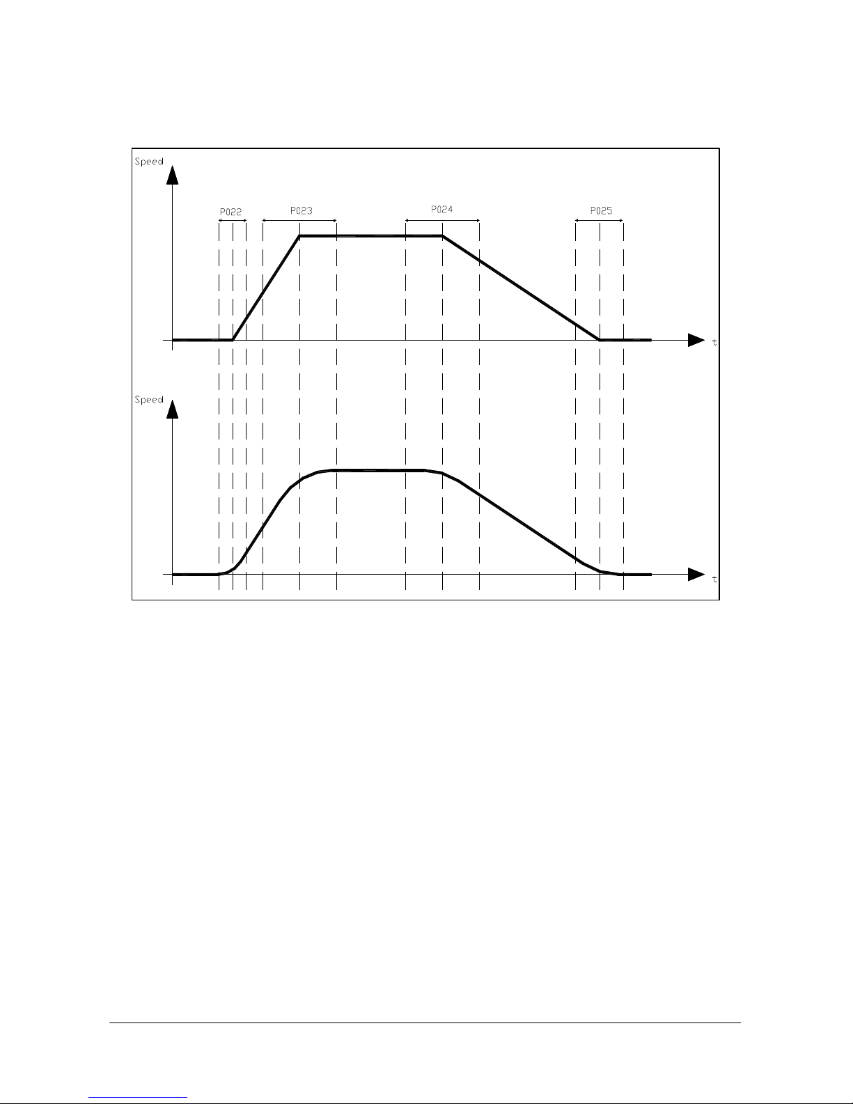
PROGRAMMING
INSTRUCTIONS
The factory setting of the unit of measure is 0.1 s; the ramp time is 10 sec.
SINUS PENTA
Figure 4: Example of S ramps.
You can also select the rounding off and the rounding off percentage for the 4 stages of starting ramp up and the
starting ramp down, and for the end ramp up and the end ramp down (S ramps). The ramp rounding off allows
reaching the reference end value with a zero tangent, both while accelerating and while decelerating, thus suppressing
torque peaks that could damage mechanical couplings.
The rounding off is expressed as a percentage of the ramp time it relates to; if used, it allows increasing the preset
ramp time by half the sum value of the two rounding off values. Its effect is shown in the figures below.
Example: P009 = 10sec ; P021 = 1111 binary (rounding off selected for all four ramps); P022 = 50%; P023 = 50%
The resulting ramp up time is as follows:
P009 + (( P009* (P022+P023)/2 )/100 ) = 10 + (( 10* (50+50)/2 )/100 ) = 15 sec
The effect of this rounding off can be seen in the figures below:
87/452
Page 88
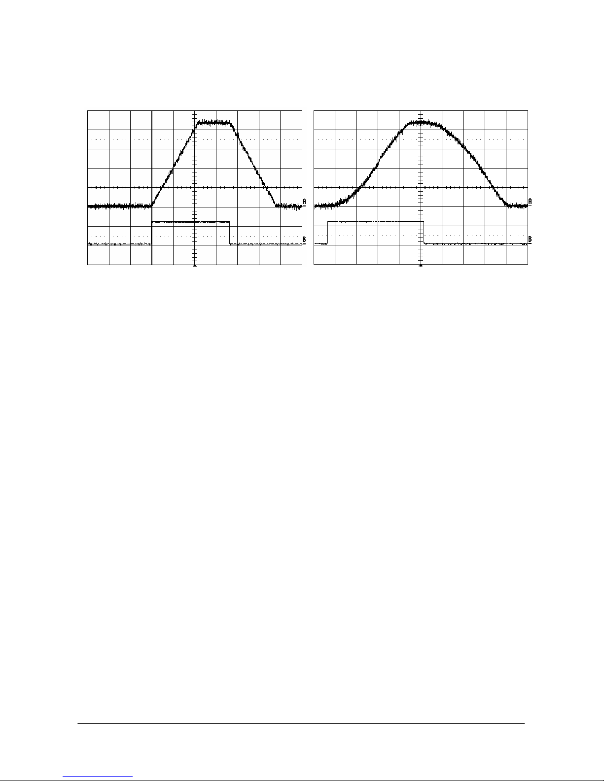
SINUS PENTA
PROGRAMMING
INSTRUCTIONS
The figure shows two patterns for the ramp reference. The first pattern is not rounded off; the second pattern has the
same ramp times, but different rounding off values are applied to the start/end ramp up/down time.
Figure 5: Speed profile without Rounding Off and with Rounding Off 2 (example).
In the figures above, the run command is represented by the high level of the second signal. Note that the time the
reference takes to reach constant rpm depends not only on the ramp times, but also on the rounding off values you
have defined.
88/452
Page 89
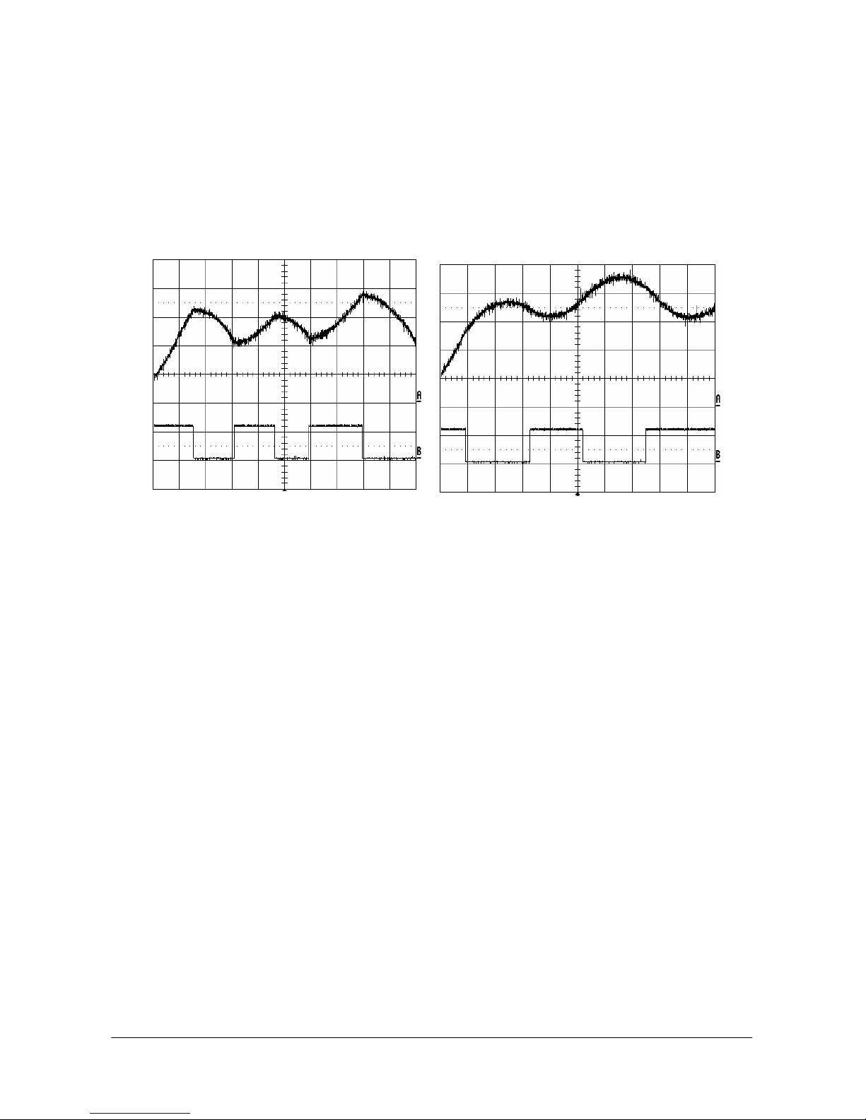
PROGRAMMING
INSTRUCTIONS
SINUS PENTA
Acceleration RESET function.
This parameter has effect only if S ramps are used. Parameter P031 enables to reset acceleration when reference
trends change.
Whenever a speed reference trend changes, the motor acceleration is instantly set to zero and the ramp output
reference will be computed considering the preset rounding off (see Figure 6). The figure shows the instant when
deceleration begins; the rounding off value assigned to the speed reference when the gradient changes is the value set
for the deceleration starting stage.
If parameter P031 is set to [No], acceleration is brought to zero before the speed reference starts decreasing, then
deceleration begins with the preset pattern.
Figure 6: Speed profile with Acceleration Reset - Yes to No (Example).
12.1.2. DESCRIPTION OF THE TORQUE RAMPS
If the control algorithm is VTC or FOC and if it is controlled by setting “Torque” (C011 for motor 1, C054 for motor 2,
and C097 for motor 3 respectively), the reference is “ramped“ based on the values set in parameter P026 (torque
increase ramp time), P027 (torque decrease ramp time), and P028 (unit of measure for the ramp times). The ramp up
time setting is the time the output torque reference takes to go from 0 to the max. value (as an absolute value) between
Torque min. and Torque max. of the selected motor (C047, C048 for motor 1 and so on).
89/452
Page 90
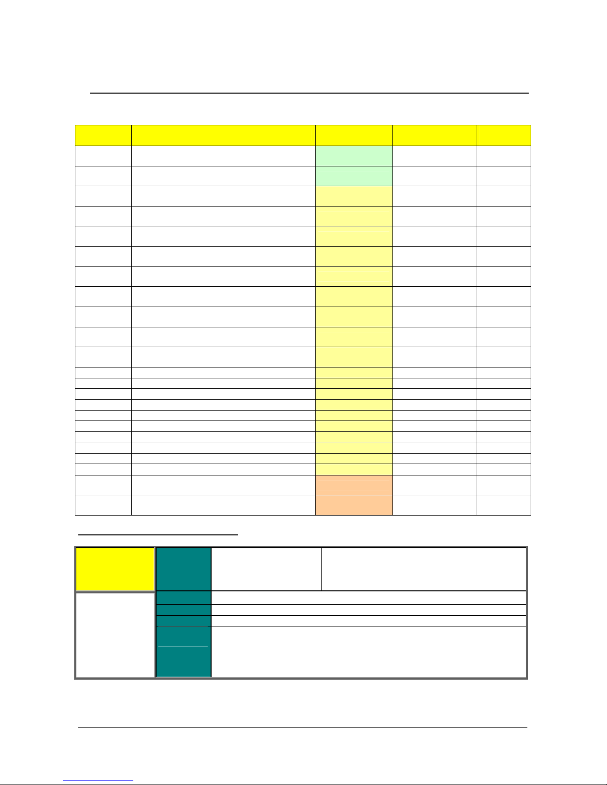
SINUS PENTA
Determines the time the reference takes to go from 0 rpm to the max. preset
speed (considering the max. value between absolute values for max. speed and
If S ramps are used, the actual time the reference takes to reach constant rpm
12.2. List of Parameters P009 to P033
Table 19: List of parameters P009 to P033.
Parameter
P009
P010
P012
P013
P014
P015
P016
P018
P019
P020
P021
P022
P023
P024
P025
P026
P027
P028
P029
P030
P031
P032
P033
P009 Speed Ramp 1: Acceleration Time
Speed ramp 1: acceleration time BASIC
Speed ramp 1: deceleration time BASIC
Speed ramp 2: acceleration time ADVANCED
Speed ramp 2: deceleration time ADVANCED
Speed ramps 1and 2: time unit of measure ADVANCED
Speed ramp 3: acceleration time ADVANCED
Speed ramp 3: deceleration time ADVANCED
Speed ramp 4: acceleration time ADVANCED
Speed ramp 4: deceleration time ADVANCED
Speed ramps 3 and 4: time unit of measure ADVANCED
Selection for S ramp rounding off ADVANCED
Acceleration S ramp: start rounding off time ADVANCED 50% 622
Acceleration S ramp: end rounding off time ADVANCED 50% 623
Deceleration S ramp: start rounding off time ADVANCED 50% 624
Deceleration S ramp: end rounding off time ADVANCED 50% 625
Torque ramp time: up ADVANCED 5 s 626
Torque ramp time: down ADVANCED 5 s 627
Unit of measure for torque ramp time ADVANCED 0.1 s 628
Jog ramp acceleration time ADVANCED 1 s 629
Jog ramp deceleration time ADVANCED 1 s 629
Gradient variation acceleration reset ADVANCED 1 : [YES] 630
Fire Mode Ramp: acceleration time ENGINEERING
Fire Mode Ramp: deceleration time ENGINEERING
P009 Range 0 32700
Default See Table 74 and Table 78
Address 609
FUNCTION User Level
0 327.00 s if P014=0 0.01 s
0 3270.0 s if P014=1 0.1 s
0 32700 s if P014=2 1 s
0 327000 s if P014=3 10 s
Level BASIC
PROGRAMMING
INSTRUCTIONS
Default
Values
See Table 74 and
Table 78
See Table 74 and
Table 78
See Table 74 and
Table 78
See Table 74 and
Table 78
See Table 74 and
Table 78
See Table 74 and
Table 78
See Table 74 and
Table 78
See Table 74 and
Table 78
See Table 74 and
Table 78
See Table 74 and
Table 78
See Table 74 and
Table 78
See Table 74 and
Table 78
See Table 74 and
Table 78
MODBUS
Address
609
610
612
613
614
615
616
618
619
620
621
632
633
Function
min. speed set for the selected motor).
exceeds the time set in P009 for a percentage equal to (P022+P023)/2.
90/452
Page 91
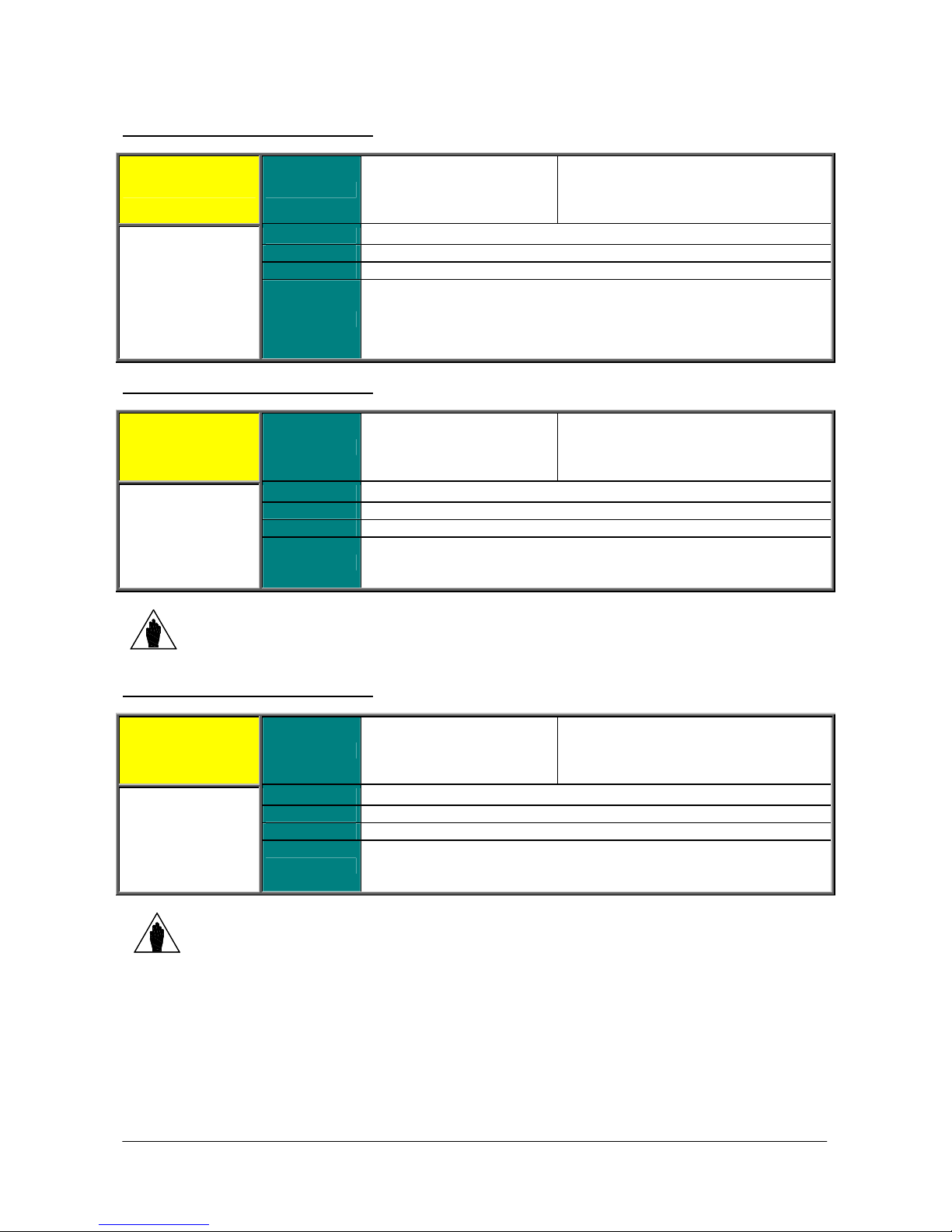
PROGRAMMING
e the reference takes to go from the max. preset speed
(considering the max. value between absolute values for max. speed and min.
If S ramps are used, the actual time the reference takes to reach 0 speed
INSTRUCTIONS
P010 Speed Ramp 1: Deceleration Time
P010 Range 0 32700
Default
Level
Address
See Table 74 and Table 78
BASIC
610
Determines the tim
SINUS PENTA
0 327.00 s if P014=0 0.01 s
0 3270.0 s if P014=0 0.1 s
0 32700 s if P014=0 1 s
0 327000 s if P014=0 10 s
Function
P012 Speed Ramp 2: Acceleration Time
P012 Range 0 32700
Default
Level
NOTE
P013 Speed Ramp 2: Deceleration Time
P013 Range 0 32700
Address
Function Same as ramp 1 (see P009).
Values for ramp 2 can be applied to the reference provided that multiramp digital inputs
are set up and that ramp 2 is selected (see the DIGITAL INPUTS MENU).
Default
Level
Address
speed set for the selected motor) to zero rpm.
exceeds the time set in P010 for a percentage equal to (P024+P025)/2.
See Table 74 and Table 78
ADVANCED
612
See Table 74 and Table 78
ADVANCED
613
0 327.00 s if P014=0 0.01 s
0 3270.0 s if P014=0 0.1 s
0 32700 s if P014=0 1 s
0 327000 s if P014=0 10 s
0 327.00 s if P014=0 0.01 s
0 3270.0 s if P014=0 0.1 s
0 32700 s if P014=0 1 s
0 327000 s if P014=0 10 s
Function Same as ramp 1 (see P010).
NOTE
Values for ramp 2 can be applied to the reference provided that multiramp digital inputs
are set up and that ramp 2 is selected (see the DIGITAL INPUTS MENU).
91/452
Page 92
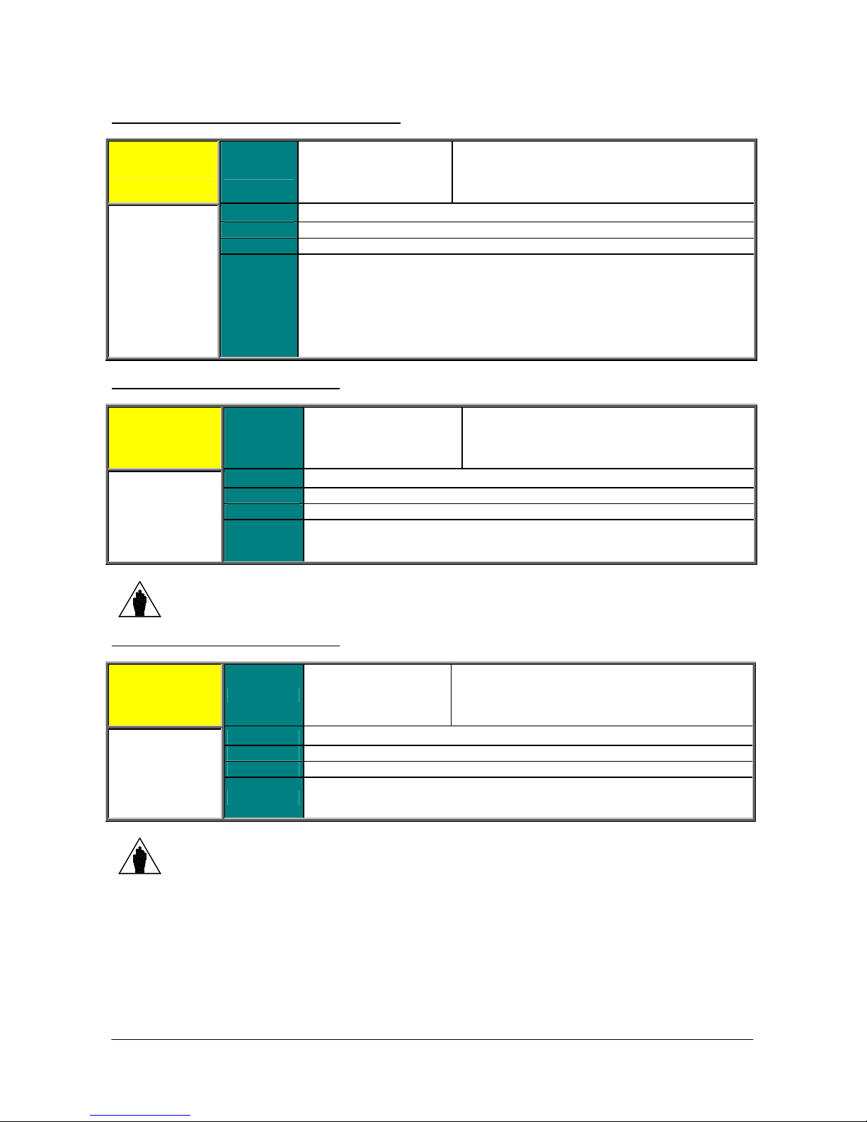
SINUS PENTA
and
and
P014 Speed Ramps 1 and 2: Time Unit of Measure
P014 Range 0 3
Default
Level
Address
Function
P015 Speed Ramp 3: Acceleration Time
P015 Range 0 32700
Default
Level
Address
See Table 74 and Table 78
ADVANCED
614
Defines the unit of measure for the time periods for speed ramp 1 (P009
P010), for speed ramp 2 (P012 and P013), and for ramps in Fire Mode (P032
P033). The allowable programmable range may be extended from 0 s to 327000s.
E.g.
P014=1 then P009=100; this means P009 = 100 x 0.1 s = 10 s
P014=0 then P009=100; this means P009 = 100 x 0.01 s = 1 s
P014=3 then P009=100; this means P009 = 100 x 10 s = 1000 s
See Table 74 and Table 78
ADVANCED
615
PROGRAMMING
INSTRUCTIONS
0 0.01 s
1 0.1 s
2 1 s
3 10 s
0 327.00 s if P020=0 0.01 s
0 3270.0 s if P020=0 0.1 s
0 32700 s if P020=0 1 s
0 327000 s if P020=0 10 s
Function Same as ramp 1 (see P009).
NOTE
P016 Speed Ramp 3: Deceleration Time
P016 Range 0 32700
NOTE
Values for ramp 3 can be applied to the reference provided that multiramp digital inputs are
set up and that ramp 3 is selected (see the DIGITAL INPUTS MENU).
Default
Level
Address
Function Same as ramp 1 (see P010).
Values for ramp 3 can be applied to the reference provided that multiramp digital inputs
are set up and that ramp 3 is selected (see the DIGITAL INPUTS MENU).
See Table 74 and Table 78
ADVANCED
616
0 327.00 s if P020=0 0.01 s
0 3270.0 s if P020=0 0.1 s
0 32700 s if P020=0 1 s
0 327000 s if P020=0 10 s
92/452
Page 93
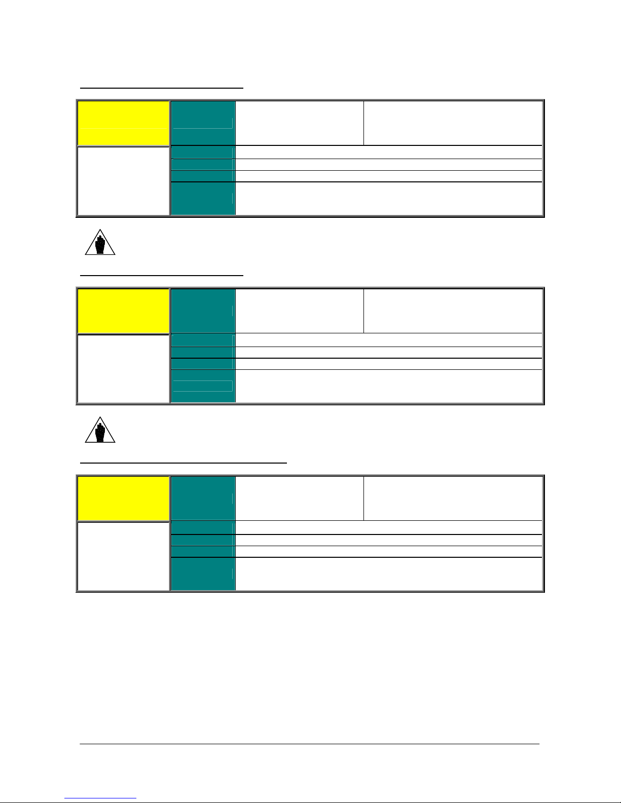
PROGRAMMING
ble range may
INSTRUCTIONS
P018 Speed Ramp 4: Acceleration Time
P018 Range 0 32700
Default
Level
NOTE
P019 Speed Ramp 4: Deceleration Time
P019 Range 0 32700
Address
Function Same as ramp 1 (see P009).
Values for ramp 4 can be applied to the reference provided that multiramp digital inputs
are set up and that ramp 4 is selected (see the DIGITAL INPUTS MENU).
Default
Level
Address
SINUS PENTA
0 327.00 s if P020=0 0.01 s
0 3270.0 s if P020=0 0.1 s
0 32700 s if P020=0 1 s
0 327000 s if P020=0 10 s
See Table 74 and Table 78
ADVANCED
618
0 327.00 s if P020=0 0.01 s
0 3270.0 s if P020=0 0.1 s
0 32700 s if P020=0 1 s
0 327000 s if P020=0 10 s
See Table 74 and Table 78
ADVANCED
619
Function Same as ramp 1 (see P010).
NOTE
P020 Speed Ramps 3 and 4: Time Unit of Measure
P020 Range 0 3
Values for ramp 4 can be applied to the reference provided that multiramp digital inputs
are set up and that ramp 4 is selected (see the DIGITAL INPUTS MENU).
Default See Table 74 and Table 78
Level ADVANCED
Address 620
Defines the unit of measure for the times for speed ramp 3, P015 and P016,
Function
and speed ramp 4, P020 and P018. The allowable programma
be extended from 0 s to 327000s.
0 0.01 s
1 0.1 s
2 1 s
3 10 s
93/452
Page 94
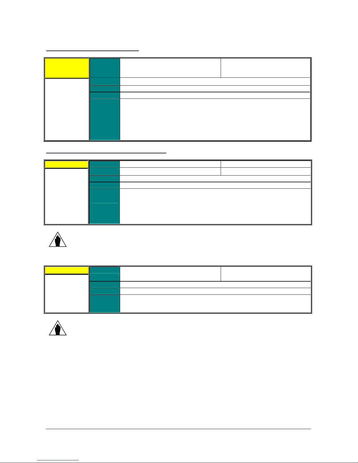
SINUS PENTA
In this parameter, you can select the bit corresponding to the ramp to be rounded
The ramp rounding off allows reaching the reference end value with a zero tangent,
both while accelerating and while decelerating, thus suppressing torque peaks that
Sets the rounding off time period for the first stage of the acceleration ramp. This
parameter is expressed as a percentage of the acceleration ramp time of the active
Example: the second ramp is active with an acceleration ramp time of 5sec, P022 =
50%. Therefore, reference acceleration is limited for the first 2.5 sec of the ramp
Sets the rounding off time period for the end stage of the acceleration ramp. This
ed as a percentage of the acceleration ramp time of the active
P021 Selection for Ramp Rounding Off
0000b 1111b binary
P021 Range
Default
Level
Address
0x0000 0x000F hexadecimal
0 15
See Table 74 and Table 78
ADVANCED
621
PROGRAMMING
INSTRUCTIONS
0000b (no S ramps)
1111b (all S ramps)
Function
P022 Acceleration Ramp: Start Rounding Off Time
P022 Range 0 100 0 100 %
Default
Level
Address
Function
NOTE
P023 Acceleration Ramp: End Rounding Off Time
P023 Range
Default
Level
Address
off.
Example:
P021 = 0011b = 3 decimal ramps 1 and 2 are rounded off.
could damage mechanical couplings.
50 50%
ADVANCED
622
ramp.
time.
When using parameter P022, the preset acceleration ramp time is increased by:
(P022%)/2.
0 100 0 100 %
50 50%
ADVANCED
623
Function
NOTE
parameter is express
ramp.
When using parameter P023, the preset acceleration ramp time is increased by:
(P023%)/2.
94/452
Page 95
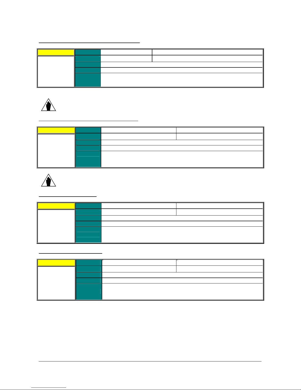
PROGRAMMING
. The only difference is that this rounding off function is
. The only difference is that this rounding off function is
Defines the time taken by the torque reference of the selected motor to go to zero
from max. value (as an absolute value between Torque min. and Torque max.);
Defines the time taken by the torque reference of the selected motor to go from max.
INSTRUCTIONS
P024 Deceleration Ramp: Start Rounding Off Time
P024 Range
Default
Level
P025 Deceleration Ramp: End Rounding Off Time
P025 Range
Address
Function
NOTE
Default
Level
Address
Function
0 100 0 100 %
50 50%
ADVANCED
624
See the function for P022
applied to the first stage of a deceleration ramp.
When using parameter P024, the preset deceleration ramp time is increased by:
(P024%)/2.
0 100 0 100 %
50 50%
ADVANCED
625
See the function for P023
applied to the last stage of a deceleration ramp.
SINUS PENTA
NOTE
P026 Torque Ramp Time: Up
P027 Torque Ramp Time: Down
P026 Range
Default
P027 Range
Address
Function
Default
Address
Function
When using parameter P025, the preset deceleration ramp time is increased by:
(P025%)/2.
Level
Level
0 32700
500 50 sec
ADVANCED
626
(C047–C048 for motor 1 and so on).
0 32700
500 50 sec
ADVANCED
627
value to zero (as an absolute value between Torque min. and Torque max.); (C047–
C048 for motor 1 and so on).
Function of P028
Function of P028
95/452
Page 96
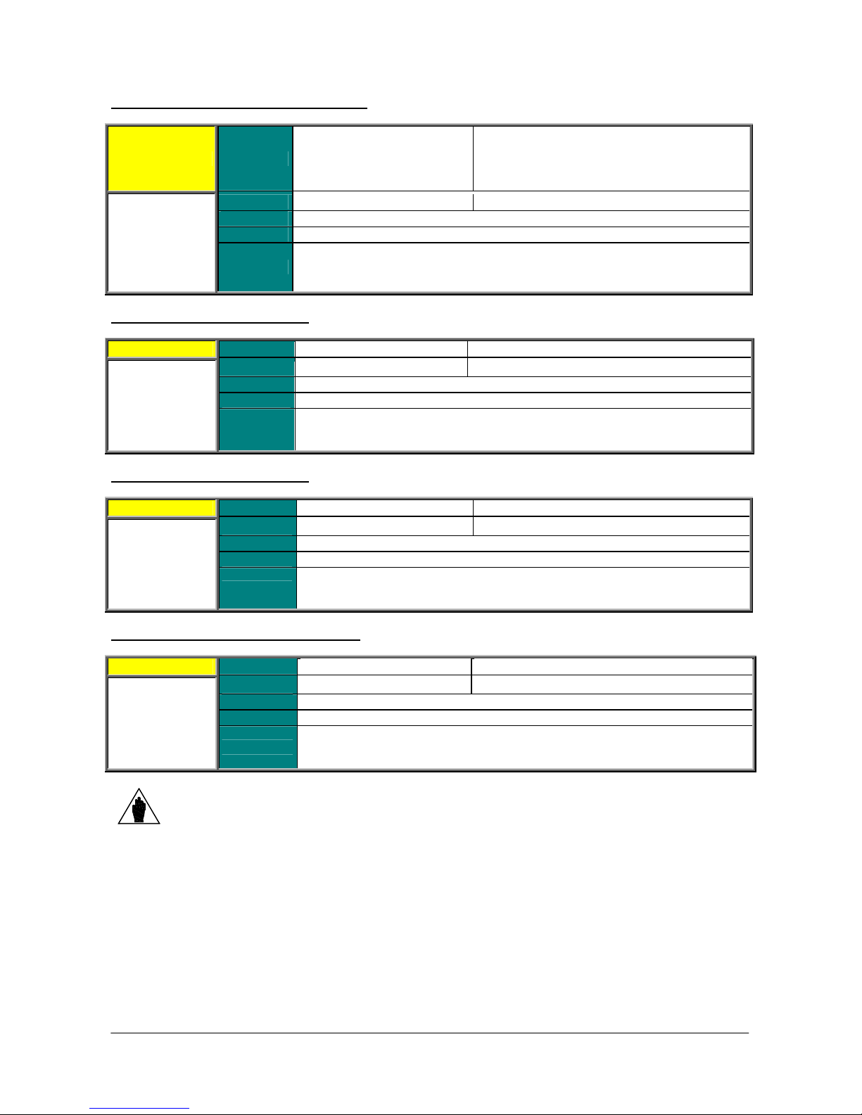
SINUS PENTA
nit of measure for
The preset time corresponds to the time the “ramped” speed/torque reference takes
The preset time corresponds to the time the “ramped” speed/torque reference takes
g from acceleration to
deceleration and vice versa (reference gradient). For more details, see the
P028 Unit of Measure for Torque Ramp Time
P028 Range 0 3
Default
Level
P029 Jog Ramp Acceleration Time
P029 Range
Address
Function
Default
Level
Address
1
ADVANCED
628
Defines the unit of measure for the torque ramp times. See the u
ramp 1 (par. P014).
0 6500 0 6500 sec
1 1sec
ADVANCED
629
PROGRAMMING
INSTRUCTIONS
0 0.01 s
1 0.1 s
2 1 s
3 10 s
1 0.1 s
Function
P030 Jog Ramp Deceleration Time
P030 Range
Default 1 1sec
Level ADVANCED
P031 Gradient Variation Acceleration Reset
P031 Range
NOTE
Address 630
Function
Default
Level
Address
Function
Parameter P031 is interlocked with parameter C210 (Automatic extension of down ramp) so
that P031 = 0:No cannot be programmed in conjunction with C210 [With resistor].
to go from zero to the JOG speed/torque value (P070).
0 6500 0 6500 sec
to go from the JOG speed/torque value (P070) to zero.
0 1
1 1: [Yes]
ADVANCED
631
Defines whether acceleration is reset or not when switchin
description of the speed ramps at the beginning of this section.
0: [No] ; 1: [Yes]
96/452
Page 97
PROGRAMMING
INSTRUCTIONS
P032 Fire Mode Acceleration Ramp
P032 Range 0 32700
Default
Level
Address
SINUS PENTA
0 327.00 s if P014=0 0.01 s
0 3270.0 s if P014=1 0.1 s
0 32700 s if P014=2 1 s
0 327000 s if P014=3 10 s
See Table 74 and Table 78
ENGINEERING
632
Function
P033 Fire Mode Deceleration Ramp
P033 Range 0 32700
Default
Level
Address
Function
This ramp is used to accelerate the motor when in Fire Mode.
0 327.00 s if P014=0 0.01 s
0 3270.0 s if P014=1 0.1 s
0 32700 s if P014=2 1 s
0 327000 s if P014=3 10 s
See Table 74 and Table 78
ENGINEERING
633
This ramp is used to decelerate the motor when in Fire Mode.
97/452
Page 98
SINUS PENTA
PROGRAMMING
INSTRUCTIONS
13. INPUTS FOR REFERENCES MENU
13.1. Processing Speed/Torque References
The “main reference” is the value, at constant rpm, for the controlled physical variable (speed or torque) (M000,
M007) “required” for the drive.
This reference is acquired by the drive only if the START command is active and the drive is RUNNING, otherwise it is
ignored.
The main reference is the reference at constant rpm: when the drive is RUNNING, it will increment the speed or
torque set–point which will reach the main reference with a timed ramp (see the RAMPS MENU).
The drive operating mode is factory-set to MASTER with a speed reference. In SLAVE mode, a torque reference is
used; this operating mode may be configured for VTC control (Vector Torque Control) and FOC control (Field Oriented
Control) only.
The control algorithm and the MASTER/SLAVE mode can be set for each of the 3 programmable motors, depending
on which motor is active at that moment (motor 1, motor 2 or motor 3).
To enable the SLAVE mode, set the following parameters to 1 or 2:
C011 (motor 1)
C054 (motor 2)
C097 (motor 3)
The SLAVE mode may also be selected through a digital input (see the DIGITAL INPUTS MENU).
When the main reference is acquired by the drive (RUNNING on), it becomes the reference for the time ramps
generating the current speed/torque set–point for the connected motor.
The set up of the main reference is based on a number of parameters included in several menus:
Table 20: Parameters used for the Inputs for References Menu.
Parameters Menu Contents
Scaling parameters for references sent from analog inputs
REF, AIN1, AIN2.
Scaling parameters for references sent from encoder and
frequency input.
P050 P074 References
Parameters for changes made using the UP and DOWN
keys.
Parameter for JOG reference setting.
Parameter for drive disabling in case of reference at min.
value.
P390 P399
P080 P098 Multispeed
P105 P108
P115 P121
C143 C146 Control Method
C011, C028, C029
C054, C071, C072
C097, C114, C115
C047, C048
C090, C091
C133, C134
The following pages contain block diagrams illustrating speed reference processing (Figure 6) and torque reference
processing (Figure 7). Menus and parameters used are also stated.
References from
option board
Prohibit Speed
Reference
Variation Percent
Control of Motor
1
Control of Motor
2
Control of Motor
3
Current Limit for
Motor 1
Current Limit for
Motor 2
Current Limit for
Motor 3
Scaling parameters for references sent from analog inputs
XAIN4, XAIN5.
Parameters setting preset multispeed values to be selected
through digital inputs.
Parameters setting prohibit speed values.
Parameters setting slowing down values percent to be
selected through digital inputs.
Parameters setting the reference source.
Parameter setting the Master (speed) mode or the Slave
(torque) mode. Parameters setting the min. speed or the
max. speed.
Parameters setting the min. torque and the max. torque.
98/452
Page 99
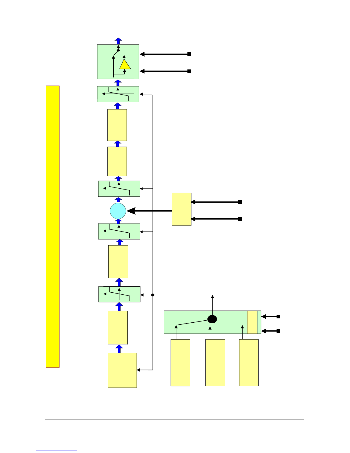
PROGRAMMING
i
t
8
Inversion
-
1
Saturatio
n
Cw/CC
W
REV
P000662-b
INSTRUCTIONS
SINUS PENTA
Speed
Prohib
Variation
Reference
P105:P10
cent
Per
P115:P121
Saturation
N
W
O
D
+
n
o
i
t
a
r
u
t
a
S
8
9
0
P
:
speed
0
8
0
P
Multi
P067 : P069
Speed Reference computing
Saturation
Method
Control
Input for
C145, C146
C143, C144,
4
4
6
7
0
0
P
P
:
:
0
1
5
7
0
0
Reference
P
P
Scaling
9
9
3
P
:
0
9
3
P
Figure 7: Speed Reference computing.
1
r
o
t
o
M
9
Control
C011, C028, C02
Control
Motor 2
Motor 3
C054, C071, C072
UP
Up Down Variation
Motor 1
Control
C009
n
o
i
t
c
°
e
l
3
e
s
Motor
r
o
t
o
m
e
v
i
2°
t
c
Motor
A
Control
C097, C114, C115
99/452
Page 100
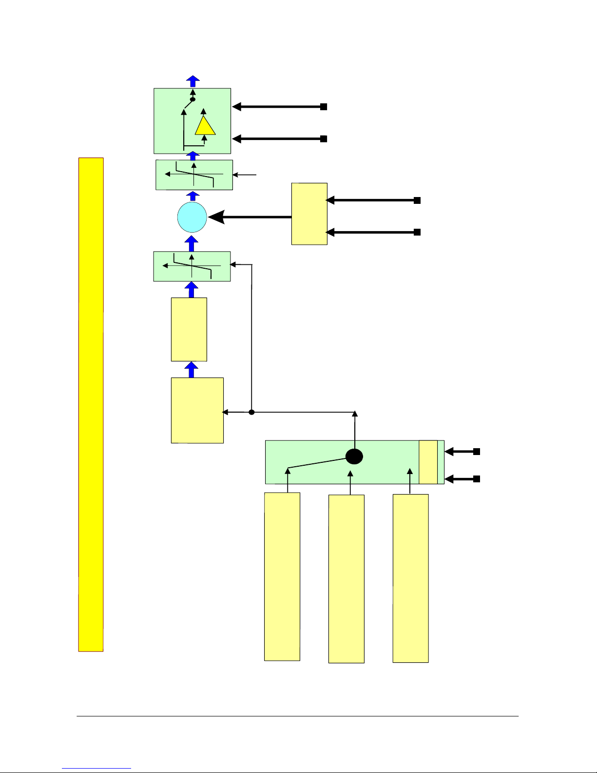
SINUS PENTA
3
°Mo
t
orMot
or
1
configuration
P000661-b
I
nvers
ion
- 1
Cw/CC
W
REV
Saturatio
n
P067 : P0
6
9
U
P
DOW
N
+
U
p
Do
wn
Variati
o
n
g
n
i
t
u
p
m
o
c
e
c
n
e
r
e
f
e
R
e
u
q
r
o
T
turation
Sa
l
o
r
t
n
o
C
,
4
d
4
o
1
h
t
C
,
e
3
M
4
1
C145, C146
C
e
c
n
e
r
e
f
e
Input for
R
4
4
7
6
0
0
P
P
:
:
1
0
7
5
0
0
P
P
Scaling
9
9
3
P
:
0
9
3
P
8
4
0
C
,
7
4
0
C
Motor Limits n.1
Motor Limits n.2
1
9
0
C
,
0
9
0
C
Motor Limits n.3
PROGRAMMING
INSTRUCTIONS
C009
4
3
1
C
,
3
3
1
C
2°
Motor
Active Motor Selection
100/452
Figure 8: Torque Reference computing.
 Loading...