

Page 1
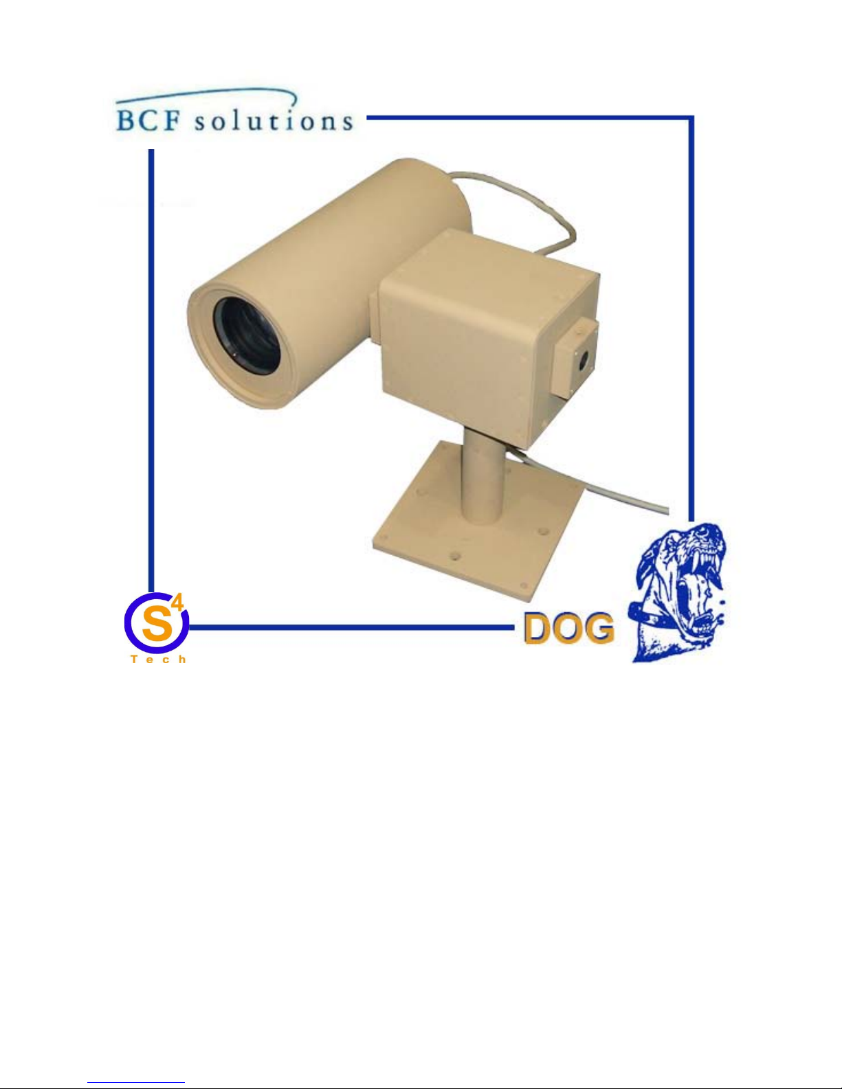
DIGITAL OBSERVATION GUARD
HIGH PERFORMANCE LOW
PROFILE PTZ KIT USER MANUAL
DPTZ-Kit-1/2-v1_manual-v2.2
Version 2.2
May 17, 2013
Page 2

Table of Contents
High Performance Low Profile PTZ Kit Description ................................................................................... 3
High Performance Low Profile PTZ Unit Basic Operation .......................................................................... 4
Mounting the High Performance Low Profile PTZ Units ............................................................................ 5
Surface Mounting the High Performance Low Profile PTZ Unit ............................................................ 5
Wall or Pole Mounting the Pan-Tilt Unit ................................................................................................. 7
Connecting the Camera to the Pan Tilt Unit ............................................................................................... 10
Terminating and connecting the CAT-5 Cable ........................................................................................... 12
Connecting the Thermal Camera and IR Illuminator ................................................................................. 15
Connecting the DOG IR Illuminator ...................................................................................................... 16
Connecting the IR Illuminator Cable .................................................................................................. 16
Connecting the Thermal Camera ............................................................................................................ 17
Connecting PTZ Units to the Base Station ................................................................................................. 18
Troubleshooting .......................................................................................................................................... 20
Contact Info/Tech Support ......................................................................................................................... 21
Replacement Parts ...................................................................................................................................... 21
1
Page 3

Table of Figures
Figure 1: High Performance Low Profile PTZ Kit with Optional Military Grade Case .............................. 3
Figure 2: High Performance Low Profile PTZ Kit Identification Label ...................................................... 3
Figure 3: High Performance Low Profile PTZ Unit Channel ID Number .................................................. 4
Figure 4: Surface Mount accessories ............................................................................................................ 5
Figure 5: Attaching the Pedestal Mount Adapter Plate to the High Performance Low Profile PTZ ........... 6
Figure 6: Mounting the Pedestal onto a Surface ........................................................................................... 7
Figure 7: Attaching the Bracket to a Wall or Vertical Surface ..................................................................... 8
Figure 8: Attaching the Bracket to a Pole ..................................................................................................... 8
Figure 9: Attach Pan Tilt Unit to the Bracket ............................................................................................... 9
Figure 10: Camera Tube Mounting Hardware ............................................................................................ 10
Figure 11: Attaching Camera Tube to Pan Tilt Unit .................................................................................. 10
Figure 12: Attaching Camera Tube Cable to Pan Tilt Unit ........................................................................ 11
Figure 13: Attaching CAT-5 Cable to Pan Tilt Unit .................................................................................. 11
Figure 14: Assembled Pan Tilt Unit with Camera Tube ............................................................................ 12
Figure 15: Weatherproof Connector Parts .................................................................................................. 12
Figure 16: CAT-5 cable termination and connection ................................................................................. 13
Figure 17: Strain Relief of the Cable .......................................................................................................... 14
Figure 18: Camera Adapter Accessories .................................................................................................... 15
Figure 19: IR Illuminator/Thermal Camera Adapter Plate attachment ...................................................... 15
Figure 20: Installing an IR Illuminator ....................................................................................................... 16
Figure 21: Connecting the IR Illuminator Power Cable ............................................................................. 16
Figure 22: Attaching a Thermal Camera .................................................................................................... 17
Figure 23: Connecting the Thermal Camera Cable to the High Performance Low Profile PTZ .............. 18
Figure 24: High Performance Low Profile PTZ Unit Connection Diagram ............................................. 19
2
Page 4
High Performance Low Profile PTZ Kit Description
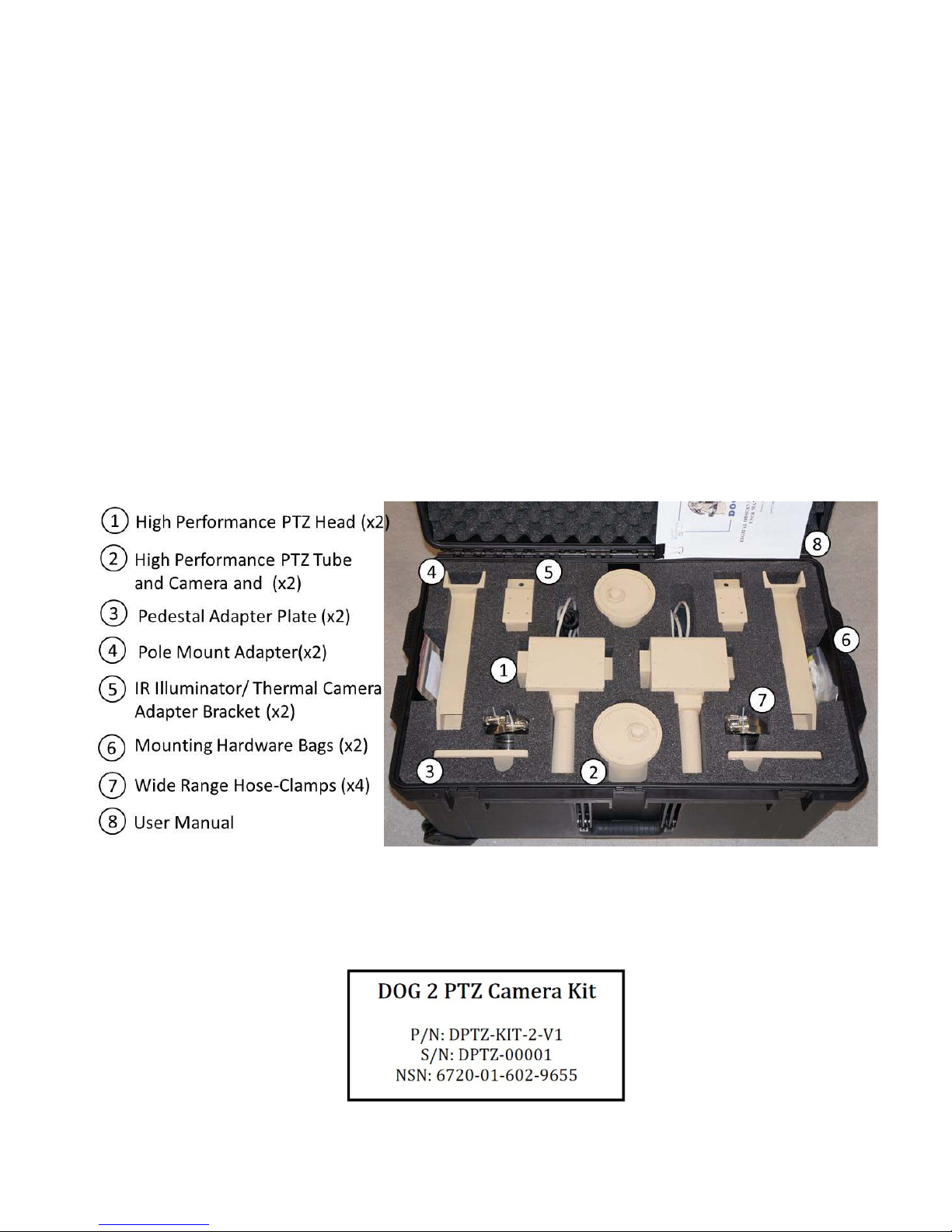
The High Performance Low Profile PTZ kit is an accessory kit for installation on the DOG Base Kit.
Each High Performanc e Low P rofile PT Z case contains 2 High Performan ce Low Profil e PTZ units with
attached zoom cameras, and associated accessories. The High Performance Low Profile PTZ units are
capable of providing 360 degrees of horizontal ( pan) motion and 180 degrees (+/ - 90◦) of vertical (tilt)
motion. The units can be either wall-mounted or pole-mounted using the Wall Mount Brackets and Pole
Mount Adapters provided in the kit. The units are also surface mountable using the Pedestal Mount
Adapter Plates, also provided in the kit. The IR Illuminator/Thermal Camera Adapter Plates allow an IR
Illuminator or Thermal Camera to be mounted if needed. This allows the IR illuminator beam (or
Thermal Camera im age) to track with the PTZ Camera as the Hi gh Performance Low Profile PTZ head
moves. Each High Performance Low P rofile PT Z unit is assigned a Channel ID reference num ber from
1 to 8 (1-4 for 4 channel DOG systems) for identification purposes. An ex ample of a High Performance
Low Profile PTZ Kit is shown in the figure below.
**WHEN RE-PACKING THE KIT, PRIOR TO POWER-DOWN, USE THE DVR DOME
CONTROLS TO POSITION THE TILT AXIS AT 0-DEGREES VERTICAL OR THE UNIT
WILL NOT FIT**
Figure 1: High Performance Low Profile PTZ Kit with Optional Military Gra de Case
Each case can be identi fied by a decal just above the handle as shown in the figure below. The “DPTZ”
stands for DOG Pan-Tilt-Zoom and is followed by the kit serial number.
Figure 2: High Performance Low Profile PTZ Kit Identification Label
3
Page 5
High Performance Low Profile PTZ Unit Basic Operation
Each High Perform ance Low Profile PT Z unit draws its power and data commands from, and transmits
its video to, the Base Station. The High P erformance Low Profile PTZ unit can be placed up to 500m
from the DOG Base Station, using CAT-5 cable with no external power source required. The High
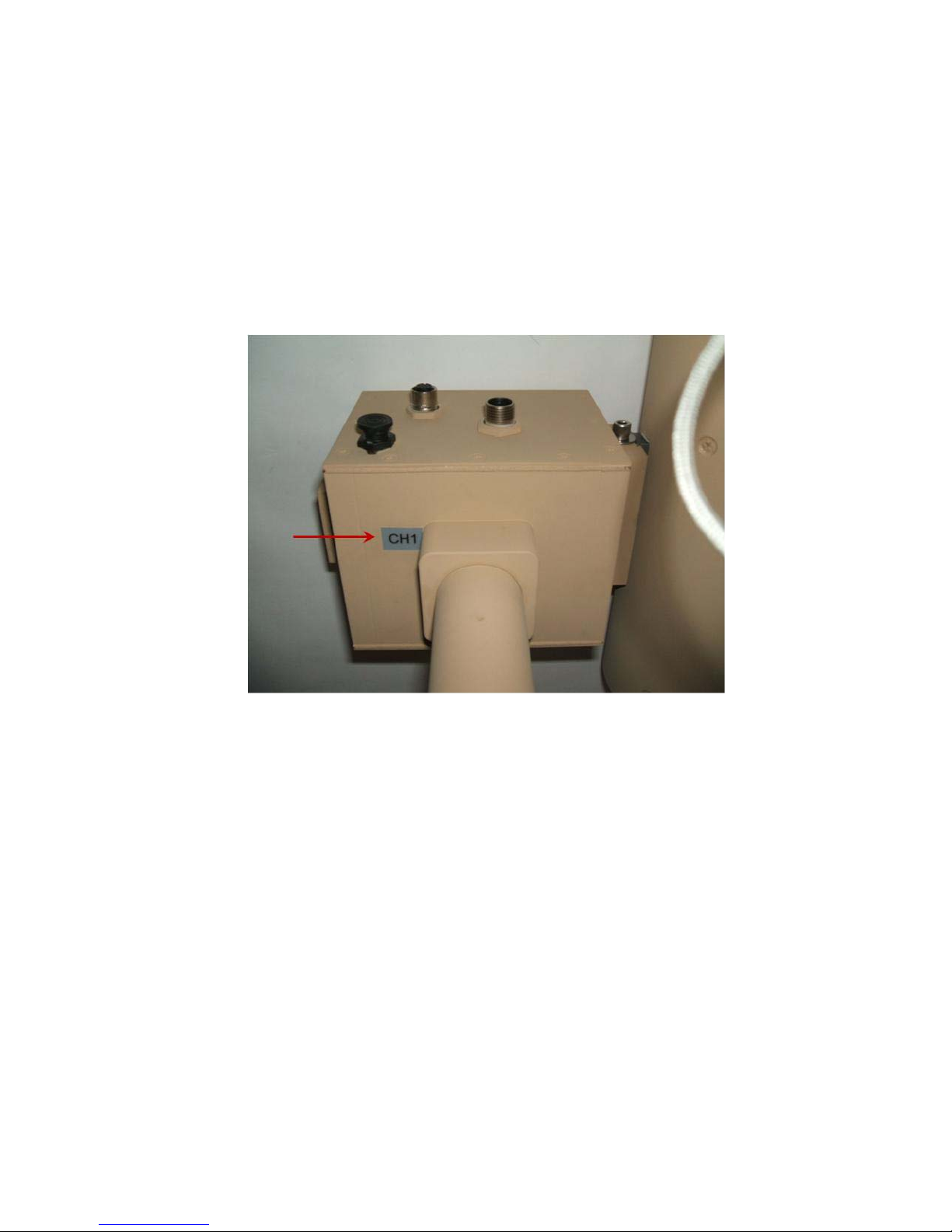
Performance Low Profile PTZ Channel ID number (1-8 for 8 channel systems and 1-4 for 4 channel
systems) is indicated by a decal on the bottom of the unit as seen in the figure below and must be
connected to the co rresp ond ing ch annel on th e B ase Stat ion. * Make sure to keep track of the channel
number of each High Performance Low Profile PTZ unit.
Figure 3: High Performance Low Profile PTZ Unit Channel ID Number
To operate the High Perfo rman ce Low Pro fi le P TZ unit, the user simply selects the channel of the camera
from the buttons on the front of the Base Station DVR and then pushes the Dome butt on on the DVR.
This brings up an on-screen message which indicates that the pan-tilt arrow buttons on the DVR are
active. At this point, pushing the arrow buttons moves the camera as indicated by the arrow buttons.
Details of the High Performance Low Profile PTZ unit setup are provided in the following sections.
4
Page 6
Mounting the High Performance Low Profile PTZ Units
The two main mounting methods of surface mounting and wall/pole mounting are covered in the
following sections.
Surface Mounting the High Performance Low Pr of il e PTZ Unit
Surface mounting the High Performance Low Profile PTZ unit to a flat surface such as a roof or pedestal
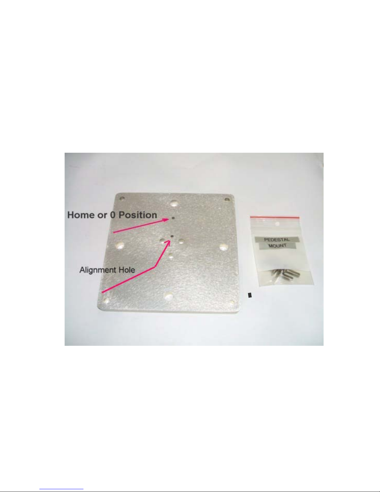
requires the attachment of a Pedestal Mount Adapter Plate using the bag of the included Pedestal Mount
screws as seen in the fi gure below. The camera Home or 0 Position indicated in the figure is the 0 degree
pan position and should be p ointed at the center of the surveil lance area. The camera will pan +/ - 180
degrees about that point. The Alignment Hole indicated in the figure is for alignment of the pan tilt unit
shaft.
Position the adapter plate, with the non-countersunk-holes against the shaft (countersunk holes on other
side of the shaft ) and align the pin on the shaft with the Alignment hole on the plate as seen in the figure
below. Insert the three 1/4-20 x 5/8 flathead machine screws and tighten the screws using a Phillips head
screwdriver, but do not tighten the screws completely until all three are inserted.
Figure 4: Surface Mount accessories
5
Page 7
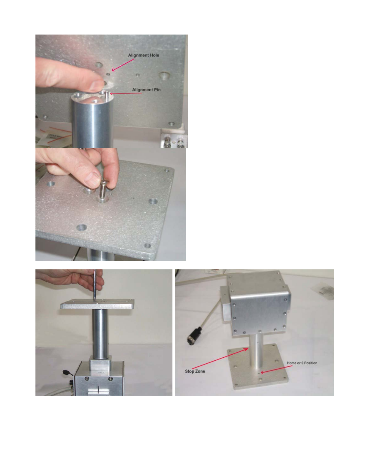
Figure 5: Attaching the Pedestal Mount Adapter Plate to the High Perfo rmance Low Profile PTZ
The High Performance Low Profile PTZ camera has a Stop Zone at +/- 180 degrees where it has to
change directions in order to keep moving. The Stop Zone is on the exact opposite side of the shaft as the
6
Page 8
Home or 0 Position as seen in the figure above. The camera should be mounted so that the Home or 0
Position is pointed at the area of interest and the Stop Zone is pointed away from the area of interest.
**Important: The Home or 0 Position hole should point to the center of the surveillance area to
avoid Stop Zone related horizontal (pan) movement delays.
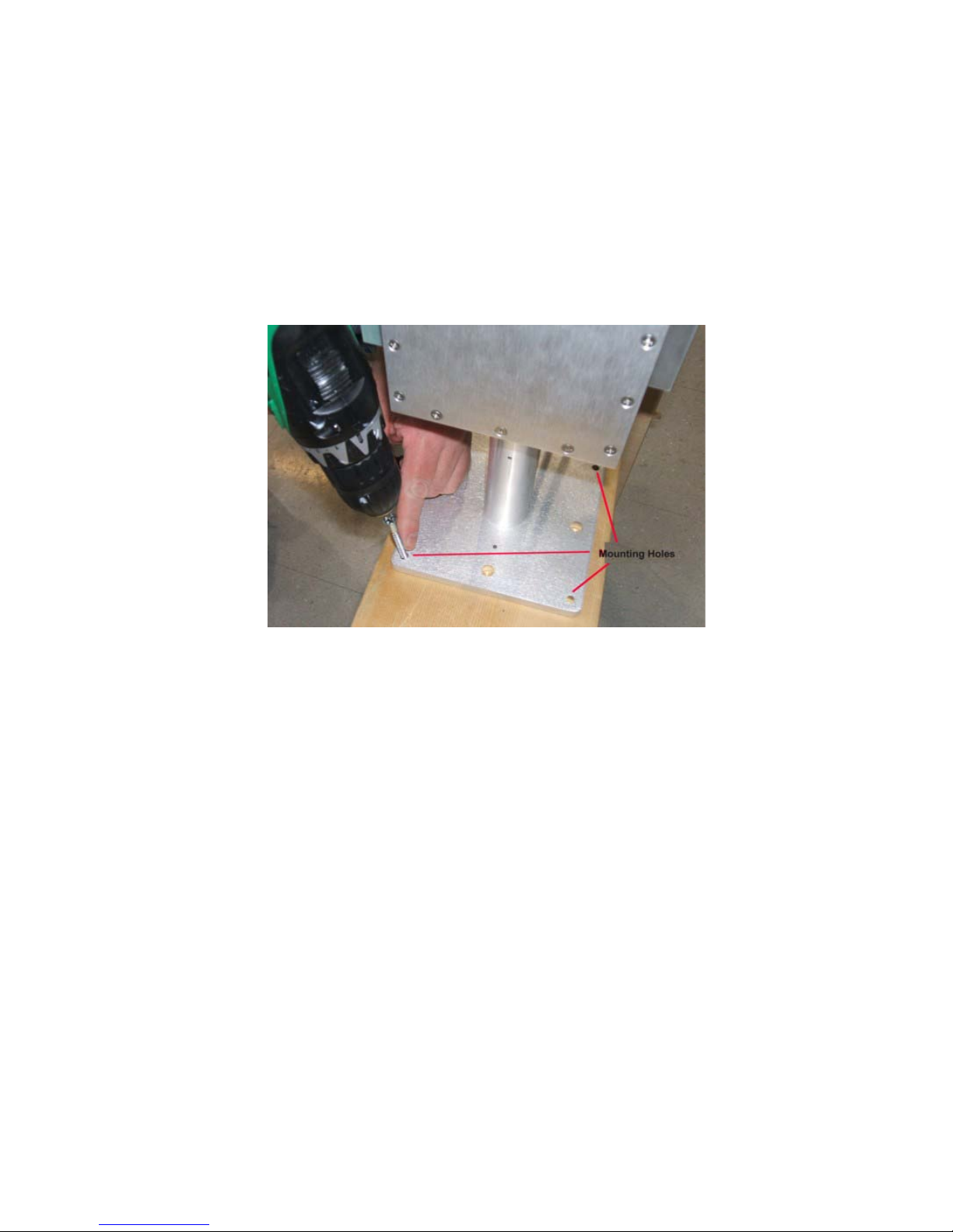
For a rooftop mount, simply place the assembled unit on a piece of pl ywood or directly onto the roof,
then drive wood o r sh eet m etal s crews (# 8 or s mal ler) through the four screw holes along the perimeter of
the Pedestal Mount Adapter Plate and into the mounting surface as shown in the figure below.
Figure 6: Mounting the Pedestal onto a Surface
Wall or Pole Mounting the Pan-Tilt Unit
The wall/pole mounting bracket provided in the kit is used for attaching to a vertical surface like a wall or
pole. It is recommended to mount the bracket to the vertical surface first, then mount the pan tilt unit and
the camera to the bracket, though this order is not necessary. To mount the bracket to a wall simply hold
the bracket on the desired location and drive wood or sheet metal screws through the four holes as seen in
the figure below.
7
Page 9
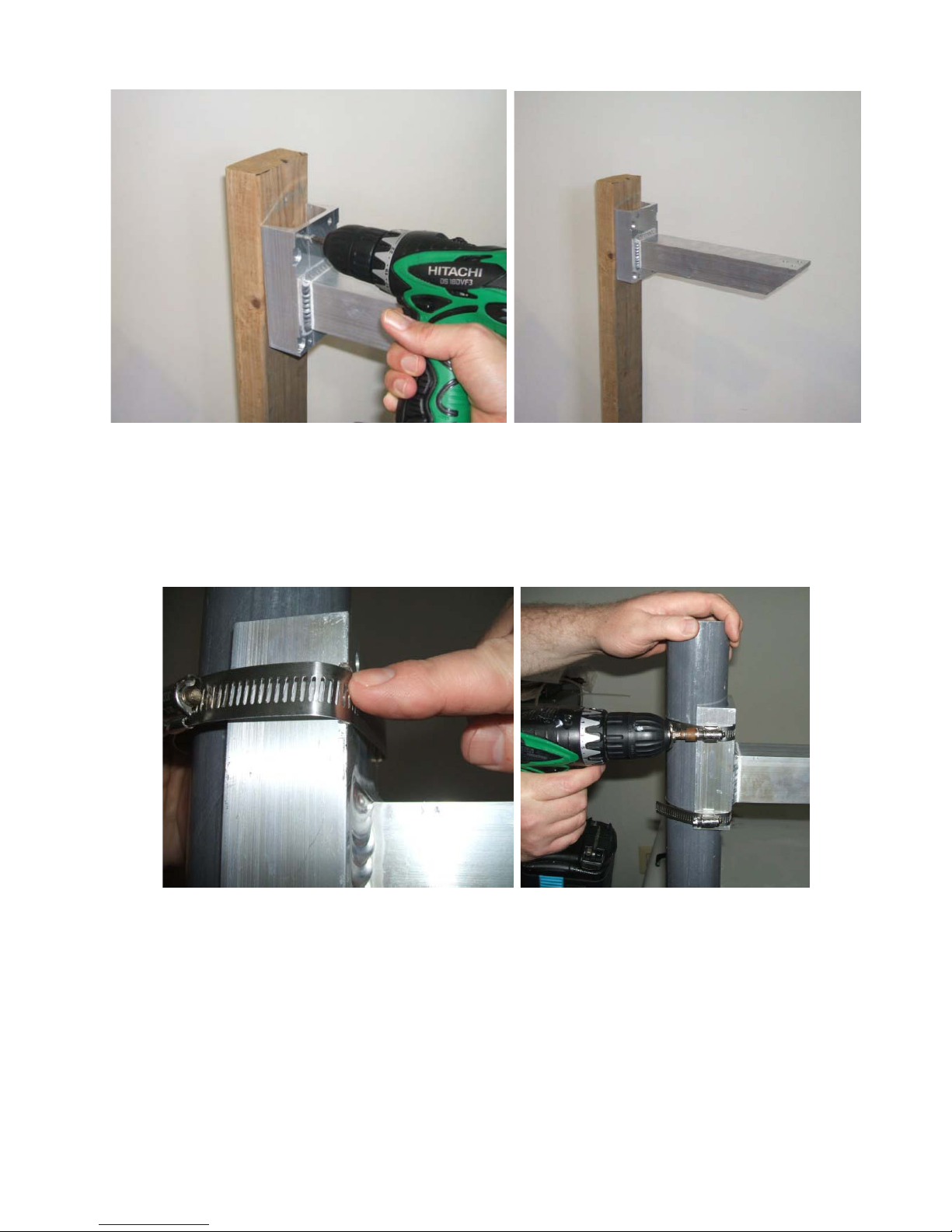
Figure 7: Attaching the Bracket to a Wall or Vertical Surface
To attach the mounting bracket to a pole, place and hold the bracket in the desired location. Take one of
the provided steel fastener straps from the kit and wrap it around the bracket base so that the steel band
lines up with the notched grooves on the edges of the bracket as shown in the figure below. Tighten the
steel fastener strap with a flat head screwdriver as shown.
Once the bracket has be en securely connected to a wall or pole, pull on it to make sure that it will hold
the weight of the pan tilt unit and camera. Next remove the bolts from the Pole Mount Bracket bag
provided in the kits along with the supplied Allen wrench. Place the pan tilt unit on top of the bracket
and align the pin on the shaft with the alignment hole in the bracket as seen in the figure below. Then
place a lock washer on each bolt and insert the bolts into the holes from underneath the bracket as shown.
Screw the bolts down with the Allen wrench until tight as seen below.
*It is recommended that this operation be done by two people or more. *
Figure 8: Attaching the Bracket to a Pole
8
Page 10
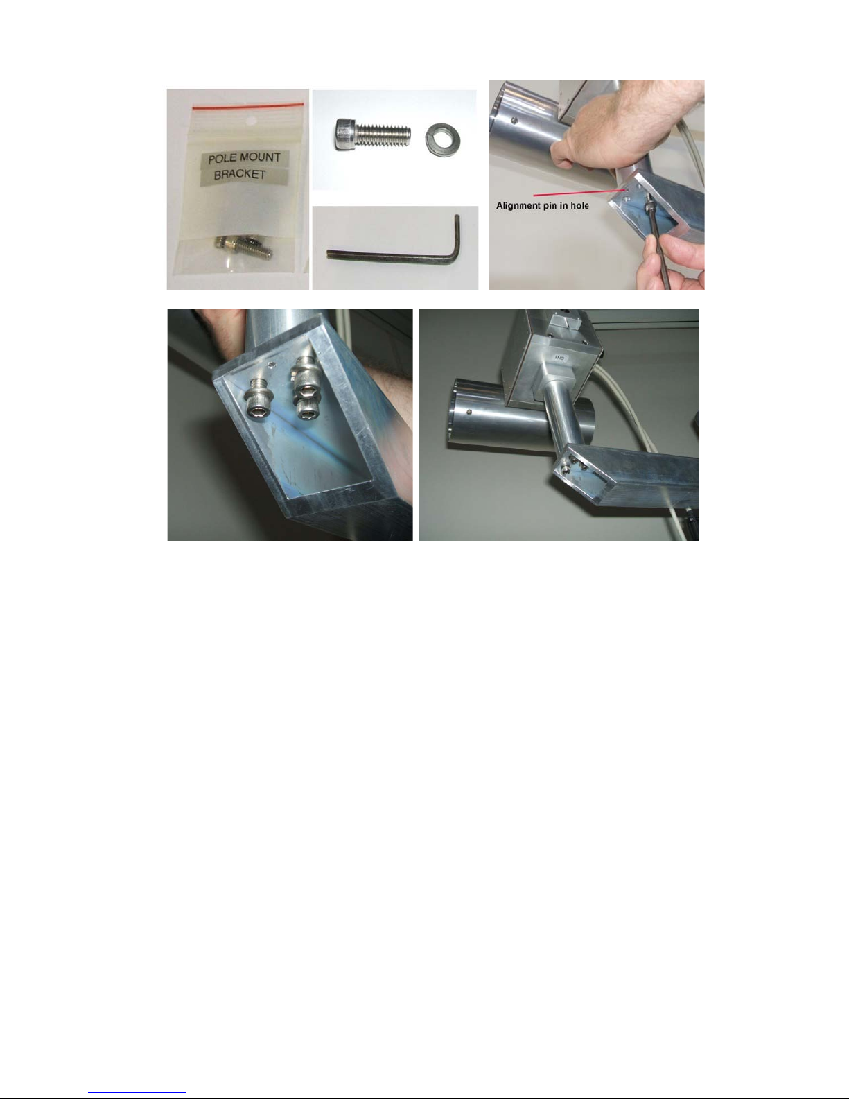
Figure 9: Attach Pan Tilt Unit to the Bracket
9
Page 11
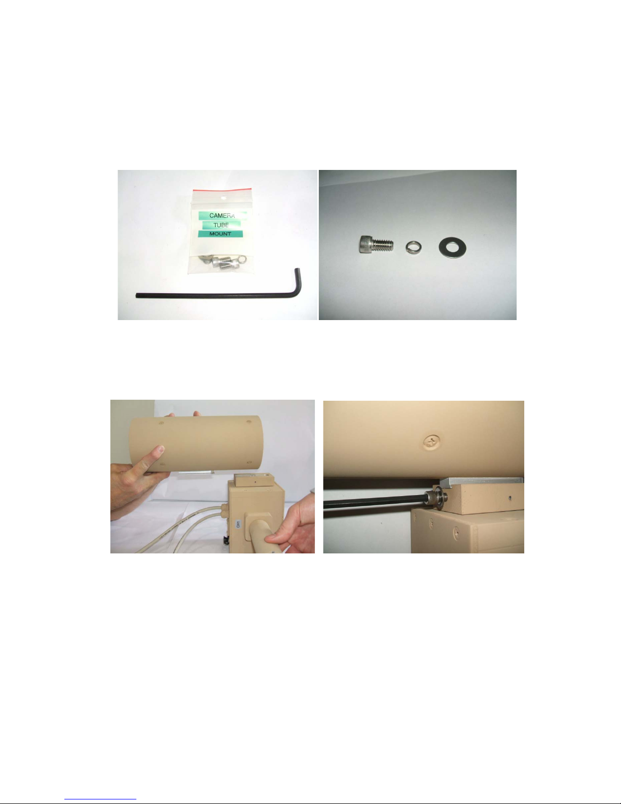
Connecting the Camera to the P an Tilt Unit
The cam era can be co nnected to t he Pan Tilt unit at any stage. In most cases it is recommended that the
brackets are mounted first then the pan tilt unit connected to the brackets and finally the camera
connected to the pan tilt unit, but the situation may require a different order of operation. To moun t the
camera to the pan tilt unit remove the camera tube and the Camera Tube Mount hardware bag from the
kit. Place a lock washer and then flat washer on a screw as shown in the figure below.
Figure 10: Camera Tube Mounting Hardware
Align the camera tube to the mounting bracket on the side of the pan tilt unit as shown in the figure
below. Take the screw, lock-washer, and flat washer assembly, and then insert it into the threaded hole
on the side of the pan tilt mounting block as shown in the figure below.
Figure 11: Attaching Camera Tube to Pan Tilt Unit
Connect the Camer a Tu b e cable to the Pan Tilt unit as shown in Figure 12. Align the notch on the cable’s
knurled metal ring with the black line on the green rubber strain relief. Align these with the notch on the
Pan Tilt unit’s connector. Gently but firmly push the cable connector into Pan Tilt unit connector. It
should slide in with moderate resistance. Tighten the metal ring until the connector clicks in place. When
fully tightened, the notch on the cable’s knurled metal ring should be 180 degrees from the notch in the
Pan Tilt unit connector. Repeat the same process for the Camera Tube.
NOTE: IT IS IMPORTANT THAT THE CAMERA TUBE CABLE IS FULLY TIGHTENED TO
PREVENT DAMAGE TO THE CABLE CONNECTORS.
10
Page 12
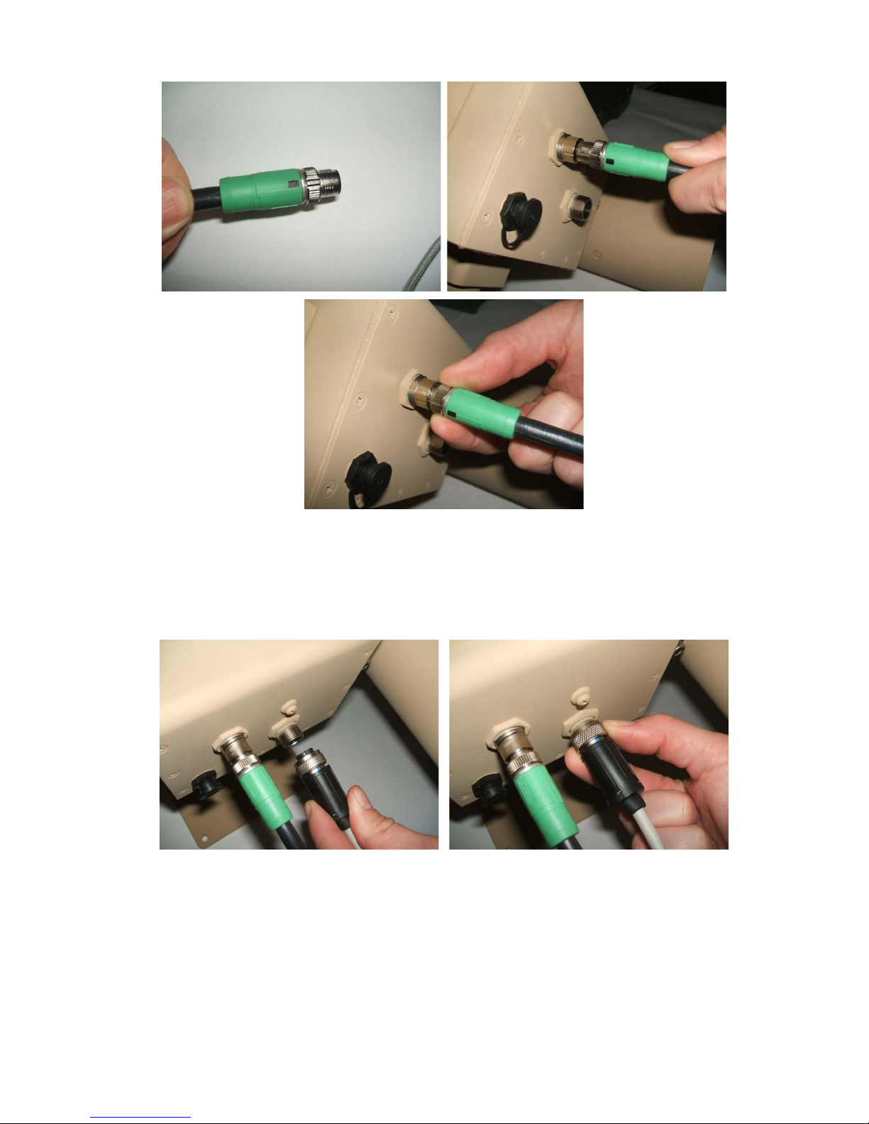
Figure 12: Attaching Camera Tube Cable to Pan Tilt U nit
Next connect th e Pan Tilt’s Power/Video/D ata Cable to the Pan Tilt unit as shown in E rror! Ref erence
source not found.. Make sure and align the connector so that the single notch is at the top and the two
notches are on the bottom to match the receptacle. Push the connector in and tighten the ring clockwise.
Figure 13: Attaching CAT-5 Cable to Pan Tilt Unit
11
Page 13
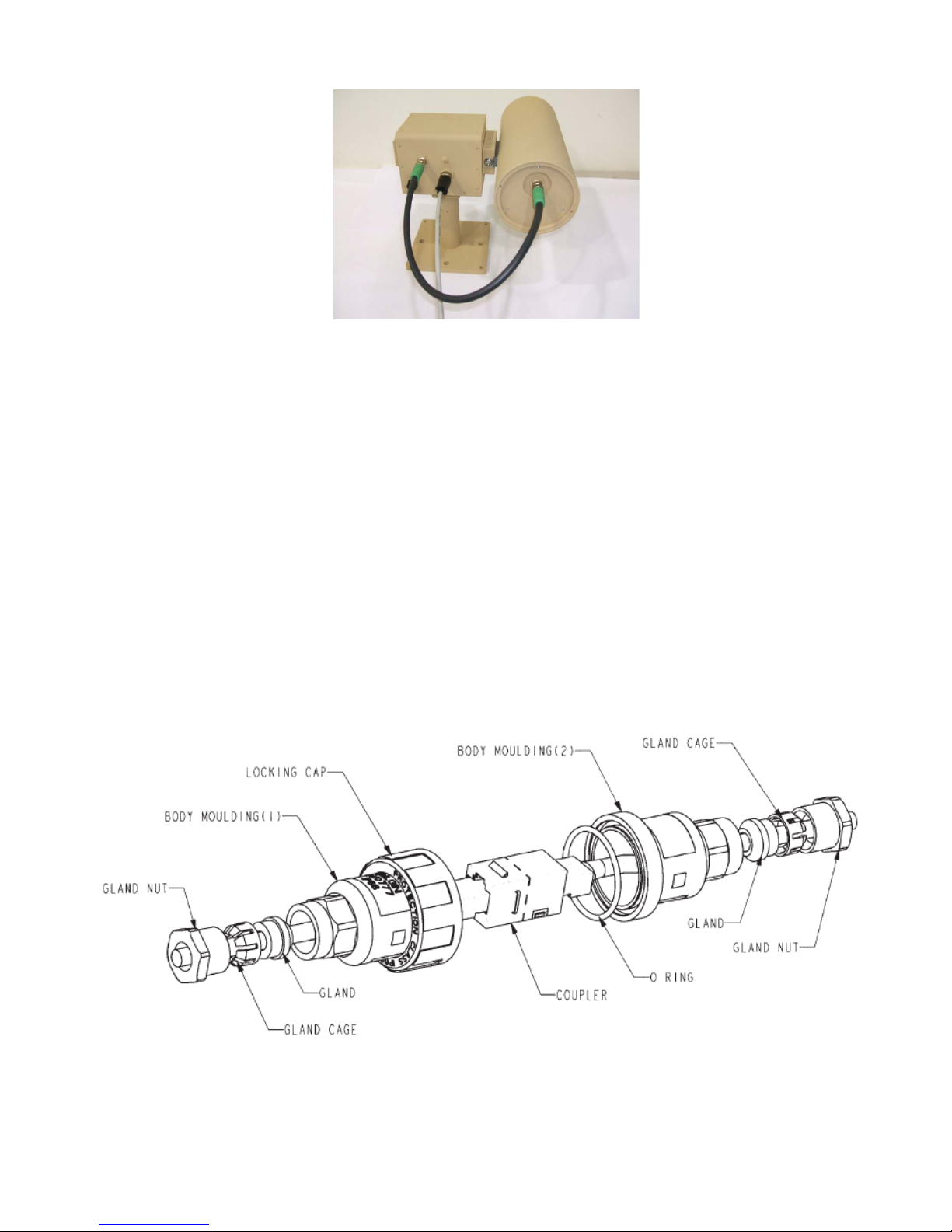
Figure 14: Assembled Pan Tilt Unit w i th Camera Tube
Terminating and connecting the CAT-5 Cable
The High P erforman ce Low Profile PTZ may be connected to the D OG B ase Stati on with up to 500m of
CAT-5 cable. The Base Station end of the cable can be terminated with a standard RJ-45 male connector.
The High Performance Low Profile PTZ end of the cable must be routed through the included
weatherproof conn ector prior to termination. An exploded view (with part labels) of the weatherproof
connector is shown in the figure below. Referring to Figure 16, unscrew the weatherproof connector
body molding from the High Performance Low Profile PTZ unit’s cable, route the end of the CAT-5
cable through the end of the body molding, and crimp on a male RJ-45 connector (not supplied).
**Make sure the cable passes through both the gland cage and the body molding.
Tighten the gland nut until the gland securely grips the cable, but do not over-tighten. Apply di-electric
grease to the RJ-45 contacts to reduce the risk of corrosion in extended use or environmentally harsh
installations. Connect the High Performance Low Pro file PTZ unit’s cable to the terminated cable using
the coupler. Slide the two body molding halves together and screw down the locking cap.
Figure 15: Weatherproof Connector Parts
12
Page 14
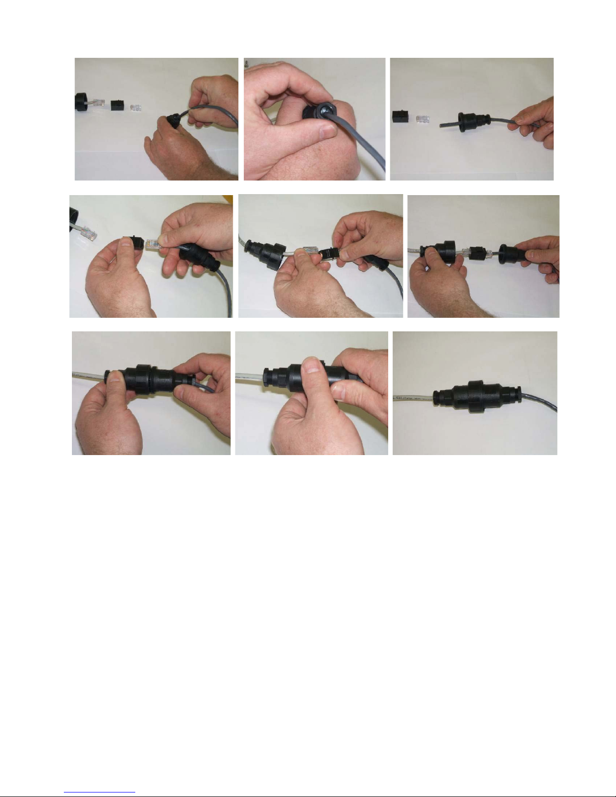
Figure 16: CAT-5 cable termination and c onnection
Once the CAT-5 c abl e is connected, use a wire tie (o r cord or tape) to s ecure the CAT-5 cab l e a gainst the
pole or mounting bracket for strain relief. Leave several feet of extra cable so the High Performance Low
Profile PTZ unit has enough slack to turn all the wa y. For a wall mount, the CAT-5 cable can be wiretied to the lower section of the mounting bracket itself. There should alwa ys be sufficient slack in the
cable for the unit to go through its full range of pan motion without the cable being caught or bound-up.
13
Page 15
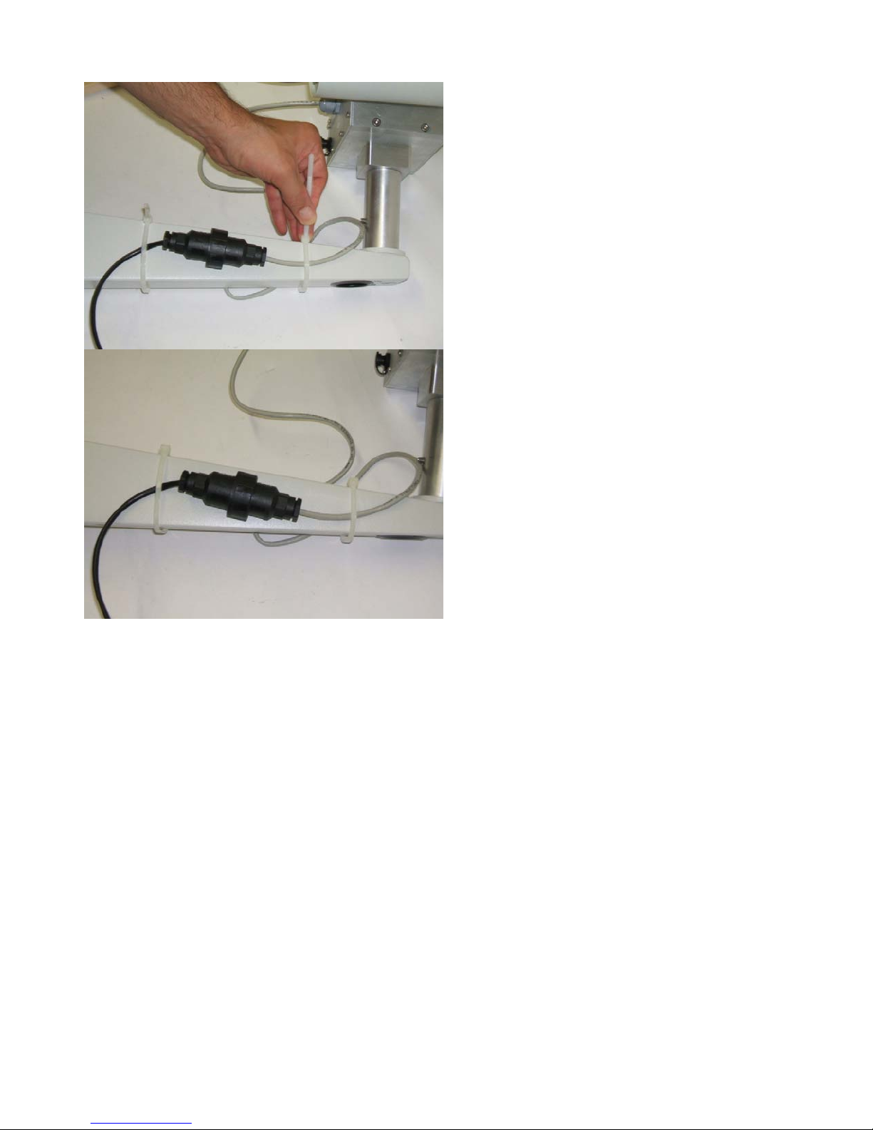
Figure 17: Strain Relief of the Cable
* Each mounted unit should be tested across its full range of motion while being directly
observed by a person to make sure that t here are no cable snags.
14
Page 16
Connecting the Thermal Camera and IR Illuminator
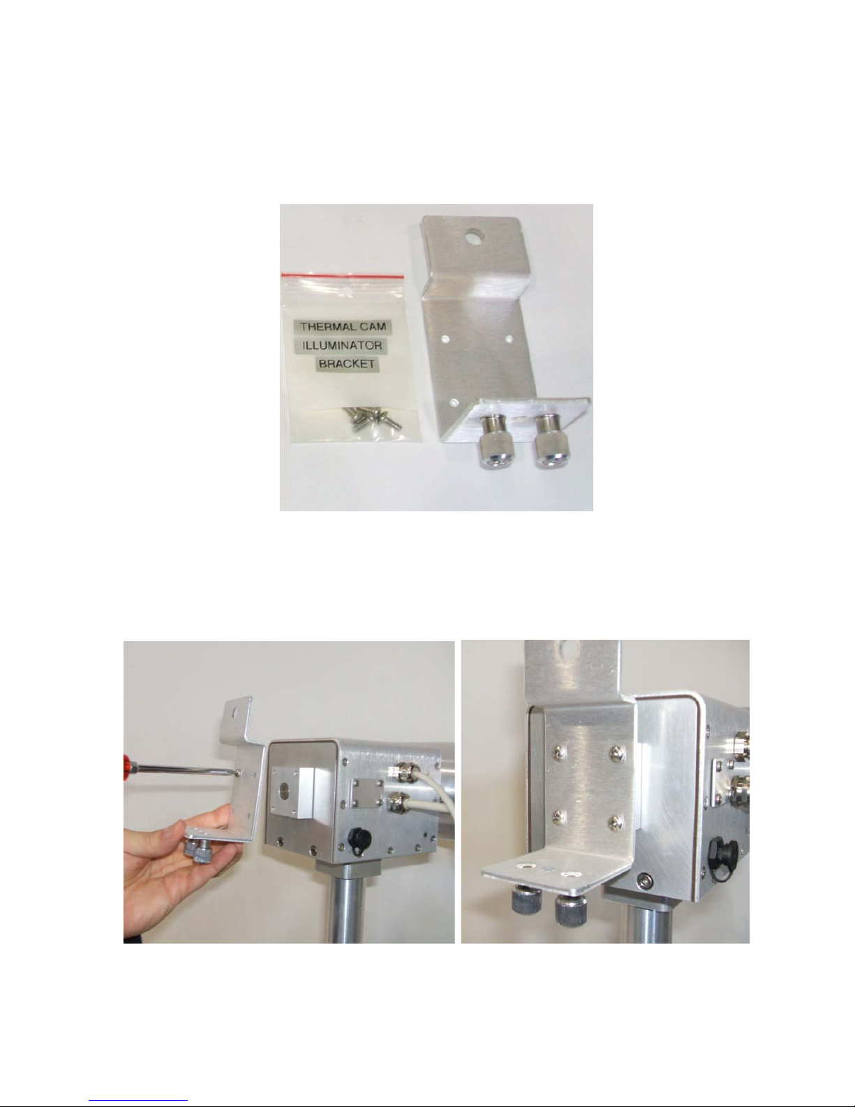
The PTZ accessor y bracket and mounting hardware shown in the figure below allow various accessories
such as the DOG t h ermal camera or DOG IR illuminator to be connected to the pan tilt unit. Remove the
hardware from the kit and obtain a Philips head screwdriver.
Figure 18: Camera Adapter Accessories
As shown in the figure below, align the bracket holes with the holes on the mounting block of the pan tilt
and screw in the four machine screws tightly. The unit is now ready to take accessories.
Figure 19: IR Illuminator/Thermal Camera Adapter Plate attachment
15
Page 17
Connecting the DOG IR Illuminator
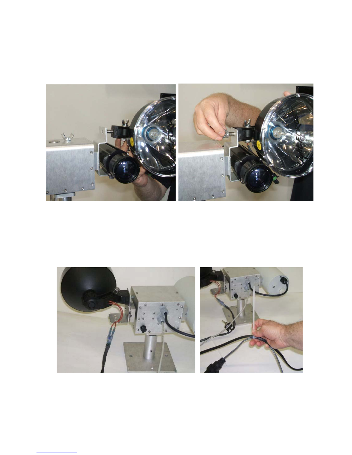
The IR Illuminator is a component from the DOG IR Illuminator Kit, which is available from S4-Tech.
Take an IR illuminator (with or without the IR filter installed) and remove the wind nut from the base
bolt. Push the bolt through the large upper hole on the accessory mounting bracket as shown in the figure
below. Then attach the wing nut and finger tighten onto the bracket.
Figure 20: Installing an IR Illuminator
Connecting the IR Illuminator Cable
The IR Illuminato r power cable is connected as seen in the figure below and des cribed in the DOG IR
Illuminator Kit User Manual. Once the cable has been connected, wire tie the two terminals from the
illuminator to the CAT-5 interface cable as shown below. Leave s everal feet of slack and wire tie the
cables to any solid object below the mounting bracket for strain relief.
Figure 21: Connecting the IR Illuminat or Power Cable
The strain relief should always be lower than the High Performance Low Profil e PTZ unit (6 inches to
several feet) and th ere should always be sufficie nt slack in the cables for t he unit to go through its full
range of pan motion without the cables being caught or bound-up.
16
Page 18
* Each mounted unit should be tested across its full range of motion while being directly
observed by a person to make sure that there are no cable snags.
**WHEN RE-PACKING
THE KIT, PRIOR TO POWER-DOWN, USE THE DVR DOME CONTROLS TO POSITION
THE TILT AXIS AT 0-DEGREES HORIZONTAL OR THE UNIT WILL NOT FIT**
***WARNING*** DO NOT LEAVE THE CA BLE HANGING FROM THE H IGH PERFORMANCE
LOW PROFILE PTZ UNIT WITHOUT STRAIN RELIEF.
Connecting the Thermal Ca m er a
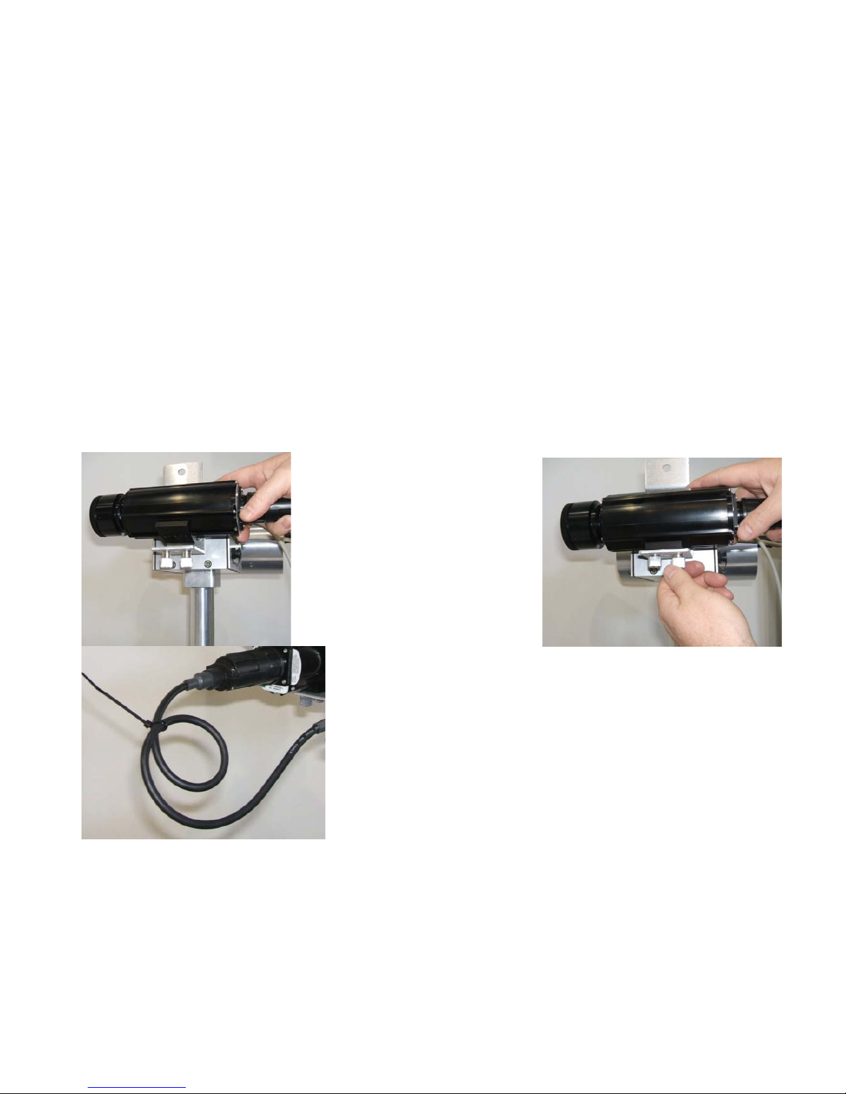
The Thermal Camera is part of the DOG Thermal Camera Kit available from S4-Tech. Remove a
thermal camera and connect the short 3 foot i nterface cable to t he ba ck of th e camera. Place t he cam era
over the bracket and align the holes on the bottom of the camera mounting base to the two thumbscrews
on the bottom of the bracket as shown in the figure below. Once the holes are aligned, tighten the thumb
screws as shown. Loop the camera i nteface cabl e a couple ti mes to take out some of t he slack and wire
tie the loop as shown in the figure below.
* Make sure to leav e enough slack so that the thermal camera can tilt ov er the full +/- 90 degree
range *
Take the connector at the end of th e cable and ali gn it with the thermal ca mera recepta cle on the b ack of
the pan tilt as shown in the figure below. Push the connector in and tighten by turning the ring at the
connector base clockwise. The thermal camera is now mounted and ready for operation.
Figure 22: Attaching a Thermal Camera
17
Page 19
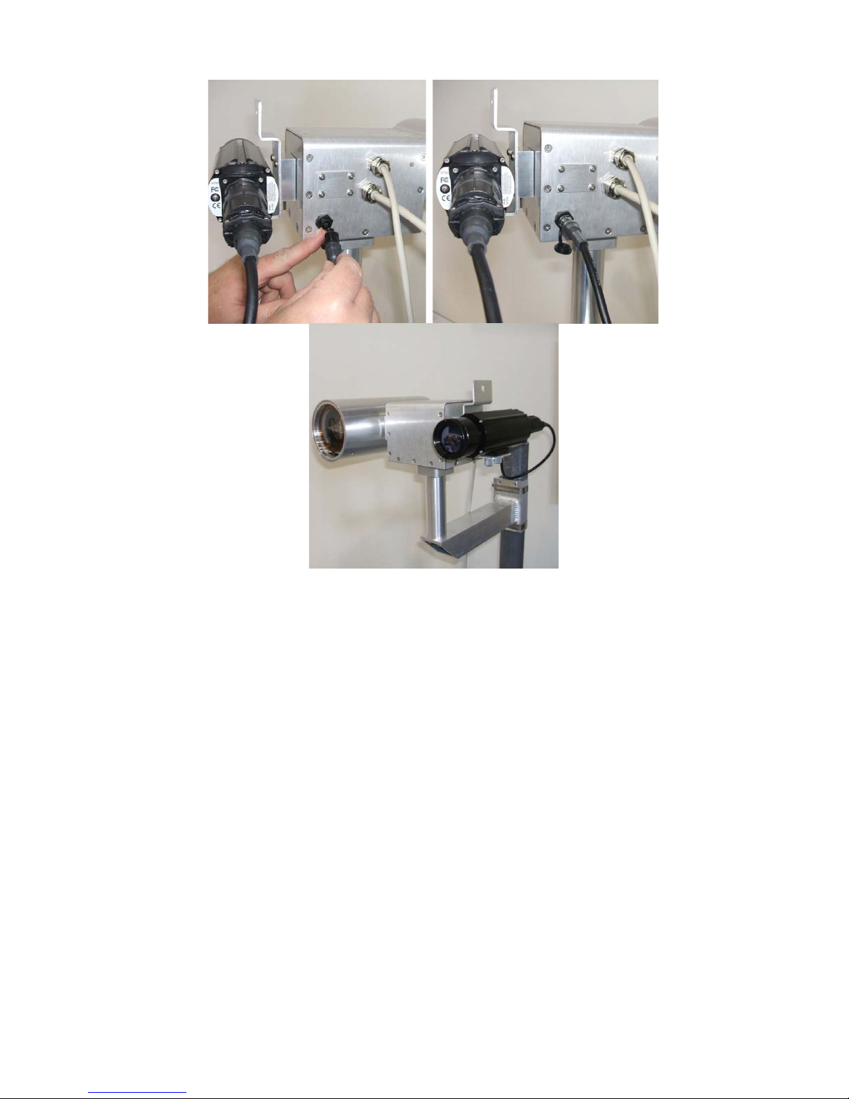
Figure 23: Connecting the Thermal Camera Cable to the High Performance Low Profile PTZ
Connecting PTZ Units to the Base Station
Connecting the High Performance Low Profile PTZ unit to the base station consists of three steps: (1)
connecting the High Perf ormance Low Profil e PTZ unit to the corresponding channel on the DOG Base
Station VPD using CAT-5 cables, (2) connectin g the VPD channels to the corresponding channels on the
Base Station DVR, and (3) connecting the PTZ port on the VPD with to the appropriate port on th e Base
Station DVR (depending on DOG version). The High Performance Low Profile P TZ unit channel IDs
are provided on a decal on the bottom of the unit as seen in Figure 3. The figure below shows the
described connections for a 4 channel DOG system. Even if only one or several High Performance Low
Profile PTZ units are employed, the channel numbers should always match the PTZ id numbers.
18
Page 20
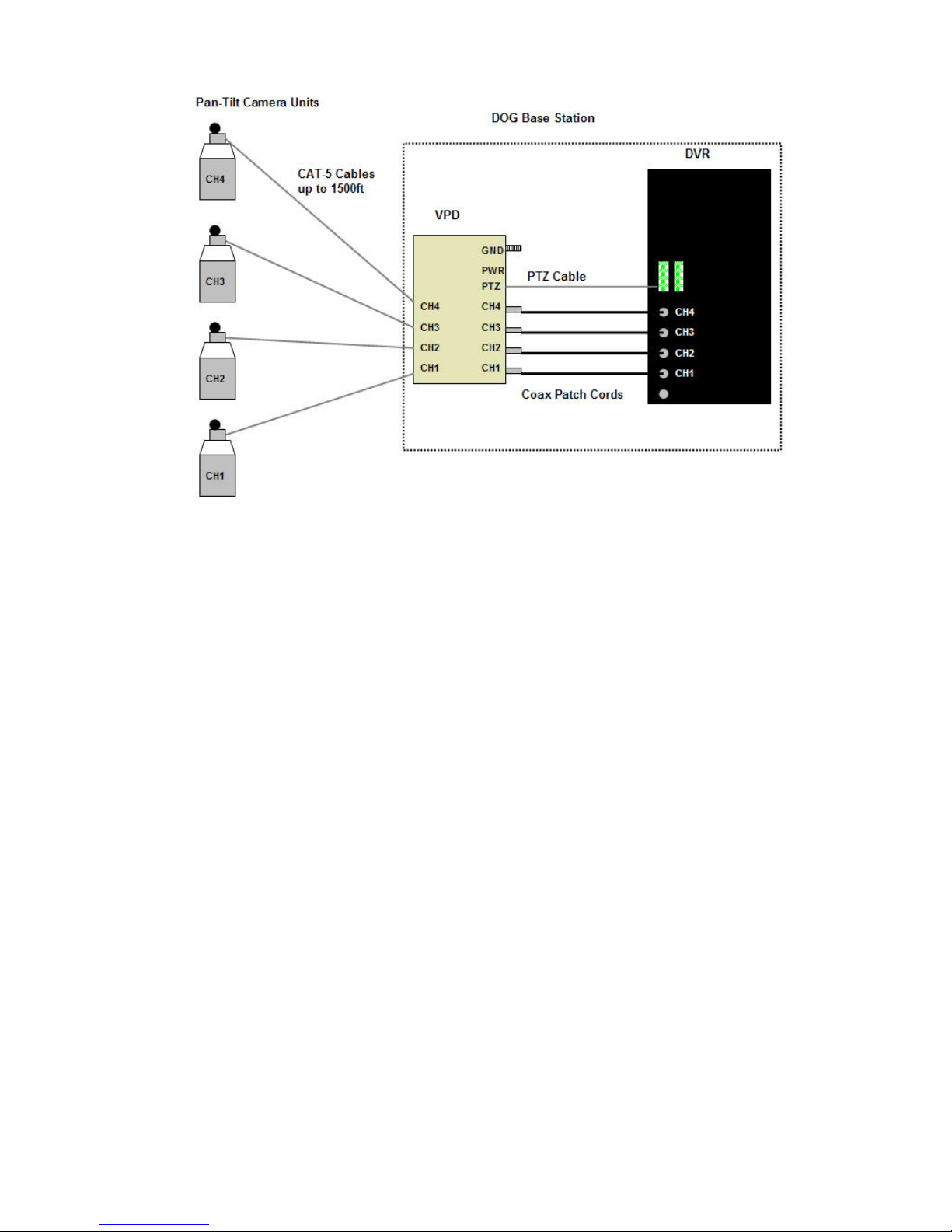
Figure 24: High Performance Low Profile PTZ Unit Connection Diagram
Note** An 8 channel DOG system would have Ch1 - Ch8.
19
Page 21

Troubleshooting
1. The High Performance Low Profile PTZ Unit stops during a motion.
• Let go and then push the arrow button again and the unit should resume movement.
• If panning, make sure the pan limit has not been reached by panning in the opposite
direction (push the other pan arrow button). Make sure there are no obstructions
physically preventing horizontal rotation of the High Performance Low Profile PTZ head.
• If tilting, make sure the tilt limit has not been reached by tilting in the opposite direction
(push the other tilt arrow button). Make sure there are no obstructions physically
preventing vertical rotation of the High Performance Low Profile PTZ head.
2. The High Performance Low Profile PTZ Unit does not move.
• Make sure that the s elected chann el matches t he High Performan ce Low Profil e PTZ unit
channel ID and that all connections to the VPD and DVR also match the channel number.
• Make sure that the supplied PTZ cable has been connected both on the VPD and the
terminal strips on the back of the DVR unit.
• Make sure that the red and black terminals of the PTZ cable are installed into the right
slots of the terminal block (red to D+ and black to D-).
• Make sure that High Performance Low Profile PTZ unit is plugged into the DOG Remote
Camera Unit through the side connector.
• Make sure the High Perf ormance Low Profi le P TZ software configuration is correct in the
DVR. See High Perform ance Low Profile P TZ Software Configuration Settings section of
this manual.
• If panning, make sure the pan limit has not been reached by panning in the opposite
direction (push the other pan arrow button). Make sure there are no obstructions
physically preventing horizontal rotation of the High Performance Low Profile PTZ head.
• If tilting, make sure the tilt limit has not been reached by tilting in the opposite direction
(push the other tilt arrow button). Make sure there are no obstructions physically
preventing vertical rotation of the High Performance Low Profile PTZ head.
3. The channel ID decal has come off and I don’t know the channel number of the Miniature
Pan-Tilt Unit. Plug the High P erform ance Low Profile P TZ Unit CAT-5 cable int o each ch annel
of the VPD and select each channel on th e DVR using the Dome Control function until the unit
responds. Mark the Miniature Pan-Tilt Unit with the correct Channel ID for reference.
4. The High Performance Low Profile PTZ video does not display on the monitor.
• Make sure that the vis ible camera is selected by pressing the DVR’s MODE button while in
Dome Control.
• Make sure that the coax patch cable is connected between the DVR and the VPD.
20
Page 22

Part No.
Description
DRP-PTZ
PTZ unit including pan-tilt head and camera.
DRP-PT
Pan tilt unit.
DRP-PTZ-CAM
PTZ camera.
DRP-CAM-STD
DOG standard camera module.
DRP-PT-BK-P
Pan-tilt kit pedestal bracket.
DRP-PT-BK-W
Pan-tilt kit wall/pole mount bracket.
DRP-PT-BK-DCAM
Pan-tilt kit DOG camera bracket.
DRP-PT-BK-IRI/T
Pan-tilt kit IR illuminator/thermal camera bracket.
DRP-PT-CASE
Pan-tilt kit rugged transport case.
Contact Info/Tech Support
For questions or support please see our website at: www.bcfsolutions.net or contact:
[email protected], 703-956-9088.
For user manual or other technical downloads go to the customer tab on the website and login with the
following: user: customer password: 2004-S4Tech
Replacement Parts
The following replacement parts may be ordered for the DOG High Performance Low Profile PTZ Kit.
Credit card orders are accepted. Please contact S4 for order information.
21
 Loading...