

Page 1
DIGITAL
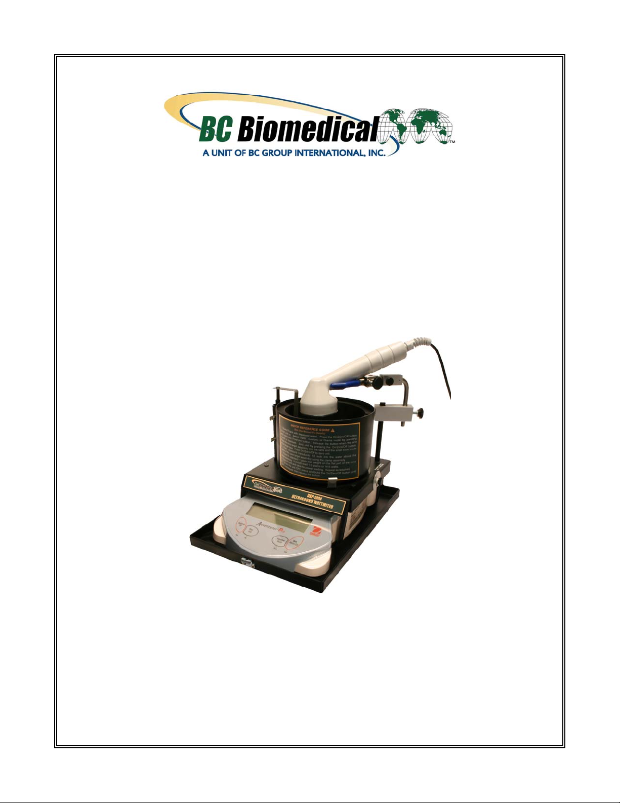
ULTRASOUND
WATTMETER
USP-100A
USER MANUAL
Page 2

Page 3

ULTRASOUND WATTMETER
Model USP-100A
TABLE OF CONTENTS
Introduction .............................................................................................................. 3
Unpacking the USP-100A ........................................................................................ 3
Replacement Parts .................................................................................................. 3
Selecting a Location for Operation .......................................................................... 4
Panel Controls and Display Indicator....................................................................... 4
Operating Procedure................................................................................................ 5
Transporting the USP-100A.....................................................................................6
General Operating Notes ......................................................................................... 6
Line/Battery Power...................................................................................... 6
Battery Installation....................................................................................... 6
Set Up ......................................................................................................... 7
Calibration ................................................................................................................ 7
Serial Computer/Printer Interface ............................................................................ 7
Programming Print Control ...................................................................................... 8
RS-232 ..................................................................................................................... 9
Output Formats ........................................................................................................ 10
Shipping Instructions for the USP-100A .................................................................. 11
Specifications ........................................................................................................... 12
Maintenance............................................................................................................. 13
Water, Tank Size, Transducer Placement & Temperature Considerations ............ 13
Ultrasound Radiation Levels .................................................................................... 14
Theory of Measuring Ultrasound Power With the Radiation Force Method ............ 15
Warranty................................................................................................................... 16
Sample Inspection Record (2 pages) .................................................................... 17
1
Page 4

NOTICE
BC GROUP INTERNATIONAL, INC. RESERVES THE RIGHT TO MAKE
CHANGES TO ITS PRODUCTS OR SPECIFICATIONS AT ANY TIME,
WITHOUT NOTICE, IN ORDER TO IMPROVE THE DESIGN OR
PERFORMANCE AND TO SUPPLY THE BEST POSSIBLE PRODUCT. THE
INFORMATION IN THIS MANUAL HAS BEEN CAREFULLY CHECKED
AND IS BELIEVED TO BE ACCURATE. HOWEVER, NO RESPONSIBILITY
IS ASSUMED FOR INACCURACIES.
CONTACT INFORMATION
BC BIOMEDICAL
BC GROUP INTERNATIONAL, INC.
PO BOX 25125
9415 GENTRY AVE
ST. LOUIS, MO 63125
USA
1-800-242-8428
314-638-3800
www.bcgroupintl.com
sales@bcgroupintl.com
Manual USP-100A Copyright © 2006
www.bcgroupintl.com
Made in the USA
10/06 Rev 02
2
Page 5

INTRODUCTION
Measurement of power output levels of diagnostic and therapeutic ultrasound equipment has become
increasingly important to determine exact patient exposure levels in case a potential risk exists to the
patient. Since the Radiation Control for Health & Safety Act of 1968 and the 1976 Medical Device
Amendments to the FDA Act became effective, all manufacturers of diagnostic Doppler ultrasound
equipment are required to submit information regarding their maximum peak and average exposure level,
beam patterns, and other pertinent information. Hospitals are responsible for regularly scheduled testing
(every six months) of output power and safety to maintain their accreditation.
The Ultrasound Wattmeter, Model USP-100A, is designed to measure the ultrasound power output of
diagnostic or therapeutic transducers up to 30 watts. The principle of measurement is the radiant force
method. The USP-100A uses a positioning clamp to hold the transducer in de-gassed water above a
conical target. The ultrasonic energy passes through the water to reflect off the target and is then
absorbed by the rubber lining. The radiant power is directly proportional to the total downward force
(weight) on the target. This weight is then transferred through the target support assembly to the electromechanical load cell inside the scale. The cell is in a computer-controlled feedback loop and produces a
digital readout in watts of power (custom units) or grams of force. The choice of units (grams or watts) is
selected by front panel pushbuttons. The USP-100A is supplied with a plug-in 120 VAC to 12VDC 400
mA adapter (using another adapter not rated the same may damage unit). The USP-100A has a display
resolution of ±200 milliwatts.
UNPACKING THE USP-100A
The power meter comes complete with all accessories in a sturdy carrying case. To make ultrasonic
measurements, the water tank requires only one pint of de-gassed distilled water. If de-gassed water is
not available, use distilled water, NOT tap water.
The following replacement parts can be ordered if necessary from BC Group :
REPLACEMENT PARTS
• Test Tank with Rubber
• Positioning Clamp Assembly
• Calibration Weight Standards
• 120 VAC to 12 VDC 500 mA power adapter
• PDF of User Manual available online at
www.bcgroupintl.com
• Carrying Case
3
Page 6

SELECTING A LOCATION FOR OPERATION
The USP-100A should always be used in an environment free from excessive air currents, corrosives,
vibration and temperature or humidity extremes. These factors will affect the displayed readings.
DO NOT operate the USP-100A:
• Next to open windows or doors causing drafts or rapid temperature changes
• Near air conditioning or heat ducts
• Near vibrating, rotating or reciprocating equipment
• Near magnetic fields or equipment that generate magnetic fields
• On an non level work surface
Allow sufficient space around the instrument for ease of operation and keep away from radiant heat
sources.
Never set any material on the USP-100A or place your hands or fingers on it while taking readings.
PANEL CONTROLS & DISPLAY INDICATOR
1. On/Zero/Off - Yes button; Press to turn unit on or zero, press and hold until OFF is displayed then
release to turn off.
2. Print/Unit - No button; Press to print, press and hold then release when unit desired is displayed.
3. Function/Mode - Back button
4. Tare/Menu-Cal - Exit button; Press to tare
5. 7 - segment display; Shows readings. A “g” after the reading indicates grams.
6. Stability Indicator
7. Net Indicator
8. 14 - segment display; Shows units, Custom is watts.
9. Symbols for weighing units are:
Grams Mode
Custom Mode
x.xx x.x
4
Page 7

OPERATING PROCEDURE
1. Remove the top of the carrying case by unlatching the clamps located on two ends.
The USP-100A is mounted on the base of the carrying case.
2. Place the USP-100A on a stable and level surface. Avoid air currents and mechanical
vibrations. Level unit as much as possible.
3. Loosen the positioning clamp and position out of the way, remove cone target from the
clips on the table tube and test tank where it is normally stored. Tank is positioned on the rubber
circle.
4. Fill the test tank to ¼ inch below the top of the rubber liner with recently de-gassed water
at room temperature. (To obtain de-gassed water, boil distilled water for 20 minutes, fill a jar
completely, cover, and allow to cool).
5. Plug the AC Adapter into a 120 VAC, 60 Hz power outlet and plug it into the power jack
at the rear of the unit. Depress the On/Zero/Off button.
6. Lower the cone target into the concentric target support sleeve located to the back/left of
the test tank (small tube inside of larger tube ), while simultaneously placing the cone target into
the tank. If the cone can swing in an arc, it is not down far enough. Tip the rod back and forth
slightly to fully engage the rod. Press the On/Zero/Off button.
7. By means of the positioning clamp, attach the transducer head and place its radiating face 1/8”
to 1/4” inch below the water level, parallel to the water surface, and directly above the center of
the cone. Check transducer surface for uniform wetting (no air pocket or bubbles should be on
its surface).
8. Allow 5 minutes for the scale to stabilize. With no ultrasonic power applied to the transducer,
press the On/Zero/Off button to zero the unit.
9. Check response by placing the 1 gram weight on the arm of the cone target (the flat part that is
out of the water). The USP-100A should read 1.00 grams ± 0.1. Change the units to the watts
mode by pressing and holding the Print/Unit button until the unit desired is displayed then
release. The USP-100A should read 14.6 watts ± 0.2 watts. 1 gram is equal to 14.6 watts.
10. Remove the 1 gram weight. Press the ON/Zero/Off button to zero the unit.
11. Apply power to the Transducer Under Test (TUT). Re-zero before each measurement and take
your power reading when the display has stabilized. It is a good practice to take three readings
and average them. If measurement conditions are not stable, use the grams mode and multiply
the readings by 14.65 to obtain watts.
12. Determine the maximum peak power with the maximum duty cycle and pulsed output settings
with the equation:
PAVE = Pp ÷ Rtpa
PAVE = calculated average power
Pp = Peak Pulsed Power Setting on unit under test
Rtpa = Ratio of Temporal Peak to Average Power
(from each manufacturer)
13. To calculate the watts/cm
area. The area is
πd
2
output, take the total watts reading from the unit and divide by the
2
÷ 4 (d is the diameter of the transducer) if the transducer is smaller than
the cone. Otherwise, use (8.2 cm) the cone’s diameter as the area.
14. When finished, unplug the USP-100A, empty the tank, and place the dry target cone in the tank
for protection.
5
Page 8

TRANSPORTING THE USP-100A
Lift off the target cone assembly from the sleeve, empty water into a storage container, dry the tank and
cone, place cone in the tank and clamp the target rod into the storage clips on the side of the target
sleeve. Place the power supply in the tank. Rotate the transducer clamp arm over the top of the tank and
stretch the large rubber band between the two hooks of the hold-down clip, over the clamp arm and tank.
Place the carrying case cover over the base and secure the latches.
(For shipping instructions see Page 11).
GENERAL OPERATING NOTES
Line / Battery Power
The USP-100A is supplied with a 120 VAC adapter. Check for correct line voltage before use. For
voltages 220/240 VAC, an optional power adapter can be ordered from BC Group.
1. Slowly fill tank with degassed water. Press the On/Zero/Off button to turn unit on. Select
Watts(custom) or Grams by pressing and holding the Print/Unit button. Release the button when
unit needed is displayed. Press the On/Zero/Off button to zero unit. Place cone target assembly
into test tank and in the small tube inside of the large tube. Press the On/Zero/Off button to zero
the unit.
2. Place ultrasound transducer 1/8 inch into water above the center of the cone target using the
clamp assembly.
3. Place the standard 1 gram test weight on the flat part of the cone target assembly. It should read
1.0000 (1.000) grams or 14.650 (14.65) watts.
4. Zero the unit and take the power reading. Repeat as required.
5. To turn unit off press and hold On/Zero/Off until OFF is display, then release.
Battery Installation: (Battery operation optional)
1. Remove tank, target, and clamp assembly. Remove tabletop from base leaving the standoffs
connected to the tabletop.
2. Tilt base of unit over enough to enable removal of rubber feet with a screwdriver.
Be careful not to allow unit to rest on target support sleeve!
3. Remove balance from the base, and position it to allow access to battery compartment.
Again, be careful of the target support sleeve!
4. Remove compartment cover and install 4 AA alkaline batteries in the battery holder,
observing orientation marks. Replace the battery holder and compartment cover, and
reassemble unit. Be careful not to damage the target support sleeve.
:
6
Page 9

Set Up:
If you accidentally get into the Setup menu, you can get out by pushing the Tare/Menu-Cal - Exit button.
The USP-100A Ultrasound Power Meter is a custom programmed balance with additional hardware (cone
target, tank, etc.) designed to provide ultrasound power readings. Entry into the Setup menu enables the
user to modify certain parameters, allowing the unit to perform additional useful functions. These
functions are described in the pages that follow. Critical programming such as calibration and Custom
mode parameters are locked in and cannot be changed by the user. If reprogramming to the original
parameters does become necessary, the unit must be returned to BC Group’s facility. An hourly labor
rate will be charged for any necessary repairs and recalibration fees will be assessed. A calibration
certificate will be returned with the unit.
CALIBRATION
A 1-gram weight is supplied to check the calibration and programming. With the transducer under test
turned off, zero the unit. Place the weight on the arm of the cone target. Within 3 seconds the unit should
read 14.6 watts (± .2 watts) or 1.0 grams (± .01 grams). If this reading is significantly off, the USP-100A
needs to be recalibrated. Send it to BC Group for calibration. It is recommended that the USP-100A be
returned to BC Group on a yearly basis for calibration and certification.
SERIAL COMPUTER/PRINTER INTERFACE
The USP-100A is equipped with a bi-directional RS-232 compatible interface for communication with
printers and computers. When the balance is connected directly to a printer, displayed data can be output
at any time by simply pressing the PRINT/Unit button or by using the Auto Print feature. Connecting the
balance to a computer enables you to operate the balance from the computer, as well as receive data.
A BC Biomedical RS-232 cable is required to enable the balance to communicate with a computer or
printer; a standard RS-232 cable will not work. The cable can be ordered from BC Group. Cable part
numbers are as follows: 25-pin: # 80500524; 9-pin: #80500525
IMPORTANT
External PRINT and/or TARE switches may be installed
as shown in the diagram.
Momentary contact switches must be used.
7
Page 10

PROGRAMMING PRINT CONTROL
The Print-1 submenu is used to set printing parameters for an external printer or computer.
Output
Set When Stable to On to print only when stable values.
Set When Stable to Off to print stable or unstable values.
Set GLP Tare to On to print GLP data once after a tare operation.
Set GLP Tare to Off to disable this feature.
Auto Print
When set to Continuous, the displayed value is printed continuously.
When set to Interval, the displayed value is printed at the user specified time interval
If set to When Stable, the balance will automatically print the display when stability is achieved.
An additional setting must be made to determine if only stable non - zero values will be printed
When set to Off, the Auto print feature is disabled.
Content
All of these features can be set On or Off:
Layout
Determines the format of data output to a printer or computer.
If Line Format is set to Multi, a multi-line printout is generated.
If it is set to Single a single line printout is generated.
If 4LF is set to Yes, 4 line feeds are appended to the printout.
If Form feed is set to Yes, a form feed is appended to the printout.
List
When Yes is selected, a printout of balance settings is printed
End Print - 1
Press the On/Zero/Off - Yes button to advance to the next menu.
Pressing the Print/Unit - No button returns to output Menu item.
When set Off, entries may be changed. Off is the default setting.
(1 to 3600 seconds).
(Load & Zero).
Numeric data only, Header, Gross, Net, Tare, Reference, Result, GLP.
This is useful for printing to page printers.
.
8
Page 11

RS-232
The RS-232-1 submenu is used to set communication parameters for an external printer or computer.
Power
This menu item allows setting the Power On or Off for COM1.
When the balance is operated from the AC Adapter, this menu is hidden and the setting is On.
When the balance is operated from batteries, the menu item is available and the default setting is Off.
To enable COM1, Power must be turned On.
Baud
Rates of 60,1200, 2400, 4800, 9600, and 19,200 are available.
Parity
Parity settings of 7 even, 7 odd, 7 No Parity, and 8 No Parity are available.
Handshake
Settings of Off, XONXOFF and Hardware are available.
End RS1
Pressing the On/Zero/Off - Yes button will advance to the GLP submenu.
Pressing the Print/Unit - No button returns to the Power (or baud) menu item.
9
Page 12

OUTPUT FORMATS
Commands listed in the following table are acknowledged by the balance. The balance will return “ES” for
invalid commands sent to the balance.
Command Function
IP
P
CP
SP
SLP
SLZP
xP
H
Z
T
xT
PT
PM
M
Immediate Print of displayed weight (stable or unstable).
Print displayed weight (stable or unstable).
Continuous Print.
Print displayed stable weight.
Auto Print stable non-zero displayed weight.
Auto Print stable non-zero weight and stable zero reading.
Interval Print x = Print Interval (1-3600 seconds).
Enter Print Header Lines
Same as pressing Zero key.
Same as pressing Tare key.
Establish a preset Tare value in grams. x = PRESET TARE VALUE IN GRAMS.
Prints Tare weight stored in memory.
Print current mode (weighing mode).
Scroll to the next enabled mode.
PU
U
OFF
PSN
PV
Print current weighing unit.
Scroll to the next enabled unit.
Turns balance OFF.
Print Serial Number.
Print Version: name, software revision and LFT ON (if LFT is set ON).
10
Page 13

SHIPPING INSTRUCTIONS FOR THE USP-100A
To make certain that your Ultrasound Power Meter arrives at our repair department unharmed during
shipment, please follow these instructions:
1. Empty water from tank and dry.
2. Wrap the target cone in a protective covering and place in tank; do not put target support
bracket in the tabletop tube nor in the clips (if tank should move during shipment, the bracket
will be damaged).
3. Place the weight under the screw provided. Make sure the transducer clamp assembly is
screwed in place tightly over the tank and pull the large rubber band over the tank and clamp.
4. Fasten the case lid onto the base, after making certain there is nothing loose inside.
5. The package used for shipping should be strong and large enough to allow for adequate packing
material on all sides of unit.
6. Ship to:
BC Group Instruments Company
9514 Gentry Avenue
St. Louis, Missouri USA 63125
8. Enclose paperwork (packing slip, purchase order form, letterhead) which includes your return
address, contact name and telephone number. A description of the work that needs to be done
would be helpful.
By using the above instructions you will avoid additional charges which can be incurred if the unit is not
packaged well enough to withstand rough handling during shipment.
Neither BC Group nor the shipping company can be held responsible for damage
if these instructions are not followed.
11
Page 14

SPECIFICATIONS FOR THE USP-100A
r
Power Range
0 to 30 Watts
Resolution
Minimum Detectable Power
Display Sensitivity
Accuracy
Stabilization
Maximum Weight Capacity
Maximum Transducer Size
Transducer Operating Frequency
Test Media
Computer Interface
Default Baud Rate
Power
120 VAC Adapter Supplied (Adapters fo
240 VAC available on special order)
EMI Rating
Battery
Electrical Safety
±200 mW
±200 mW
0.2 Watt
±3% + One Count
2.5 Second Integration
410 Grams
3” Diameter
0.5 to 10 MHz
Degassed Water
RS-232, 600-19200 Baud
2400
12 VDC, 500 mA
120 VAC to 12 VDC w/ 2-Conductor Plug and
6-Ft. Cord
Conforms to CE & FCC
4 AA (not included)
Conforms to UL, CE & CSA
Size
Weight
Carrying Case
8.5” x 12” x 8.75” (H x L x W)
11 Lbs. Net
Black Anodized Aluminum
12
Page 15

MAINTENANCE
Verification of Proper Scale Functioning
Small variations of water surface motion, air currents or mechanical movements may cause uncertainties
in power measurements. To test scale accuracy at low levels, set up the scale as in the Operating
Procedure (Page 4). Place the 14.6 watt weight on the flat surface of the target arm. Read meter three
times; readings should be within ± .2 counts (for example, 14.4 to 14.8). In case of doubt about lower
power resolution, repeat the same procedure using light objects such as thin paper slices to produce
readings of 5 to 10 counts; repeat readings. Average uncertainty should be within ± .2 counts on the
watts scale. Avoid mechanical and air movement or variations in magnetic fields while making tests.
Out of Measurement Range Warnings
Model USP-100A accommodates weight differential of ± 410 grams. When the scale exceeds this range,
“Error 8.3” will be displayed. Something may be pressing hard on the target or support. “Error 8.4”
indicates underweight condition. If no obvious error has been made by the user the unit should be
returned for service when any code is displayed.
No Display
1.
2.
3.
WATER, TANK SIZE, TRANSDUCER PLACEMENT & TEMPERATURE CONSIDERATIONS
Water as a Measurement Medium
The measurements are to be performed in de-gassed water because ultrasound propagation in water
closely approximates that in tissues (see UL-1-1981, AIUM/NEMA Standard Publication). The ultrasonic
attenuation in water can be taken as a lower limit on the attenuation which will be encountered in the
body. Large areas in the body can consist of low attenuating material such as urine and amniotic fluid.
The use of water prevents measurements in a more highly attenuating material such as liver equivalent
gels from representing the highest possible intensities which might be encountered in the body. A
measurement temperature of 24°C ± 3°C (75°F ± 5°) is chosen for convenience.
De-Gassed Water
Ultrasound power measurement accuracy is affected (by lowering the power reading) if the water
contains more than five parts per million of air. To de-gas, boil distilled water for 20 minutes, then pour
into a suitable container, seal tightly and place in refrigerator. This process will give the required quality.
The container should be heat resistant glass, or thick plastic may be used after the water has been
cooled. Before testing, pour water into tilted test tank to minimize turbulence. The test tank water surface
will absorb oxygen and a change of de-gassed water is recommended before each test. An alternative
method of de-gassing water is to heat the water to boiling, then pull a vacuum for five minutes.
Water temperature affects accuracy; use a testing temperature of 21 to 27°C ambient. Sonic energy
agitates the water surface through heating and scattering. Testing time should be limited to a few
minutes; prolonged testing, particularly at higher power levels, will drive out dissolved air and air bubbles
will be visible on surfaces in the tank. These bubbles can be gently brushed off.
:
Make sure the AC adapter’s plug is fully seated in the jack at the back of the unit.
Use a voltmeter to verify the adapter is producing 12 volts DC (approximately).
Call our service department for assistance.
:
:
:
:
13
Page 16

Transducer Wetting and Placement:
After tilting the transducer into the water at a 45° angle, verify that the surface is uniformly wetted. The
transducer should be positioned above the cone target. Small variations will occur due to placement. Try
various positions above target to obtain a maximum power reading.
ULTRASOUND RADIATION LEVELS
There are no maximum limits in the U.S. for therapy power
accuracy to ± 20% of actual output is required. Exposure levels for physical therapy applicator heads
range from 100mW/cm
area in cm
from FDA Section 510(k) guidance to manufacturers on submissions and clearance as of February 1993.
Refer to the AIUM and FDA publications for complete and up to date testing standards and
interpretations. Measurements are done in all standard modes of operation. Power intensity is rated as
Spatial Peak Temporal Average (I
are derated for tissue and in parenthesis for the water medium (use this chart):
2
. The power limits shown in the following table for diagnostic ultrasound have been extracted
2
to 3W/cm2. Total power requires multiplication by the radiated cross sectional
, only the verification of the displayed setting
) and Spatial Peak Pulse Average (I
SPTA
). The values in mW/cm
SPPA
2
PRE-AMENDMENT ACOUSTIC OUTPUT LIMITS
Use
Peripheral Vessel
Cardiac
Fetal Imaging & Other * 94
Ophthalmic
* Abdominal, intra-operative, pediatric, small organ (breast, thyroid, testes, etc.),
I
Tissue (mW/cm2) Water I
SPTA
720
430
17
neonatal cephalic, adult cephalic.
1500
730
180
68
Tissue (mW/cm2) Water
SPPA
190
190
190
28
350
350
350
110
14
Page 17

THEORY OF MEASURING ULTRASOUND POWER WITH THE RADIATION FORCE METHOD
Sound is a form of energy that sets the particles in the isonated medium into vibrational motion. The
particles then possess a kinetic energy. If dP
is the rate of the flow of this energy about an area dA,
m
then the mean acoustic energy is:
Eq. 1 I = dP
/dA I = Acoustic intensity at a point in that area, Watts/cm
m
2
When a plane sound wave propagates through a uniform non-absorbent medium, the intensity must be
the same for all points in the wave. Let E represent the energy density, i.e., the energy per unit volume.
When the sound energy passes through a unit cross-sectional area with a speed c, the intensity is:
Eq. 2 I = cE E = Energy density per unit volume, ergs/cm
c = Ultrasound wave velocity, cm/sec
3
The radiation pressure effect can be explained by analogy to the application of an alternating electric
voltage to a non-linear load. With the non-linear load it appears that both AC and DC components are
present. In ultrasonics the non-linear element is the density of the fluid and hence acoustic impedance
(load) varies in the same periodical manner as the density. Therefore in ultrasound the two components
of pressure, one alternating and the other direct are present. The average AC pressure per cycle is zero,
but the DC pressure of radiation is:
Eq. 3 Pτ = I/C Pτ = Pressure of Radiation, ergs/cm
3
Therefore, from the above two equations, the pressure of radiation (Pτ) is equal to the energy density (E).
Eq. 4 Pτ = E
It is this DC pressure of radiation that can be measured. At low frequencies, below 100 KHz, a standard
high frequency hydrophone can be used. For higher frequencies, generally used in medical applications,
1-15 MHz, hydrophones are not available. At these frequencies the force can be measured using a
precision balance and a radiation force target that is perfectly absorptive. The conversion from force to
power can be accomplished using the equation:
Eq. 5 p = Wgc W = measured force, grams
g = acceleration, dynes
c = velocity of ultrasound, cm/sec
p = power, ergs/sec
By combining all constants together and converting from ergs/sec to watts, we obtain a simplified
equation that is used to calculate the ultrasonic power once the force is measured:
P = w(14.65) P = Ultrasonic power in watts
w = Ultrasonic force in grams
To determine the ultrasonic watt density (watts/cm
2
or watts/in2) of a given transducer the P is divided by
the cross sectional area of the transducer.
15
Page 18

LIMITED WARRANTY
A
A
WARRANTY: BC GROUP INTERNATIONAL, INC. WARRANTS ITS NEW PRODUCTS TO BE FREE FROM
DEFECTS IN MATERIALS AND WORKMANSHIP UNDER THE SERVICE FOR WHICH THEY ARE INTENDED.
THIS WARRANTY IS EFFECTIVE FOR TWELVE MONTHS FROM THE DATE OF SHIPMENT.
EXCLUSIONS: THIS WARRANTY IS IN LIEU OF ANY OTHER WARRANTY EXPRESSED OR IMPLIED,
INCLUDING, BUT NOT LIMITED TO ANY IMPLIED WARRANTY OF MERCHANTABILITY OR FITNESS FOR
PARTICULAR PURPOSE.
BC GROUP INTERNATIONAL, INC. IS NOT LIABLE FOR ANY INCIDENTAL OR CONSEQUENTIAL
DAMAGES.
NO PERSON OTHER THAN AN OFFICER IS AUTHORIZED TO GIVE ANY OTHER WARRANTY OR ASSUME
NY LIABILITY.
REMEDIES: THE PURCHASER'S SOLE AND EXCLUSIVE REMEDY SHALL BE: (1) THE REPAIR OR
REPLACEMENT OF DEFECTIVE PARTS OR PRODUCTS, WITHOUT CHARGE. (2) AT THE OPTION OF BC
GROUP INTERNATIONAL, INC., THE REFUND OF THE PURCHASE PRICE.
IF ANY FAILURE OCCURS, THE FOLLOWING STEPS SHOULD BE TAKEN:
Notify BC Group, giving full details of the difficulty, and include the model, type, and serial numbers (where
applicable). On receipt of this information, service data, or shipping instructions will be forwarded to you.
Upon receipt of shipping instructions, forward the instrument, transportation prepaid. Repairs will be made
and the instrument returned, transportation prepaid.
SHIPPING TO MANUFACTURER FOR REPAIR OR ADJUSTMENT
All shipments of BC Group instruments should be made via Federal Express or "Best Way" prepaid. The
instrument should be shipped in the original packing carton, or if it is not available, use any suitable
container that is rigid and of adequate size. If a substitute container is used, the instrument should be
wrapped in packing material and surrounded with at least four inches of excelsior or similar shock absorbing
material.
CLAIM FOR DAMAGE IN SHIPMENT TO ORIGINAL PURCHASER
The instrument should be thoroughly inspected immediately upon delivery to purchaser. All material in the
shipping container should be checked against the enclosed packing list. The manufacturer will not be
responsible for shortages against the packing sheet unless notified immediately. If the instrument is
damaged in any way, a claim should be filed with the carrier immediately. (To obtain a quotation to repair
shipment damage, contact BC Group.) Final claim and negotiations with the carrier must be completed by
the customer.
BC Group will be pleased to answer all application or use questions, which will enhance your use of this
instrument. Please address your requests or correspondence to: BC Group 9415 Gentry Ave, PO Box
25125, St. Louis, MO 63125 ATTN: Technical Support. Or call BC Group Technical Support at 800-242-
8428.
P:\MANUALS\BCGroup\…\USP-100A\BC_Group_USP-100A_UM_Rev02.doc
16
Page 19

17
Page 20

18
 Loading...