

Page 1
Installation
Guide
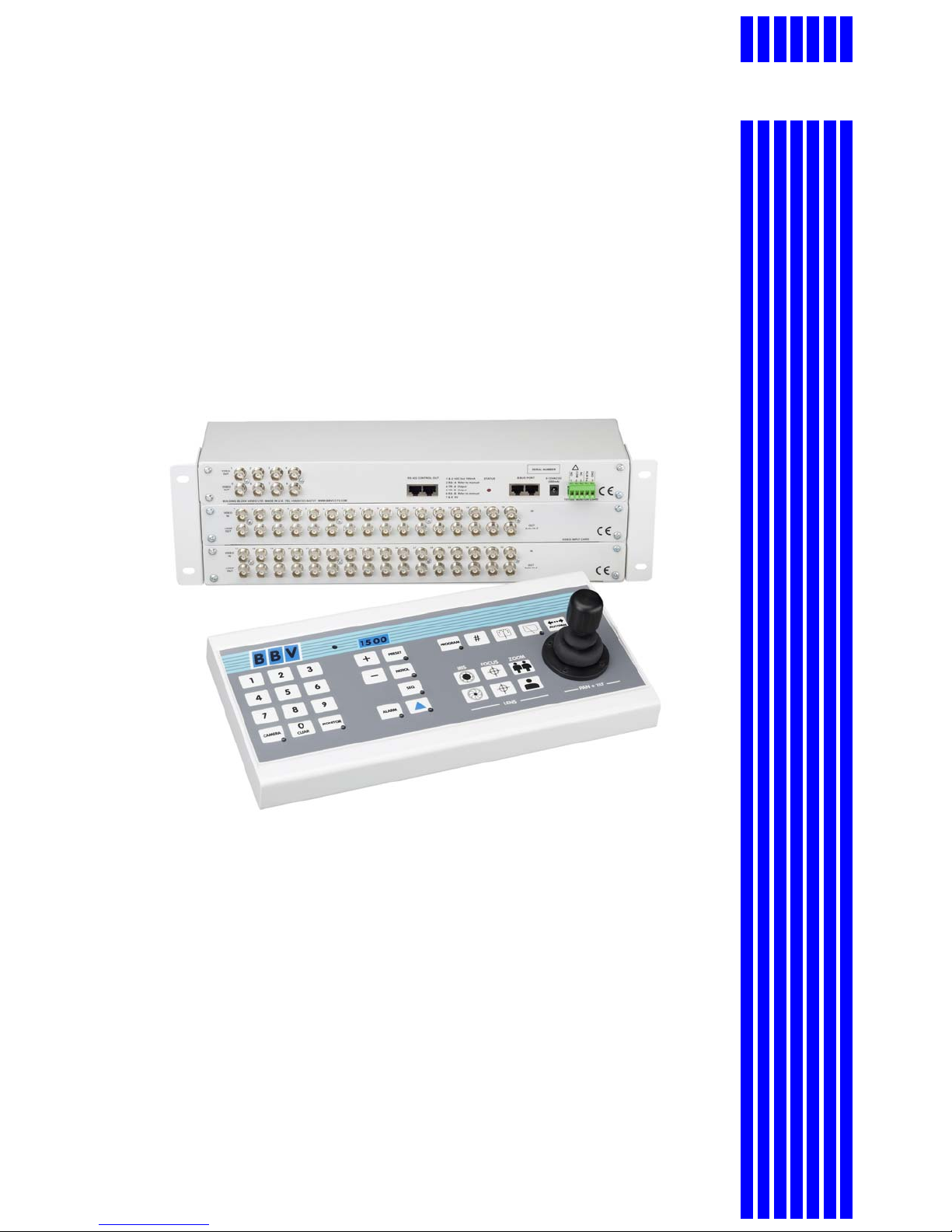
TX1500 system
BBV
TX1500 Matrix Video switching matrix
TX1500/KBD 3-axis joystick keyboard
TX1500/AL16 16 input alarm card
TX1500/BBUS-IF RS232/422/485 interface
Building Block Video Ltd.,
17 Apex Park
Diplocks Industrial Estate,
Hailsham, East Sussex, BN27 3JU UK.
Tel: +44 (0)1323 842727
Fax: +44 (0)1323 842728
Support: +44(0)1323 444600
Web Site: http://www.bbvcctv.com
Page 2

Contents
Unpacking 3
Safety Precautions 3
System Components 3
Description 4
TX1500 components 4
Product Codes 4
TX1500 System Example 5
BBUS control bus 6
BBUS example wiring 7
RS485 Telemetry port 8
RS485 wiring diagrams 8, 9
Video Input Card 10
Monitor Output Card 11
Matrix ALARM 00 & relay connector 11
96 Camera subrack wiring 12
Matrix Dianostics 13
TX1500/AL16 16 Input Alarm Ca rd 14
Configuring the TX1500 15
System Basics 16
Access Tables 17
Alarm Menus 18
Sequences 19
Camera Types 20
Vista Extended Commands 21
Telemetrey Functions 22
Set Password 23
System Parameters 24
System Parameters 2 25
Up-the-coax receiver programming 26
TX1500 USER GUIDE 27
Selecting a Camera 27
Selecting a Monitor 27
Moving a Camera 28
Lens Keys 28
Auxiliary Outputs 28
Go to Preset Position 29
Programming a Preset Position 29
Starting a Preset Patrol 30
Starting a Monitor Sequence 30
Triangle/Relay Key 30
Alarm Key 30
TX1500/KBD System Keyboard 31
TX1500/BBUS-IF Interface e xamples 32-34
TX1500 control protocol 35-37
TX1500 Manual V3.5 Dec 07 Page 2 of 40 TX1500 MATRIX
Page 3
UNPACKING
Inspect the packaging for signs of damage. If damage has occurred, advise the carriers and/or the suppliers
immediately. Unpack the units caref u lly and check that all the items are present an d correct.
SAFETY PRECAUTIONS
All normal safety precautions as laid down by British Standards and the Health and Safety at Work Act (or the
relevant National safety legislation if installing in a country outside the U.K.) should be observed, and
servicing should be referred to qualified se rv ice personnel.
SYSTEM COMPONENTS
Each complete system will comprise of at least the following:
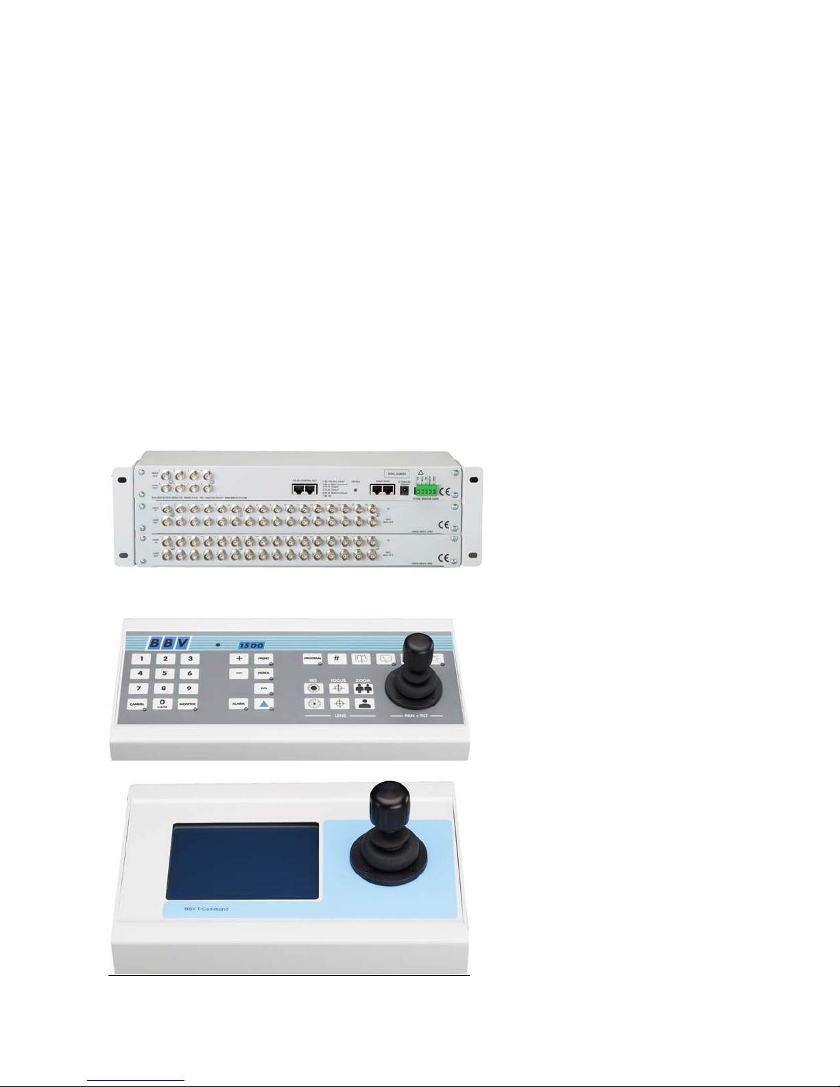
1 x TX1500 video matrix enclosed in a 19” sub rack.
1 x TX1500/KBD system keyboard or TCommand Touch Screen keyboard
2 x RJ45 straight patch cables
2 x RJ45 breakout boxes with self adhesive mounting pad
2 x 9Vdc 500mA power supply (1 for the matrix and 1 for the keyboard)
TX1500/32/8 matrix
Standard TX1500/KBD System Keyboard
Optional T Command Touch Screen Keyboard
TX1500 Manual V3.5 Dec 07 Page 3 of 40 TX1500 MATRIX
Page 4

OVERVIEW
The TX1500 is a video matrix and telemetry control system offering control of up to 96 cameras from 4 control
positions. Eight monitor outputs are provid ed with monitors 1,2,3 & 4 having on screen display.
BBV & VISTA up-the-coax and BBV 485 & VISTA 485 linked receivers and domes can be controlled
when viewed on any monitor. Pelco and VCL up-the-coax control is limited to monitors 1-4.
Site alarms and contacts are handled with alarm cards, each providing 16 inputs. Up to 6 alarm cards can be
linked into the TX1500 system either locally or remotely offering 96 alarm inputs
The TX1500/BBUS-IF interface, which appears as another keyboard, gives off-site control, via video/data
transmission equipment, and local control from PC and other equipment. The interface can be controlled
using either the TX1000 or TX1500 cont rol protocol via either RS232 or RS42 2/485.
The TX1500 matrix communicates with all keyboards, alarm cards and BBUS-IF interfaces via a polled 4-wire
multidrop RS422 control bus named BBUS.
The matrix itself is in a subrack which can be fitted to a 19” rack using supplied ‘ears’ that can be mounted on
the front or rear face of the subrack. By fitting the ears on the back of the subrack, it can also be wall
mounted.
Alarm cards, BBUS-IF and StarCards are supplied in 1U sub racks as standard or can be fitted into the
subrack with the matrix if specified when ordering.
Larger subracks than standard can be supplied if specified when ordering.
PRODUCT CODES
TX1500/16/8 16 camera, 8 monitor matrix inc keyboard (supplied in 3U su bra ck)
TX1500/32/8 32 camera, 8 monitor matrix inc keyboard (supplied in 3U su bra ck)
TX1500/48/8 48 camera, 8 monitor matrix inc keyboard (supplied in 5U su bra ck)
TX1500/64/8 64 camera, 8 monitor matrix inc keyboard (supplied in 5U su bra ck)
TX1500/80/8 80 camera, 8 monitor matrix inc keyboard (supplied in 7U su bra ck)
TX1500/96/8 96 camera, 8 monitor matrix inc keyboard (supplied in 7U su bra ck)
TX1500/KBD keyboard with 3-axis joystick
TX1500/AL16 16 input alarm card, volts free normally closed inputs
TX1500/BBUS-IF BBUS Interface to allow control from a PC or ot her 3
STARCARD StarCard with 8 x RS422/485 outputs to allow star wired te lemetry
STARCARD/CONVERTER As STARCARD with built in protocol conversion to allow control of domes
etc.
rd
party equipment
EXPANDING AN EXISTING SYSTEM on site (maximum of 96 camera inputs)
Camera Inputs Number of video input cards Minimum subrack Size
32 2 3U
48 3 5U
64 4 5U
80 5 7U
96 6 7U
Larger subracks can be ordered with the product code shown below. All the cards from the existing subrack
must be transferred to the new subrack. Note all the external connections to aid re-commissioning the system.
PRODUCT CODES
TX1500/EXP16(17-32) 16 video input card to expand from a 16 camera to 32 camera system
TX1500/EXP16(33-48) 16 video input card to expand from a 32 camera to 48 cam er a system
TX1500/EXP16(49-64) 16 video input card to expand from a 48 camera to 64 camera system
TX1500/EXP16(65-80) 16 video input card to expand from a 64 camera to 80 camera system
TX1500/EXP16(81-96) 16 video input card to expand from a 80 camera to 96 cam er a system
3U TX1500/3U-SUBRACK
5U TX1500/5U-SUBRACK
7U TX1500/7U-SUBRACK
TX1500 Manual V3.5 Dec 07 Page 4 of 40 TX1500 MATRIX
Page 5
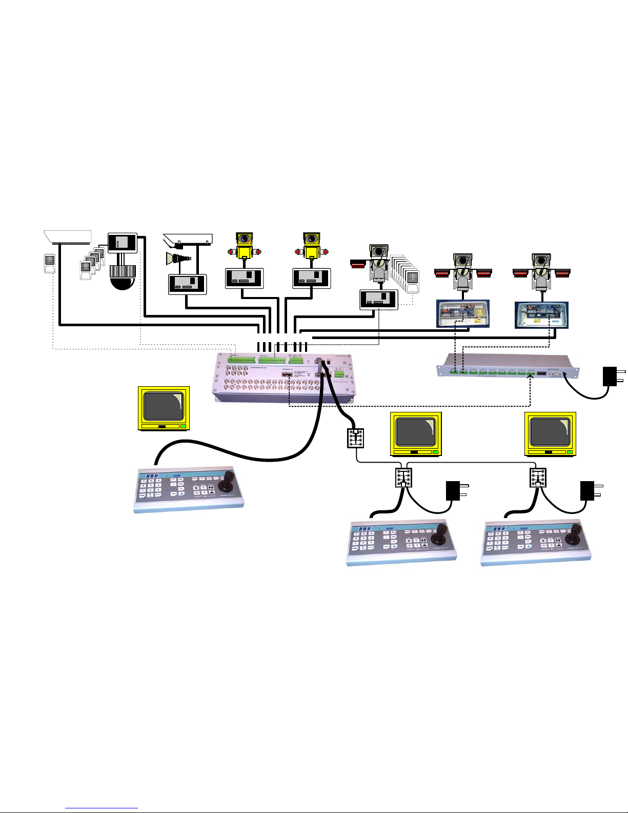
TX1500 Manual V3.5 Dec 07 Page 5 of 40 TX1500 MATRIX EXAMPLE
Rx100
+ dome camera
STATIC
Rx200
+ panning camera
Rx300
+ pan/tilt camera
Rx400P
+ preset pan/tilt camera
TX1500/16/8/16AL Matrix
TX1500/KBD
Rx400DC
+ DC preset pan/tilt
camera
video in - coax
RS485 StarCard 8 outputs
TX1500/KBD TX1500/KBD
RJ45 Breakout
Box
twin STP
Rx45X
Multi-protocol
+ AC Preset pan/tilt
camera
Rx55X
Multi-protocol
+ DC preset pan/tilt
camera
Page 6
BBUS CONTROL BUS
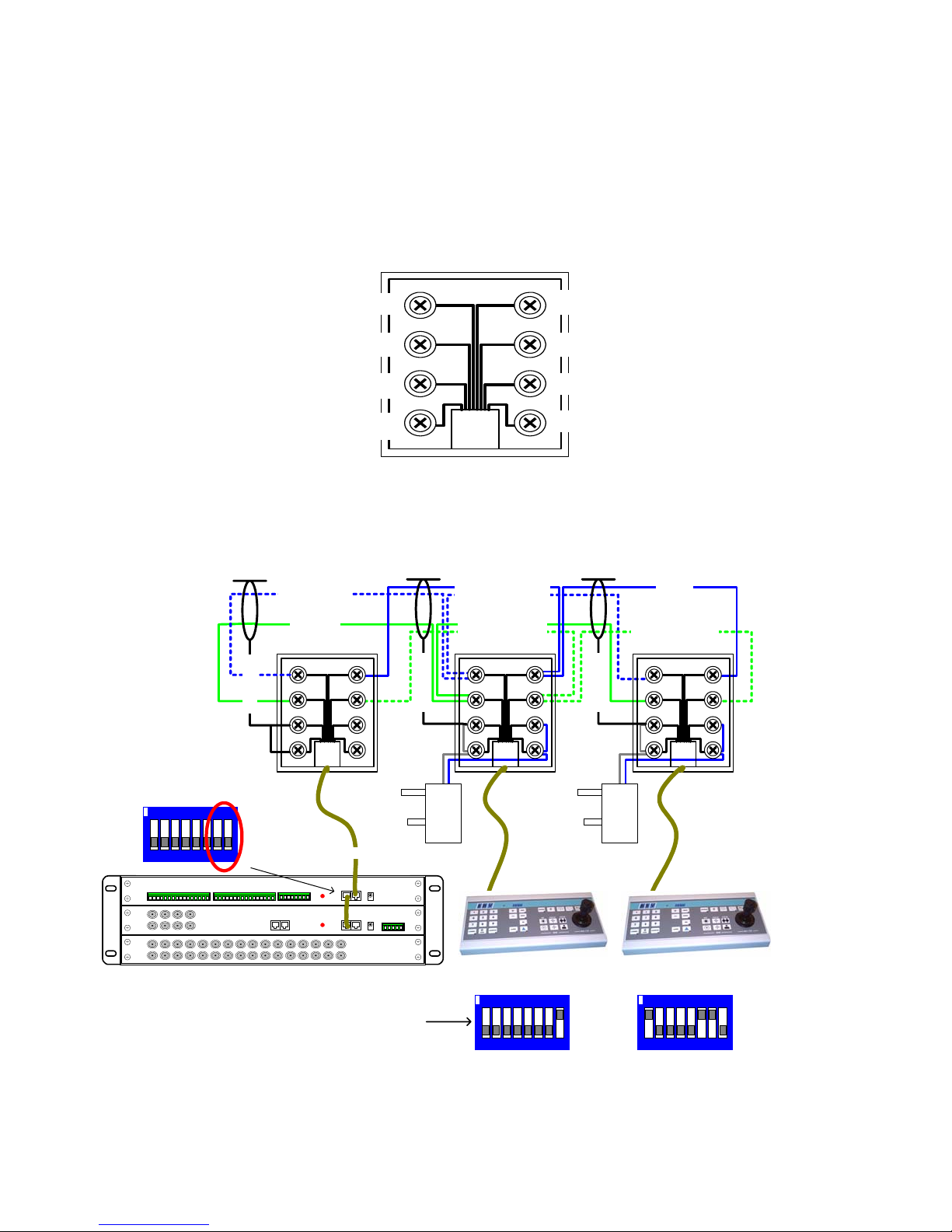
The TX1500 communicates with all keyboards, alarm cards and BBUS-IF interfaces via a polled 4 wire multidrop
RS422 control bus named BBUS.
All the units are equipp ed with st andard RJ45 c onnec tors al lowing cat 5 pa tch cab les to b e used to conn ect over
short distances. On the larger sites RJ45 break out boxes are used to link between cat 5 cables and good
quality screen twin twisted pair data cable. Suitable types are the following Belden cables: 9842, 9829, 8162,
8132.
TxB from MONITOR CARD = 5
(BLUE/WHITE)
RxB to MONITOR CARD = 6
(GREEN)
(0V) SCREEN = 7
(0V) SCREEN = 8
4 = TxA from MONITOR CARD
(BLUE)
3 = RxA to MONITOR CARD
(GREEN/WHITE)
2 = DO NOT USE (+V)
1 = DO NOT USE (+V)
Fig 5. BBUS - RJ45 breakout box connector, MONITOR CARD end of BBus.
BBUS maximum distance 1200M end-to-end
BLUE/WHITE
GREEN
SCREEN
Alarm card
BBUS Un-Terminated
Switch 7-8 OFF
Card 1 alarm 1-16
ON
Tx Data (FROM CPU)
Rx Data (TO CPU)
SCREEN
0V +9Vdc 0V +9Vdc
BLUE
GREEN/WHITE
SCREEN
12 3456 78
RJ45 patch cable max length = 2M
1-5 = Keyboard Address
6&7 = BBUS termination
8 = Program Key Enable
Fig 6. Keyboard BBUS wiring
TX1500 Manual V3.5 Dec 07 V2 Page 6 of 40 TX1500 MATRIX
Keyboard 1
BBUS Un-Terminated
ON
123456 78
Keyboard 2
BBUS Terminated
ON
12 3456 78
Page 7
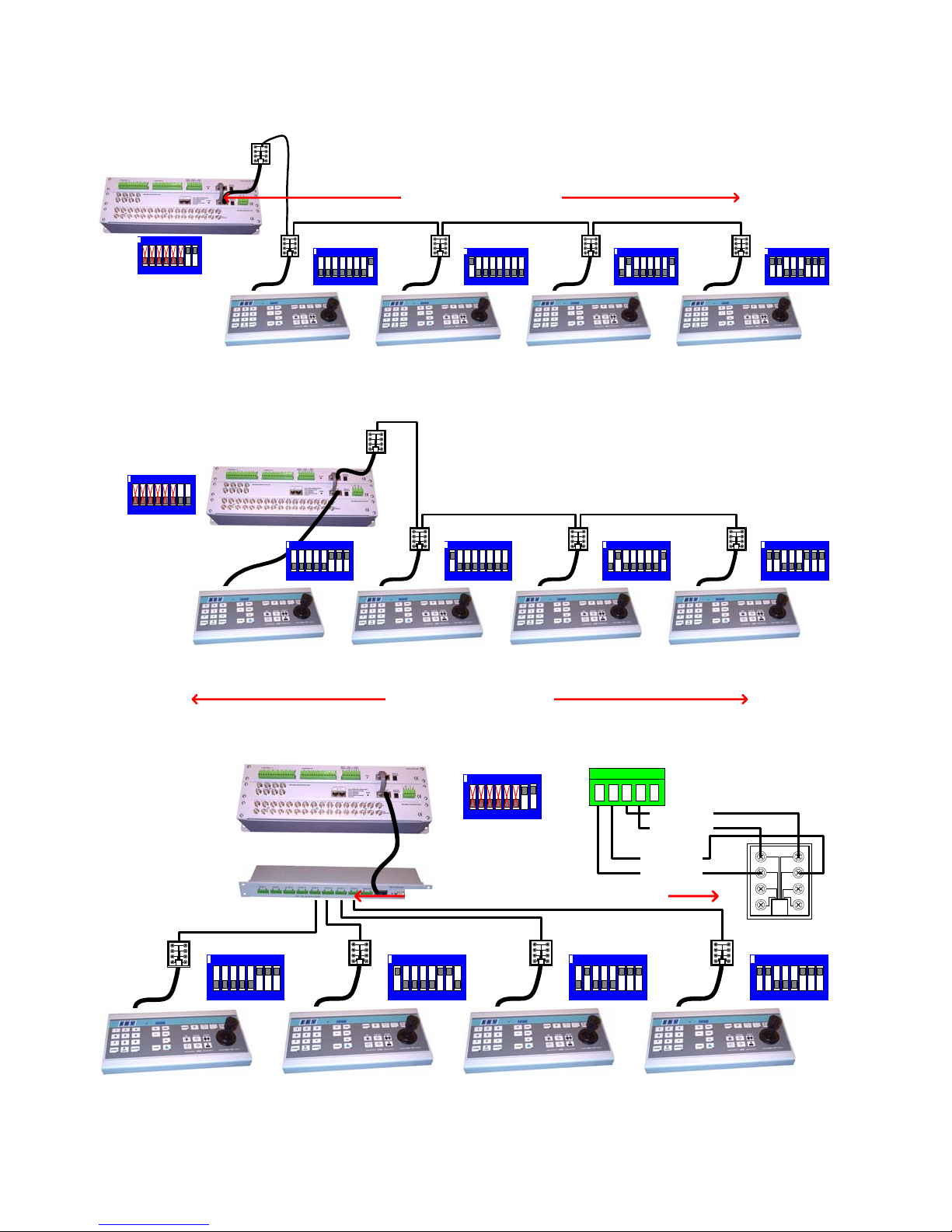
SYSTEM BBUS WIRING EXAMPLES
The following diagrams show examples of v ar i ou s wiring schemes.
BBUS maximum distance 1200M
ON
12345678
Matrix SW2
BBUS Termination ON
Keyboard 1
BBUS Termination OFF
PROGRAM Enabled
ON
12345678
ON
123456 78
Keyboard 2
BBUS Termination OFF
PROGRAM Disabled
ON
123456 78
Keyboard 3
BBUS Termination OFF
PROGRAM Enabled
Keyboard 4
BBUS Termination ON
PROGRAM Enabled
Fig 7. Example with all keyboards daisy chained from the TX1500 matrix using a single BBUS leg.
ON
123456 78
Matrix SW2
BBUS Termination OFF
Keyboard 1
BBUS Termination ON
PROGRAM Enabled
ON
123456 78
Keyboard 2
BBUS Termination OFF
PROGRAM Disabled
ON
12345678
ON
123456 78
Keyboard 3
BBUS Termination OFF
PROGRAM Enabled
Keyboard 4
BBUS Termination ON
PROGRAM Enabled
BBUS maximum distance 1200M
Fig 8. Example with all keyboards daisy chained from the TX1500 matrix using two BBUS legs.
ON
12345678
ON
123456 78
ON
123456 78
Keyboard 1
BBUS Termination ON
PROGRAM Enabled
Keyboard 2
BBUS Termination ON
PROGRAM Disabled
Fig 9. Use of a STARCARD to allow star wiring of key bo ar ds.
TX1500 Manual V3.5 Dec 07 Page 7 of 40 TX1500 MATRIX
ON
123456 78
STARCARD
5 4 3 2 1
Matrix SW2
BBUS Termination ON
STARCARD to KEYBOARD maximum distance 1200M
ON
123456 78
ON
123456 78
Keyboard 3
BBUS Termination O N
PROGRAM Enabled
3/TRA -> 4
2/TRB -> 5
4/RA -> 6
5/RB -> 3
KEYBOARD
ON
123456 78
Keyboard 4
BBUS Termination ON
PROGRAM Enabled
Page 8
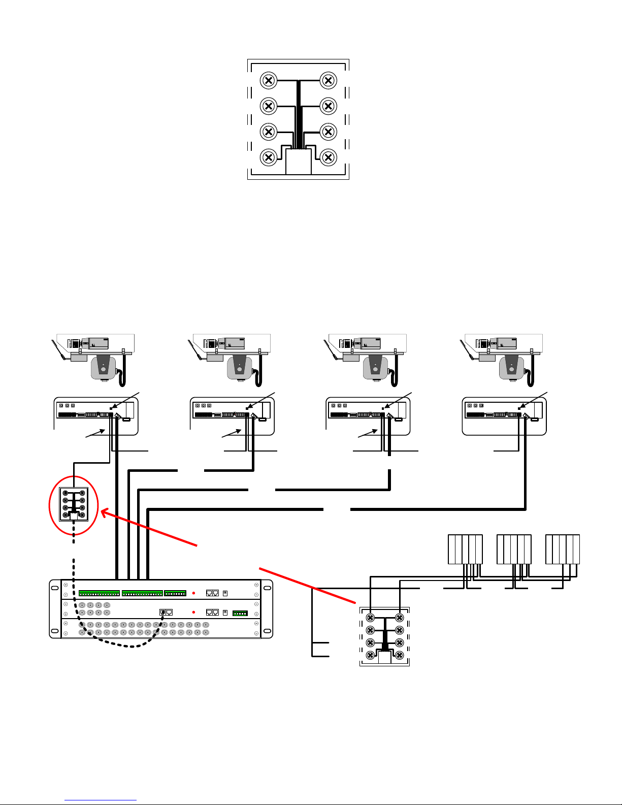
RS485 TELEMETRY OUT
TxB to Telemetry Receiver RB(-) = 5
4 = TxA to Telemetry Receiver RA(+)
(BLUE)(BLUE/WHITE)
DO NOT USE = 6
GROUND/SCREEN = 7
GROUND/SCREEN = 8
3 = DO NOT USE
2 = DO NOT USE
1 = DO NOT USE
Fig 10. TELEMETRY – RJ45 breakout box connector.
This port provides telemetry control via BBV RS485. Again a Cat 5 RJ45 patch cable and breakout box is used to
connect the telemetry receive rs via single twisted pair cable. It is possible to either wire the network in a daisy
chained or star configuration using an optional RS485 star card.
RS485 wiring configurations are shown below and on the following page.
RS485 TELEMETRY WIRING CONFIGURATIONS
Camera 1 Camera 2 Camera 3 Camera 4
Rx45X/55X Address 1 Rx45X/55X Address 2 Rx45X/55X Address 3Un-Terminated Un-Terminated Un-Terminated
Keep stub length as
short as possible
Keep stub length as
short as possible
RS485 Telemetry
Coax
Keep stub length as
short as possible
RS485 Telemetry RS485 Telemetry
Maximum length of RS485 from Tx1500 to last receiver - 1200M
Coax
Coax
D
RJ45 patch cable
E
T
A
I
L
E
D
V
I
E
W
TxB to RB (-) = 5
DO NOT USE = 6
RJ45 breakout box
SCREEN = 7
SCREEN = 8
Fig 11. Daisy Chained RS485 Telemetry Wiring
screen
4 = TxA to RA (+)
3 = DO NOT USE
2 = DO NOT USE
1 = DO NOT USE
Rx45X/55X Address 4
Rx457/557 RS485 connectors
T
B
screen
T
G
RAR
R
R
N
B
D
A
B
screen
T
T
G
RAR
R
R
N
D
A
B
Terminated
T
T
G
R
R
N
D
A
B
RAR
B
TX1500 Manual V3.5 Dec 07 Page 8 of 40 TX1500 MATRIX
Page 9
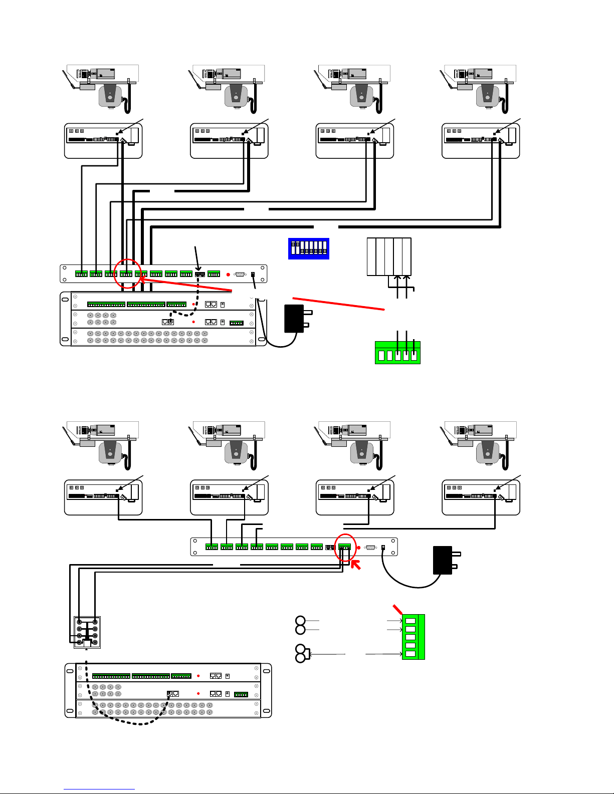
Camera 1 Camera 2 Camera 3 Camera 4
Rx45X/55X Address 1 Rx45X/55X Address 2 Rx45X/55X Address 3Terminated Terminated Terminated
RS485 TELEMETRY
1200M Max
RS485 TELEMETRY 1200M M ax
Coax
RS485 TELEMETRY 1200M Max
Coax
RS485 TELEMETRY 1200M Max
Coax
RJ45 Patch Cable
BBV Star Card
12 345678
StarCard SW3 must be set
to 4 wire as shown.
D
E
T
A
I
L
E
D
V
I
E
W
T
T
G
R
R
N
D
A
B
RAR
TRA to RA
B
TRB to RB
Rx45X/55X
Telem Conn
S
C
R
E
E
N
StarCard
Star output
Fig 12. Star Wired Configuration using the optional BBV StarCard
Camera 1 Camera 2 Camera 3 Camera 4
Rx45X/55X Address 4
Terminated
Rx45X/55X Address 1 Rx45X/55X Address 2 Rx45X/55X Address 3Terminated Terminated Terminated
RS485 to each receiver
Maximum 1200M
RJ45 patch cable
screen
RS485 Maximum 1200M
RJ45
Breakout Box
5
4
7
8
From TX1500 TB(Pin 5)
From TX1500 TA(Pin 4)
D
E
T
A
I
L
E
D
V
I
E
W
n
r
e
e
c
S
Rx45X/55X Address 4
RB
RA
TRA
TRB
GND
MASTER
Fig 13. Use of StarCard mounted remotely, reducing cable runs
TX1500 Manual V3.5 Dec 07 Page 9 of 40 TX1500 MATRIX
Terminated
Page 10
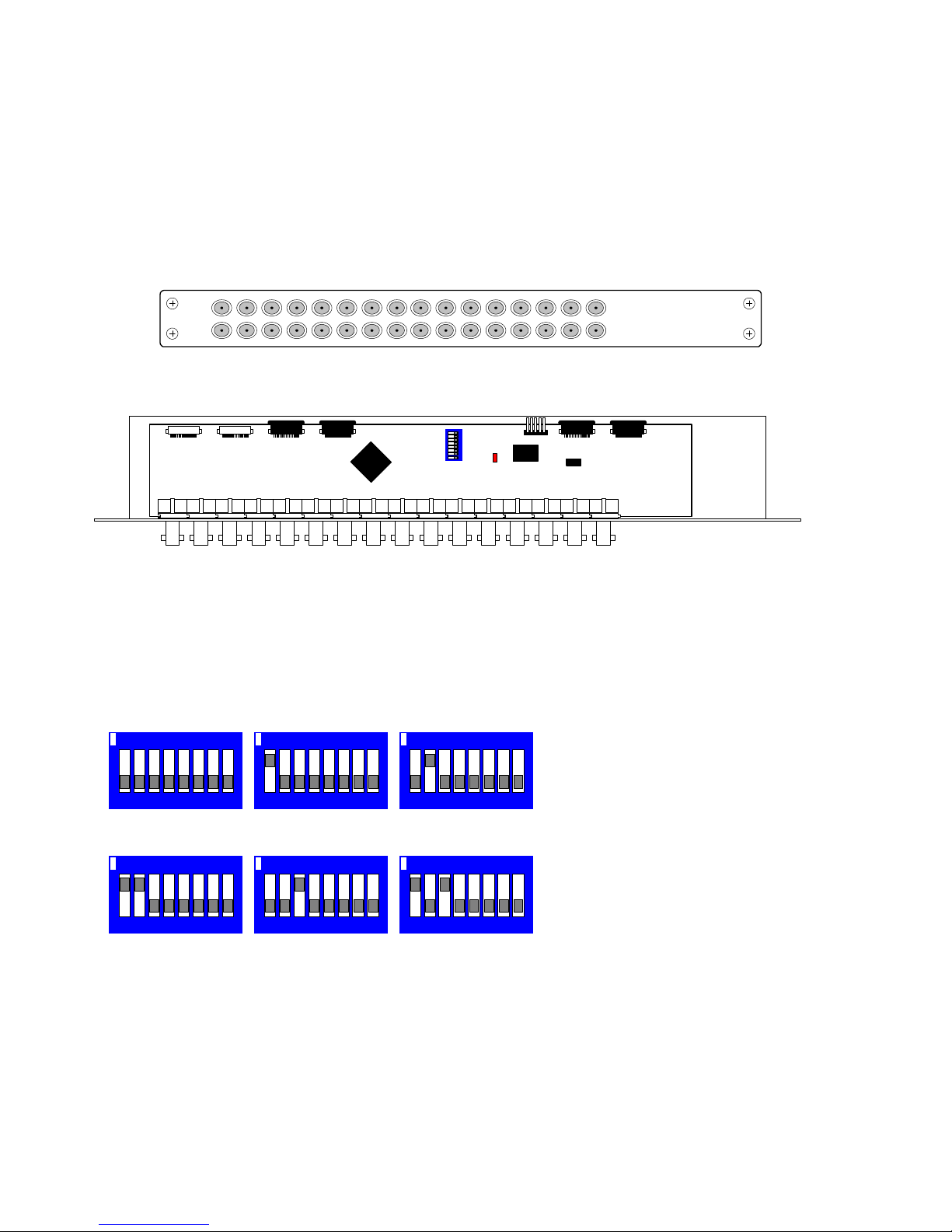
VIDEO INPUT CARD
The Video Input Card is used to connect 16 camera inputs to the TX1500. Systems larger
than 16 cameras will use multiple cards. A board mounted DIL switch is used to set the card’s
camera number range.
Each input has a corresponding looping output on the lower BNC connector. The camera
inputs are passively terminat ed at 75Ω and auto de-terminate when a BNC plug is connected
to the looping output. Up to 6 cards can be connected in a matrix to control up to 96 cameras.
Video Input card Front Panel View
1234567891011
Video bus Control bus
1213141
16
5
VIDEO INPUT S
BBV
SW1
J17
LD1
PL1 PL5PL2PL6PL3PL4
00101
Top view of Tx1500 video input board PCB00101
The switches for each card will be set at the factory however if the system is to be upgraded
then please set the new card(s) swit che s as shown below.
SW1 Camera Range
Camera 1 - 16 Camera 17 - 32 Camera 33 - 48
ON
12345678
123456 78ON12 3456 78
ON
Camera 49 - 64 Camera 65 - 80 Camera 81 - 96
ON
12345678ON123456 78ON12 3456 78
Video Input card SW1 address switch setting
TX1500 Manual V3.5 Dec 07 Page 10 of 40 TX1500 MATRIX
Page 11
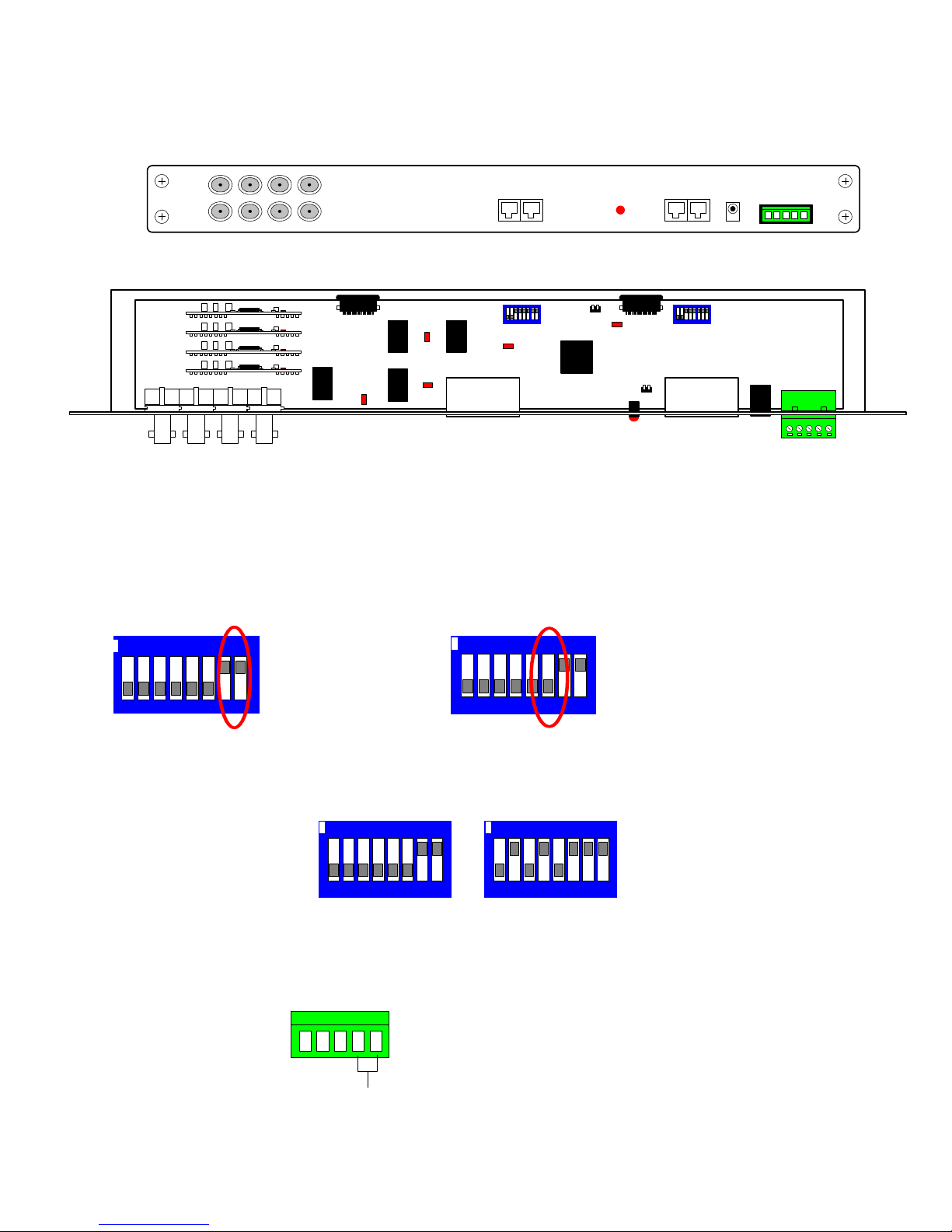
MONITOR OUTPUT CARD
This card provides the 8 monitor outputs, BBU S , RS4 85 telemetry and a relay output.
Internal switches are used during specific BBV tests that should not require on site adjustment.
Monitor Output card Front Panel View
12 34
56 78
MONITORS
B-BUSTELEMETRY
12Vdc
ALARM
LD6
LD5
LD4
RS485
OUT
SW2
LD3
PROG
LINK
LD2
LD1
PL2PL1
SW1
L9
B-BUS
01002
Monitor Output card internal view
LD1 STATUS – Front Panel indication of syst e m an d BBUS operation. Refer to page 16.
Internal LEDs,
LD2 – BBV debug use.
LD3, 4, 5, 6 – ON whilst coaxial telemetry is transmitted to the camera
For normal operation the internal switches must be as shown below:
SW1 SW2
ON
12 3456 78
B-BUS RS485
ON = Terminated
OFF = Un-terminated
ON
12 3456 78
RS485 Te lemetry
ON = Terminated
OFF = U n-terminated
To reset system to factory defaults:- Power off the TX1500, set the switches as below and p ower up
the TX1500. On screen instructions are displayed on monitor 1 output.
SW1 SW2
Power Up Factory Reset
ON
123456 78
NOTE: The Power Up Factory Reset option will delete all TX1500 parameter programming.
Contact BBV technical support for guidance. +44(0)1323 444600.
ON
123456 78
CHANGEOVER RELAY
operated by the triangle
key
Volts fre e c ontacts fo r lo w
voltage switching only
1 2 3 4 5
NO
TX1500 Manual V3.5 Dec 07 Page 11 of 40 TX1500 MATRIX
COM
Alarm 00 input can
trigger one of several
actions, refer to page 19
Input from volts fre e,
normally closed contacts
NC
ALARM 00
Page 12
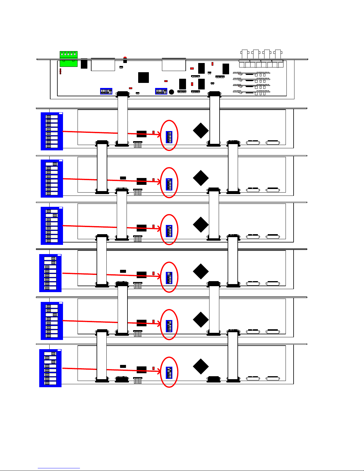
96 CAMERA SYSTEM SUBRACK CARD CONFIGURATION
B-BUS
SW1
01002
LD1
L9
LD2
PL2PL1
LINK
PROG
R
123456 7
ON
8
123456 7
ON
00101
00101
R
I
B
B
O
00101
00101
N
R
I
B
8
123456 7
ON
8
1234567
ON
B
O
00101
00101
N
R
I
B
8
123456 7
ON
8
123456 7
ON
B
O
8
Wiring and switch settings for Video Input cards and Monitor Output card.
N
I
B
B
O
PL1 PL5PL2PL6PL3PL4
N
Camera 1 - 16
LD1
J17
Camera 17 - 32
LD1
PL1 PL5PL2PL6PL3PL4
J17
R
I
B
B
O
PL1 PL5PL2PL6PL3PL4
N
Camera 33 - 48
LD1
J17
Camera 49 - 64
LD1
PL1 PL5PL2PL6PL3PL4
J17
R
I
B
B
O
PL1 PL5PL2PL6PL3PL4
N
Camera 65 - 80
LD1
J17
Camera 81 - 96
LD1
PL1 PL5PL2PL6PL3PL4
J17
OUT
LD4
RS485
LD3
SW2
J9
LD5
J11
J10 J8
R
I
B
SW1
B
O
N
SW1
R
I
B
SW1
B
O
N
SW1
R
I
B
SW1
B
O
N
SW1
LD6
L11
L10
BBV
BBV
BBV
BBV
BBV
BBV
Monitor Output Card
R
Video Input Card
I
B
B
O
N
Video Input Card
R
I
Video Input Card
B
B
O
N
Video Input Card
R
I
Video Input Card
B
B
O
N
Video Input Card
TX1500 Manual V3.5 Dec 07 Page 12 of 40 TX1500 MATRIX
Page 13

MATRIX DIAGNOSTICS
The matrix STATUS led indicates system operation as follows:
Flashing Dimly The matrix is powered with at least one keyboard connected. Use 58# to display
the keyboard numbers that the matrix ha s detected on the BBUS.
Mainly OFF, 1 second ON The matrix is powered with no keyboards connected. – If keyboards are
connected then make s ur e tha t e ach k eybo ard a dd r ess is u niq ue be tw ee n 0 – 3.
Keyboards sharing an address will cause the matrix to ignore both keyboards
with unpredictable results.
OFF Either the matrix is not powered or has an internal fault. If the power supply
seems fine then please contact technical support for further assistance.
Several commands exist that allow on site diagnostics. These commands must be entered from keyboard 1 and
display results on monitor output 1.
51# Dis play the matrix firmware version, number of resets and watchdog resets.
TX1500 Version shows the matrix firmware version number ie 2.3
resets shows the number of times that the system has lost power or the menu has b ee n acce ssed .
watchdogs shows the number of times the matrix watchdog has reset the matrix. A high figure here can
indicate that there may be interference or power fluctuations.
55# Coaxial telemetry on.
With normal operation, the coaxial telemetry is only transmitted to a receiver whilst a camera is being
controlled. After a short period the teleme try tran smis s ion is st oppe d. This is pre vent interfere nce to syn c
separators in DVRs etc. When trouble shooting telemetry problems the telemetry should be on all the
time so the 55# command would be used and then the receiver CABLE and ER ROR leds inspected.
Pressing # again will stop the telemetry transmission.
56# Display the status of matrix s witch SW1, the display shows a HEX number which corresponds to the
switch settings for SW1. The number is displayed whilst the # key is pressed. Releasing the # key will
clear the number from the screen.
Number displayed SW1 switch
0 1 - 6 OFF
1 1 ON
2 2 ON
4 3 ON
8 4 ON
10 5 ON
20 6 ON
When more than 1 switch is ON then the number displayed will the sum of the values of all switches that
are ON, ie. 1,2 ON, display shows 03 , 1,2,3,4 ON displays 0F
RS485 telemetry directly from the TELEMETRY port and should not normally be s elected.
Example numbers that could be displa y ed
0 = normal mode
1 = DIXONS mode – This is a special mode developed for DS G driv in g Ma rk Me rcer
57# Display the status of matrix switch SW2 as per 56#.
2A = SW2-2/4/6 ON = FACTORY INITIALISATION on a power up. This is used to clear any
programming and load default values. Useful if the matrix has had a corrupted programming. Once
powered up turn all SW2 switches OFF again to prev e nt further accidental initialisations.
58# Display number of keyboards or BBUS/I-F with addresses connected to the matrix along with the
software version of each keyboard or BB US/I-F.
TX1500 Manual V3.5 Dec 07 Page 13 of 40 TX1500 MATRIX
Page 14
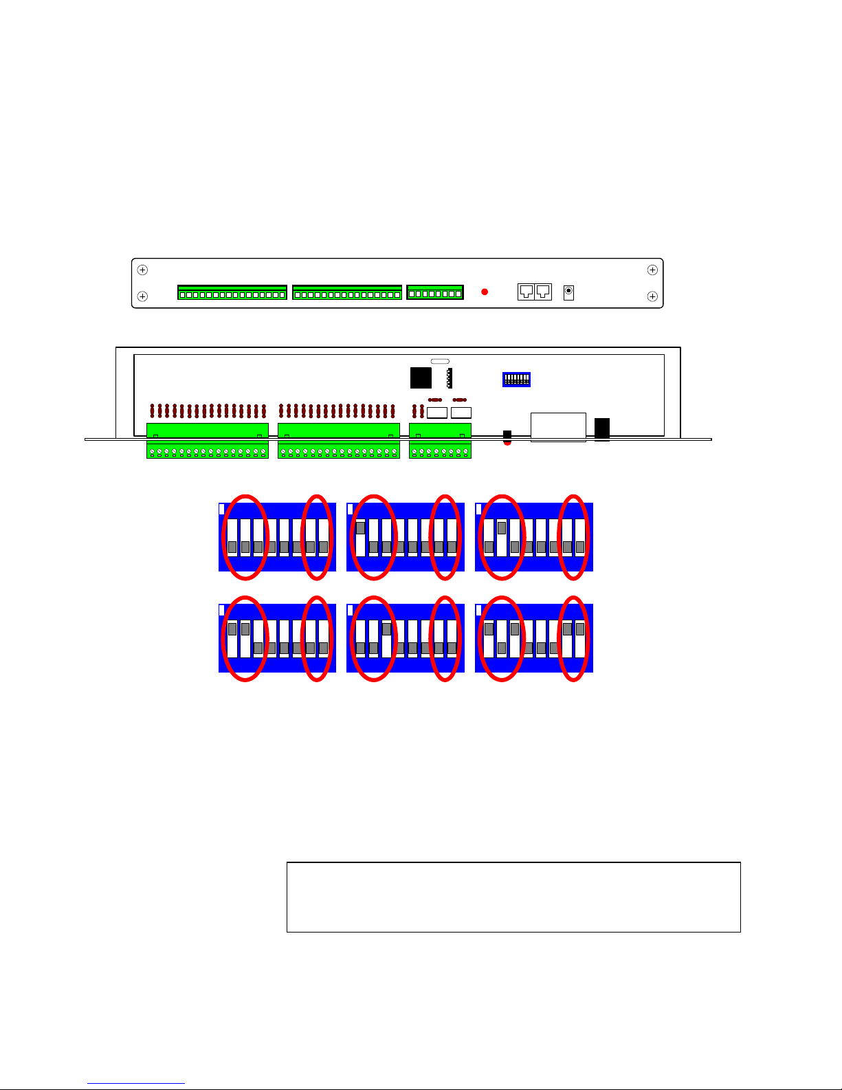
TX1500/AL16 - 16 ALARM INPUT CARD
–
Each alarm card provides 16 individu al normally closed volts free alarm inputs. The card communic ates via the BBUS
with the monitor output card. Power is supplied either via the BBUS interface when the alarm card is mounted in the
TX1500 subrack or via an external 9Vdc supply when mounted remotely.
NOTE: Only 1 alarm card can be powered from the BBUS port.
The power led is used as a status indication and shows the following:
Mainly ON, flashing OFF when the alarm card is polle d, approx 2-3 times every second. (NORMAL )
OFF permanently – alarm card not powered or faulty.
ON permanently – Not polled by MONITOR card, BBUS cable faulty or ALARM card faulty.
ALARM INPUT 1-8 ALARM INPUT 9-16
Fig 23. Alarm card front panel view
OUTPUTS
J1
RY2 RY1
LD1
B-BUS
SW1
12Vdc
B-BUS
02002
Fig 24.
Alarm
card
internal
view
SW1 is used to set the alarm card address as follows:
Card 1 alarm 1-16 Card 2 alarm 17-32 Card 3 alarm 33-48
ON
123456 78
123456 78ON123456 78
Card 4 alarm 49-64 Card 5 alarm 65-80 Card 6 alarm 81-96
123456 78ON123456 78ON123456 78
ON
ON
Switches 7 & 8
BBUS RS485 Termination
ON = Terminated
OFF = Un-terminated
Must be ON if the alarm card is at
the end of line and OFF otherwise.
Alarm card 6 shown as end of line.
Fig 25. Alarm card SW1 address switch settings
Each alarm card has two single pole changeover relays called Relay 1 and Relay 2. These relays can be driven
manually and also from alarm activations. The system relay numbers are assigned as follows:
Alarm Card Relay 1 Relay 2
1 1 2
2 3 4
3 5 6
4 7 8
5 9 10
6 11 12
Note: alarm card relay 1 cannot be controlled from the keyboards as it is an
alarm output contact that changes state when any alarm becomes active.
This allows it to be used to switch a VCR into realtime recording etc. The
duration is set in the matrix menu.
Relay 1 Time
TX1500 Manual V3.5 Dec 07 Page 14 of 40 TX1500/AL16 16 INPUT ALARM CARD
Page 15
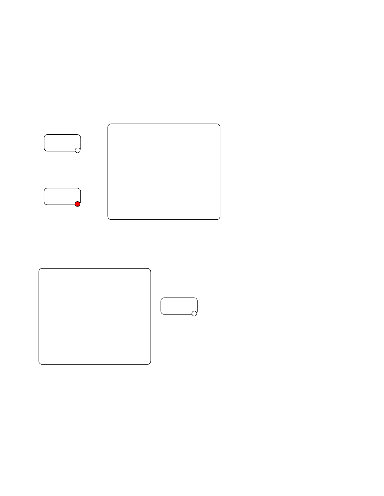
CONFIGURATION USING THE TX1500 MENUS
NOTE only keyboard 1 can access the TX1500 system menu and only monitor 1 can display the menu.
Out of the box the TX1500 is configured to control BBV coaxial telemetry on all cameras and all keyboards can control
all the monitors and cameras.
The TX1500 menu system allows the unit to be configured to your customer’s site requirements.
To access the menu select monitor 1 by pressing ‘1’ ‘MON’ and use keyboard 1. Press and hold the ‘PROGRAM’ key
for 2-3 seconds and the following screen will be disp layed and the ‘PROGRAM’ led is lit. If the menu is not displayed
then check that the program key is enab led on the keyboard by turning switch 8 ON.
Press for 2 seconds
PROGRAM
The menu is displayed Enter the six digit PIN using
and the PROGRAM led keys 0 – 9.
is lit.
PROGRAM
Use the joystick left and right if a digit is entered incorrectly.
The TX1500 Main Menu is displayed if the PIN is correct otherwise the TX1500 reverts to normal control.
TX1500 - Main Menu
System Basics
Access Tables
Alarm Menus
Sequences
Camera Types
Set Passwords
System Parameters
Exit press + to select
Each menu item is described on the following pages
Enter Pin Number
* * * * * *
+ or - = Enter Key
Joystick to Navigate
Press Program to exit
Exit
To navigate through the menu, us e the joystick and either the +/- keys to
toggle a value or the numeric keys 0-9 if a value is required.
To exit the menu press the PROGRAM key at any point.
PROGRAM
The default PIN is 999999
TX1500 Manual V3.5 Dec 07 Page 15 of 40 MATRIX PROGRAMMING/USER GUIDE
Page 16

SYSTEM BASICS
This example screen shows the settings for a site with 10
cameras, 2 keyboards and a single alarm card with 16 alarm
System Basics
Maximum Camera number 10
Maximum Alarm number 16
Text on Monitors 1+2+3+4
Display Line 9
System Type PAL
Number of Keyboards 2
Return
Maximum Alarm number:
Specifies how many alarm inputs are connected to the matrix. Set as below:-
Alarm cards
0 0
1 16
2 32
3 48
4 64
5 80
6 96
Text on Monitors:
Monitor outputs 1 – 4 display the camera number, monitor number and other messages. Text on these monitors can be
disabled by using the + or – key to cycle thr ou gh options.
Display Line:
The TX1500 status line can be moved up or down on the screen to prevent the TX1500 text from being overwritten by
the text from other components of the system. Use +/- to cycle through values.
0 being the top of the screen and 10 t he bottom of the screen.
System Type:
Sets the CCTV video standard as PAL or NTSC. Use the +/- keys to select the stan da rd. Normally PAL in the UK.
Number of Keyboards:
Sets the number of keyboards connected to the matrix
Return:
Returns to the TX1500 Main Menu.
Maximum Alarm
number
inputs.
Maximum Camera number:
Specifies how many video inputs are connected to the matrix and
prevents switching to non-existent cameras. Valid values are 01 96
TX1500 Manual V3.5 Dec 07 Page 16 of 40 MATRIX PROGRAMMING/USER GUIDE
Page 17

ACCESS TABLES
One of the advanced features of the TX1500 system is the ability to prevent specific cameras from being displayed on
specific monitors and to prevent specific keyboards from moving cameras.
The Access Table screen is used to program which monitors each k eyboard can control. A setting of ‘Y’ is used if the
keyboard is allowed to control a monito r an d ‘N’ to prevent control.
This screen shows the settings for a site with two keyboards. Each
Access Table
Keyboard to Monitors
1 2 3 4 5 6 7 8
1 Tx 1500 v6 Y N N N N N N N
2 Tx 1500 v6 N Y N N N N N N
3 Not Fitted N N N N N N N N
4 Not Fitted N N N N N N N N
Return
On power up the matrix interrogate s dev ices on the BBUS and all control devices are displayed on this screen.
Recognised control devices are:-.
Displayed Description
TX 1500 Standard TX1500 joystick keyboard
TCommand Touch Screen keyboard
232 I/F BBUS Interface allowing control from PC and from remote sites etc.
Allocating cameras to monitors and keyboards is programmed from the Camera Types scree n.
keyboard has it’s own monitor and is locked out of controlling the other
keyboard’s monitor.
i.e.
Keyboard 1 can control monitor 1 ONLY
Keyboard 2 can control monitor 2 ONLY
Pressing the +/- keys will toggle the value of each monitor between Y
and N.
NB: Keyboard 1 can always control mo nitor 1 a s this is used to setup the
matrix.
TX1500 Manual V3.5 Dec 07 Page 17 of 40 MATRIX PROGRAMMING/USER GUIDE
Page 18

ALARM MENUS
Alarm handling of the TX1500 is programmed from the Alarm Menu screens.
Up to four actions can be carried out following each alarm activation. Eg four cameras could move to preset positions to
triangulate onto an event.
On selection of Alarm Menus the following screen is displayed
This example shows a system with a single 16 input alarm card.
You have 16 alarms
enabled and connected
Edit Alarm number 00
Input Action Disable Alm
Alarm Beep Time 6 Seconds
Alarm Stack Automatic
Relay 1 Time 60 Seconds
Return
Input Action:
Sets the action for the ALARM 00 input on the matrix monitor board. Use +/- to cycle through the options.
No Action – ALARM 00 is not used.
Disable Alm – is used to disable all alarms when ALARM 00 is shorted to GND.
Alarm 00 – ALARM 00 is used as an alarm input in ad dit i o n t o t he TX1 50 0/ A L 16 alarm card inputs.
NOTE: Always handled in ‘AUTOMATIC’ mode, regardless of ‘Alarm stack’ setting.
Alarm Beep Time:
Number of seconds that all the keyboards ‘b eep’ following an alarm input. Use +/- to cycle through the values.
0, 4, 6, 8, 10, 15, 20 Seconds
Alarm Stack:
The matrix alarm handling can be automa tic, ie the system will drive camer as to presets as alar ms occur or require an
operator input before the al arm is actioned. Use the +/- to toggle bet ween Automatic and Manual.
Automatic – Alarm activations are handled automat i cally
Manual – The ALARM key must be pressed to acknowledge a n alarm activation
Relay 1 Time:
The number of seconds that the Relay 1 output of alarm card 1 is active following any alarm.
Use +/- to cycle through the various t ime delays. 10, 30, 60, 90, 120, 150, 200 or 250 seconds.
Enter the 2 digit alarm number you wish to program using the 0-9 keys. Eg enter 01 for alarm 1. The following screen
will then be displayed. See the relay number mentioned on page 17.
Alarm 1
kbd cam mon pre time
Act 1 01 1 01 30s
No Act 1 01 1 00 30s
No Act 1 01 1 00 30s
No Act 1 01 1 00 30s
Return Exit next prev
TX1500 Manual V3.5 Dec 07 Page 18 of 40 MATRIX PROGRAMMING/USER GUIDE
The TX1500 will display the total number of alarms that can be
programmed based on the Maximum Alarm number set in the System
Basics menu.
Each of the four actions can allow a camera to be moved to a preset
position and displayed on a mo nitor output. In additio n, if the monitor wa s
sequencing before the alarm occurred, after ‘time’ seconds the sequence
is re-started.
If alarms are taken into the local alarm input of a telemetry receiver that
supports local alarms, ie Rx100/Rx400DC/Rx45X/Rx55X, ‘pre’ must be
set to 00 as the preset will depend on the receiver alarm input. (See the
receiver manual for more details on loca l alarms.)
This simple example shows alarm 1 moving camera 1 to preset 1 and
display on monitor 1.
next and prev allow setting the alarm actions for the next and previous
alarm inputs.
Page 19

SEQUENCES
Each of the 8 monitor outp uts of the TX1500 can sequence between all or specific ca meras. Each camera can be
individually added or removed fr om each monitor se quence. For example, in a retail enviro nment public store monitors
are prevented from displaying sensitive areas of the store whilst monitors in the security office can sequence all
cameras.
Sequence Setup Selection
Cameras 01 - 08
Cameras 09 - 16
Cameras 17 - 24
Cameras 25 - 32
Cameras 33 - 40
Cameras 41 - 48
Cameras 49 - 56
Cameras 57 - 96
Return
Selecting Cameras 01 – 08 will display the following screen
monitor sequence setup
cam 1234 5678
1 2 Second YYYY YYYY
2 5 Second YYYY YYYY
3 15 Second YYYY YYYY
4 20 Second YYYY YYYY
5 25 Second YYYY YYYY
6 30 Second YYYY YYYY
7 Full Rand YYYY YYYY
8 Random YYYY YYYY
Return Menu Next8
Sequence types:
2/5/15… Second – standard sequence with a dwell time before displaying the next camera.
Random – The cameras are sequenced as above from lowest to highest but with a random dwell
time between each camera.
Full Rand – In Full Random the monitor will display a completely random camera for a random
period of time. This is useful for public display monitors on shop floor to prevent
shoplifters remembering the displayed sequence.
A camera will be in a specific monitor’s sequence if a Y is displayed or b e skipp ed if an N is displayed.
Use the + or – keys to toggle between Y and N.
Next8 displays the next bank of 8 cameras.
If a camera greater than the Maximum Camera Number is added to a
sequence this camera will be ignored when the sequence is running.
Monitors 1 to 8 are shown with mo nitor 1 the top line and monitor 8 the
bottom line.
The first item is the type of sequence or the dwell time if running a
standard sequence. The screen on the left shows all the variants of
sequences and dwell times.
TX1500 Manual V3.5 Dec 07 Page 19 of 40 MATRIX PROGRAMMING/USER GUIDE
Page 20

CAMERA TYPES
These screens are used to set the type of telemetry for each camera and which monitors and keyboards are allowed to
view and control each camera.
Camera Setup Selection
Cameras 01 - 08
Cameras 09 - 16
Cameras 17 - 24
Cameras 25 - 32
Cameras 33 - 40
Cameras 41 - 48
Cameras 49 - 56
Cameras 57 - 96
Return
Start at Cameras 01 – 08 to display the setup scr een
Camera 01-08 Kbd Monitor
1234 12345678
01 BBV coax YYYY YYYYYYYY
02 BBV coax YYYY YYYYYYYY
03 Static YYYY YNYYYYYY
04 BBV coax YYYY YYYYYYYY
05 BBV 422 YNNN NYNNNNNN
06 BBV coax YYYY YYYYYYYY
07 Unused YYYY YYYYYYYY
08 Unused YYYY YYYYYYYY
Return Menu Next8
The choices for camera type are:
BBV coax - Standard BBV up-the-coax telemetry (Rx1 00/200/300/400P/400DC/Rx45X & Rx55X)
BBV 422 - BBV RS422 telemetry also used when driving additional protocols via a StarCard/converter
VCL coax - Control only available on monitors 1-4 this is a limited implementation of the Protocol
PEL coax - Control only available on monitors 1-4 this is a limited implementation of the Protocol
VISTA cx - Supports VISTA POWER DOME and other Domes VISTA range.
Contact support for more informatio n
VISTA TP - Supports VISTA POWER DOME and other Domes VISTA range.
Contact support for more information
STATIC - Telemetry is disabled
Unused – The cam era is no t fitted and can’t be viewed manually or in a seq ue nce .
Other types may be selectable, please check with BB V b ef ore cho osin g t he se.
BBV coax would be used to control the existing range of BBV up-the-coax receivers.
Rx100 for dome control. Rx200 / 3 00 /400P for AC heads, Rx400DC for hi g h/variable speed 24Vdc heads.
The maximum distances that should be used are: 250M of RG59 and 500M of CT125 grade cable.
BBV 422 is used to drive the ne w advanced range of addressable BBV receivers that ar e controlled using two wire
RS422. The RX45X is used when driving AC pan/tilt heads and the RX55X is used for high/variable speed 24Vdc
heads. Both receivers offer additional features including an On Screen Display with an advanced menu system, 8 local
alarm inputs, wide input supply, DIP switch addressable allowing either star or daisy cha i n ed wirin g.
Selected 3
rd
party domes and telemetry receivers can be controlled via RS422 and a BBV STARCARD/CONVERTER.
The camera type must also be set to BBV 422.
Full details can be found on the BBV web sit e www.bbvcctv.com
Kbd: If a keyboard is allowed to control the camera, select Y, or if the keyboard can only view but not control the
camera, select N.
Monitor: Select Y if the camera can be displa yed on each monitor or N if not. This allows ca meras to be hidden from
specific monitors/operators.
TX1500 Manual V3.5 Dec 07 Page 20 of 40 MATRIX PROGRAMMING/USER GUIDE
The cameras are again displayed in banks of 8 as shown on the
following screen:
This example shows Camer a 1,2,4 & 6 with coax telemetry and able to
be viewed on all monitors and contro lled from all keyboards.
Camera 3 is a static camera that can be viewed on all monitors apart
from monitor 2.
Camera 5 is driving via BBV RS422 and can only be viewed on monitor
2 and controlled by keyboard 1.
Cameras 7 & 8 are unused.
Page 21
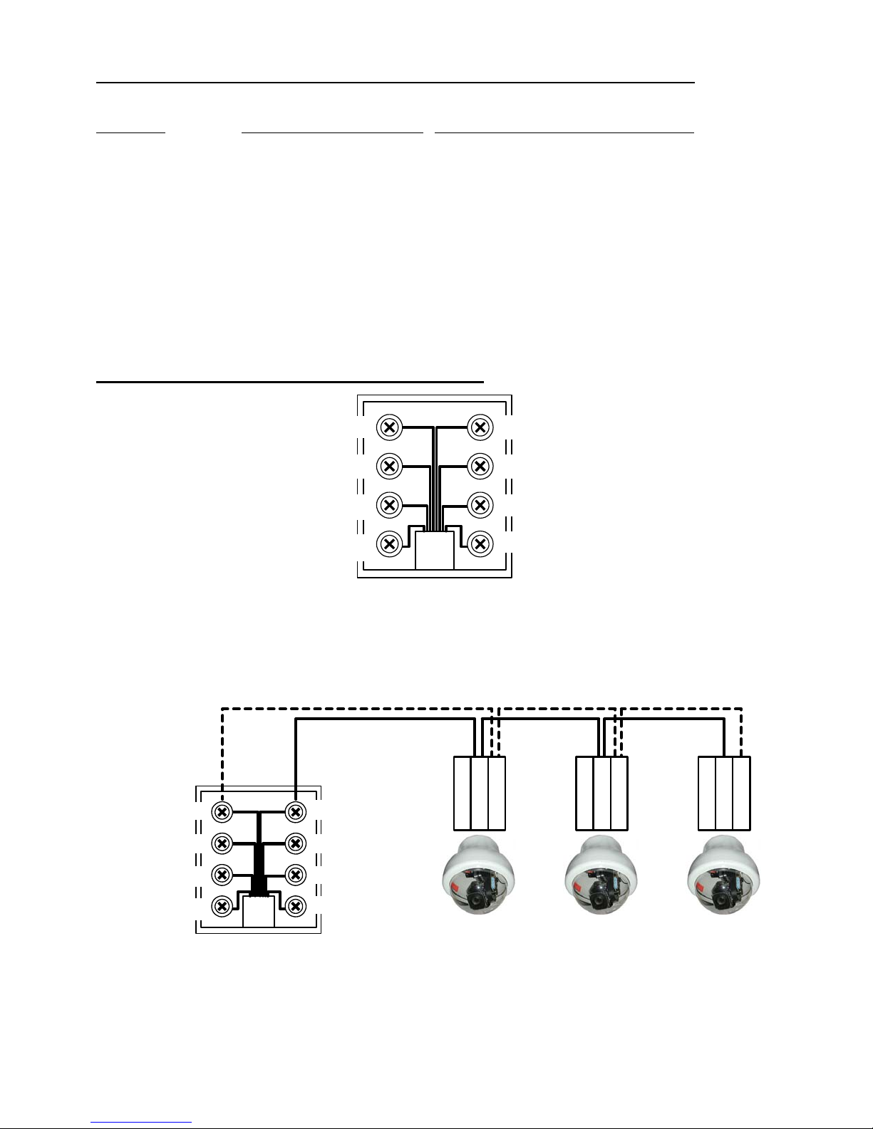
VISTA Coax Extended Commands on the Tx1500Matrix
Supports 86 Presets Presets 1 thought to 88 except 33 & 34
Keyboard VISTA COAX Command Keyboard VISTA COA X Command
91 Preset RUN Learn 1 1 Patrol RUN Tour 1
92 Preset RUN Learn 2 2 Patrol RUN Tour 2
93 Preset Program Learn 1 Iris Open Enter
94 Preset Program Learn 2 Iris Close ESC
1# Enter Dome Menu (min idome) VPD-4WP-P-C/L
1# 1# Enter Dome Menu (VISTA POWER DOME)
DomeMENUPassword“1234”
On the VPD-4WP-P-C/L if you press the Autopan Key nothing will happen until you either:
i) Press the Iris close and it will start a dome scan if saved.
ii) Use the joysti ck and it wi ll go in to the menu Password screen.
RS422 (simplex) TELEMETRY OUT
4 = TxA to Dome RA(+)TxB to Dome RB(-) = 5
TxB to Dome RB(-) = 5
DO NOT USE = 6
DO NOT USE = 7
DO NOT USE = 6
SCREEN = 7
SCREEN = 8
4 = TxA to Dome RA(+)
3 = DO NOT USE
2 = DO NOT USE
3 = DO NOT USE
2 = DO NOT USE
1 = DO NOT USE
G
RAR
N
B
D
G
RAR
N
B
D
G
RAR
N
B
D
SCREEN = 8
RJ45 breakout box
This port provides telemetry control via BBV RS422 (simplex). A Cat 5 RJ45 patch cable and breakout box is used to
connect the VISTA DOME CAMERAS via sin gle twisted pair cable. It is poss ible to either wire the network in a daisy
chained or star configuration using an optional RS422 Starcard.
TX1500 Manual V3.5 Dec 07 Page 21 of 40 MATRIX PROGRAMMING/USER GUIDE
1 = DO NOT USE
Dome 1
Dome 2
Dome 3
Page 22

Telemtry Function
Protcoal BBV coax BBV485 VCL coax Pelco coax VISTA coax VISTA 485 TP
Maximun cable
Distance
1#
2#
3#
4#
250M RG59
500M CT125
REFER TO
RECEIVER MANUAL
REFER TO
RECEIVER MANUAL
REFER TO
RECEIVER MANUAL
REFER TO
RECEIVER MANUAL
1200M
BELDEN 8723
REFER TO
RECEIVER MANUAL
REFER TO
RECEIVER MANUAL
REFER TO
RECEIVER MANUAL
REFER TO
RECEIVER MANUAL
250M RG59
275M CT125
N/A ENTER DOME
N/A 180 FLIP EXIT DOME
N/A N/A AUTOPAN Menu Esc Key no
N/A SOFT RESTART RESET DOME Menu Esc Key
250M RG59
275M CT125
MENU
250M RG59
275M CT125
ENTER DOME
MENU
MENU
1200M
BELDEN 8723
ENTER DOME
MENU
EXIT DOME
MENU
Shift
with Shift
5# N/A N/A N/A N/A N/A Freeze off
6# N/A N/A N/A N/A N/A Freeze on
7# N/A N/A N/A N/A N/A Color Mono
toggle
8# N/A N/A N/A N/A N/A 180 Flip
9# N/A N/A N/A N/A N/A Auto Focus toggle
10# N/A N/A N/A N/A N/A Auto Iris toggle
Number of
Presets Spproted
16 32 99 32 86
1 thought to 88
32
except 33 & 34
GOTO 33
N/A N/A 180 FLIP N/A N/A N/A
PRESET
GOTO 80
PRESET
GOTO 81
PRESET
N/A N/A AUTOFOCUS
N/A N/A N/A
ON
N/A N/A AUTOFOCUS
N/A N/A N/A
OFF
GOTO 91
N/A N/A N/A N/A RUN Learn 1 N/A
PRESET
GOTO 92
N/A N/A N/A N/A RUN Learn 2 N/A
PRESET
GOTO 93
N/A N/A N/A N/A Program Learn 1 N/A
PRESET
GOTO 94
N/A N/A N/A N/A Program Learn 2 N/A
PRESET
GOTO 99
PRESET
Iris Open N/A ENTER WHEN IN
N/A
START
AUTOPAN
THE MENU
START
AUTOPAN
START
AUTOPAN
N/A ENTER WHEN IN
THE MENU
START
AUTOPAN
ENTER WHEN IN
THE MENU
N/A
N/A
Iris Close N/A N/A N/A N/A ESCAPE N/A
TX1500 Manual V3.5 Dec 07 Page 22 of 40 MATRIX PROGRAMMING/USER GUIDE
Page 23
SET PASSWORD
TX1500 version 3.5
Change Pin Number
New Pin Number ******
Confirm Number ******
Download
Upload
Initialise System
Return Exit
The default menu password of 999999 can b e cha ng ed using this screen.
MAKE A NOTE OF THE NEW PIN.
The matrix software version is display ed at the top of the screen.
Select the New Pin Number area and type the new PIN. Move to the Confirm Number area and retype the PIN.
If the numbers match then a confirmation screen is displayed. Select EXIT to return to normal operation.
Upload
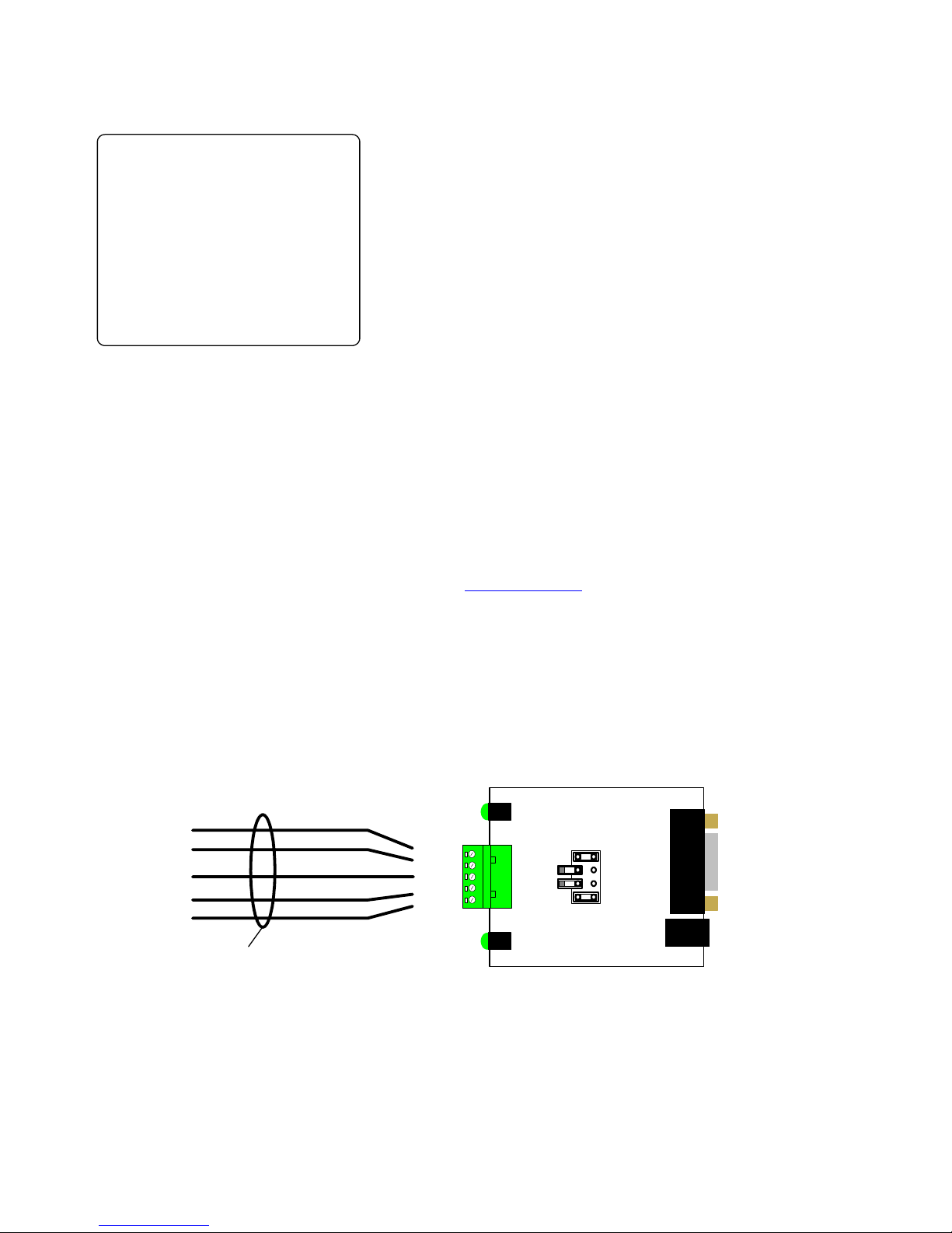
This feature stores the system parameters onto a pc to allow for backup. Data is transferred via the teleme try port.
Connection to a normal serial com port is made through a BBV TXLD. PC application software is called
‘UP_DOWN_GUI’ and is available on the BBV websit e at www.bbvcctv.com
Download
This feature restores the system parameters from a pc. Data is transferred via the telemetry port.
Initialise System:
Cause the entire matrix programmin g to be deleted and default settings used.
This function must be used with great care, as ALL programming will be lost.
TO
TELEMETRY
GREEN/WHITE
PORT
BLUE/WHITE
RJ45 PATCH CABLE
BROWN
GREEN
BLUE
or contact support
Plan view of TXLD PCB
LD2-RX
PCB0313 Iss2
BBV
TO PC
COM PORT
GND
TB/-(OUT)
TA/
+(OUT)
RA/+(IN)
RB/-(IN)
LD1-TX
RX
LO
HI
TX
RS232 in
DB9M
2 = RXD
5 = GND
9V SUPPLY IN
UPLOAD/DOWNLOA D CONNECTION TO PC
TX1500 Manual V3.5 Dec 07 Page 23 of 40 MATRIX PROGRAMMING/USER GUIDE
Page 24

SYSTEM PARAMETERS
Used to program additional settings a s f o llow s:
System Parameters
System Parameters 2
Menu Timeout 60 Seconds
Program Timeout 20 Seconds
Lockout Delay 10 Seconds
Relay 0 Action Latching
Return
System Parameters 2:
Displays the 2
nd
page of system parameters.
Menu Timeout:
Number of seconds of inactivity before the menu is automatically exited. Use +/- to cycle th rough values.
15, 20, 40, 60, 80, 100, 120, 150, 180, 200 or 250 seconds.
Program Timeout:
Number of seconds the keyboard will stay in pr ogra mming mode after th e PROGRAM key is press ed. This is to pre vent
preset positions from being overwr itten accidentally. Use +/- to cycle through values.
15, 20, 40, 60, 80, 100, 120, 150, 180, 200 or 250 seconds. It is recommended that a short time is selected.
Lockout Delay:
Number of seconds that the PTZ control of a camera is locked out after the last movement command. Used to prevent
two keyboards from ‘fighting’ for control of the same camera. Use +/- to cycle through values.
3, 5, 8, 10, 12, 15, 20, 30, 40, 60, 80, 100 or 250 seconds. 10 seconds would be an a ppropriate value.
Relay 0 Action:
Latching – Pressing the keyboard’s TRIANGLE key will toggle the state of the monitor output card relay.
Momentary – The relay will switch whilst the TRIANGLE key is pressed and switch back again when t he key
is released.
TX1500 Manual V3.5 Dec 07 Page 24 of 40 MATRIX PROGRAMMING/USER GUIDE
Page 25

SYSTEM PARAMETERS 2
Used to program additional settings a s f o llow s:
System Parameters 2
Bump Cameras off
Return to patrol off
Priority Keyboard off
Startup Actions
Monitors in sequence
None
Return
Bump Cameras:
Selects the keyboard(s) that will remove the current camera from other monitors when controlled manually. This is to
prevent, for example, public display store monitors from displaying cameras that are following a suspect.
Use +/- to cycle through options:-
Off, Kbd 1, Kbd 2, Kbd 1 + 2, Kbd 3, Kbd 4, Kbd 1 + 2 + 3, Kbd 1+2+3+4
Return to patrol:
If set to on, the current camera will start a preset patrol 1, if supported, when another camera is selected. This is useful
for a system that has several cameras that should run preset patrols all the time that they are not controlled manually.
Priority Keyboard:
A keyboard can be set that can take control of cameras at any time and is not locked out by other keyboards.
Startup Actions – Monitors:
This option allows selected monitors to resume sequence should the system power fail and restore. Use +/- to cycle
between the monitor choices.
None, 8, 78, 678, 5678, 45678, 345678, 2345678, or 12345678.
TX1500 Manual V3.5 Dec 07 Page 25 of 40 MATRIX PROGRAMMING/USER GUIDE
Page 26
UP-THE-COAX RECEIVER SPECIFIC PROGRAMMING
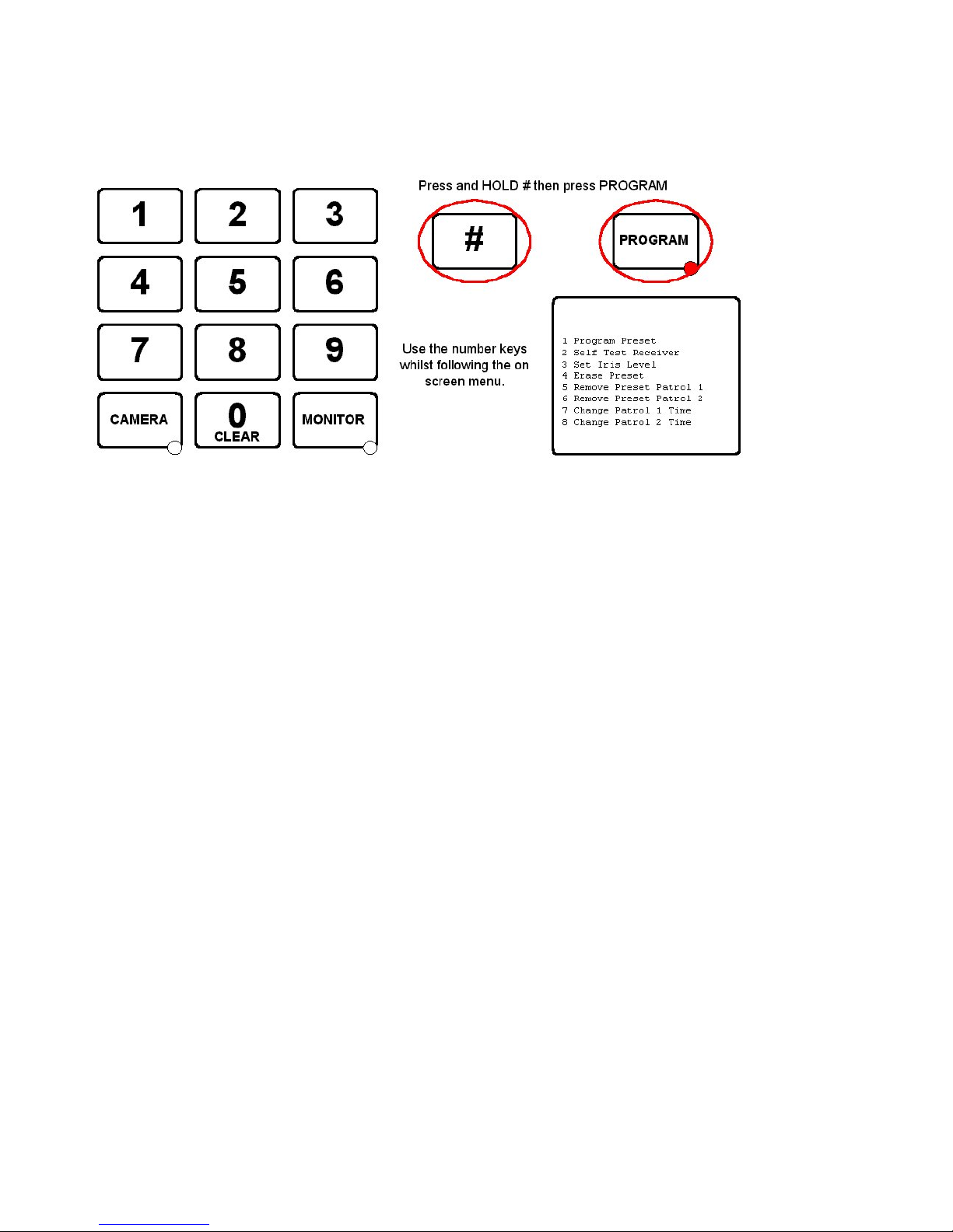
To program specific features of Rx100/200/300/400P/400DC up-the-coax receivers, the c amera type must be set to
BBV COAX. Press and hold the ‘#’ key an d tap the PROGR AM ke y to disp lay the option s. The PROGRAM ke y must be
enabled in the keyboard using SW1 switch 8 O N which is the factory default setting .
1 Program Preset 01-16
Enter 01 – 16 to program this preset position.
This is a legacy function to program a preset position and the preferred method is described on page 25.
2 Self Test Receiver
This will start the remote self test function, i.e. left/right/up/down etc on BBV up-the-coax receivers only.
3 Set Iris Level
Used with Rx300 Rx400P and Rx400DC to set the iris override output if fitted.
4 Erase Preset 01-16
Used to erase a preset from an RX100, RX4 00 P or RX400DC. Enter 01 – 16 to erase the pre set position.
5 Remove Preset Patrol 1
Enter 01 – 16 to remove the preset from preset patrol 1 with RX100, RX400P and RX400DC receivers
6 Remove Preset Patrol 2
As above but removes the preset positi on from patrol 2
7 Change Patrol 1 Time
Used to set the dwe ll time for patrol 1. 01 = RANDOM, 02 = 12 se conds, 03 = 24 sec onds etc up to 16 = 180 seconds
when used with Rx100, Rx400P an d Rx400DC receivers.
8 Change Patrol
As above but relates to preset patrol 2.
The menu will timeout and the PROGRAM key LED will turn OFF after several seconds to prevent accidental
reprogramming of the receiv er.
TX1500 Manual V3.5 Dec 07 Page 26 of 40 MATRIX PROGRAMMING/USER GUIDE
Page 27
TX1500 USER GUIDE
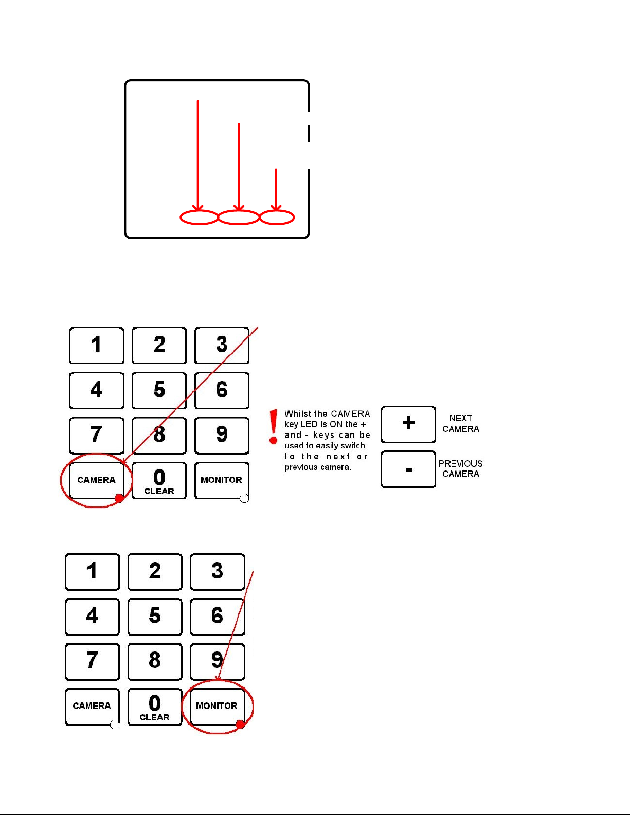
Monitor Number
Current Camera Number
Keyboard Number
driving camera
Mon 1 Cam 01 Kbd 1
Monitor outputs 5,6,7 & 8 are not equipped with On Screen Displays and are generally used as spot, park or
public display monitors.
SELECTING A CAMERA
Use the number keys followed by the CAMERA key.
If the keyboard AND monitor are allowed to display the camera then the
current monitor will now display this camera.
If not then the command is ignored.
SELECTING A MONITOR
Use the number keys followed by the MONITOR key.
If the keyboard is not allowed to control this monitor then the command
is ignored.
Otherwise the keyboard can now control the camera displayed on the
new monitor
Monitor outputs 1,2,3 & 4 have an O n Screen
Display as shown on the left.
The Monitor number along with current Ca mer a
number is shown permanently.
Kbd is displayed whenever a keyboard is
driving a camera.
TX1500 Manual V3.5 Dec 07 Page 27 of 40 MATRIX PROGRAMMING/USER GUIDE
Page 28
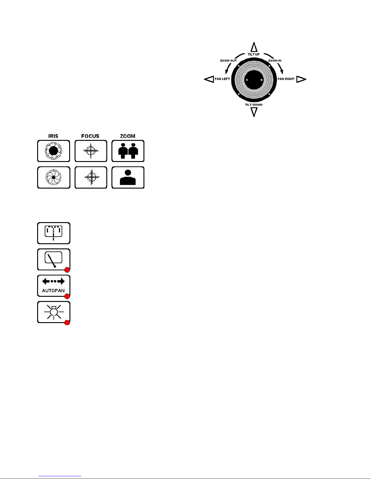
MOVING A CAMERA
JOYSTICK
The joystick is used to pan and tilt the camera and drive the lens
zoom.
Moving the joystick left and right will pan the camera and moving
the joystick up and down will tilt the camera.
Rotating the joystick knob clockwise will zoom the lens IN and rotating
the knob anti-clockwise will zoom the lens OUT.
The joystick gives variable speed control
LENS KEYS
These keys are used to zoom an d focus the lens and alter the iris if that
function has been provided.
Press a key for the desired function an d re lease to stop.
AUXILIARY OUTPUTS
The WASH key is used to wash the camera housing’s glass if the feature has been provided.
The WIPER key is used to toggle the camera ho using’s wiper ON/OFF
The function of the AUTOPAN key will vary depending upon the camera being controlled but mainly is
used to make the camera either pan from end stop to end stop or to run a preset patrol. Moving the
joystick left or right will turn autopan off.
The LIGHTS key is used to toggle any lights ON/OFF
TX1500 Manual V3.5 Dec 07 Page 28 of 40 MATRIX PROGRAMMING/USER GUIDE
Page 29
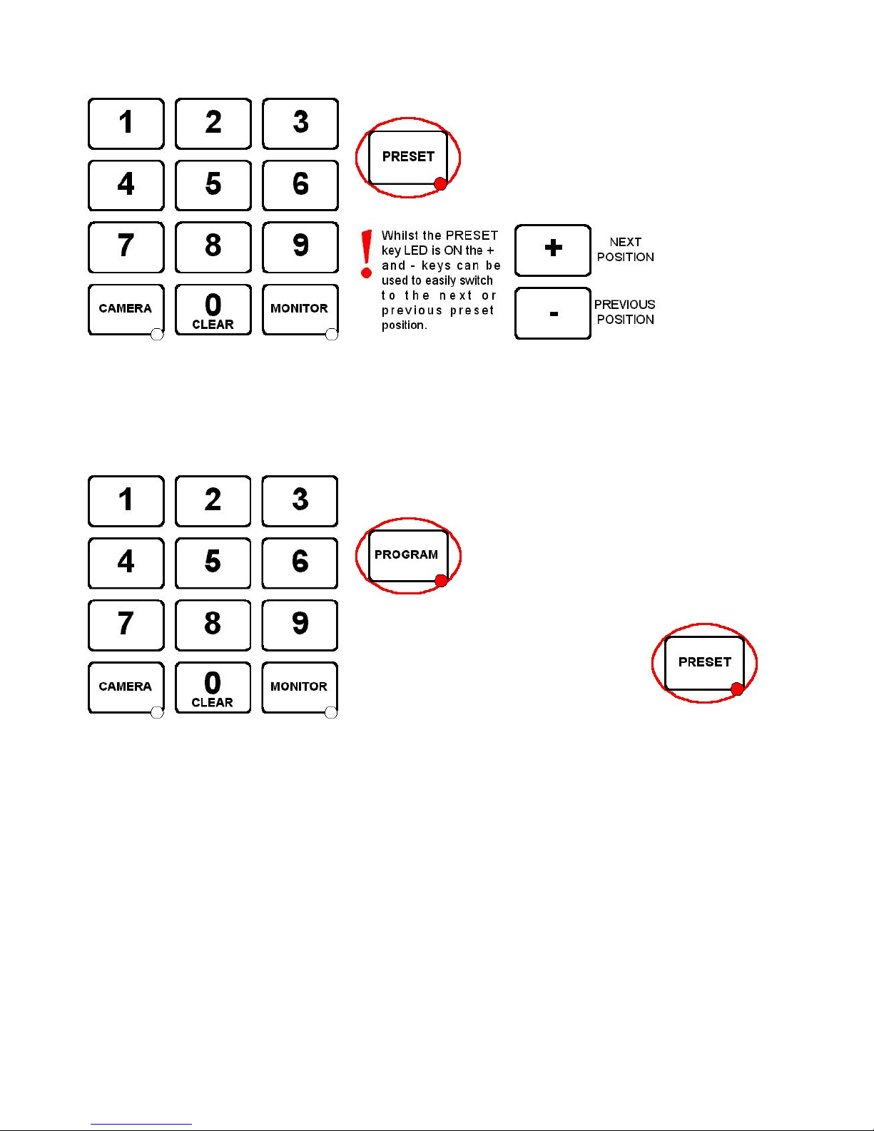
GOTO PRESET POSITION
Use the number keys followed by the PRESET key.
Preset positions are only available on moving cameras that are equipped for presets. Most will accept pr esets 1 – 16
although the TX1500 supports preset positions up to 99. This should be checked with your installing company.
PROGRAMMING A PRESET POSITION
Press the PROGRAM key to turn the PROGRAM key LED ON. The unit is
now in preset programming mode.
If the LED doesn’t light then this keyboar d has been
prevented from programming presets by the
installation company.
Use the number keys followed b y the PRESET key
to program the new preset position.
TX1500 Manual V3.5 Dec 07 Page 29 of 40 MATRIX PROGRAMMING/USER GUIDE
Page 30
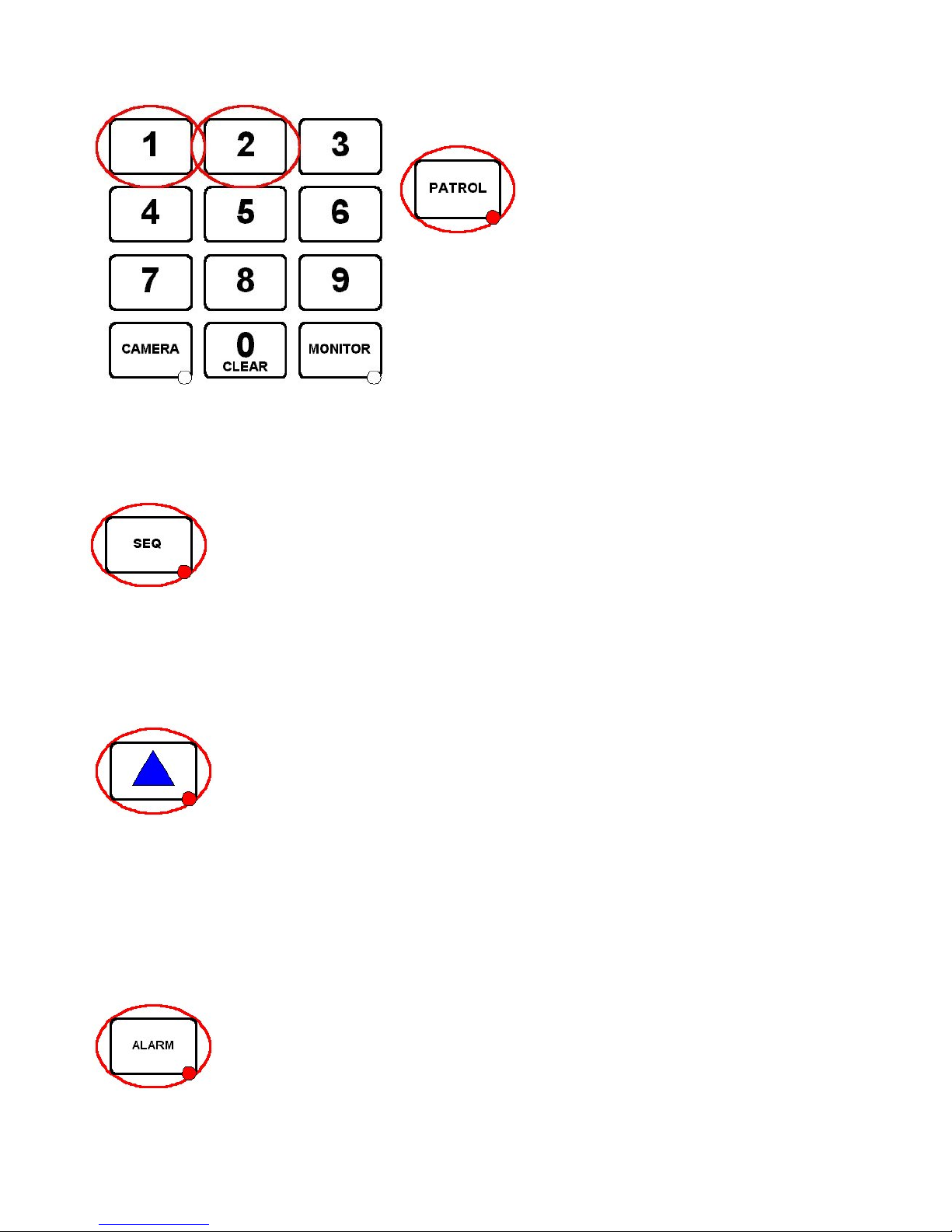
STARTING A PRESET PATROL
Press either 1 or 2 followed by the PATROL key.
The PATROL key LED will be ON whilst the current camera is running a
preset patrol.
To stop the camera from patrolling, move the joystick. The PATROL key
LED will now be OFF.
As with presets, patrols are only availab le on moving cameras that are equipped for presets. Certain dome camera s
offer enhanced patrol features that will be covered in the product addendum sheet for each specific dome type.
STARTING A MONITOR CAMERA SEQUENCE
Pressing the SEQ key will start a camera switching sequence on the current monitor. The SEQ key
LED indicates if the current monitor is running a sequence.
Each monitor can sequence individually and simultaneously.
The monitor sequence is programmed by the installation company using the system conf iguration menu.
To stop the sequence either press the SE Q ke y again to toggle the LED OFF or select another camera.
TRIANGLE / RELAY KEY
Use the TRIANGLE key to operate the TX1500 change over relay on the monitor out card. This
can be used for a variety of purposes. Your installation company will inform you of the specific
function for your site.
The relays on each alarm card can also be switched as follows:
2 TRIANGLE – relay 2 alarm card 1
3 TRIANGLE – relay 1 alarm card 2 4 TRIANGLE – relay 2 alarm card 2
5 TRIANGLE – relay 1 alarm card 3 6 TRIANGLE – relay 2 alarm card 3
7 TRIANGLE – relay 1 alarm card 4 8 TRIANGLE – relay 2 alarm card 4
9 TRIANGLE – relay 1 alarm card 5 10 TRIANGLE – relay 2 alarm card 5
11 TRIANGLE – relay 1 alarm card 6 12 TRIANGLE – relay 2 alarm card 6
ALARM KEY
If the system has been configured for KEY PRESS alarms by the ins tallation company, follow ing a
site alarm the ALARM key LED will be ON, the alarm monitor will display ‘alarm’ and the alarm
keyboard will beep.
The alarm is acknowledged by pressing the ALARM key. The alarm monitor/s will display the
camera/s programmed for this alarm.
TX1500 Manual V3.5 Dec 07 Page 30 of 40 MATRIX PROGRAMMING/USER GUIDE
Page 31

TX1500/KBD - System Keyboard
This keyboard provides control of the system and any cameras connected to the matrix. The keyboard
communicates through an RJ45 connector using BBV TX1500 protocol at 9600 baud on an RS422 link.
An internal 8 way DIP switch is used to set the keyboard address, RS422 termina tion and PROGRAM key
enable/disable.
Each keyboard must have a unique address between 1 and 4. Keyboards sharing the same
address will not be recognised by the matrix and unpredictable operation will occur.
Keyboard switch settings
ON
SW 1-2 Keyboard Address
SW 3-5 OFF
SW 6-7 ON = BBUS Termination for end of line
SW 8 ON = PROGRAM key enable
78123 546
Keyboard Address SW1 SW2
1 OFFOFF
2 ON OFF
3 OFFON
4 ON ON
Joystick Calibration Procedure
If the joystick needs recalibration then fo llo w instructions below:-
1.Power down the keyboard for 30 seconds.
2.Press and hold both the 1 and TRIANGLE keys and power up the keyboard.
3.The TRIANGLE led will then flash indicating that the keyboard is in calibration mode.
4.Press 5 to set the joystick zero position.
5.Move the joystick fully UP and ho ld in this position and press 2
6.Move the joystick fully DOWN and hold in this position and press 8
7.Move the joystick fully LEFT and hold in this position and press 4
8.Move the joystick fully RIGHT and hold in this position and press 6
9.Rotate the joystick knob fully clockwise (ZOOM IN) and hold in this position and press ZOOM IN
10.Rotate the joystick knob fully anti -clo ckwise (ZO O M OUT) and hold in this position and press ZOOM OUT
11.Calibration is then complete. Power down the keyboard for 30 seconds before powering up.
Check that the TRIANGLE led is not flashing after power up if it is then power down again for 30
seconds.
The keyboard requires 9Vac/dc supply, minimum current of 100mA. A single keyboard can be supplied through a
patch cable from the matrix. Multipl e or remo t e key boards will need separate power supplies, which are supp lie d
as standard with each keyboard. Additional po wer supp lie s can b e obtained from BBV.
TX1500 Manual V3.5 Dec 07 Page 31 of 40 TX1500/KBD SYSTEM KEYBOARD
Page 32
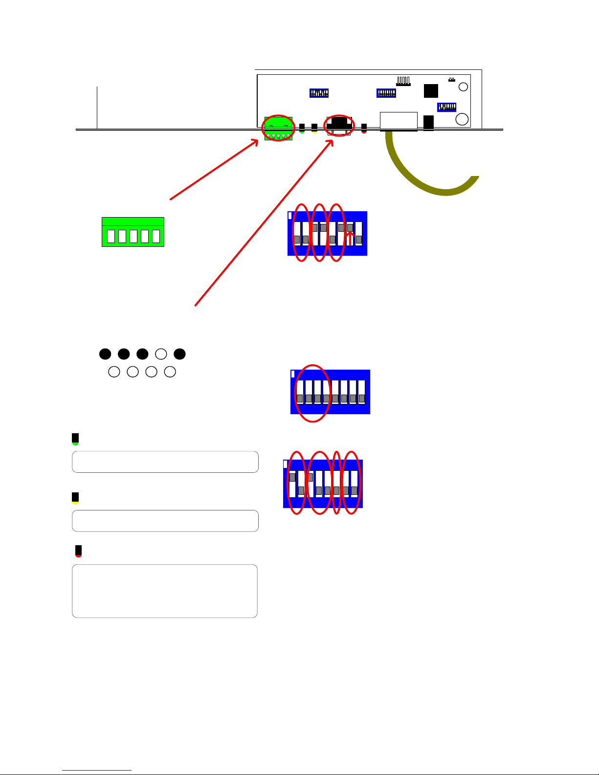
TX1500/BBUS-IF Interface switch settings
TX1500 BBUS Interface
RS485/422
5 RB/-(IN)
4 RA/+(IN)
3 TA/+(OUT)
2 TB/-(OUT)
1 GND
RS232
Chassis Mount DB9 Male
+V OUT
RS232 IN
RS232 OUT
1 2 3 4 5
7 8 96
GND
LED guide
02005 Iss 2
SW1
LD1
LD2
SW1 Settings
ON
7812 3 546
SW3 - Mode
ON
SW3
B-BUS
LD3
SW4
POWER
RJ45 to TX1500 BBUS
1/2 = BBUS termination
Must be ON only when the interface is at the
end of line.
Default = OFF
3/4 = RS485 termination
Must be ON only when the interface is at the
end of line. Default = ON.
5/6 = RS232 or RS485 selection.
SW1/5 SW1/6 Input
OFF OFF None
ON OFF RS485
OFF ON RS232 (Default)
ON ON DO NOT USE
7 = MUST BE ON
8 = NOT USED
SW3/1 Select mode
OFF BBUS Mode - RS232 control
ON Remote keyboard mode
78123 546
Running Tx1500 keyboard over a RF link,
fibre or other network.
GREEN LD1
Flashes when the interface sends an LED
status to the RS232 port.
YELLOW LD2
Flashes when interface receives a command
from the RS232 port.
RED LD3
BBUS comms status.
OFF = Unit de-powered
ON = Unit Powered but not communicating
with the Tx1500.
Pulsing Very Fast = Comnunicating correctly.
SW4 Settings
ON
1/2 = BBUS Address
SW4/1 SW4/2 Addr Keyboard No
OFF OFF 0 1
ON OFF 1 2 (Default)
OFF ON 2 3
ON ON 3 4
3/4/5 = Default Monitor Selection
SW4/3 SW4/4 SW4/5 Monitor
7123 5468
OFFOFFOFF1
ON OFF OFF 2 (Default)
OFF ON OFF 3
ON ON OFF 4
OFF OFF ON 5
ON OFF ON 6
OFFONON7
ON ON ON 8
6 = Control Protocol Selection
SW4/5 Protocol
OFF TX1000 (Default)
ON T X1500
7/8 Remote Tx1500 keyboard modes
SW4/7 SW4/8 Mode
OFF OFF Normal mode (SW3/1 OFF)
ON ON M atrix E nd (SW3/1 ON)
OFF ON Keyboard End (SW3/1 ON )
7/8 Variable/Fixed speed when in normal mode
OFF OFF Variable speed
ON O F F Fixed speed - High Speed (8)
ON O N Fixed speed - Low speed (2)
TX1500 Manual V3.5 Dec 07 Page 32 of 40 TX1500/BBUS-I/F INTERFACE
Page 33
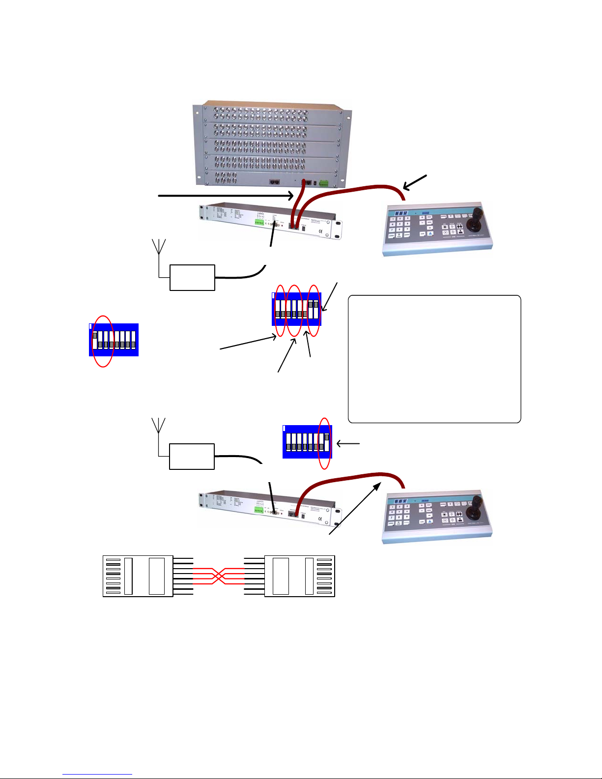
BBUS I/F FOR R EM O TE T X1500 KEYBO ARD
TX1500 MA TRIX
Standard RJ45
CAT5 patch cable
BBUS I/F
RS232-9600,N,8,1
RF Link
SW 3 setting
ON
12 3456 78
ON - Remote keyboard mode
SW3/1-4 must be as shown at both ends.
1 & 2 selects keyboard address
3,4 & 5 selects monitor
SW4 Setting
ON
12 3456 78
SW4 Setting
ON
6 not important
Standard RJ45
CAT5 patch cable
TX1500 KEYBOARD
7 & 8 ON at MATRIX END
The BBUS Interface at the keyboard end of the link
sends a stop command if the joystick/lens is not
active every 5 seconds. This is used to help with
links that could lose data.
If the link is bi-directional, then the following led flash
sequ e nce will be se e n .
1. KEYBOARD END GREEN (data out)
2. MATRIX END YELLOW (data in)
3. MATRIX END GREEN (data out)
4. KEYBOARD END YELLOW (data in)
If the link is a simplex link then just steps 1,2 and 3
will b e seen as the d a ta w ill g et b a c k into th e
KEYBOARD end interface.
1-7 OFF, 8 ON at KEYBOARD END
RF Link
12 3456 78
RS232-9600,N,8,1
BBUS I/F
RJ45 Cable with 3 & 4 swapped and 5 & 6 swapped
8
1
TX1500 KEYBOARD
(Addressed as 0)
(SW1-5 O F F)
1
3 - 4
8
4 - 3
5 - 6
6 - 5
TX1500 Manual V3.5 Dec 07 Page 33 of 40 TX1500/BBUS-I/F INTERFACE
Page 34
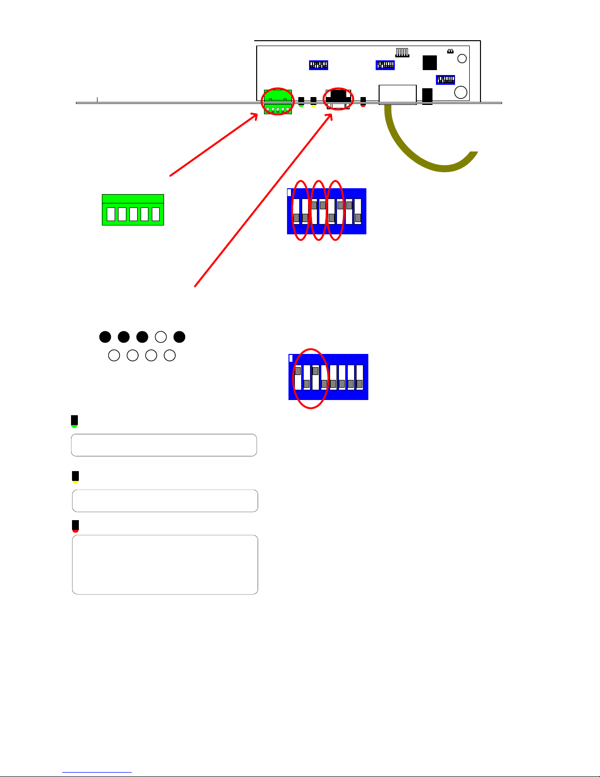
TX1500 BBUS Interface
FBMCPU MODE-8 KEYBOARDS
RS485/422
5 RB/-(IN)
4 RA/+(IN)
3 TA/+(OUT)
2 TB/-(OUT)
1 GND
RS232
Chassis Mount DB9 Male
+V OUT
RS232 IN
RS232 OUT
1 2 3 4 5
7 8 96
GND
02005 Iss 2
SW1
LD1
LD2
SW1 Settings
ON
7812 3 546
SW3 - Mode
ON
SW3
B-BUS
LD3
SW4
POWER
RJ45 to FBMCPU BBUS
1/2 = BBUS termination
Must be ON only when th e interface is at the
end of line.
Default = OFF
3/4 = RS485 termination
Must be ON only when th e interface is at the
end of line. Default = ON.
5/6 = RS232 or RS485 selection.
SW1/5 SW1/6 Input
ON OFF RS485
OFF ON RS232
ON ON DO NOT USE
7 = MUST BE ON
8 = NOT USED
SW3 Select mode
1-4 set the switches as shown to select FBMCPU
mode which allows 8 keyboard addresses
LED guide
7812 3 546
GREEN LD1
Flashes when the interface sends an LED
status to the RS232 port.
YELLOW LD2
Flashes when interface receives a command
from the RS232 port.
RED LD3
BBUS comms status.
OFF = Unit de-powered
ON = Unit Powered but not communicating
with the FBMCPU.
Pulsing Very Fast = Comnunicating correctly .
This mode is to allow the BBUS/I-F to connect to the processor of our larger FBM matrix system. The FBM matrix
allows up to 8 keyboard positions where the standard TX1500 mode allows 4 addresses.
If the BBUS/I-F is used with a TX 1500 th en DO NO T us e this mode.
TX1500 Manual V3.5 Dec 07 Page 34 of 40 TX1500/BBUS-I/F INTERFACE
Page 35

TX1500 control protocol via the TX1500/BBUS/I-F
The ZP-TX1500 matrix can be controlled using a simple serial protocol with the use of a TX1500/BBUS/I-F
interface. The protocol is described on the following pages.
Baud settings: 9600,N,8,1. Timing is not critical.
Function String Notes
SELECT MONITOR @2,M <CR> M = monitor number (1 - 8)
SELECT CAMERA @3,C <CR> C = camera number (1 - 96)
PAN RIGHT @5,2 <CR>
PAN LEFT @5,3 <CR>
TILT UP @5,4 <CR>
TILT DOWN @5, 5 <CR>
ZOOM IN @5,6 <CR>
ZOOM OUT @5,7 <CR>
FOCUS FAR @5,8 <CR>
FOCUS NEAR @5,9 <CR>
IRIS CLOSE @5,10 <CR>
IRIS OPEN @5,11 <CR>
WASH ON @5,12 <CR>
WIPER ON @5,19 <CR>
LAMPS ON @5,21 <CR>
STOP PAN RIGHT @6,2 <CR>
STOP PAN LEFT @6,3 <CR>
STOP TILT UP @6,4 <CR>
STOP TILT DOWN @6,5 <CR>
STOP ZOOM IN @6,6 <CR>
STOP ZOOM OUT @6,7 <CR>
STOP FOCUS FAR @6,8 <CR>
STOP FOCUS NEAR @6,9 <CR>
STOP IRIS CLOSE @6,10 <CR>
STOP IRIS OPEN @6,11 <CR>
STOP WASH ON @6,12 <CR>
STOP WIPER ON @6,19 <CR>
STOP LAMPS ON @6,21 <CR>
STOP PAN/TILT/LENS @6,22 Stops all pan/tilt and lens movement
PAN/TILT SPEED @7,P, T <CR>
GOTO PRESET @8,P <CR> P = preset number (1-99)
PROGRAM PRESET @9,P <CR> P = preset number (1-99)
START PATROL 1 @10 <CR>
START AUTOPAN @12 <CR>
START MONITOR
SEQUENCE
STOP MONITOR
SEQUENCE
@25,0 <CR> Same as hold off
@25,1 <CR> Same as hold on
P=Pan & T=Tilt speed in the range 0 - 15
0 = slowest, 15 = fastest
TX1500 Manual V3.5 Dec 07 Page 35 of 40 TX1500/BBUS-I/F INTERFACE
Page 36

X = 0 – 12
0 = Tx1500 relay
1 – 2 = relays 1 & 2 of alarm card 1
Relay ON (Triangle Key) @50,X<CR>
3 – 4 = relays 1 & 2 of alarm card 2
5 – 6 = relays 1 & 2 of alarm card 3
7 – 8 = relays 1 & 2 of alarm card 4
9 – 10 = relays 1 & 2 of alarm card 5
11 – 12 = relays 1 & 2 of alarm card 6
Relay OFF @51, X <CR> X = As above
HASH command @52,X<CR>
X = hash number – see Tx1500 for specific
hash commands.
Send Single Key Press @53,0<CR> ‘0’ Key
@53,1<CR> ‘1’ Key
@53,2<CR> ‘2’ Key
@53,3<CR> ‘3’ Key
@53,4<CR> ‘4’ Key
@53,5<CR> ‘5’ Key
@53,6<CR> ‘6’ Key
@53,7<CR> ‘7’ Key
@53,8<CR> ‘8’ Key
@53,9<CR> ‘9’ Key
@53,10<CR> ‘CAMERA’ key
@53,11<CR> ‘MONITOR’ key
@53,12<CR> ‘CLEAR’ key
@53,13<CR> ‘+’ key
@53,14<CR> ‘-‘ key
@53,15<CR> ‘PRESET’ key
@53,16<CR> ‘PATROL’ key
@53,17<CR> ‘SEQ’ key
@53,18<CR> ‘RELAY/TRIANGLE’ key
@53,19<CR> ‘ALARM’ key
@53,21<CR> ‘PROGRAM’ key
@53,22<CR> TX1500 MENU ACCESS
Display current Info @54<CR>
Output current camera, monitor & lights
status
All characters shown are the actual ASCII characters that should be sent. Two or three digit numbers will be sent
using either two or three characters.
All commands are terminated with a <CR> = 0x0d or decimal 13
TX1500 Manual V3.5 Dec 07 Page 36 of 40 TX1500/BBUS-I/F INTERFACE
Page 37

Examples
Select camera 1 onto monitor 4
@2,4 <CR> Complete HEX byte string 0x40 0x32 0x2c 0x34 0x0 d
@3,1 <CR> 0x40 0x31 0x2c 0x31 0x0d
Once the monitor is selected, any subsequent camera selects relate to this monitor ie to now select camera 16
send the following:
@3,16 <CR>
The current camera can then be controlled using the @5 and @6 commands.
@5 commands are used to start a function and @6 commands are used to stop a function. Only a single function
can be controlled with each command
To Pan Left, Tilt Up and Zoom in, send the following:
@5,3 <CR>
@5,4 <CR>
@5,6 <CR>
Pan and Tilt speeds are sent using the @7 command. 16 speed are supported, 0 being the slowest speed up to
15 as the fastest.
If no speed command is sent following a @5 command then a speed of 1 will be assumed. This prevents the
head from ‘jerking’ on movement start.
Speed Examples
Move Left at increasing speeds
@5,3 <CR> Start Panning Left
@7,1,1 <CR> Slow Pan Speed
@7,5,1 <CR> Increased Pan Speed
@7,10,1 <CR> Even Higher Pan Speed
@7,15,1 <CR> Full Pan Speed
To stop movement in a direction send a @6 command followed by pan/tilt speed 0
To stop moving left send
@6,3 <CR>
@7,0,0 <CR>
Selecting a new camera whilst the current camera is moving will cause the current camera to stop moving before
selecting the new camera.
Responses sent from the TX1500 BBUS Interface
Each response is followed by CR/LF.
On power up the following message is sent:: TX1500 BBUS I-F V6
After each successfully received command the interface responds with OK and ERR followed by reason if the
command or a parameter is invalid.
After a @54<CR> command or if the current monitor, camera or LED status changes the following message is
send. M1,C01 0000000
M = The monitor number, 1-8
C = The camera number, 1-96
The next 7 characters represent the LED st atus, 1 if the LED is ON, 0 is OFF as shown left to ri gh t.
LIGHTS, AUTOPAN, WIPE, ALARM, TRIANGLE, SEQ, PATROL
EG monitor 2 showing camera 45 which is running a pat rol with the lights on.
M02,C45 1000010
If implementing software to cont ro l th e ZP-TX1500 please check for a later version of t he control protocol first.
TX1500 Manual V3.5 Dec 07 Page 37 of 40 TX1500/BBUS-I/F INTERFACE
Page 38

NOTES
TX1500 Manual V3.5 Dec 07 Page 38 of 40 TX1500/BBUS-I/F INTERFACE
Page 39

NOTES
TX1500 Manual V3.5 Dec 07 Page 39 of 40 TX1500/BBUS-I/F INTERFACE
Page 40

BBV products
Description
Single camera desktop telemetry transmitter with coax & 20mA
TX400
TX400DC
TX1000 MK2
TX1500
FBM range
All RX receivers below are powered by 230V ac or optional 110V or 24V ac.
RX100
RX200
RX300
RX400P
RX400DC
RX45X (AC)
RX55X (DC)
Multi serial protocol
and up-the-coax
telemetry receivers
telemetry, Pan/Tilt/Lens, Lights, Wash, Wipe, Autopan, 8 presets,
preset patrol.
As TX400 including joystick for variablel Pan/Tilt control.
Option of RS485 telemetry output.
8 or 16 camera, 2 monitor telemetry transmitter. Up to 2
keyboards. BBV up-the-coa x and RS422 s tandard with options for
alarm inputs and 20mA telemetry.
Mid size matrix 16 – 96 camera, 8 monitor. Up to 4 control
positions (keyboard & remote c ontrol) options for alarms, remote
control, BBV up-the-coax and RS485 telemetry.
Large size matrix. Configurable up to 4096 cameras and 64
monitor outputs. Up to 8 control positions (keyboard & remote
control) options for alarms, remote control RS485 telemetry with
various options. Please call to discuss require m en ts.
Dome Interface to drive a large library of dome cameras. BBV upthe-coax and 20mA telemetry. Mains or plugtop supply.
AC receiver for Pan only heads or static cameras,
Wash/Wipe/Lights. BBV up-the-coax and 20mA telemetry.
AC receiver for Pan/Tilt/Zoom/Focus/Iris Override and 1 Auxiliary
output. BBV up-the-coax and 20mA telemetry.
AC full function receiver. PTZFI 4 Auxiliary outputs, 16 presets.
BBV up-the-coax and 20mA telemetry.
24Vdc high/variable speed receiver. 16 presets, 8 local alarm
inputs,3 Auxiliary outputs. BBV up-the-coax and 20mA telemetry.
Multiple RS485/422 and up-the-coax controllable AC and DC receivers.
PTZFI control, 32 presets, preset patrol, 8 local alarm inputs, 12V 500mA
supply output. OSD for remote setup, test & diagnost ics. 3 Aux. outputs
RX55X or 4 Aux. outputs RX45X.
Optional Privacy board.
BBV RS422, UP-THE-COAX, 20mA current loop
BAXALL STANDARD & ALTERNATE UP-THE-COAX,
DENNARD RS422/485, PELCO P/D RS422/485,
PHILIPS/BOSCH RS422/485 (OPTIONAL BI-PHASE INPUT),
MOLYNX RS422/485, SENSORMATIC/AD RS422,
VCL/HONEYWELL RS422/485, VICON RS422
MEYERTECH, CIRRUS AUDIO MONITORING
RX450/550
STARCARD
STARCARD/CONVERTER
CTI/16
ACCESSORIES
See all our products @ www.bbvcctv.com
TX1500 Manual V3.5 Dec 07 Page 40 of 40 TX1500/BBUS-I/F INTERFACE
PANASONIC RS485 Protocol only version of RX45X/55X.
8 * RS485 output, 2 wire simples RS422, 4 wire full-duplex
RS422, 2 wire half-duplex RS485.
Option STARCARD/CONVERTER offering protocol
conversion to drive an increasing range of 3
Multi-protocol serial converter that gives up-the-coax control
to 16 cameras. BBV RS422, Dennard RS485, Pelco P, Pelco D,
Philips/Bosch RS485/232, VCL RS485, Sensormatic RS422,
Molynx, Vicon
TxLD (bidirectional RS422-RS232 conv erte r)
98005 (bidirectional 20mA-RS 23 2 con verter)
rd
party protocols.
 Loading...