

Page 1
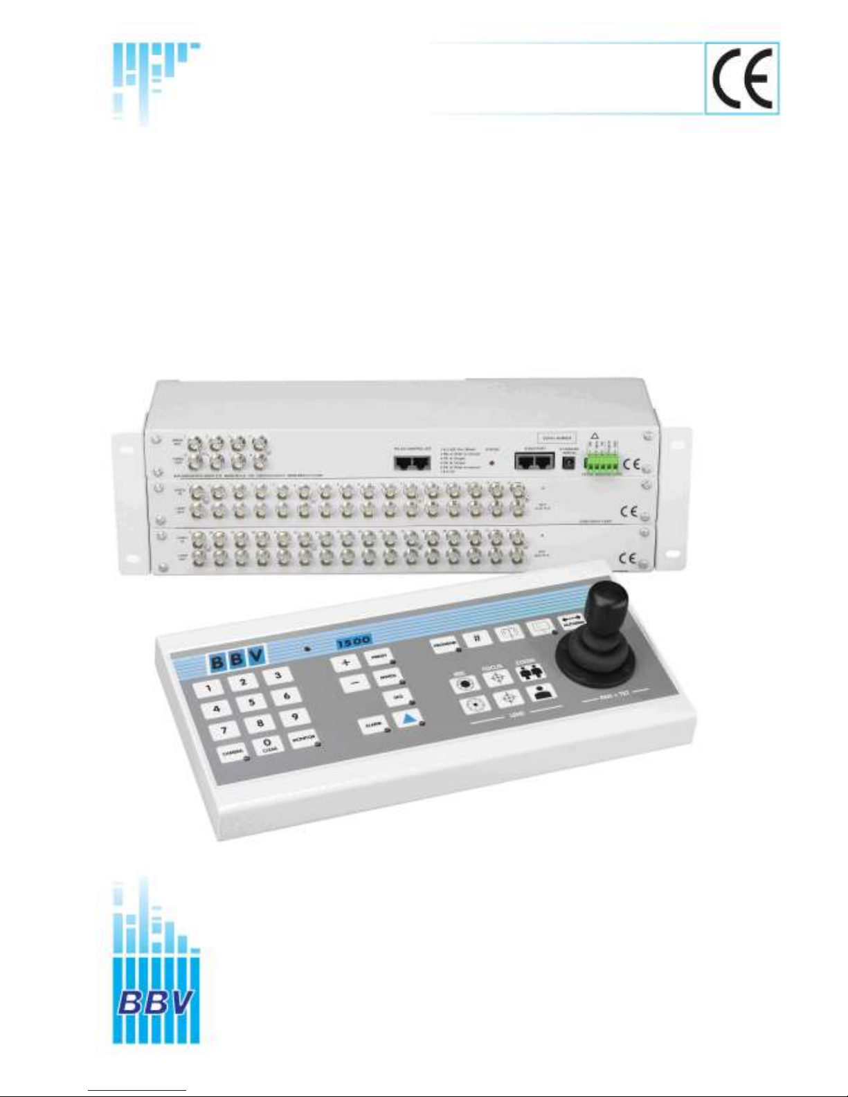
TX1500 Matrix, TX1500 Keypad,
And TX1500/AL16
Building Block Video Ltd.,
17 Apex Park
Diplocks Industrial Estate,
Hailsham, East Sussex, BN27 3JU UK.
Tel: +44 (0)1323 842727
Fax: +44 (0)1323 842728
Support: +44(0)1323 444600
Web Site: http://www.bbvcctv.com
Installation
Guide
Page 2

TX1500 Manual V4.1 Oct 2011.doc Page 2 of 32 TX1500 MATRIX
Contents
Unpacking 3
Safety Precautions 3
System Components 3
Description 4
TX1500 components 4
Product Codes 4
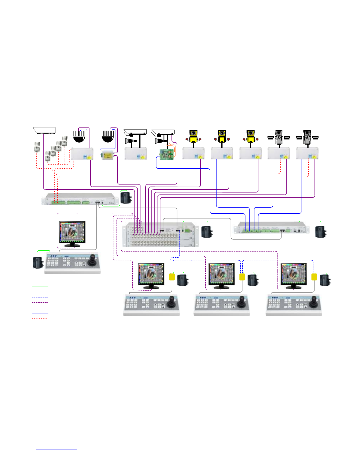
TX1500 System Example 5
BBUS control bus 6
BBUS example wiring 7
RS422 Telemetry port 8
RS422 wiring diagrams 8, 9
Video Input Card 10
Monitor Output Card 11
Matrix ALARM 00 & relay connector 11
96 Camera subrack wiring 12
Matrix Dianostics 13
TX1500/AL16 16 Input Alarm Card 14
Configuring the TX1500 15
System Basics 16
Access Tables 17
Alarm Menus 18
Sequences 19
Camera Types 20
Vista Extended Commands 21
Telemetrey Functions 22
Set Password 23
System Parameters 24
System Parameters 2 25
Up-the-coax receiver programming 26
TX1500 USER GUIDE 27
Selecting a Camera 27
Selecting a Monitor 27
Moving a Camera 28
Lens Keys 28
Auxiliary Outputs 28
Go to Preset Position 29
Programming a Preset Position 29
Starting a Preset Patrol 30
Starting a Monitor Sequence 30
Triangle/Relay Key 30
Alarm Key 30
TX1500/KBD System Keypad 31
Page 3
TX1500 Manual V4.1 Oct 2011.doc Page 3 of 32 TX1500 MATRIX
UNPACKING
Inspect the packaging for signs of damage. If damage has occurred, advise the carriers and/or the suppliers
immediately. Unpack the units carefully and check that all the items are present and correct.
SAFETY PRECAUTIONS
All normal safety precautions as laid down by British Standards and the Health and Safety at Work Act (or the relevant
National safety legislation if installing in a country outside the U.K.) should be observed, and servicing should be
referred to qualified service personnel.
SYSTEM COMPONENTS
Each complete system will comprise of at least the following:
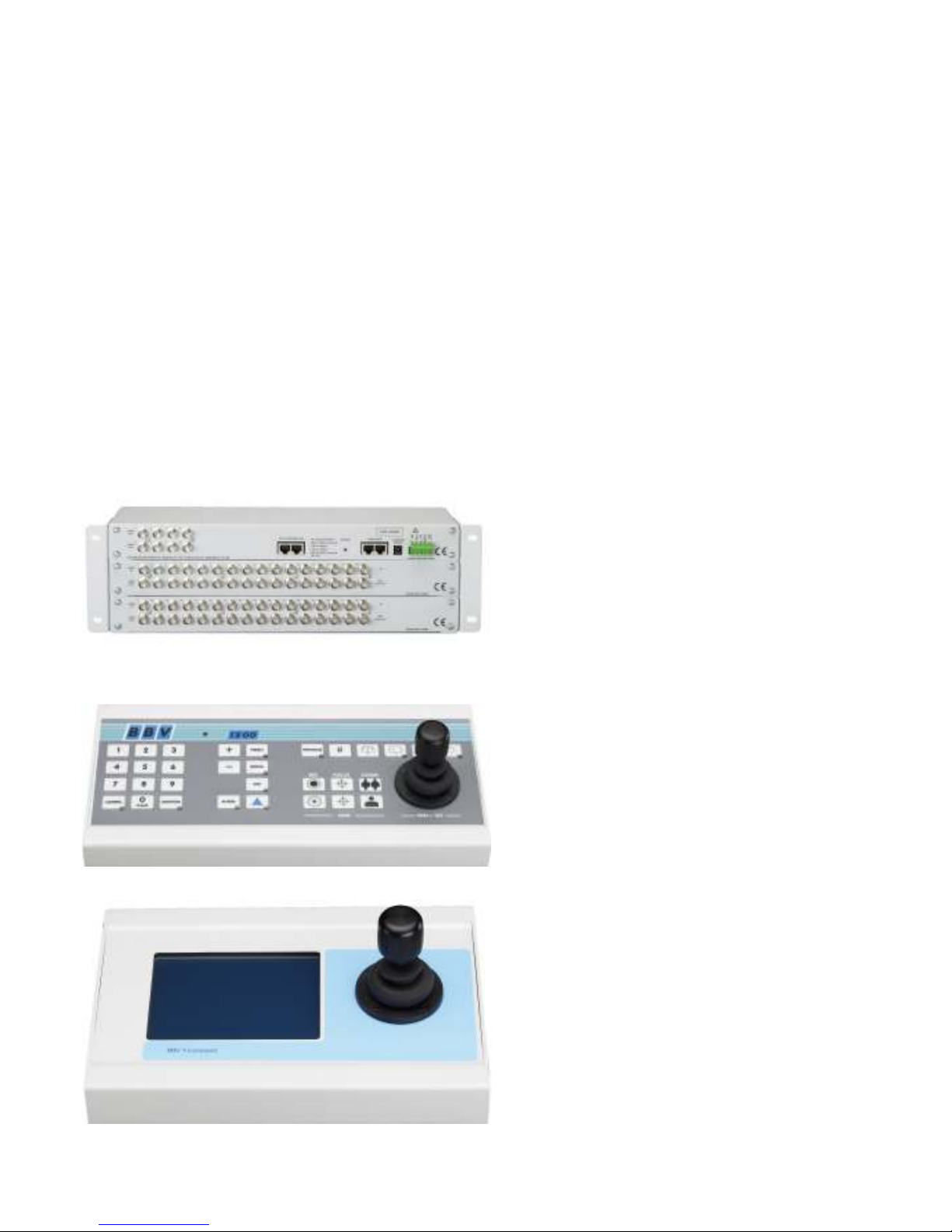
1 x TX1500 video matrix enclosed in a 19” sub rack.
1 x TX1500/KBD system Keypad or TCommand Touch Screen Keypad
3 x RJ45 straight patch cables
3 x RJ45 breakout boxes with self adhesive mounting pad
2 x 12Vdc1000mA power supply (1 for the matrix and 1 for the Keypad)
TX1500/32/8 matrix
Standard TX1500/KBD System Keypad
Optional T Command Touch Screen Keypad
Page 4

TX1500 Manual V4.1 Oct 2011.doc Page 4 of 32 TX1500 MATRIX
OVERVIEW
The TX1500 is a video matrix and telemetry control system offering control of up to 96 cameras from 4 control
positions. Eight monitor outputs are provided with monitors 1,2,3 & 4 having on screen display.
BBV & VISTA up-the-coax and BBV 422 & VISTA 485 linked receivers and domes can be controlled when
viewed on any monitor. Pelco and VCL up-the-coax control is limited to monitors 1-4.
Monitor outputs tested via CRT Monitors, recommended maximum cable (RG59) distance from matrix = 25 meters.
TFT Monitors may require additional amplification.
Site alarms and contacts are handled with alarm cards, each providing 16 inputs. Up to 6 alarm cards can be linked
into the TX1500 system either locally or remotely offering 96 alarm inputs
The TX1500/BBUS-IF interface, which appears as another Keypad, gives off-site control, via video/data transmission
equipment, and local control from PC and other equipment. The interface can be controlled using either the TX1000 or
TX1500 control protocol via either RS232 or RS422.
The TX1500 matrix communicates with all Keypads, alarm cards and BBUS-IF interfaces via a polled 4-wire multidrop
RS422 control bus named BBUS.
The matrix itself is in a subrack which can be fitted to a 19” rack using supplied fixing brackets. The fixing brackets
can be mounted on the front or rear face of the subrack. By fitting the ears on the back of the subrack, it can also be
wall mounted.
Alarm cards, BBUS-IF and StarCards are supplied in 1U sub racks as standard or can be fitted into the subrack with
the matrix if specified when ordering.
Larger subracks than standard can be supplied if specified when ordering.
PRODUCT CODES
TX1500/16/8 16 camera, 8 monitor matrix inc Keypad (supplied in 3U subrack)
TX1500/32/8 32 camera, 8 monitor matrix inc Keypad (supplied in 3U subrack)
TX1500/48/8 48 camera, 8 monitor matrix inc Keypad (supplied in 5U subrack)
TX1500/64/8 64 camera, 8 monitor matrix inc Keypad (supplied in 5U subrack)
TX1500/80/8 80 camera, 8 monitor matrix inc Keypad (supplied in 7U subrack)
TX1500/96/8 96 camera, 8 monitor matrix inc Keypad (supplied in 7U subrack)
TX1500/KBD Keypad with 3-axis joystick
TX1500/AL16 16 input alarm card, volts free normally closed inputs
TX1500/BBUS-IF BBUS Interface to allow control from a PC or other 3rd party equipment
STARCARD StarCard with 8 x RS422/485 outputs to allow star wired telemetry
STARCARD/CONVERTER As STARCARD with built in protocol conversion to allow control of domes etc.
EXPANDING AN EXISTING SYSTEM on site (maximum of 96 camera inputs)
The TX1500 can be expanded to a maximum of 96 cameras.
Larger subracks are inculed when required nesserary. All the cards from the existing subrack must be transferred to
the new subrack. Note down and put somewhere safe all the external connection information to aid re-commissioning
the system.
PRODUCT CODES
TX1500/EXP16/17-32/MK2 16 video input card to expand from a 16 camera to 32 camera system
TX1500/EXP16/33-48/MK2 16 video input card to expand from a 32 camera to 48 camera system
TX1500/EXP16/49-64/MK2 16 video input card to expand from a 48 camera to 64 camera system
TX1500/EXP16/65-80/MK2 16 video input card to expand from a 64 camera to 80 camera system
TX1500/EXP16/81-96/MK2 16 video input card to expand from a 80 camera to 96 camera system
3U TX1500/3U-SUBRACK
5U TX1500/5U-SUBRACK
7U TX1500/7U-SUBRACK
Page 5
TX1500 Manual V4.1 Oct 2011.doc Page 5 of 32 TX1500 MATRIX EXAMPLE
RX400P
AC P/T Zoom/Focus
Full Scene Presets
STATIC
static camera
RX55X
Multi protocol + DC
Preset pan/tilt camera
RX45X
Multi protocol + AC
Preset pan/tilt camera
RX35X
static camera with
lights/wash/wipe
RX300
static camera with
lights/wash/wipe
RX200
static camera with
lights/wash/wipe
RX10X
+ dome camera
RX100
+ dome camera
RX25X
static camera with
2 Auxiliaries
TX1500 ALARM CARD
TX1500/32/8 VIDEO MATRIX
STARCARD
9 -12 V ac or dc Supply
RJ45 Patch cable
RS422 BBUS Network
Video form Matrix to Monitor
Video form Cameras to Matrix
BBV422 telemetry control bus
Alarm circuit (normally closed)
TX1500/KBD (address 1)
TX1500/KBD (address 3) TX1500/KBD (address 4)TX1500/KBD (address 2)
PSU
PSU
PSU PSU
PSUPSUPSU
Page 6
TX1500 Manual V4.1 Oct 2011.doc Page 6 of 32 TX1500 MATRIX
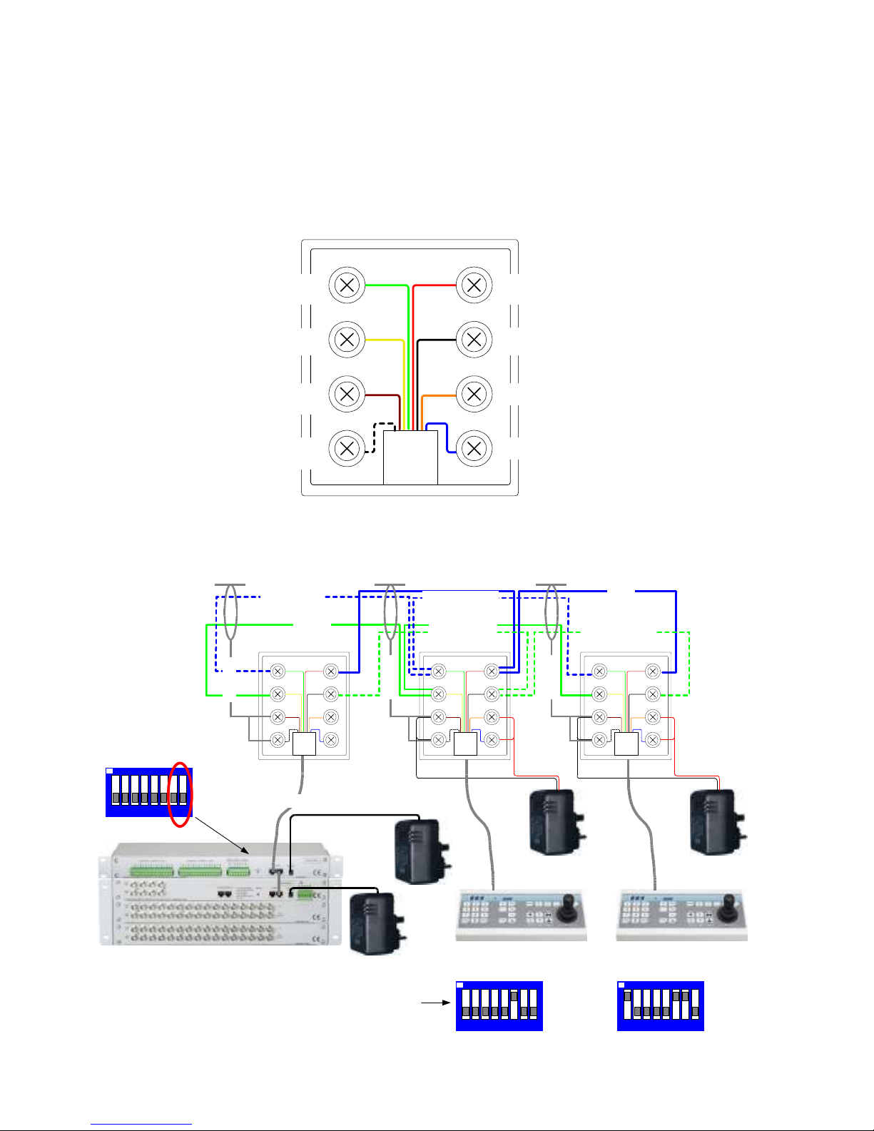
4 = TxA from MONITOR CARD (data +)TxB from MONITOR CARD (data -) = 5
(0v) GROUND= 7
DO NOT USED = 8
BLUE (CAT5)(CAT5) WHITE/BLUE
(CAT5) WHITE/BROWN
(CAT5) BROWN
GREEN RED
YELLOW BLACK
ORANGE
BLUEWHITE
BROWN
RxB to MONITOR CARD (data -) = 6
(CAT5) GREEN
3 = RxA to MONITOR CARD (data +)
WHITE/GREEN (CAT5)
2 = DO NOT USE (+V)
1 = DO NOT USE
BBUS CONTROL BUS
The TX1500 communicates with all Keypads, alarm cards and BBUS-IF interfaces via a polled 4 wire multidrop
RS422 control bus named BBUS.
All the units are equipped with standard RJ45 connectors allowing cat 5 patch cables to be used to connect over
short distances. On the larger sites RJ45 break out boxes are used to link between cat 5 cables and good quality
screen twin twisted pair data cable. Suitable types are the following Belden cables: 9842, 9829, 8162, 8132.
Fig 5. BBUS - RJ45 breakout box connector, MONITOR CARD end of BBus.
BBUS maximum distance 1200m end to end
GREEN RED
YELLOW BLACK
ORANGE
BLUEWHITE
BROWN
GREEN RED
YELLOW BLACK
ORANGE
BLUEWHITE
BROWN
GREEN RED
YELLOW BLACK
ORANGE
BLUEWHITE
BROWN
BLUE/WHITE
GREEN/WHITE
BLUE
GREEN
Tx Data (From matrix)
Rx Data (To matrix)
SCREEN
SCREEN
SCREEN
TX1500/AL16
Keypad 2
BBUS Terminated
1 - 5 = Keypad Address
6 = # & Program Enable
7 & 8 = BBUS termination
RJ45 patch cable max length = 2m
Alarm card
BBUS Un-Terminated
Switch 7-8 OFF
Keypad 1
BBUS Un-Terminated
TX1500/32/8
1 2 3 4 5 6 7 8
ON
1 2 3 4 5 6 7 8
ON
9-12Vdc
PSU
9-12Vdc
PSU
9-12Vdc
PSU
9-12Vdc
PSU
Card alarm 1 - 16
1 2 3 4 5 6 7 8
ON
Fig 6. Keypad BBUS wiring
Page 7
TX1500 Manual V4.1 Oct 2011.doc Page 7 of 32 TX1500 MATRIX
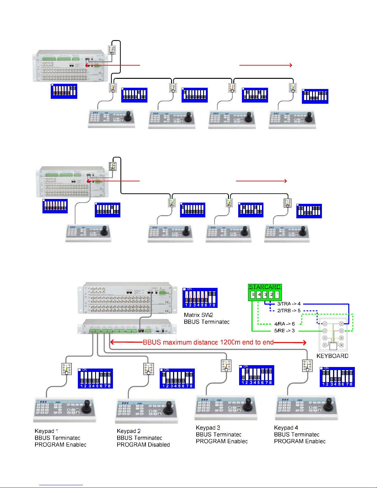
SYSTEM BBUS WIRING EXAMPLES
The following diagrams show examples of various wiring schemes.
Keypad 1
BBUS Un-Terminated
PROGRAM Enabled
1 2 3 4 5 6 7 8
ON
GREEN RED
YELLOW BLACK
ORANGE
BLUEWHITE
BROWN
GREEN RED
YELLOW BLACK
ORANGE
BLUEWHITE
BROWN
GREEN RED
YELLOW BLACK
ORANGE
BLUEWHITE
BROWN
GREEN RED
YELLOW BLACK
ORANGE
BLUEWHITE
BROWN
GREEN RED
YELLOW BLACK
ORANGE
BLUEWHITE
BROWN
BBUS maximum distance 1200m end to end
1 2 3 4 5 6 7 8
ON
1 2 3 4 5 6 7 8
ON
1 2 3 4 5 6 7 8
ON
1 2 3 4 5 6 7 8
ON
Keypad 2
BBUS Un-Terminated
PROGRAM Disabled
Keypad 3
BBUS Un-Terminated
PROGRAM Enabled
Keypad 4
BBUS Terminated
PROGRAM Enabled
Matrix SW2
BBUS Terminated
Fig 7. Example with all Keypads daisy chained from the TX1500 matrix using a single BBUS leg.
Keypad 1
BBUS Un-Terminated
PROGRAM Enabled
1 2 3 4 5 6 7 8
ON
GREEN RED
YELLOW BLACK
ORANGE
BLUEWHITE
BROWN
GREEN RED
YELLOW BLACK
ORANGE
BLUEWHITE
BROWN
GREEN RED
YELLOW BLACK
ORANGE
BLUEWHITE
BROWN
GREEN RED
YELLOW BLACK
ORANGE
BLUEWHITE
BROWN
BBUS maximum distance 1200m end to end
1 2 3 4 5 6 7 8
ON
1 2 3 4 5 6 7 8
ON
1 2 3 4 5 6 7 8
ON
1 2 3 4 5 6 7 8
ON
Keypad 2
BBUS Un-Terminated
PROGRAM Disabled
Keypad 3
BBUS Un-Terminated
PROGRAM Enabled
Keypad 4
BBUS Terminated
PROGRAM Enabled
Matrix SW2
BBUS Un-Terminated
Fig 8. Example with all Keypads daisy chained from the TX1500 matrix using two BBUS legs.
GREEN RED
YELLOW BLACK
ORANGE
BLUEWHITE
BROWN
GREEN RED
YELLOW BLACK
ORANGE
BLUEWHITE
BROWN
GREEN RED
YELLOW BLACK
ORANGE
BLUEWHITE
BROWN
GREEN RED
YELLOW BLACK
ORANGE
BLUEWHITE
BROWN
GREEN RED
YELLOW BLACK
ORANGE
BLUEWHITE
BROWN
Fig 9. Use of a starcard to allow star wiring of keypads.
Page 8
TX1500 Manual V4.1 Oct 2011.doc Page 8 of 32 TX1500 MATRIX
RS422 TELEMETRY OUT
DO NOT USED
DO NOT USED
DO NOT USED
4 = TxA to Telemerty Reciver RA(data +)TxB to Telemerty Reciver RB(data -) = 5
DO NOT USED
GROUND SCREEN = 7
GROUND SCREEN = 8
BLUE (CAT5)(CAT5) WHITE/BLUE
(CAT5) WHITE/BROWN
(CAT5) BROWN
GREEN RED
YELLOW BLACK
ORANGE
BLUEWHITE
BROWN
Fig 10. TELEMETRY – RJ45 breakout box connector.
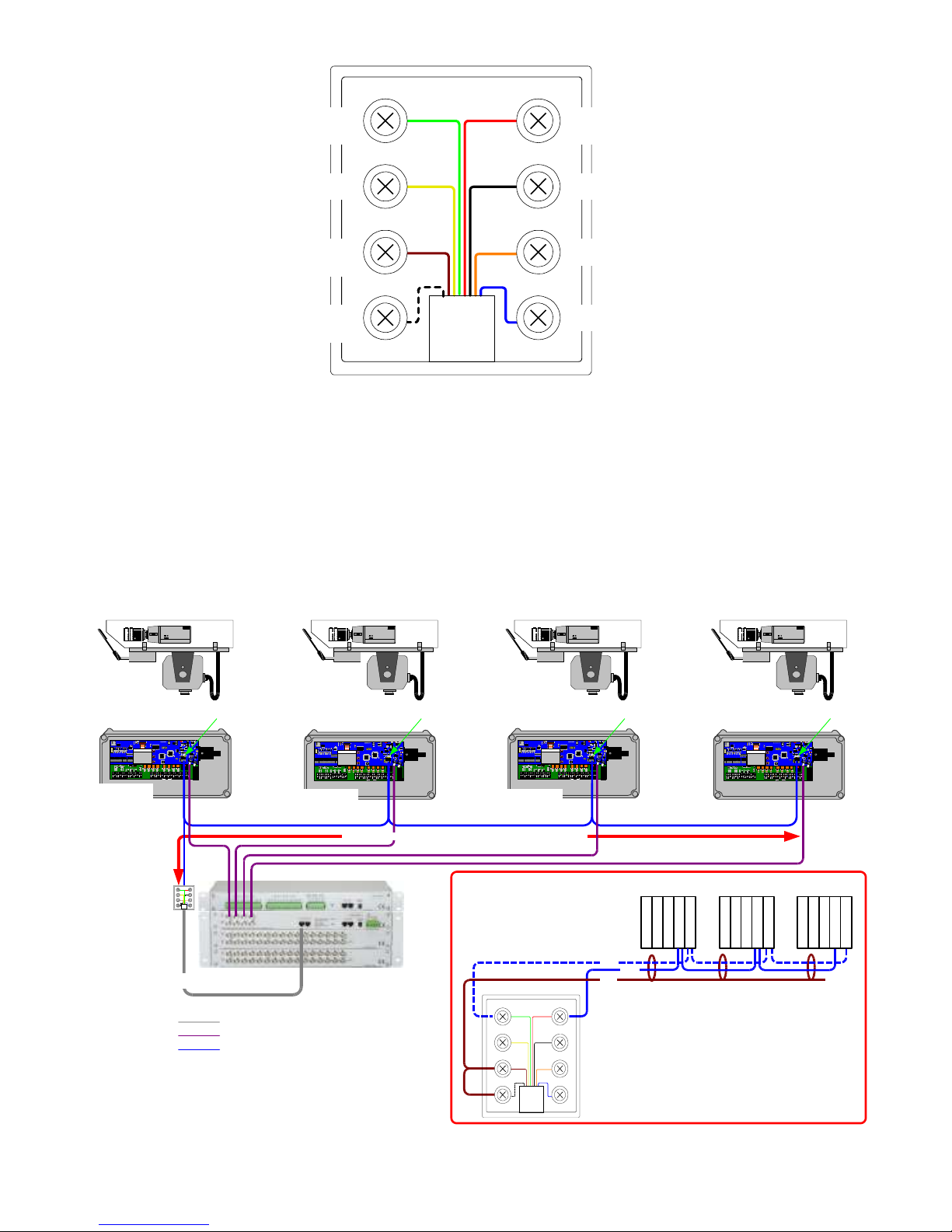
This port provides telemetry control via BBV RS422. Again a Cat 5 RJ45 patch cable and breakout box is used to
connect the telemetry receivers via single twisted pair cable. It is possible to either wire the network in a daisy
chained or star configuration using an optional BBV Starcard.
RS422 wiring configurations are shown below and on the following page.
RS422 TELEMETRY WIRING CONFIGURATIONS
Camera 1 Camera 2 Camera 3 Camera 4
o
230vPin1
Pin1
SupplyVoltageSW1
Setting
s230 Vor 115V
SW2
Set
tingsAU
X
OutputVol
tage
0 =Sup
plyVol
tageI =
24VAC
CameraLi
ghtsWip
e
W
as
h
N E L R U D
TRATRBGNDRARB
TRATRBGNDRARB
TELEM.
OUT TELEM.IN
Al
ar
ms
SW
3
SW
2
S
W1
UP
MEN
U
D
OW
N
L
CD1
BB
V
Ca
m
er
a
T
o
Mat
r
ix
OutOutGndA8GndA7GndA6GndA5GndA4GndA3GndA2GndA1
J2
o
2
30vPin1
Pin1
Supply
VoltageSW1
Settings
230 V
or 115V
SW
2
Setting
sAU
XOut
put
Voltage0 =
Sup
plyVoltage
I =
24VAC
Ca
meraLi
ghtsWipeWash
N E LR U D
TRATRB
GNDRARB
TRATRBGNDRA
RB
TEL
EM.
OUT TELEM.IN
A
l
arm
s
SW
3
S
W2
S
W1
U
P
M
EN
U
DO
W
N
LC
D1
BB
V
C
ame
r
a
T
oM
at
ri
x
OutOutGndA8GndA7GndA6GndA5GndA4GndA3GndA2Gnd
A1
J2
o
230vPin1
Pin1
SupplyVoltageSW1
Setting
s230 Vor 115V
SW2
Set
tingsAU
X
OutputVol
tage
0 =Sup
plyVol
tageI =
24VAC
CameraLi
ghtsWip
e
W
as
h
N E LR U D
TRATRBGNDRARB
TRATRBGNDRA
RB
TELEM.
OUT TELEM.IN
Al
ar
ms
SW
3
SW2
S
W1
UP
MEN
U
D
OW
N
L
CD1
BB
V
Ca
m
er
a
T
o
Mat
r
ix
OutOutGndA8GndA7GndA6GndA5GndA4GndA3GndA2GndA1
J2
o
2
30vPin1
Pin1
Supply
VoltageSW1
Settings
230 V
or 115V
SW
2
Setting
sAU
XOut
put
Voltage0 =
Sup
plyVoltage
I =
24VAC
Ca
meraLi
ghtsWipeWash
N E L R U D
TRATRBGNDRARB
TRATRBGNDRA
RB
TEL
EM.
OUT TELEM.IN
A
l
arm
s
S
W3
SW
2
SW1
U
P
M
EN
U
DO
W
N
LC
D1
BB
V
C
ame
r
a
T
oM
at
ri
x
OutOutGndA8GndA7GndA6GndA5GndA4GndA3GndA2GndA1
J2
Keep stub length as
short as possible
Keep stub length as
short as possible
Keep stub length as
short as possible
RX45X/55X Address 1
RX45X/55X Address 2 RX45X/55X Address 3 RX45X/55X Address 4
Un-Terminated Un-Terminated Un-Terminated Terminated
GREEN RED
YELLOW BLACK
ORANGE
BLUEWHITE
BROWN
RJ45 Breakout box
RJ45 Patch cable
RJ45 Patch cable
Video form Cameras to Matrix
BBV422 telemetry control bus
RX45x/55X J2 TELEMETRY IN
Screen (optional) connect at matrix only
1
T
R
A
2
T
R
B
3
G
N
D
4
R
A
5
R
B
1
T
R
A
2
T
R
B
3
G
N
D
4
R
A
5
R
B
1
T
R
A
2
T
R
B
3
G
N
D
4
R
A
5
R
B
TB/-
TA/+
Gnd
GREEN RED
YELLOW BLACK
ORANGE
BLUEWHITE
BROWN
DETAILED VIEW
Maximum distance 1200m end to end
Fig 11. Daisy Chained RS422 Telemetry Wiring
Page 9
TX1500 Manual V4.1 Oct 2011.doc Page 9 of 32 TX1500 MATRIX
o
2
30vPin1
Pin1
SupplyVoltage
SW1Setting
s
230 Vor 115V
SW
2Set
tings
AUX
Out
putVoltage
0 =Sup
plyVol
tageI =
24V
AC
CameraLi
ghtsWip
e
W
as
h
N E L R U D
TRATRBGNDRARB
TRATRB
GNDRARB
TEL
EM.OUT TELEM.IN
A
lar
m
s
S
W3
SW2
SW
1
UP
ME
N
U
DO
W
N
L
CD1
BBV
Cam
e
ra
To
Ma
tr
i
x
OutOutGndA8GndA7GndA6GndA5GndA4GndA3GndA2Gnd
A1
J
2
RX45X/55X Address 4
Terminated
o
230vPin1
Pin1
Supply
VoltageSW1Setting
s
230 Vor 115V
SW
2Set
ting
sAUX
Out
putVoltage
0 =Sup
ply
VoltageI =
24V
AC
CameraLi
gh
ts
Wi
p
e
W
a
sh
N E LRU D
TRATRBGNDRA
RB
TRATRBGNDRAR
B
TEL
EM.OUT TELEM.
IN
A
la
rm
s
SW
3
SW2
S
W1
UP
M
EN
U
DO
W
N
L
CD1
BBV
Cam
e
ra
To
M
atr
i
x
OutOutGndA8GndA7GndA6GndA5GndA4GndA3GndA2Gnd
A1
J2
RX45X/55X Address 3
Terminated
o
2
30vPin1
Pin1
SupplyVoltage
SW1Setting
s
230 Vor 115V
SW
2Set
tings
AUX
Out
putVoltage
0 =Sup
plyVol
tageI =
24V
AC
CameraLi
ghtsWip
e
W
as
h
N E L R U D
TRATRBGNDRA
RB
TRATRBGNDRARB
TEL
EM.OUT TELEM.IN
A
lar
m
s
SW
3
SW2
S
W1
UP
ME
N
U
DO
W
N
L
CD1
BBV
Cam
e
ra
To
Ma
tr
i
x
OutOutGndA8GndA7GndA6GndA5GndA4GndA3GndA2GndA1
J
2
RX45X/55X Address 2
o
230vPin1
Pin1
Supply
VoltageSW1Setting
s
230 Vor 115V
SW
2Set
ting
sAUX
Out
putVoltage
0 =Sup
ply
VoltageI =
24V
AC
CameraLi
gh
ts
Wi
p
e
W
a
sh
N E L R U D
TRA
TRB
GNDRARB
TRATRBGNDRARB
TEL
EM.OUT TELEM.
IN
A
la
rm
s
SW3
S
W2
SW
1
UP
M
EN
U
DO
W
N
L
CD1
BBV
Cam
e
ra
To
M
atr
i
x
OutOutGndA8GndA7GndA6GndA5GndA4GndA3GndA2GndA
1
J2
RX45X/55X Address 1
Terminated
Camera 1 Camera 2 Camera 3 Camera 4
Terminated
RJ45 Patch cable
Video form Cameras to Matrix
BBV422 telemetry control bus
Maximum distance 1200m end to end
DETAILED VIEW
Maximum distance 1200m
end to end
1 2 3 4 5 6 7 8
ON
Starcard SW3 must be
set to 4 wire as shown.
STAR PORT
OF
STARCARD
RX45X/55X J2
NCNCTRA DATA A/+
TRB DATA B/-
GND
NCNCGNDRARB
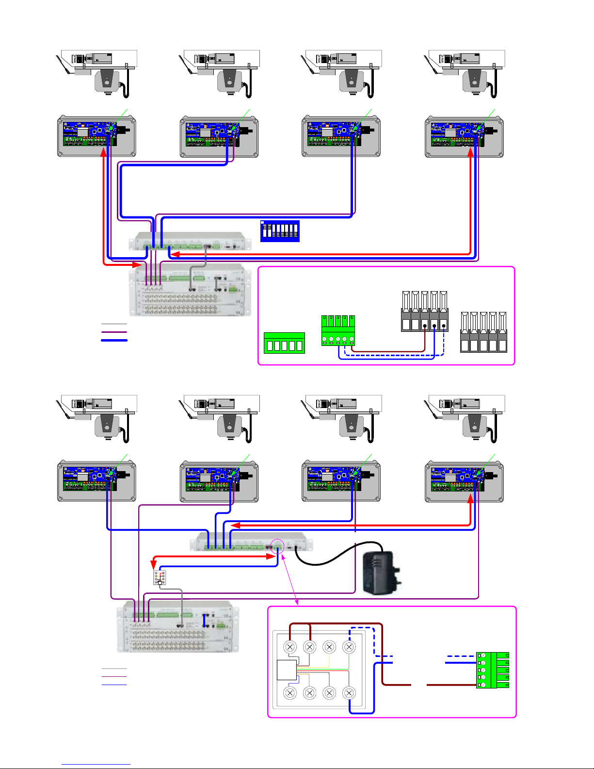
Fig 12. Star Wired Configuration using the optional BBV starcard
Camera 1 Camera 2 Camera 3 Camera 4
o
2
30vPin1
Pin1
SupplyVoltageSW1
Settings
230 Vor 115V
SW
2
Settings
AU
XOut
putVoltage
0 =
SupplyVol
tage
I =24V
AC
Ca
meraLightsWipeWas
h
N E L R U D
TRATRBGNDRARB
TRATRB
GNDRARB
TEL
EM.
OUT TELEM.IN
A
l
arm
s
S
W3
SW2
SW
1
U
P
MEN
U
D
OW
N
L
CD
1
BB
V
Ca
me
ra
T
oMa
t
ri
x
OutOutGndA8GndA7GndA6GndA5GndA4GndA3GndA2Gnd
A1
J2
o
2
30vPin1
Pin1
SupplyVoltageSW1
Settings
230 V
or 115V
SW
2
Setting
sAU
XOut
putVoltage
0 =
Supply
Voltage
I =24V
AC
Ca
meraLightsWipeWa
sh
N E LRU D
TRATRBGNDRA
RB
TRATRBGNDRAR
B
TEL
EM.
OUT TELEM.IN
A
l
arm
s
SW
3
SW2
S
W1
U
P
MEN
U
DOW
N
L
C
D1
BB
V
C
ame
r
a
T
oM
at
ri
x
OutOutGndA8GndA7GndA6GndA5GndA4GndA3GndA2Gnd
A1
J2
o
2
30vPin1
Pin1
SupplyVoltageSW1
Settings
230 Vor 115V
SW
2
Settings
AU
XOut
putVoltage
0 =
SupplyVol
tage
I =24V
AC
Ca
meraLightsWipeWas
h
N E L R U D
TRATRBGNDRA
RB
TRATRBGNDRARB
TEL
EM.
OUT TELEM.IN
A
l
arm
s
SW
3
SW2
S
W1
U
P
MEN
U
D
OW
N
L
CD
1
BB
V
Ca
me
ra
T
oMa
t
ri
x
OutOutGndA8GndA7GndA6GndA5GndA4GndA3GndA2GndA1
J2
o
2
30vPin1
Pin1
SupplyVoltageSW1
Settings
230 V
or 115V
SW
2
Setting
sAU
XOut
putVoltage
0 =
Supply
Voltage
I =24V
AC
Ca
meraLightsWipeWa
sh
N E L R U D
TRA
TRB
GNDRARB
TRATRBGNDRARB
TEL
EM.
OUT TELEM.IN
A
l
arm
s
SW3
S
W2
SW
1
U
P
MEN
U
DOW
N
L
C
D1
BB
V
C
ame
r
a
T
oM
at
ri
x
OutOutGndA8GndA7GndA6GndA5GndA4GndA3GndA2GndA
1
J2
RX45X/55X Address 1
RX45X/55X Address 2 RX45X/55X Address 3 RX45X/55X Address 4
Terminated Terminated Terminated Terminated
GREEN RED
YELLOW BLACK
ORANGE
BLUEWHITE
BROWN
RJ45 Patch cable
Video form Cameras to Matrix
BBV422 telemetry control bus
Maximum distance 1200m end to end
MASTER
PORT
RJ45 Breakout box
DETAILED VIEW
From TX1500 TB (PIN5)
From TX1500 TA (PIN4)
Screen
GREEN RED
YELLOW BLACK
ORANGE
BLUEWHITE
BROWN
Fig 13. Use of starcard mounted remotely, reducing cable runs
Page 10
TX1500 Manual V4.1 Oct 2011.doc Page 10 of 32 TX1500 MATRIX
VIDEO INPUT CARD
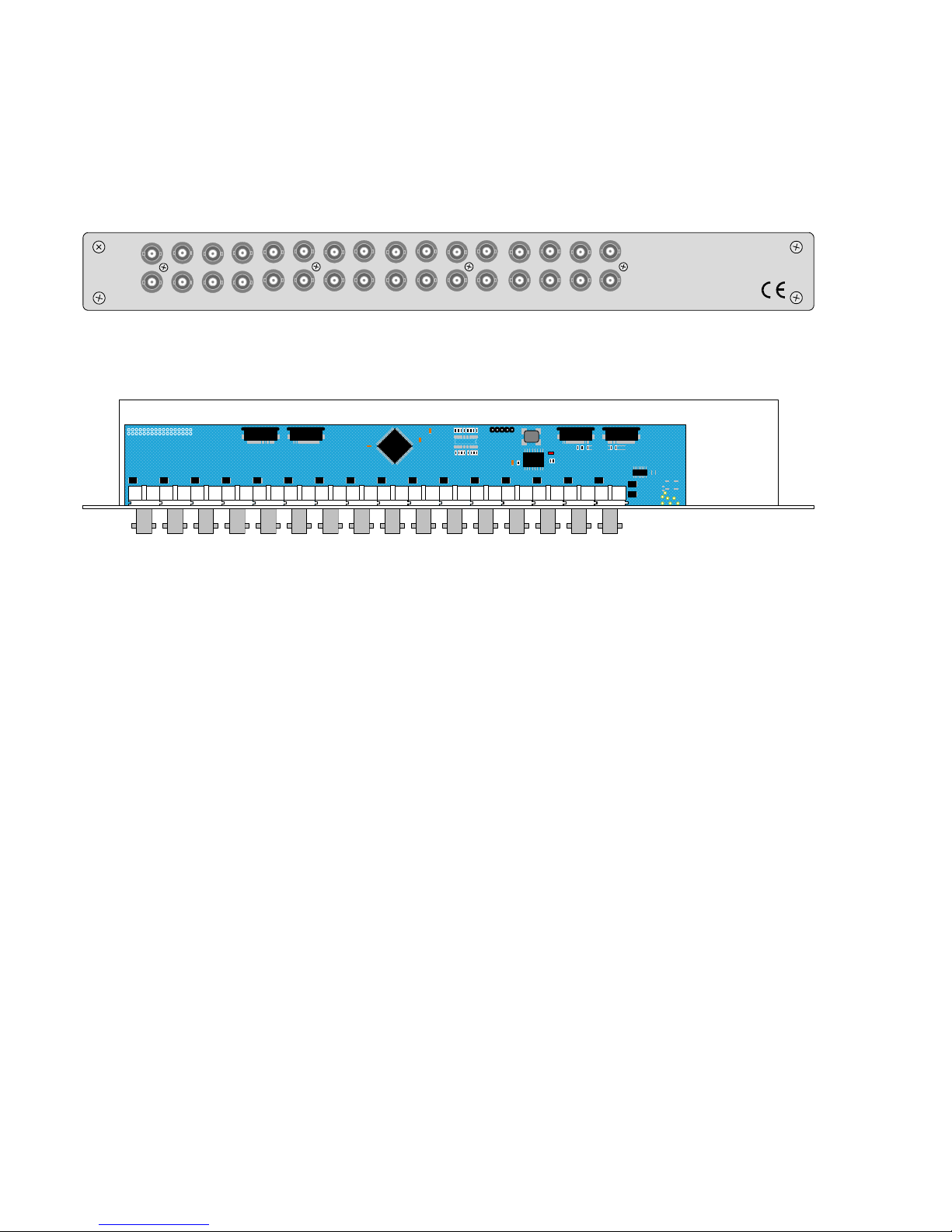
The Video Input Card is used to connect 16 camera inputs to the TX1500. Systems larger than
16 cameras will use multiple cards. The input cards are self addressing.
Each input has a corresponding looping output on the lower BNC connector. The camera inputs
are passively terminated at 75Ω and auto de-terminate when a BNC plug is connected to the
looping output. Up to 6 cards can be connected in a matrix to control up to 96 cameras.
IN
VIDEO INPUT CARD
1 2 3 4
5 6 7 8
VIDEO
IN
VIDEO
OUT
OUT
Auto Hi-Z
9 10 11 12 13 14 15 16
Video Input card Front Panel View
Video bus
Control bus
PL1
PL5
BBV
The address of each input card is dicated by its location that with in the matrix. In earlier matrixes
there were dipswitches used these are refure to MK1 input cards and are not compatible with
this type of input card a MK2.
Page 11
TX1500 Manual V4.1 Oct 2011.doc Page 11 of 32 TX1500 MATRIX
MONITOR OUTPUT CARD
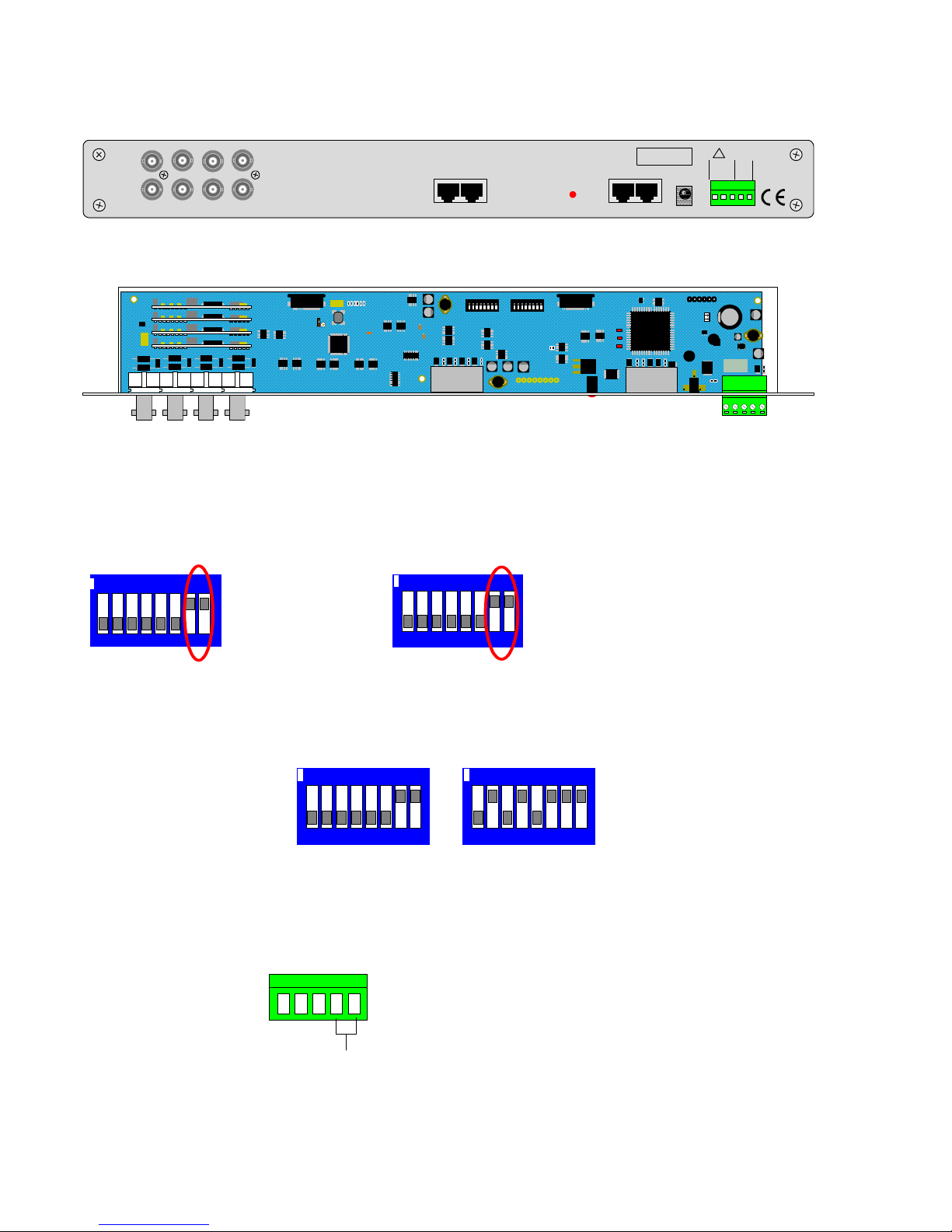
This card provides the 8 monitor outputs, BBUS, RS422 telemetry and a relay output.
Internal switches are used during specific BBV tests that should not require on site adjustment.
SERIAL NUMBER
BBUS PORT
STATUS1 & 2 +DC Out 100mA
3 RX- A Refer to manual
4 TR- A Output
5 TR- B Output
6 RX- B Refer to manual
7 & 8 0V
RS 422 CONTROL OUT
TX1500 MONITOR CARDBUILDING BLOCK VIDEO LTD MADE IN U.K. TEL +44 (0) 1323 842727 WWW.BBVCCTV.COM
1 2 3 4
5 6 7 8
VIDEO
OUT
VIDEO
OUT
12V AC/DC
(1000mA)
NO
COMNCGND
ALM 0
1 2 3 4 5
Monitor Output card Front Panel View
Monitor outputs tested via CRT Monitors, recommended maximum cable (RG59) distance from matrix = 25 meters. TFT Monitors
may require additional amplification.
PL2
BBV
PL6
RS422
OUT
B-BUS
ON
1 2 3 4 5 6 7 8ON1 2 3 4 5 6 7 8
ON
1 2 3 4
PL1
01002 iss 5
Monitor Output card internal view
LD1 STATUS – Front Panel indication of system and BBUS operation. Refer to page 16.
Internal LEDs,
LD2 – BBV debug use.
For normal operation the internal switches must be as shown below:
To reset system to factory defaults:-
Power off the TX1500, set the switches as below and power up the
TX1500. On screen instructions are displayed on monitor 1 output.
NOTE: The Power Up Factory Reset option will delete all TX1500 parameter programming.
Contact BBV technical support for guidance. +44(0)1323 444600.
NO
NC
COM
ALARM 00
1 2 3 4 5
Alarm 00 input can
trigger one of several
actions, refer to page 19
Input from v olts free,
normally closed contacts
CHANGEOVE R RE LA Y
operated by the triangle
key
Volts free contacts for low
voltage switch ing only
1 2 3 4 5 6 7 8
ON
Power Up Factory Reset
1 2 3 4 5 6 7 8
ON
SW1 SW2
1 2 3 4 5 6 7 8
ON
1 2 3 4 5 6 7 8
ON
SW 1 SW 2
B-B U S RS48 5
ON = T e rmin ated
OFF = U n -term inated
RS485 T e lem etry
ON = T e rmin ated
OFF = U n -term inated
Page 12
TX1500 Manual V4.1 Oct 2011.doc Page 12 of 32 TX1500 MATRIX
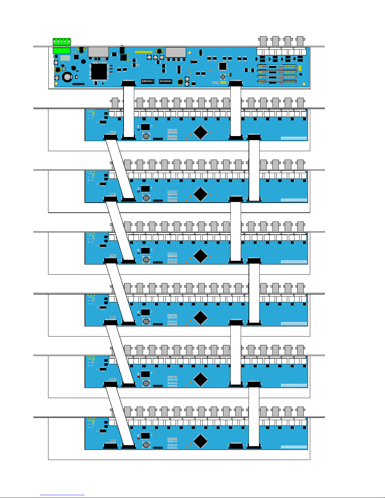
96 CAMERA SYSTEM SUBRACK CARD CONFIGURATION
Monitor Output Card
PL2
BBV
PL6
O
N
1 2 3 4 5 6 7 8
O
N
1 2 3 4 5 6 7 8
O
N
1 2 3 4
PL1
01002 iss 5
Video bus
Control bus
PL1
PL5
BBV
R
I
B
B
O
N
Video bus
Control bus
PL1
PL5
BBV
Video bus
Control bus
PL1
PL5
BBV
Video bus
Control bus
PL1
PL5
BBV
Video bus
Control bus
PL1
PL5
BBV
Video bus
Control bus
PL1
PL5
BBV
R
I
B
B
O
N
R
I
B
B
O
N
R
I
B
B
O
N
R
I
B
B
O
N
R
I
B
B
O
N
R
I
B
B
O
N
R
I
B
B
O
N
R
I
B
B
O
N
R
I
B
B
O
N
R
I
B
B
O
N
R
I
B
B
O
N
Camera 1 - 16
Camera 17 - 32
Camera 33 - 48
Camera 65 - 80
Camera 81 - 96
Video Input Card
Video Input Card
Video Input Card
Video Input Card
Video Input Card
Video Input Card
Camera 49 - 64
Wiring for Video Input cards and Monitor Output card.
Page 13

TX1500 Manual V4.1 Oct 2011.doc Page 13 of 32 TX1500 MATRIX
MATRIX DIAGNOSTICS
The matrix STATUS led indicates system operation as follows:
Flashing Dimly The matrix is powered with at least one Keypad connected. Use 58# to display the
Keypad numbers that the matrix has detected on the BBUS.
Mainly OFF, 1 second ON The matrix is powered with no Keypads connected. – If Keypads are connected then
make sure that each Keypad address is unique between 0 – 3. Keypads sharing an
address will cause the matrix to ignore both Keypads with unpredictable results.
OFF The matrix is powered with no Keypads connected or the matrix is not powered or
has an internal fault. If the power supply seems fine then please contact technical
support for further assistance.
Several commands exist that allow on site diagnostics. These commands must be entered from Keypad 1 and
display results on monitor output 1.
51# Display the matrix firmware version, number of resets and watchdog resets.
TX1500 Version shows the matrix firmware version number ie 2.3
resets shows the number of times that the system has lost power or the menu has been accessed.
watchdogs shows the number of times the matrix watchdog has reset the matrix. A high figure here can
indicate that there may be interference or power fluctuations.
55# Coaxial telemetry on.
With normal operation, the coaxial telemetry is only transmitted to a receiver whilst a camera is being
controlled. After a short period the telemetry transmission is stopped. This is prevent interference to sync
separators in DVRs etc. W hen trouble shooting telemetry problems the telemetry should be on all the time
so the 55# command would be used and then the receiver CABLE and ERROR leds inspected. Pressing #
again will stop the telemetry transmission.
56# Display the status of matrix switch SW1, the display shows a HEX number which corresponds to the switch
settings for SW1. The number is displayed whilst the # key is pressed. Releasing the # key will clear the
number from the screen.
Number displayed SW1 switch
0 1 - 6 OFF
1 1 ON
2 2 ON
4 3 ON
8 4 ON
10 5 ON
20 6 ON
When more than 1 switch is ON then the number displayed will the sum of the values of all switches that are
ON, ie. 1,2 ON, display shows 03, 1,2,3,4 ON displays 0F
RS422 telemetry directly from the TELEMETRY port and should not normally be selected.
Example numbers that could be displayed
0 = normal mode
1 = DIXONS mode – This is a special mode developed for DSG driving Mark Mercer
57# Display the status of matrix switch SW2 as per 56#.
2A = SW2-2/4/6 ON = FACTORY INITIALISATION on a power up. This is used to clear any programming
and load default values. Useful if the matrix has had a corrupted programming. Once powered up turn all
SW2 switches OFF again to prevent further accidental initialisations.
58# Display number of Keypads or BBUS/I-F with addresses connected to the matrix along with the software
version of each Keypad or BBUS/I-F.
Page 14
TX1500 Manual V4.1 Oct 2011.doc Page 14 of 32 TX1500/AL16 16 INPUT ALARM CARD
TX1500/AL16 - 16 ALARM INPUT CARD
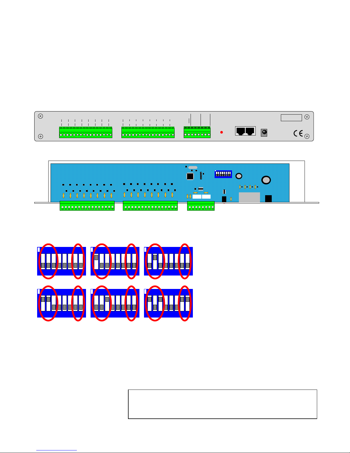
Each alarm card provides 16 individual normally closed volts free alarm inputs. The card communicates via the BBUS
with the monitor output card. Power is supplied either via the BBUS interface when the alarm card is mounted in the
TX1500 subrack or via an external 9Vdc supply when mounted remotely.
NOTE: Only 1 alarm card can be powered from the BBUS port.
The power led is used as a status indication and shows the following:
Mainly ON, flashing OFF when the alarm card is polled, approx 2-3 times every second. (NORMAL)
OFF permanently – alarm card not powered or faulty.
ON permanently – Not polled by MONITOR card, BBUS cable faulty or ALARM card faulty.
SERIAL NUMBER
BBUS PORT
STATUS
ALARM CARD
BUILDING BLOCK VIDEO LTD MADE IN U.K. TEL +44 (0) 1323 842727 WWW.BBVCCTV.COM
12V AC/DC
(500mA)
6
NO
COM
NC
7 83
NO
COM
NC
4 5
GND
1 2
LINK TO
DISABLE
RELAY
OUTPUT 2
RELAY
OUTPUT 1
GND
1
GND2GND3GND4GND5GND6GND7GND
8
GND9GND
10
GND11GND12GND13GND14GND15GND
16
ALARM INPUTS NORMALLY CLOSED ALARM INPUTS NORMALLY CLOSED
Fig 23. Alarm card front panel view
1 2 3 4 5 6 7 8
ON
Fig 24. Alarm card internal view
Fig 25. Alarm card SW1 address switch settings
Each alarm card has two single pole changeover relays called Relay 1 and Relay 2. These relays can be driven manually
and also from alarm activations. The system relay numbers are assigned as follows:
Alarm Card Relay 1 Relay 2
1 1 2
2 3 4
3 5 6
4 7 8
5 9 10
6 11 12
1 2 3 4 5 6 7 8
ON
SW1 is used to set the alarm card address as follows:
1 2 3 4 5 6 7 8
ON
1 2 3 4 5 6 7 8
ON
1 2 3 4 5 6 7 8
ON
1 2 3 4 5 6 7 8
ON
1 2 3 4 5 6 7 8
ON
Card 1 alarm 1-16 Card 2 alarm 17-32 Card 3 alarm 33-48
Card 4 alarm 49-64 Card 5 alarm 65-80 Card 6 alarm 81-96
Switches 7 & 8
BBUS RS485 Termination
ON = Terminated
OFF = Un-terminated
Must be ON if the alarm card is at
the end of line and OFF otherwise.
Alarm card 6 shown as end of line.
Note: alarm card relay 1 cannot be controlled from the keyboards as it is an
alarm output contact that changes state when any alarm becomes active.
This allows it to be used to switch a VCR into realtime recording etc. The
duration is set in the matrix menu. – Relay 1 Time
Page 15
TX1500 Manual V4.1 Oct 2011.doc Page 15 of 32 MATRIX PROGRAMMING/USER GUIDE
Enter Pin Number
* * * * * *
+ or - = Enter Key
Joystick to Navigate
Press Program to exit
Exit
CONFIGURATION USING THE TX1500 MENUS
NOTE only Keypad 1 can access the TX1500 system menu and only monitor 1 can display the menu.
Out of the box the TX1500 is configured to control BBV coaxial telemetry on all cameras and all Keypads can control all
the monitors and cameras.
The TX1500 menu system allows the unit to be configured to your customer’s site requirements.
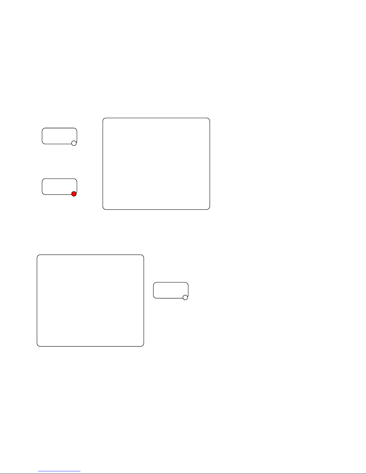
To access the menu select monitor 1 by pressing ‘1’ ‘MON’ and use Keypad 1. Press and hold the ‘PROGRAM’ key for
2-3 seconds and the following screen will be displayed and the ‘PROGRAM’ led is lit. If the menu is not displayed then
check that the program key is enabled on the Keypad by turning switch 6 ON.
Press for 2 seconds
The menu is displayed Enter the six digit PIN using
and the PROGRAM led keys 0 – 9.
is lit.
The default PIN is 999999
Use the joystick left and right if a digit is entered incorrectly.
The TX1500 Main Menu is displayed if the PIN is correct otherwise the TX1500 reverts to normal control.
To navigate through the menu, use the joystick and either the +/- keys to
toggle a value or the numeric keys 0-9 if a value is required.
To exit the menu press the PROGRAM key at any point.
Each menu item is described on the following pages
PROGRAM
PROGRAM
TX1500 - Main Menu
System Basics
Access Tables
Alarm Menus
Sequences
Camera Types
Set Passwords
System Parameters
Exit press + to select
PROGRAM
Page 16

TX1500 Manual V4.1 Oct 2011.doc Page 16 of 32 MATRIX PROGRAMMING/USER GUIDE
SYSTEM BASICS
This example screen shows the settings for a site with 10
cameras, 2 Keypads and a single alarm card with 16 alarm inputs.
Maximum Camera number:
Specifies how many video inputs are connected to the matrix and
prevents switching to non-existent cameras. Valid values are 01 96
Maximum Alarm number:
Specifies how many alarm inputs are connected to the matrix. Set as below:-
Alarm cards
Maximum
Alarm number
0 0
1 16
2 32
3 48
4 64
5 80
6 96
Text on Monitors:
Monitor outputs 1 – 4 display the camera number, monitor number and other messages. Text on these monitors can be
disabled by using the + or – key to cycle through options.
Display Line:
The TX1500 status line can be moved up or down on the screen to prevent the TX1500 text from being overwritten by
the text from other components of the system. Use +/- to cycle through values.
0 being the top of the screen and 10 the bottom of the screen.
System Type:
Sets the CCTV video standard as PAL or NTSC. Use the +/- keys to select the standard. Normally PAL in the UK.
Number of Keypads:
Sets the number of Keypads connected to the matrix
Return:
Returns to the TX1500 Main Menu.
System Basics
Maximum Camera number 10
Maximum Alarm number 16
Text on Monitors 1+2+3+4
Display Line 9
System Type PAL
Number of Keyboards 2
Return
Page 17

TX1500 Manual V4.1 Oct 2011.doc Page 17 of 32 MATRIX PROGRAMMING/USER GUIDE
ACCESS TABLES
One of the advanced features of the TX1500 system is the ability to prevent specific cameras from being displayed on
specific monitors and to prevent specific Keypads from moving cameras.
The Access Table screen is used to program which monitors each Keypad can control. A setting of ‘Y’ is used if the
Keypad is allowed to control a monitor and ‘N’ to prevent control.
This screen shows the settings for a site with two Keypads. Each Keypad
has it’s own monitor and is locked out of controlling the other Keypad’s
monitor.
i.e.
Keypad 1 can control monitor 1 ONLY
Keypad 2 can control monitor 2 ONLY
Pressing the +/- keys will toggle the value of each monitor between Y and
N.
NB: Keypad 1 can always control monitor 1 as this is used to setup the
matrix.
On power up the matrix interrogates devices on the BBUS and all control devices are displayed on this screen.
Recognised control devices are:-.
Displayed Description
TX 1500 Standard TX1500 joystick Keypad
TCommand Touch Screen Keypad
232 I/F BBUS Interface allowing control from PC and from remote sites etc.
Allocating cameras to monitors and Keypads is programmed from the Camera Types screen.
Access Table
Keyboard to Monitors
1 2 3 4 5 6 7 8
1 Tx 1500 v6 Y N N N N N N N
2 Tx 1500 v6 N Y N N N N N N
3 Not Fitted N N N N N N N N
4 Not Fitted N N N N N N N N
Return
Page 18

TX1500 Manual V4.1 Oct 2011.doc Page 18 of 32 MATRIX PROGRAMMING/USER GUIDE
ALARM MENUS
Alarm handling of the TX1500 is programmed from the Alarm Menu screens.
Up to four actions can be carried out following each alarm activation. Eg four cameras could move to preset positions to
triangulate onto an event.
On selection of Alarm Menus the following screen is displayed
This example shows a system with a single 16 input alarm card.
The TX1500 will display the total number of alarms that can be
programmed based on the Maximum Alarm number set in the System
Basics menu.
Input Action:
Sets the action for the ALARM 00 input on the matrix monitor board. Use +/- to cycle through the options.
No Action – ALARM 00 is not used.
Disable Alm – is used to disable all alarms when ALARM 00 is shorted to GND.
Alarm 00 – ALARM 00 is used as an alarm input in addition to the TX1500/AL16 alarm card inputs.
NOTE: Always handled in ‘AUTOMATIC’ mode, regardless of ‘Alarm stack’ setting.
Alarm Beep Time:
Number of seconds that all the Keypads ‘beep’ following an alarm input. Use +/- to cycle through the values.
0, 4, 6, 8, 10, 15, 20 Seconds
Alarm Stack:
The matrix alarm handling can be automatic, ie the system will drive cameras to presets as alarms occur or require an
operator input before the alarm is actioned. Use the +/- to toggle between Automatic and Manual.
Automatic – Alarm activations are handled automatically
Manual – The ALARM key must be pressed to acknowledge an alarm activation
Relay 1 Time:
The number of seconds that the Relay 1 output of alarm card 1 is active following any alarm.
Use +/- to cycle through the various time delays. 10, 30, 60, 90, 120, 150, 200 or 250 seconds.
Enter the 2 digit alarm number you wish to program using the 0-9 keys. Eg enter 01 for alarm 1. The following screen
will then be displayed. See the relay number mentioned on page 17.
Each of the four actions can allow a camera to be moved to a preset
position and displayed on a monitor output. In addition, if the monitor was
sequencing before the alarm occurred, after ‘time’ seconds the sequence
is re-started.
If alarms are taken into the local alarm input of a telemetry receiver that
supports local alarms, ie Rx100/Rx400DC/Rx45X/Rx55X, ‘pre’ must be
set to 00 as the preset will depend on the receiver alarm input. (See the
receiver manual for more details on local alarms.)
This simple example shows alarm 1 moving camera 1 to preset 1 and
display on monitor 1.
next and prev allow setting the alarm actions for the next and previous
alarm inputs.
You have 16 alarms
enabled and connected
Edit Alarm number 00
Input Action Disable Alm
Alarm Beep Time 6 Seconds
Alarm Stack Automatic
Relay 1 Time 60 Seconds
Return
Alarm 1
kbd cam mon pre time
Act 1 01 1 01 30s
No Act 1 01 1 00 30s
No Act 1 01 1 00 30s
No Act 1 01 1 00 30s
Return Exit next prev
Page 19

TX1500 Manual V4.1 Oct 2011.doc Page 19 of 32 MATRIX PROGRAMMING/USER GUIDE
SEQUENCES
Each of the 8 monitor outputs of the TX1500 can sequence between all or specific cameras. Each camera can be
individually added or removed from each monitor sequence. For example, in a retail environment public store monitors
are prevented from displaying sensitive areas of the store whilst monitors in the security office can sequence all
cameras.
If a camera greater than the Maximum Camera Number is added to a
sequence this camera will be ignored when the sequence is running.
Selecting Cameras 01 – 08 will display the following screen
Monitors 1 to 8 are shown with monitor 1 the top line and monitor 8 the
bottom line.
The first item is the type of sequence or the dwell time if running a
standard sequence. The screen on the left shows all the variants of
sequences and dwell times.
Sequence types:
2/5/15… Second – standard sequence with a dwell time before displaying the next camera.
Random – The cameras are sequenced as above from lowest to highest but with a random dwell
time between each camera.
Full Rand – In Full Random the monitor will display a completely random camera for a random
period of time. This is useful for public display monitors on shop floor to prevent
shoplifters remembering the displayed sequence.
A camera will be in a specific monitor’s sequence if a Y is displayed or be skipped if an N is displayed.
Use the + or – keys to toggle between Y and N.
Next8 displays the next bank of 8 cameras.
Sequence Setup Selection
Cameras 01 - 08
Cameras 09 - 16
Cameras 17 - 24
Cameras 25 - 32
Cameras 33 - 40
Cameras 41 - 48
Cameras 49 - 56
Cameras 57 - 96
Return
monitor sequence setup
cam 1234 5678
1 2 Second YYYY YYYY
2 5 Second YYYY YYYY
3 15 Second YYYY YYYY
4 20 Second YYYY YYYY
5 25 Second YYYY YYYY
6 30 Second YYYY YYYY
7 Full Rand YYYY YYYY
8 Random YYYY YYYY
Return Menu Next8
Page 20

TX1500 Manual V4.1 Oct 2011.doc Page 20 of 32 MATRIX PROGRAMMING/USER GUIDE
CAMERA TYPES
These screens are used to set the type of telemetry for each camera and which monitors and Keypads are allowed to
view and control each camera.
The cameras are again displayed in banks of 8 as shown on the following
screen:
Start at Cameras 01 – 08 to display the setup screen
This example shows Camera 1,2,4 & 6 with coax telemetry and able to
be viewed on all monitors and controlled from all Keypads.
Camera 3 is a static camera that can be viewed on all monitors apart
from monitor 2.
Camera 5 is driving via BBV RS422 and can only be viewed on monitor 2
and controlled by Keypad 1.
Cameras 7 & 8 are unused.
The choices for camera type are:
BBV coax - Standard BBV up-the-coax telemetry (Rx100/200/300/400P/Rx45X & Rx55X)
BBV 422 - BBV RS422 telemetry also used when driving additional protocols via a StarCard/converter
VCL coax - Control only available on monitors 1-4 this is a limited implementation of the Protocol
PEL coax - Control only available on monitors 1-4 this is a limited implementation of the Protocol
VISTA cx - Supports VISTA POW ER DOME and other Domes VISTA range.
Contact support for more information
VISTA TP - Supports VISTA POWER DOME and other Domes VISTA range.
Contact support for more information
STATIC - Telemetry is disabled
Unused – The camera is not fitted and can’t be viewed manually or in a sequence.
Other types may be selectable, please check with BBV before choosing these.
BBV coax would be used to control the existing range of BBV up-the-coax receivers.
Rx100 for dome control. RX200/300/400P/45X for AC heads, RX55Xfor high/variable speed 24Vdc heads.
The maximum distances that should be used are: 250M of RG59 and 500M of CT125 grade cable.
BBV 422 is used to drive the new advanced range of addressable BBV receivers that are controlled using two wire
RS422. The RX45X is used when driving AC pan/tilt heads and the RX55X is used for high/variable speed 24Vdc heads.
Both receivers offer additional features including an On Screen Display with an advanced menu system, 8 local alarm
inputs, wide input supply, DIP switch addressable allowing either star or daisy chained wiring.
Selected 3rd party domes and telemetry receivers can be controlled via RS422 and a BBV STARCARD/CONVERTER.
The camera type must also be set to BBV 422.
Full details can be found on the BBV web site www.bbvcctv.com
Kbd: If a Keypad is allowed to control the camera, select Y, or if the Keypad can only view but not control the camera,
select N.
Monitor: Select Y if the camera can be displayed on each monitor or N if not. This allows cameras to be hidden from
specific monitors/operators.
Camera Setup Selection
Cameras 01 - 08
Cameras 09 - 16
Cameras 17 - 24
Cameras 25 - 32
Cameras 33 - 40
Cameras 41 - 48
Cameras 49 - 56
Cameras 57 - 96
Return
Camera 01-08 Kbd Monitor
1234 12345678
01 BBV coax YYYY YYYYYYYY
02 BBV coax YYYY YYYYYYYY
03 Static YYYY YNYYYYYY
04 BBV coax YYYY YYYYYYYY
05 BBV 422 YNNN NYNNNNNN
06 BBV coax YYYY YYYYYYYY
07 Unused YYYY YYYYYYYY
08 Unused YYYY YYYYYYYY
Return Menu Next8
Page 21
TX1500 Manual V4.1 Oct 2011.doc Page 21 of 32 MATRIX PROGRAMMING/USER GUIDE
VISTA Coax Extended Commands on the Tx1500
Matrix
Supports 86 Presets Presets 1 thought to 88 except 33 & 34
Keyboard VISTA COAX Command Keyboard VISTA COAX Command
91 Preset RUN Learn 1 1 Patrol RUN Tour 1
92 Preset RUN Learn 2 2 Patrol RUN Tour 2
93 Preset Program Learn 1 Iris Open Enter
94 Preset Program Learn 2 Iris Close ESC
1# Enter Dome Menu (min idome) VPD-4WP-P-C/L
1# 1# Enter Dome Menu (VISTA POWER DOME)
DomeMENUPassword“1234”
On the VPD-4WP-P-C/L if you press the Autopan Key nothing will happen until you either:
i) Press the Iris close and it will start a dome scan if saved.
ii) Use the joystick and it will go in to the menu Password screen.
RS422 (simplex) TELEMETRY OUT
GREEN RED
YELLOW BLACK
ORANGE
BLUEWHITE
BROWN
TxA to Dome RA (+)TxB to Dome RB (-)
DO NOT USE
DO NOT USE
DO NOT USE
DO NOT USE
DO NOT USE
DO NOT USE
GREEN RED
YELLOW BLACK
ORANGE
BLUEWHITE
BROWN
TxA to Dome RA (+)TxB to Dome RB (-)
DO NOT USE
DO NOT USE
DO NOT USE
DO NOT USE
DO NOT USE
DO NOT USE
RJ45 Breakout box
REDGREEN
G
NDRAR
B
G
NDRAR
B
G
NDRAR
B
Dome 1 Dome 2 Dome 3
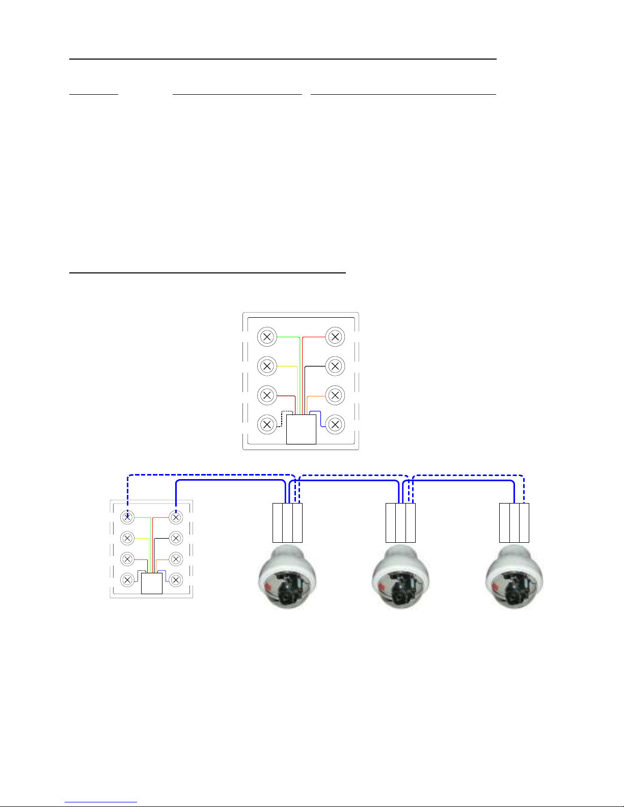
This port provides telemetry control via BBV RS422 (simplex). A Cat 5 RJ45 patch cable and breakout box is used to
connect the VISTA DOME CAMERAS via single twisted pair cable. It is possible to either wire the network in a daisy
chained or star configuration using an optional RS422 Starcard.
Page 22

TX1500 Manual V4.1 Oct 2011.doc Page 22 of 32 MATRIX PROGRAMMING/USER GUIDE
Telemtry Function
Protcoal BBV coax
BBV485 VCL coax Pelco coax VISTA coax VISTA 485 TP
Maximun cable
Distance
250M RG59
500M CT125
1200M
BELDEN 8723
250M RG59
275M CT125
250M RG59
275M CT125
250M RG59
275M CT125
1200M
BELDEN 8723
1#
REFER TO
RECEIVER MANUAL
REFER TO
RECEIVER MANUAL
N/A ENTER DOME
MENU
ENTER DOME
MENU
ENTER DOME
MENU
2#
REFER TO
RECEIVER MANUAL
REFER TO
RECEIVER MANUAL
N/A 180 FLIP EXIT DOME
MENU
EXIT DOME
MENU
3#
REFER TO
RECEIVER MANUAL
REFER TO
RECEIVER MANUAL
N/A N/A AUTOPAN Menu Esc Key no
Shift
4#
REFER TO
RECEIVER MANUAL
REFER TO
RECEIVER MANUAL
N/A SOFT RESTART RESET DOME Menu Esc Key
with Shift
5# N/A N/A N/A N/A N/A Freeze off
6# N/A N/A N/A N/A N/A Freeze on
7# N/A N/A N/A N/A N/A Color Mono
toggle
8# N/A N/A N/A N/A N/A 180 Flip
9# N/A N/A N/A N/A N/A Auto Focus toggle
10# N/A N/A N/A N/A N/A Auto Iris toggle
Number of
Presets Spproted
16 32 99 32 86
1 thought to 88
except 33 & 34
32
GOTO 33
PRESET
N/A N/A 180 FLIP N/A N/A N/A
GOTO 80
PRESET
N/A N/A AUTOFOCUS
ON
N/A N/A N/A
GOTO 81
PRESET
N/A N/A AUTOFOCUS
OFF
N/A N/A N/A
GOTO 91
PRESET
N/A N/A N/A N/A RUN Learn 1 N/A
GOTO 92
PRESET
N/A N/A N/A N/A RUN Learn 2 N/A
GOTO 93
PRESET
N/A N/A N/A N/A Program Learn 1 N/A
GOTO 94
PRESET
N/A N/A N/A N/A Program Learn 2 N/A
GOTO 99
PRESET
N/A
START
AUTOPAN
START
AUTOPAN
START
AUTOPAN
START
AUTOPAN
N/A
Iris Open N/A ENTER WHEN IN
THE MENU
N/A ENTER WHEN IN
THE MENU
ENTER WHEN IN
THE MENU
N/A
Iris Close N/A N/A N/A N/A ESCAPE N/A
Page 23
TX1500 Manual V4.1 Oct 2011.doc Page 23 of 32 MATRIX PROGRAMMING/USER GUIDE
SET PASSWORD
The default menu password of 999999 can be changed using this screen.
MAKE A NOTE OF THE NEW PIN.
The matrix software version is displayed at the top of the screen.
Select the New Pin Number area and type the new PIN. Move to the Confirm Number area and retype the PIN.
If the numbers match then a confirmation screen is displayed. Select EXIT to return to normal operation.
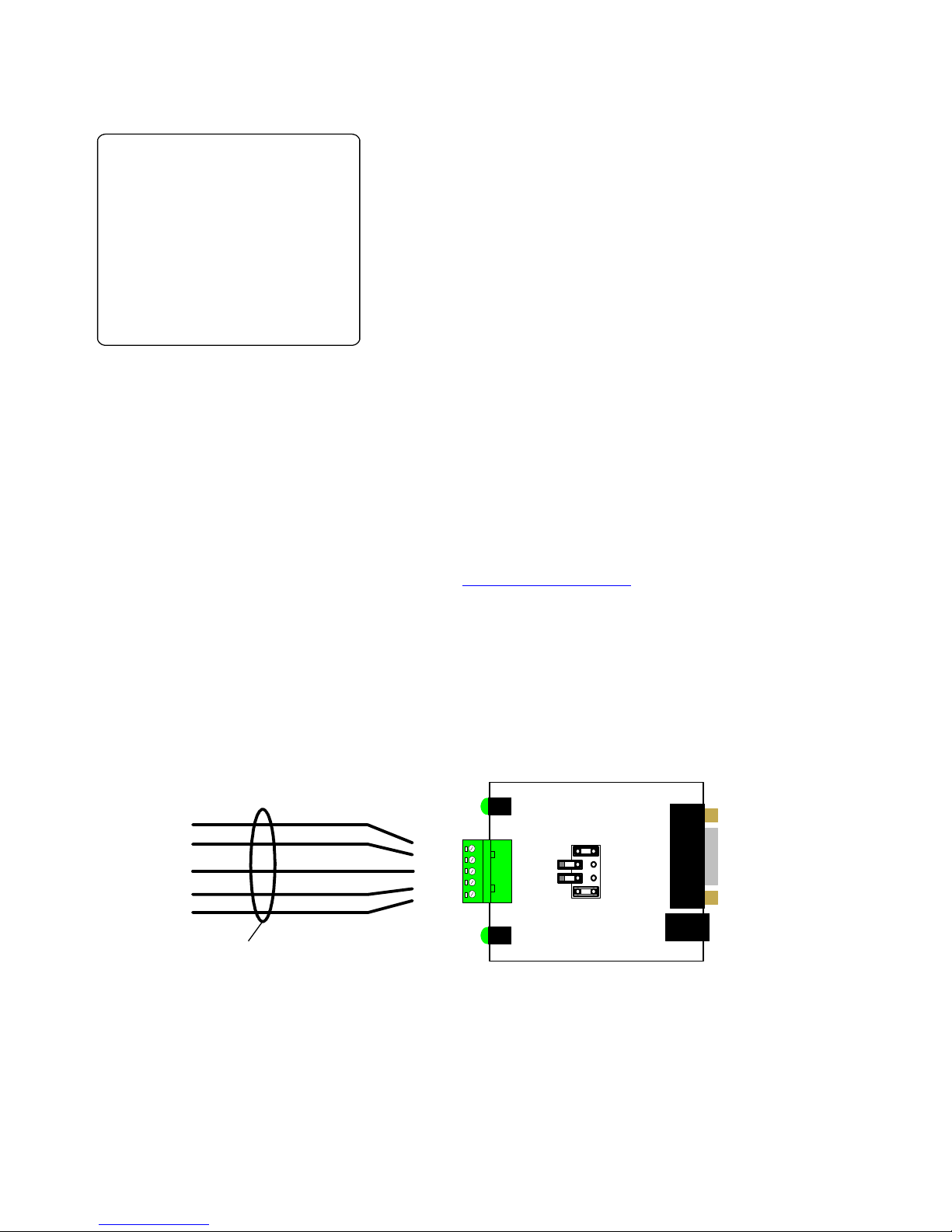
Upload
This feature stores the system parameters onto a pc to allow for backup. Data is transferred via the telemetry port.
Connection to a normal serial com port is made through a BBV RS232 Kit. PC application software is called
‘UP_DOWN_GUI’ and is available on the BBV website at www.support.bbvcctv.com or contact support
Download
This feature restores the system parameters from a pc. Data is transferred via the telemetry port.
Initialise System:
Cause the entire matrix programming to be deleted and default settings used.
This function must be used with great care, as ALL programming will be lost.
Plan view of TXLD PCB
BBV
RX
LO
HI
TX
PCB0313 Iss2
GND
TB/-(OUT)
TA/
+(OUT)
RA/+(IN)
RB/-(IN)
LD1-TX
LD2-RX
TO PC
COM PORT
RS232 in
DB9M
2 = RXD
5 = GND
9V SUPPLY IN
BROWN
GREEN
GREEN/WHITE
BLUE
BLUE/WHITE
TO
TELEMETRY
PORT
RJ45 PATCH CABLE
UPLOAD/DOWNLOAD CONNECTION TO PC
TX1500 version 3.5
Change Pin Number
New Pin Number ******
Confirm Number ******
Download
Upload
Initialise System
Return Exit
Page 24

TX1500 Manual V4.1 Oct 2011.doc Page 24 of 32 MATRIX PROGRAMMING/USER GUIDE
SYSTEM PARAMETERS
Used to program additional settings as follows:
System Parameters 2:
Displays the 2nd page of system parameters.
Menu Timeout:
Number of seconds of inactivity before the menu is automatically exited. Use +/- to cycle through values.
15, 20, 40, 60, 80, 100, 120, 150, 180, 200 or 250 seconds.
Program Timeout:
Number of seconds the Keypad will stay in programming mode after the PROGRAM key is pressed. This is to prevent
preset positions from being overwritten accidentally. Use +/- to cycle through values.
15, 20, 40, 60, 80, 100, 120, 150, 180, 200 or 250 seconds. It is recommended that a short time is selected.
Lockout Delay:
Number of seconds that the PTZ control of a camera is locked out after the last movement command. Used to prevent
two Keypads from ‘fighting’ for control of the same camera. Use +/- to cycle through values.
3, 5, 8, 10, 12, 15, 20, 30, 40, 60, 80, 100 or 250 seconds. 10 seconds would be an appropriate value.
Relay 0 Action:
Latching – Pressing the Keypad’s TRIANGLE key will toggle the state of the monitor output card relay.
Momentary – The relay will switch whilst the TRIANGLE key is pressed and switch back again when the key
is released.
System Parameters
System Parameters 2
Menu Timeout 60 Seconds
Program Timeout 20 Seconds
Lockout Delay 10 Seconds
Relay 0 Action Latching
Return
Page 25

TX1500 Manual V4.1 Oct 2011.doc Page 25 of 32 MATRIX PROGRAMMING/USER GUIDE
Sy stem Par ameters 2
Bu mp C amer as off
Re turn to patrol off
Pr iori ty K eyboard off
St artu p Ac tions
Mo nito rs i n sequence
None
Re turn
SYSTEM PARAMETERS 2
Used to program additional settings as follows:
Bump Cameras:
Selects the Keypad(s) that will remove the current camera from other monitors when controlled manually. This is to
prevent, for example, public display store monitors from displaying cameras that are following a suspect.
Use +/- to cycle through options:-
Off, Kbd 1, Kbd 2, Kbd 1 + 2, Kbd 3, Kbd 4, Kbd 1 + 2 + 3, Kbd 1+2+3+4
Return to patrol:
If set to on, the current camera will start a preset patrol 1, if supported, when another camera is selected. This is useful
for a system that has several cameras that should run preset patrols all the time that they are not controlled manually.
Priority Keypad:
A Keypad can be set that can take control of cameras at any time and is not locked out by other Keypads.
Startup Actions – Monitors:
This option allows selected monitors to resume sequence should the system power fail and restore. Use +/- to cycle
between the monitor choices.
None, 8, 78, 678, 5678, 45678, 345678, 2345678, or 12345678.
Page 26
TX1500 Manual V4.1 Oct 2011.doc Page 26 of 32 MATRIX PROGRAMMING/USER GUIDE
UP-THE-COAX RECEIVER SPECIFIC PROGRAMMING
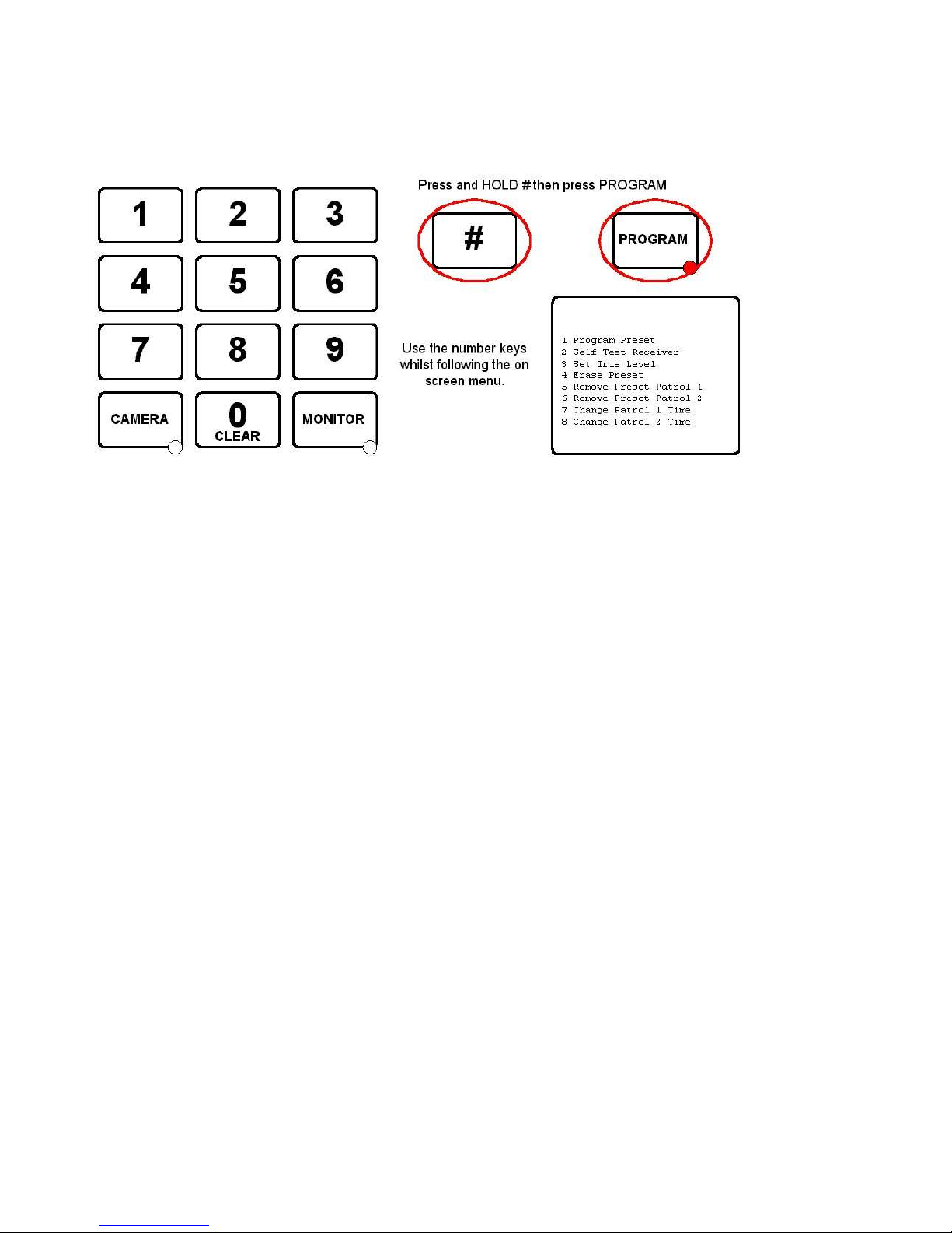
To program specific features of Rx100/200/300/400P/45X/55X up-the-coax receivers, the camera type must be set to
BBV COAX. Press and hold the ‘#’ key and tap the PROGRAM key to display the options. The PROGRAM key must be
enabled in the Keypad using SW1 switch 8 ON which is the factory default setting.
1 Program Preset 01-16
Enter 01 – 16 to program this preset position.
This is a legacy function to program a preset position and the preferred method is described on page 25.
2 Self Test Receiver
This will start the remote self test function, i.e. left/right/up/down etc on BBV up-the-coax receivers only.
3 Set Iris Level
Used with Rx300 Rx400P and Rx400DC to set the iris override output if fitted.
4 Erase Preset 01-16
Used to erase a preset from an RX100, RX400P or RX400DC. Enter 01 – 16 to erase the preset position.
5 Remove Preset Patrol 1
Enter 01 – 16 to remove the preset from preset patrol 1 with RX100, RX400P and RX400DC receivers
6 Remove Preset Patrol 2
As above but removes the preset position from patrol 2
7 Change Patrol 1 Time
Used to set the dwell time for patrol 1. 01 = RANDOM, 02 = 12 seconds, 03 = 24 seconds etc up to 16 = 180 seconds
when used with Rx100, Rx400P and Rx400DC receivers.
8 Change Patrol
As above but relates to preset patrol 2.
The menu will timeout and the PROGRAM key LED will turn OFF after several seconds to prevent accidental
reprogramming of the receiver.
Page 27
TX1500 Manual V4.1 Oct 2011.doc Page 27 of 32 MATRIX PROGRAMMING/USER GUIDE
TX1500 USER GUIDE
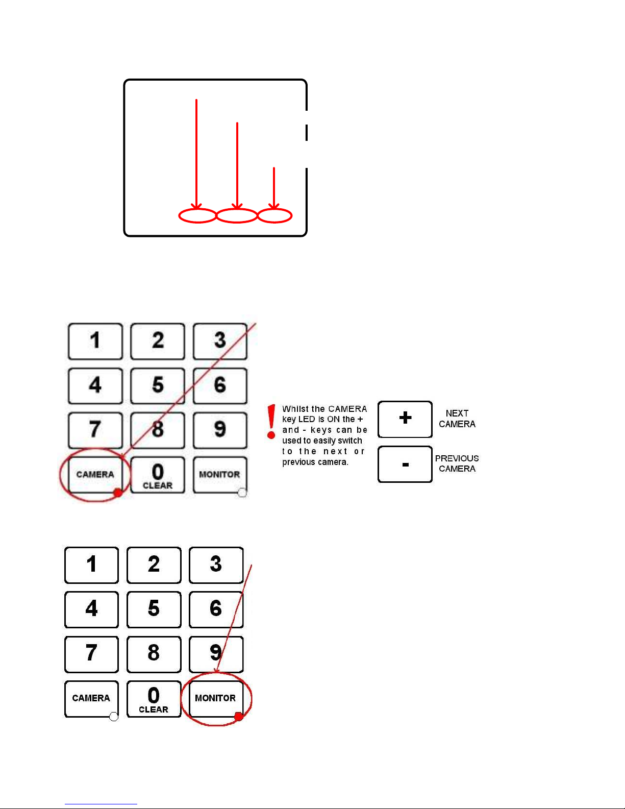
Monitor outputs 1,2,3 & 4 have an On Screen
Display as shown on the left.
The Monitor number along with current Camera
number is shown permanently.
Kbd is displayed whenever a Keypad is driving
a camera.
Monitor outputs 5,6,7 & 8 are not equipped with On Screen Displays and are generally used as spot, park or
public display monitors.
SELECTING A CAMERA
Use the number keys followed by the CAMERA key.
If the Keypad AND monitor are allowed to display the camera then the
current monitor will now display this camera.
If not then the command is ignored.
SELECTING A MONITOR
Use the number keys followed by the MONITOR key.
If the Keypad is not allowed to control this monitor then the command is
ignored.
Otherwise the Keypad can now control the camera displayed on the new
monitor
Mon 1 Cam 01 Kbd 1
Monitor Number
Current Camera Number
Keyboard Number
driving camera
Page 28
TX1500 Manual V4.1 Oct 2011.doc Page 28 of 32 MATRIX PROGRAMMING/USER GUIDE
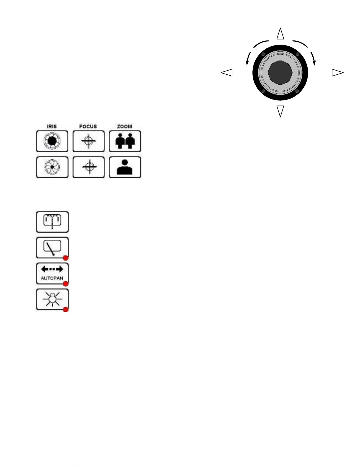
ZOOM OUT ZOOM IN
PAN LEFT PAN RIGHT
TILT DOWN
TILT UP
MOVING A CAMERA
JOYSTICK
The joystick is used to pan and tilt the camera and drive the lens zoom.
Moving the joystick left and right will pan the camera and moving the
joystick up and down will tilt the camera.
Rotating the joystick knob clockwise will zoom the lens IN and rotating
the knob anti-clockwise will zoom the lens OUT.
The joystick gives variable speed control
LENS KEYS
These keys are used to zoom and focus the lens and alter the iris if that
function has been provided.
Press a key for the desired function and release to stop.
AUXILIARY OUTPUTS
The WASH key is used to wash the camera housing’s glass if the feature has been provided.
The WIPER key is used to toggle the camera housing’s wiper ON/OFF
The function of the AUTOPAN key will vary depending upon the camera being controlled but mainly is
used to make the camera either pan from end stop to end stop or to run a preset patrol. Moving the
joystick left or right will turn autopan off.
The LIGHTS key is used to toggle any lights ON/OFF
Page 29
TX1500 Manual V4.1 Oct 2011.doc Page 29 of 32 MATRIX PROGRAMMING/USER GUIDE
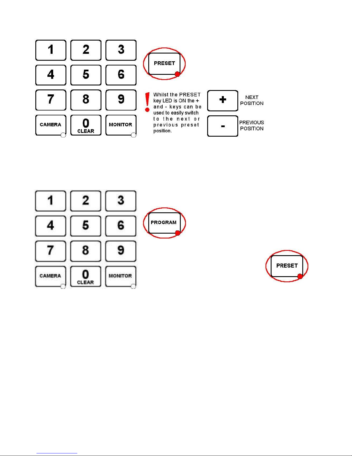
GOTO PRESET POSITION
Use the number keys followed by the PRESET key.
Preset positions are only available on moving cameras that are equipped for presets. Most will accept presets 1 – 16
although the TX1500 supports preset positions up to 99. This should be checked with your installing company.
PROGRAMMING A PRESET POSITION
Press the PROGRAM key to turn the PROGRAM key LED ON. The unit is
now in preset programming mode.
If the LED doesn’t light then this Keypad has been
prevented from programming presets by the
installation company.
Use the number keys followed by the PRESET
key to program the new preset position.
Page 30
TX1500 Manual V4.1 Oct 2011.doc Page 30 of 32 MATRIX PROGRAMMING/USER GUIDE
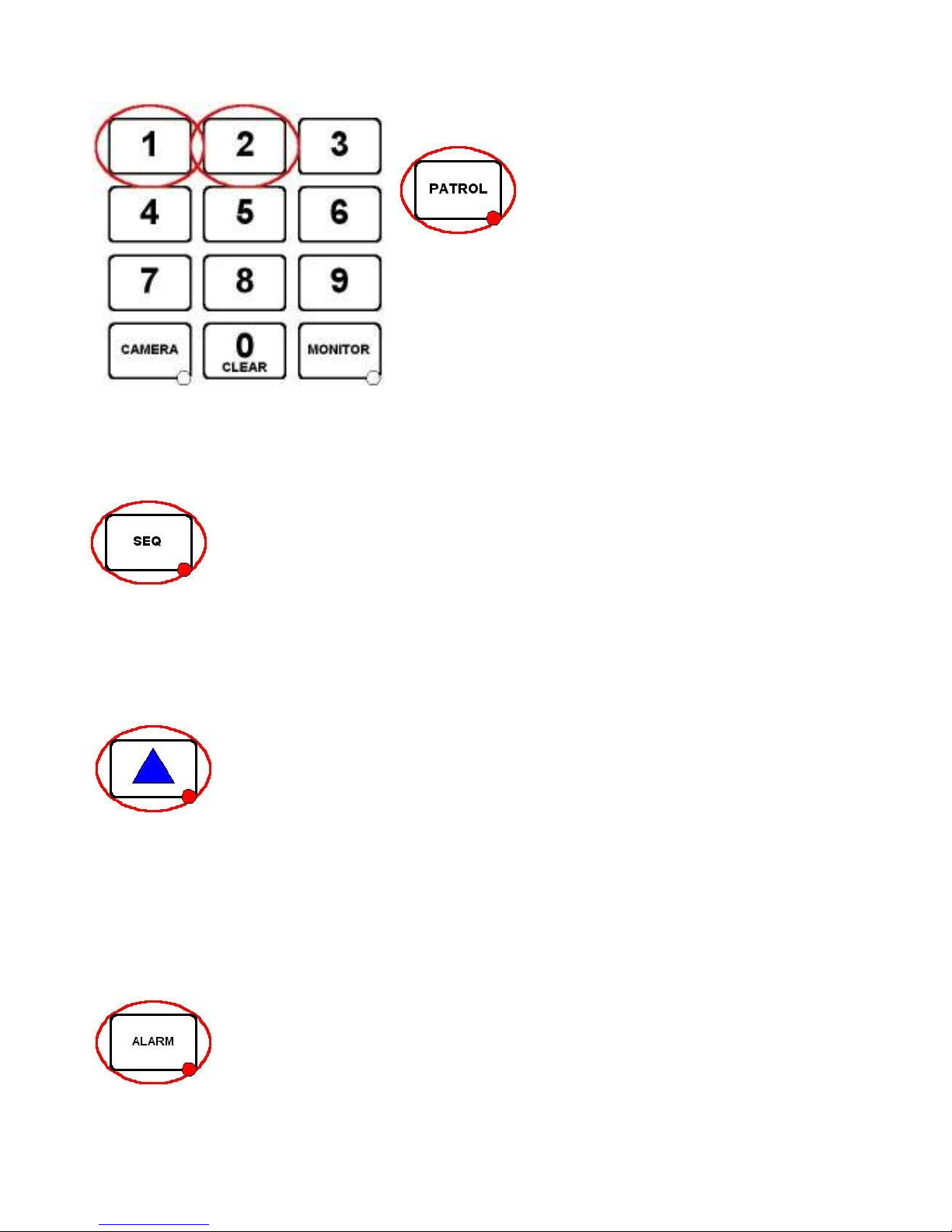
STARTING A PRESET PATROL
Press either 1 or 2 followed by the PATROL key.
The PATROL key LED will be ON whilst the current camera is running a
preset patrol.
To stop the camera from patrolling, move the joystick. The PATROL key
LED will now be OFF.
As with presets, patrols are only available on moving cameras that are equipped for presets. Certain dome cameras
offer enhanced patrol features that will be covered in the product addendum sheet for each specific dome type.
STARTING A MONITOR CAMERA SEQUENCE
Pressing the SEQ key will start a camera switching sequence on the current monitor. The SEQ key
LED indicates if the current monitor is running a sequence.
Each monitor can sequence individually and simultaneously.
The monitor sequence is programmed by the installation company using the system configuration menu.
To stop the sequence either press the SEQ key again to toggle the LED OFF or select another camera.
TRIANGLE / RELAY KEY
Use the TRIANGLE key to operate the TX1500 change over relay on the monitor out card. This can
be used for a variety of purposes. Your installation company will inform you of the specific function
for your site.
The relays on each alarm card can also be switched as follows:
2 TRIANGLE – relay 2 alarm card 1
3 TRIANGLE – relay 1 alarm card 2 4 TRIANGLE – relay 2 alarm card 2
5 TRIANGLE – relay 1 alarm card 3 6 TRIANGLE – relay 2 alarm card 3
7 TRIANGLE – relay 1 alarm card 4 8 TRIANGLE – relay 2 alarm card 4
9 TRIANGLE – relay 1 alarm card 5 10 TRIANGLE – relay 2 alarm card 5
11 TRIANGLE – relay 1 alarm card 6 12 TRIANGLE – relay 2 alarm card 6
ALARM KEY
If the system has been configured for KEY PRESS alarms by the installation company, following a
site alarm the ALARM key LED will be ON, the alarm monitor will display ‘alarm’ and the alarm
Keypad will beep.
The alarm is acknowledged by pressing the ALARM key. The alarm monitor/s will display the
camera/s programmed for this alarm.
Page 31
TX1500 Manual V4.1 Oct 2011.doc Page 31 of 32 TX1500/KBD SYSTEM KEYBOARD
TX1500/KBD - System Keypad
This Keypad provides control of the system and any cameras connected to the matrix. The Keypad
communicates through an RJ45 connector using BBV TX1500 protocol at 9600 baud on an RS422 link.
An internal 8 way DIP switch is used to set the Keypad address, RS422 termination and PROGRAM key
enable/disable.
Each Keypad must have a unique address between 1 and 4.
Keypads sharing the same address
will not be recognised by the matrix and unpredictable operation will occur.
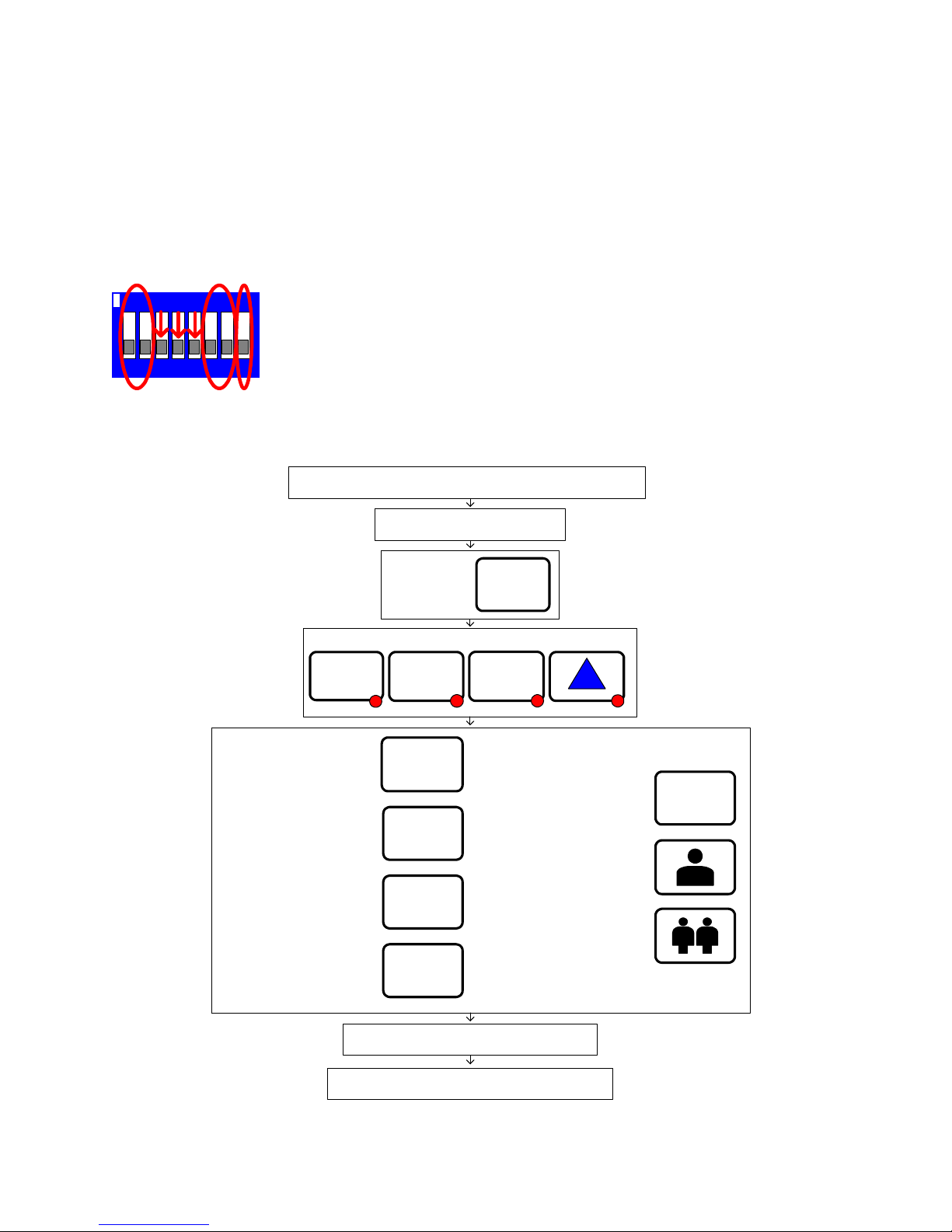
Joystick Calibration Procedure
If the joystick needs recalibration then follow instructions below:-
Your joystick has now been re-calibrated.
Remove power from your keyboard. Your power LED will now be off.
While powering up the keyboard:
Press and hold
0
These LEDs will flash:
SEQ
PATROL
PRESET
5
Ensure the joystick is in the
central position, then press
4
Pan fully left, while holding
the joystick fully left press
2
Tilt up, while holding the
joystick fully up press
6
Pan fully right, while holding
the joystick fully right press
8
Tilt down, while holding the
joystick fully down press
Twist joystick clockwise and
press the 'Zoom in' or press
Twist joystick counter clockwise
and press the 'Zoom out' or press
Power down for 10 seconds, and then power up.
The Keypad requires 9Vac/dc supply, minimum current of 100mA. A single Keypad can be supplied through a
patch cable from the matrix. Multiple or remote Keypads will need separate power supplies, which are supplied as
standard with each Keypad. Additional power supplies can be obtained from BBV.
Keyboard Address SW1 SW2
1 OFF OFF
2 ON OFF
3 OFF ON
4 ON ON
7 81 2 3 54 6
ON
SW 1-2 Keyboard Address
SW 3-5 OFF
SW 6 ON = PROGRAM & # key enable
SW 7&8 ON = BBUS Termination for end of line
Keyboard switch settings
Page 32
Extend your BBV Warranty from 12 months to 3 years
As of the 1st September 2008 BBV have offered our customers
the opportunity to extend the standard 12 month warranty to 3
years.
You must register for the extended warranty within 12 months
of the date of manufacture.
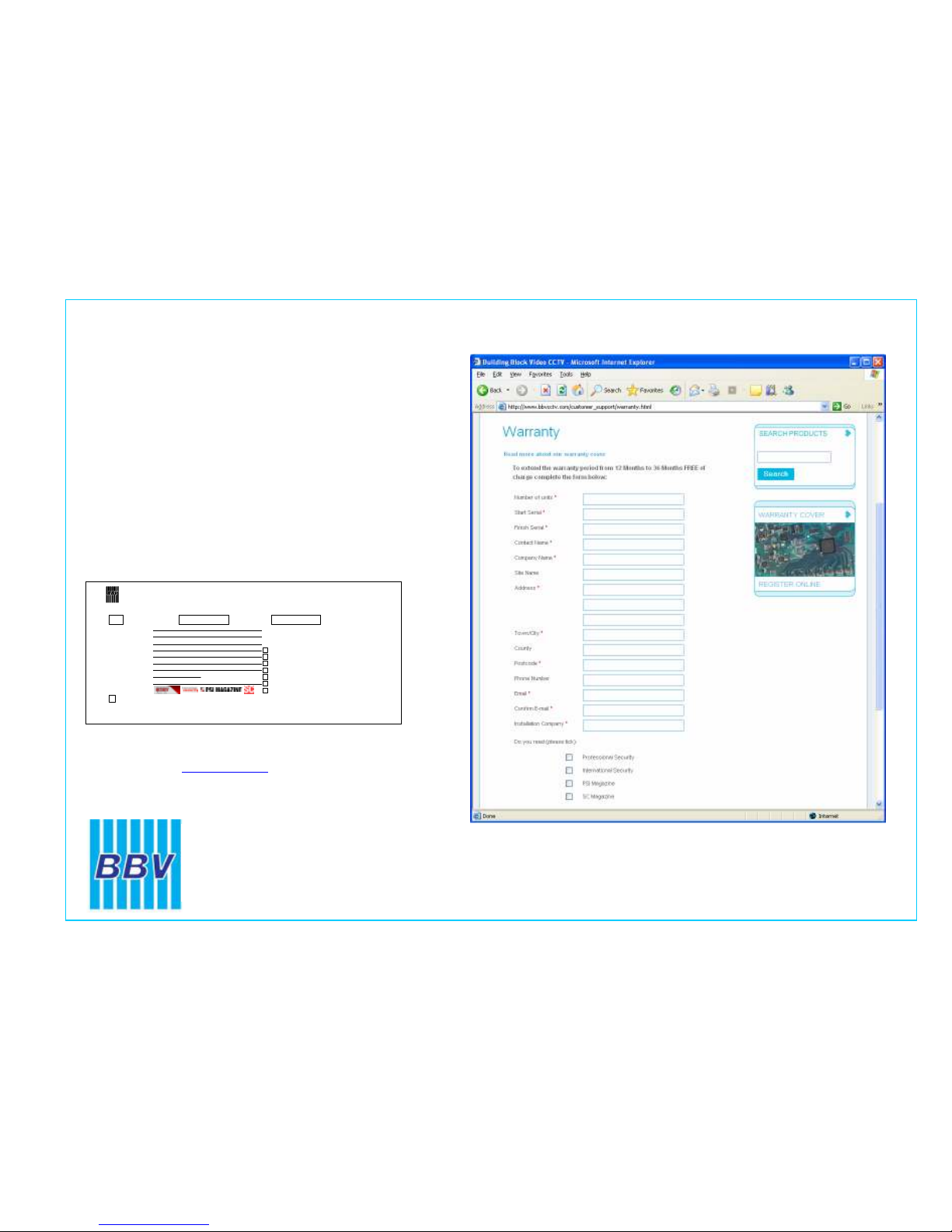
How to register for the 3 year warranty
Registering for the new, longer 3 year warranty term is quick
and easy.
Either:
Complete the warranty application card that comes in the box
with your BBV product, and return it FREEPOST to BBV:
VAT Reg. No. 621758439 Registered in England No. 2852921 Registered office: 17 Apex Park Diplocks Way Hailsham East Sussex UK BN27 3JU
If this card is returned with the serial number of the product and the Installation company
details BBV will extend the warranty period from 12 Months to 36 Months.
I do not require any other further product information,
BBV 3 Year Warranty
Please could you send me information
especially on:
Rx100s
Rx45x & Rx55x
FBM Video Matrices
Tx1500 Video Matrices
Starcard & Starcard Converters
BBV Quad
Pick A Point
Please refer to WWW.BBVCCTV.COM for terms, conditions & exclusions
Contact Name.
Company Name.
Phone Number.
Site Name.
Address 1.
Address 2.
Address 3.
e-mail address.
Post Code.
Do you read.
Number of Units, Start Serial No. Final Serial No.
Or alternatively:
Register online at: www.bbvcctv.com
Simply enter your details on the ‘Warranty Cover’ page.
Building Block Video Ltd
Tel: + 44 (0) 1323 842727
Fax: + 44 (0) 1323 842728
Support: + 44 (0) 1323 444600
www.bbvcctv.com
 Loading...