

Page 1

Building Block Video Ltd.,
Unit 1, Avocet Way,
Diplocks Industrial Estate,
Hailsham, East Sussex, UK.
Tel: +44 (0)1323 842727
Fax: +44 (0)1323 842728
Tech Support: +44 (0)1323 444600
web site: http://www.bbvcctv.com
Serial Data
Switch
Installation
Guide
BBVBBV
Model covered
SDS1
Page 2

1. PRE-INSTALLATION CHECKS AND SAFETY PROCEDURES
UNPACKING
Check Packaging - Upon taking delivery of the unit, inspect the packaging for signs
of damage. If damage has occurred, advise the carriers and/or the suppliers
immediately.
Check Contents - Upon taking delivery of the unit, unpack the unit carefully and
check that all the items are present and correct. If any items are missing or
damaged, contact your equipment dealer.
Retain Packaging - The shipping carton is the safest container in which to
transport the unit. Retain undamaged packaging for possible future use.
IMPORTANT SAFETY PRECAUTIONS
Read Instructions - All relevant safety, installation and operating instructions
should be read before attempting to install, connect or operate the unit.
Retain Instructions - All safety, installation and operating instructions should be
retained for future reference.
Heed Warnings - All warnings on the unit and in any relevant safety, installation or
operating instructions should be adhered to.
Cleaning - Unplug the unit from the power source before cleaning. Do not use
liquid cleaners or aerosol cleaners. Use a damp cloth for cleaning.
Attachments - Do not use attachments not recommended by the product
manufacturer as they may cause hazards.
Water and Moisture - Do not expose the internal electronics of this unit to water or
dampness; for example, in an unprotected outdoor installation, or in any area
classified as a wet location.
Power Sources - This unit should be operated only from the type of power source
indicated on the manufacturer’s label. If you are not sure of the type of power
supply you intend to use, consult your equipment dealer or local power company.
For units intended to operate from battery power or other sources, refer to operating
instructions.
Servicing - Servicing of the unit should only be undertaken by qualified service personnel.
Replacement Parts - If replacement parts are required, ensure that only
replacement parts recommended by the product manufacturer are used.
Safety Check - Upon completion of any service or repairs to the unit, safety checks
should be performed to ensure that the unit is in proper operating condition.
Pre-installation Checks - It is recommended that the unit be bench-tested prior to
installation on the site.
SDS1 Installation Guide. Issue 1.0 27 January 1999 Page 2
Page 3
SDS 1 TECHNICAL SPECIFICATION
Power Requirements +12V dc supplied by TX1000 Base Unit
Current Consumption 50mA (not including Keyboard)
Dimensions L 89mm x D 89mm x H 63mm
Weight 0.2Kg
Operating Temperature Range
-10°C to +40°C
SUPPLIED MALE DB9 LEAD PIN CONFIGURATION.
Pin Number Wire Colour
1 Red
2 Blue
3 Green
5 White
4,6,7,8 & 9 Not Connected
INTRODUCTION
The SDS1 is a serial data switch for use with the TX1000 series telemetry controllers when
using various video transmission systems or, if an extra control point is required using a slave
TX1000 Keyboard. The unit quite simply requires an “on-line” output (normally open volt free relay
contacts) on the video transmission transmitter or a manually operated switch in the case of a
second slave keyboard. This will switch the data flow to the TX1000 Base Unit from either the
remote site via the video transmission link or the second slave TX1000 keyboard. It is
supplied in a standard 45mm deep pattress for ease of installation and a lead for connection
to the TX1000 Base Unit is supplied. The TX1000 master keyboard will still be powered from
the TX1000 Base Unit. If the unit is used to switch to a second slave TX1000 keyboard the
second slave will need to use it’s own power supply which will be supplied. The TX1000 Base
Unit will only supply one TX1000 keyboard, any additional keyboards will require separate
power supplies.
INSTALLATION:
SDS1 Installation Guide. Issue 1.0 27 January 1999 Page 3
Page 4
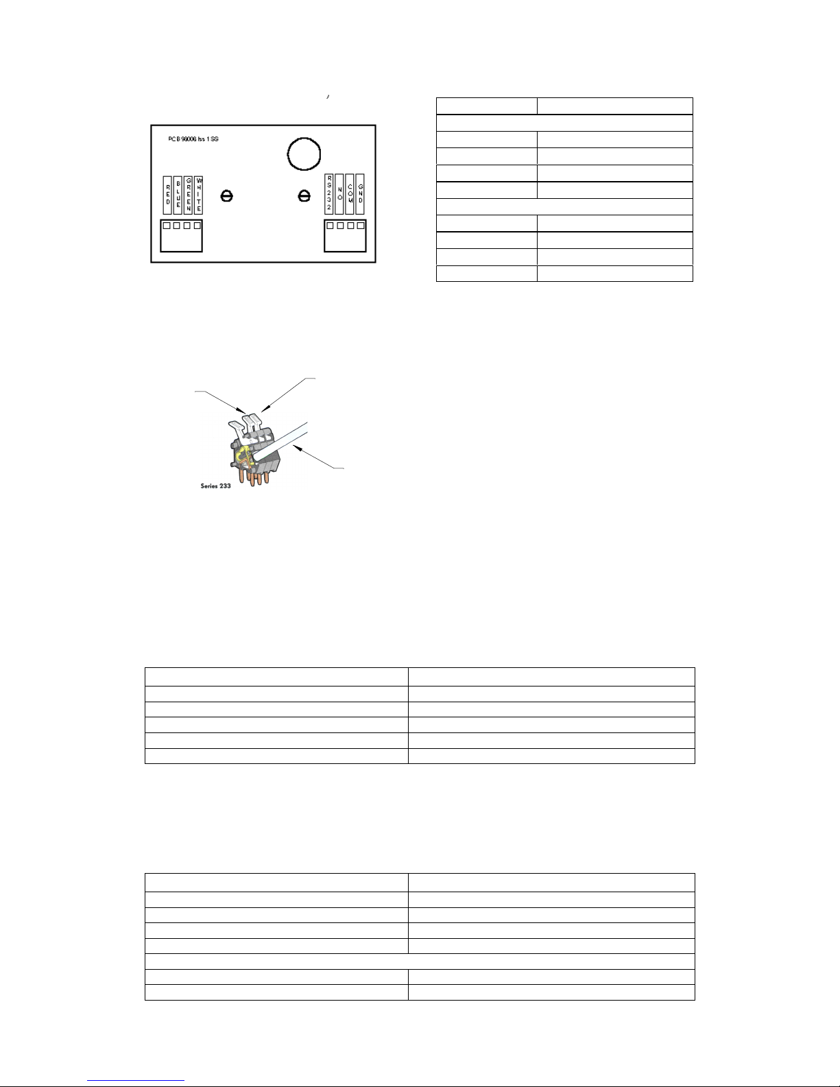
SDS1 Connections:
J1 DB9 MALE
TX1000 Keyboard
J2 TX1000 Base Unit Connections.
RED +12V
BLUE DATA RX
GREEN DATA TX
WHITE GND
J3 Video Transmission Equipment.
RS232 RS232 DATA IN
NO Normally-open relay contacts
COM Relay Contacts Return
GND 0V Ground Connection
J2 J3
View of SDS1 PCB.
Wago Connectors
The Wago series 233 PCB terminal block is
a simple-to-use method of attaching cables
to PCB’s quickly and easily. The correct
method of attachment is illustrated to the
left.
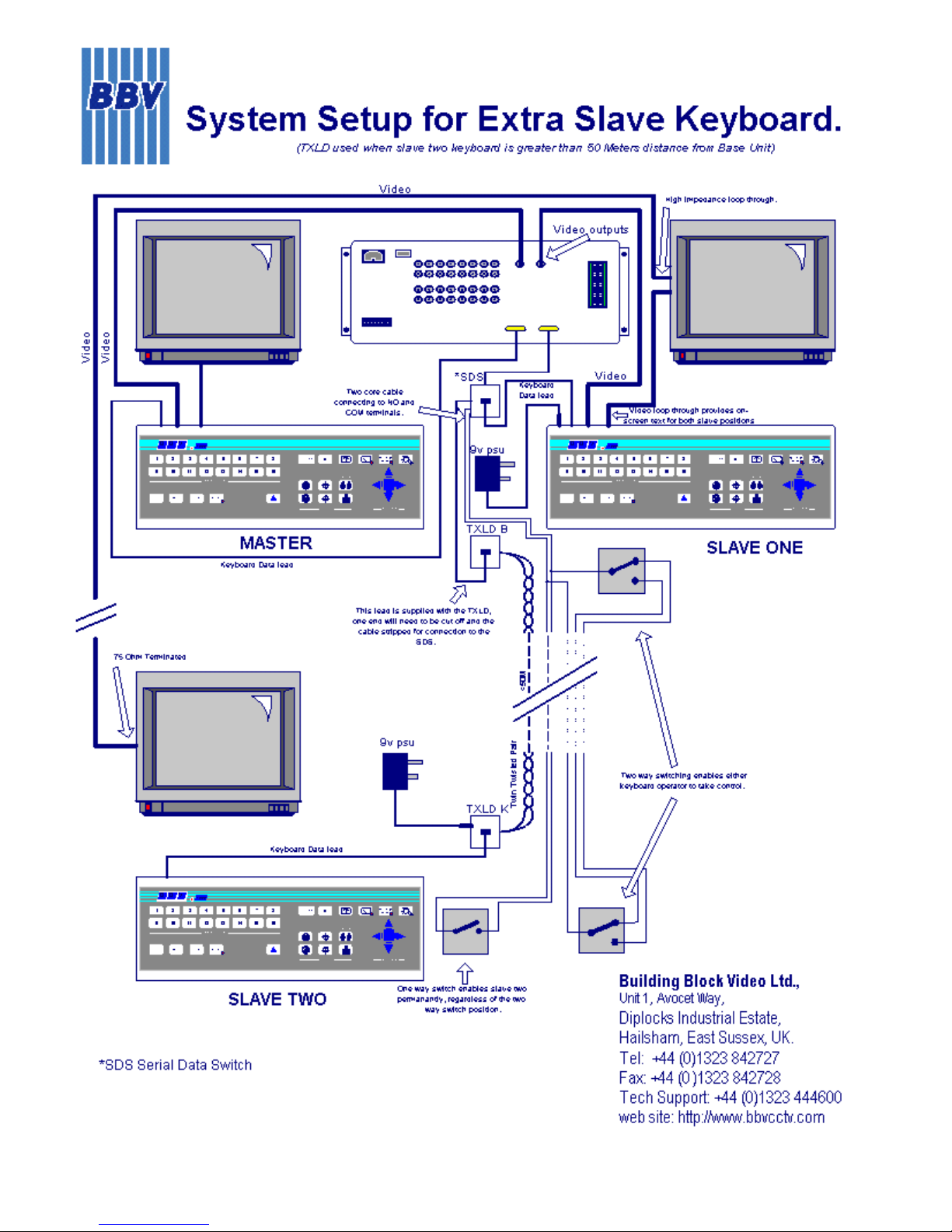
CONNECTION TO SLAVE KEYBOARD
When using the SDS1 to switch to a second TX1000 slave keyboard, an SPST switch will be
required to changeover the data input. This will connect between J3 NO and J3 COM. The
GREEN DATA TX from the TX1000 will need to be connected to the lead for the keyboard,
this enables LED function on the second slave. Using the leads supplied the female ended
lead connects to the TX1000 Base Unit and the coloured wires are connected to the SDS1 as
shown in the diagram. The male-ended lead connects to the Slave Keyboard lead and the
coloured wires are connected as follows:
Wire Colour (male ended) SDS1 Connection (refer to diagram)
Red Not Connected
Blue J3 RS232 DATA IN
Green J2 GREEN Data TX from base unit
White J3 GND
Orange & Black (if present) Not Connected
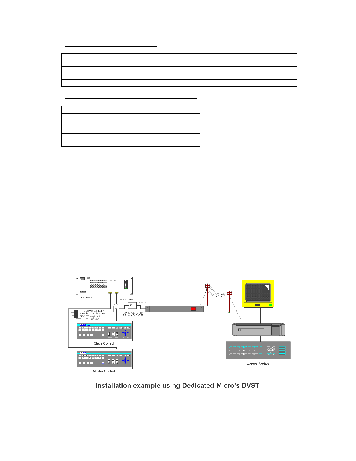
CONNECTION TO PL1 PROTOCOL CONVERTER WHEN USING DM’S DVST.
Using the leads supplied the female ended lead connects to the TX1000 Base Unit and the
coloured wires are connected to the SDS1 as shown in the diagram above. The male-ended
lead connects to the PL1 and the coloured wires are connected as follows:
Wire Colour (male ended) SDS1 Connection (refer to diagram)
Red J2 RED +12V
Blue, Black & Orange Not Connected
Green J3 RS232 IN
White J3 GND
On-line relay connections to Dedicated Micros DFT150/200
Pin 19 (37 way D type Alarm I/O Connector)
J3 NO
Pin 37 (37 way D type Alarm I/O Connector)
J3 COM
SDS1 Installation Guide. Issue 1.0 27 January 1999 Page 4
1. INSERT SCREWDRIVER
PRESS LEVER TO OPEN
CAGE CLAMP
2. INSERT STRIPPED
CONDUCTOR
RELEASE
LEVER 3.
Page 5
 Loading...