

Page 1
Building Block Video Ltd.,
17 Apex Park,
Diplocks Industrial Estate,
Hailsham, East Sussex, BN27 3JU UK.
Tel: +44(0)1323 842727
Fax: +44(0)1323 842728
Support: +44(0)1323 444600
www.bbvcctv.com
Rx10X Range
Multi Protocol Dome Interface Receiver
Installation
Guide
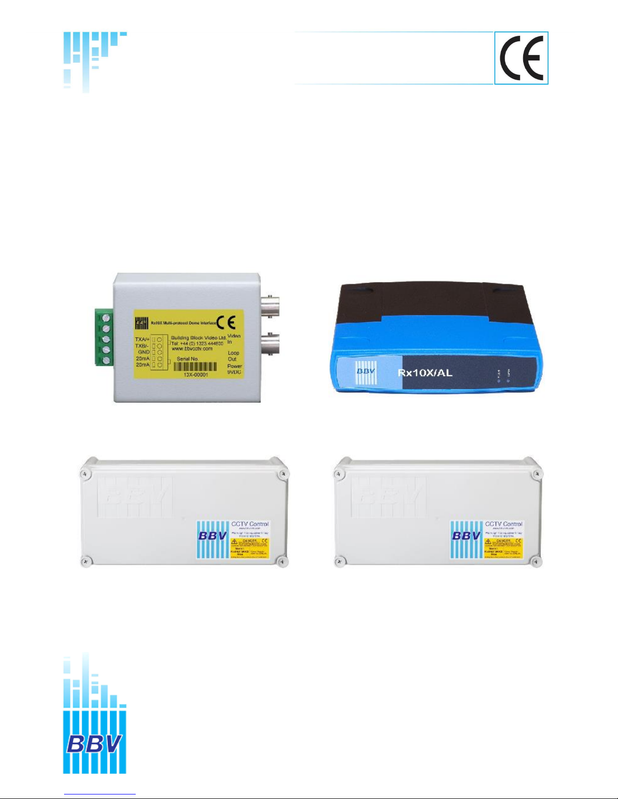
Rx10X Rx10X/AL
Rx10X/WBX Rx10X/24/WBX
Page 2

Rx10X installation manual V3.02 Page 2
Page 3

Rx10X installation manual V3.02 Page 3
TABLE OF CONTENTS
1.
Pre-installation Checks and Safety Procedures
4
Unpacking
4 Important safety precautions
4 + 5
2.
Introduction 6
General
6
Rx10X Technical specification
6 + 7 Cable connection method
8
Fig 1. Cable connection method
8
Cable types
8
3.
Installation
9
Rx10X connections
9
Fig 2.Rx10Xpcb connections
9
4.
Setup
10
Protocol& Mode selection
10
Protocol Selection Table
11 Options & Modes
12 Option & Mode Selection Table
12 Diagnostic aids
13
Fig 3.Test buttons
13
Cable length compensation
13
Fig 4. Launch amplifier
13
5.
System schematic diagrams
14
Fig 5. COAX Control
14
Fig 6. 20mA Control
14
Fig 7.Rx10X/AL Alarm Connections
15
Fig 8.Rx10X/WBX Auxiliary Connections
16 Rx10X in PC TEST MODE – Please read note
17
Fig 9. test mode
17
6.
Dome specific information
17
Dennard 2040, 2050, 2055 & 2060
18
GENIE ASD276 & ASD376
19
Honeywell Acuix
20
JVC TK-C655B, 675B, TK-C675E, TK-C675BE & 676
21
Merit Li-Lin PIH-717X/7000/7600/7625
22
Panasonic WV-CSR400, WV-CSR600 & WV-CSR650
23
Panasonic WV-CVS 850 & WV-CVS 960
24 Pelco Spectra & Esprit (D protocol) 2400
25 Pelco Spectra & Esprit (P protocol) 9600
26 Philips Auto Dome (RS232/485)
27 Sensormatic Ultra Dome 5, 6 & 7 (RS422 Only)
28
VCL Microsphere / Obiter range
29
Vicon Surveyor Range, SVFT& S10
30 Videcon VCP451&VHCD 860
31 Videcon VHSD 870
32
Vista Power Dome
33
7.
Troubleshooting
34
Page 4

Rx10X installation manual V3.02 Page 4
1. PRE-INSTALLATION CHECKS AND SAFETY PROCEDURES
UNPACKING
Check packaging - Upon taking delivery of the unit, inspect the packaging for signs of damage. If damage has
occurred, advise the carriers and/or the suppliers immediately.
Check contents - Upon taking delivery of the unit, unpack the unit carefully and check that all the items are
present and correct. If any items are missing or damaged, contact your equipment dealer.
Retain packaging - The shipping carton is the safest container in which to transport the unit. Retain undamaged
packaging for possible future use.
IMPORTANT SAFETY PRECAUTIONS
Read instructions - All relevant safety, installation and operating instructions should be read before attempting
to install, connect or operate the unit.
Retain Instructions - All safety, installation and operating instructions should be retained for future reference.
Heed warnings - All warnings on the unit and in any relevant safety, installation or operating instructions should
be adhered to.
Cleaning - Unplug the unit from the power outlet before cleaning. Do not use liquid cleaners or aerosol cleaners.
Use a damp cloth for cleaning.
Attachments - Do not use attachments not recommended by the product manufacturer as they may cause
hazards.
Water and moisture - Do not expose the internal electronics of this unit to water or dampness; for example, in
an unprotected outdoor installation, or in any area classified as a wet location.
Accessories - Do not attach this unit to an unstable stand, bracket or mount. The unit may fall, causing serious
injury to a person and serious damage to the unit.
Power sources - This unit should be operated only from the type of power source indicated on the manufacturer’s
label. If you are not sure of the type of power supply you intend to use, consult your equipment dealer or local
power company. For units intended to operate from battery power or other sources, refer to operating instructions.
Power connector - This unit is equipped with coaxial power connector mounted at the edge of the PCB for low
voltage power input. Do not attempt to alter this connector in any way.
Power cord protection - Power supply cords should be routed so that they are not likely to be trapped, pinched
or otherwise damaged by items in close proximity to them, whether inside the unit or outside it. Particular attention
should be paid to cords at plugs, connection units and the point of exit from the unit.
Overloading - Do not overload outlets and extension cords, as this can result in fire or electric shock.
Object and liquid entry - Never push objects of any kind into the unit, as they may touch dangerous voltage
points or short out parts that could result in fire or electric shock. Never spill liquid of any kind on or inside the
unit.
Servicing - Servicing of the unit should only be undertaken by qualified service personnel, as opening or
removing covers may expose you to dangerous voltages or other hazards.
Page 5

Rx10X installation manual V3.02 Page 5
Damage requiring service - Servicing by qualified personnel should be carried out under the following
conditions:
(a) When the power-supply cord or plug is damaged.
(b) If liquid has been spilled or objects have fallen into the unit
(c) If the internal electronics of the unit have been exposed to rain or water
(d) If the unit does not operate normally by following the operating instructions. Adjust only those controls
that are covered by the operating instructions, as improper adjustment of other controls may result in
damage and will often require extensive work by a qualified technician to restore the unit to normal
operation.
(e) If the unit has been dropped or the enclosure is damaged.
(f) If the unit exhibits a distinct change in performance. This indicates a need for service.
Replacement parts - If replacement parts are required, ensure that only replacement parts recommended by
the product manufacturer are used.
Safety check - Upon completion of any service or repairs to the unit, safety checks should be performed to
ensure that the unit is in proper operating condition.
Pre-installation checks - It is recommended that the unit be bench tested prior to installation on the site.
Safety during installation or servicing - Particular care should be taken to isolate the dome in order to prevent
operation while engineering work is being carried out on the Rx10X.
Adhere to safety standards - All normal safety precautions as laid down by British Standards and the Health
and Safety at Work Act should be observed.
WARNING
TO PREVENT DANGER OF FIRE OR SHOCK, DO NOT EXPOSE THE INTERNAL COMPONENTS OF THIS
EQUIPMENT TO RAIN OR MOISTURE.
Page 6
Rx10X installation manual V3.02 Page 6
2. INTRODUCTION
GENERAL
The Rx10X telemetry interface is designed to allow control of a variety of integrated dome cameras
using BBV’s range of up-the-coax telemetry transmitters.
Rx10X TECHNICAL SPECIFICATION
Power Requirements: Rx10X
12 – 36Vdc
24Vac from the dome supply(excluding the Dennard dome)
This unit is supplied with a 2.1mm Jack power fly lead. In addition a
PSU3 (12V 1A in line PSU) can be ordered from BBV
Rx10X/AL
12 – 24Vac or dc
24Vac from the dome supply (excluding the Dennard dome)
Rx10X/WBX
12 – 24V ac or dc
24Vac from the dome supply (excluding the Dennard dome)
Rx10X/24/WBX
230Vac Powered
24Vac 3A Output to power the dome and receiver (excluding the Dennard dome)
Current Consumption: 100mA maximum @ 12Vdc
Features: Rx10X
Two PCB construction.
Serial data output 2 wire RS232/422/485
Up to 16 preset positions can be stored using the Rx10X, depending
on the protocol, please read ahead for full details.
Rx10X/AL
Single PCB construction
Supports 4 local alarm inputs with 1 outputs
Up to 16 preset positions can be stored using the Rx10X, depending
on the protocol, please read ahead for full details.
Rx10X/WBX
Includes all the features of the Rx10X/AL
Additional relay capable of switching up to 1kW loads.
Supplied in an IP67 enclosure for external applications.
Rx10X/24/WBX
Includes all the features of the Rx10X/AL and Rx10X/WBX
24Vac 3A output to power both the dome and the receiver.
Engineering Facilities: Unit auto-tunes to the coaxial telemetry signal
7 Segment LED readout for continual system status
Data out LED
Video launch amplifier provided with Gain and Lift controls
Page 7

Rx10X installation manual V3.02 Page 7
Telemetry Signals: Telemetry signals either:
Up-the-coax max distances: 250M of RG59
500M of CT125/RG11
Or twisted pair 0-20mA current loop: 300 Ohm close loop impedance
maximum
Video Input: 1V p-p 75terminated input via BNC socket
Video Output: 1V p-p to V p-p 75 impedance via BNC socket
Presets: Up to 16 full scene preset positions can be stored within the interface
depending upon the model of dome
Dimensions:
Rx10X
Rx10X/AL
Rx10X/WBX
Rx10X/24/WBX
Length
69mm
102mm
365mm
365mm
Width
58mm
113mm
180mm
180mm
Height
36mm
34mm
100mm
100mm
Weight
Temperature range: -10° Celsius to +40°Celsius
99 grams
152grams
1.27Kg
2.54 Kg
Page 8
Rx10X installation manual V3.02 Page 8
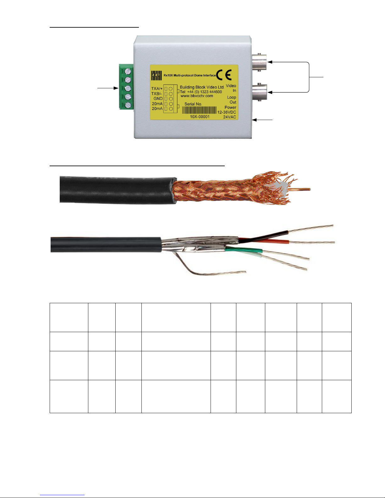
CABLE CONNECTION METHOD
75 ohm
BNCs
2.1mm coaxial
power connector.
This product is not
polarity sensitive
5 way screw
terminal plug
Video from
dome
Video to
controller
Fig 1. Cable connection method
CABLING RECOMMENDATIONS FOR THE Rx10X INTERFACE.
COAX
TWISTED PAIR
Cable Type
Inner
conductor
Dielectric Braiding
Outer
cover:
Impedance
Capacitance
External
Diameter
Attenuation
figures in
dB/100m at
5Mz.
RG59
COAX
Solid core
0.58mm
Polythene
Plain copper, >90% coverage
Black
PVC, UV
resistant
75 Ω ± 1Ω
53 pF/metre
nominal
6.2mm
nominal
≤2.1
dB/100m
CT125
COAX
Solid core
1.25mm
CellPE
SEMI Air
Spaced
0.15mm x 64 ( Braid ) BARE
COPPER + CU FOIL
COVERAGE:55%
PITCH : 65:80
Black
PVC, UV
resistant
75 Ω ± 1Ω
54 pF/metre
nominal
9.8mm
nominal
≤2.0
dB/100m
CW1308
TWISTED PAIR
Solid core
0.50mm
NA
All cables contain a screen comprising
of an aluminum tape with a backing that
ensures adhesion to the bedding
(Moisture Barrier). The tape screen is
applied in contact with a 0.80mm tinned
copper drain wire.
PVC,
500 pF/500
mtrs @ 1 kHz
(Max)
5.2mm
nominal
Page 9
Rx10X installation manual V3.02 Page 9
3. INSTALLATION
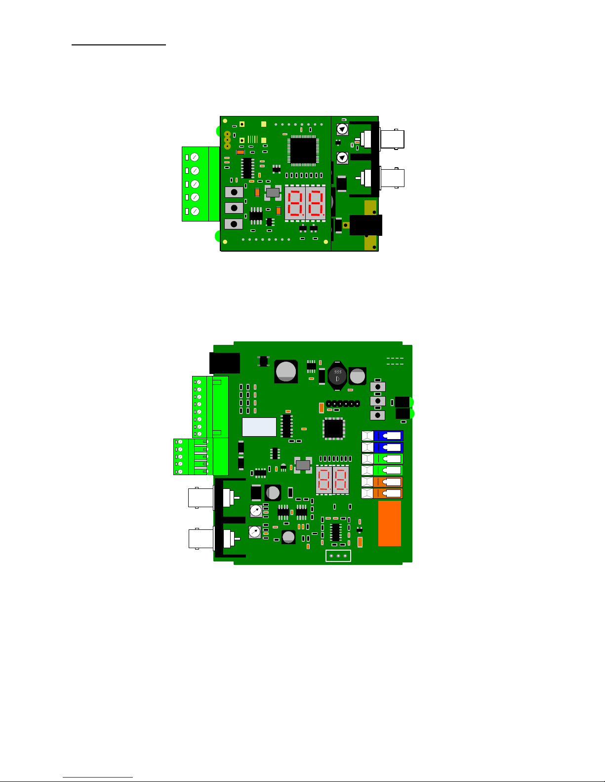
The Rx10X requires all connections to the PCB to be made by the installer, via terminal blocks or by plug
and socket. These connections are: power in, video in, video out, and serial data to dome. See Fig.2 below
for correct connections.
Fig 2.Rx10XPCB connections
Rx10X
Function
Connector
PCB
Type
Power in
J2
Bottom
2.1mm coaxial
Video in
J3
Bottom
BNC SOCKET
Video out
J5
Bottom
BNC SOCKET
20mA Twisted Pair Telemetry in
J6 Pins 1 & 2
Bottom
Green 5 Way IMO
Serial RS232/422/485 to dome
J6 Pins 3, 4 &5
Bottom
Green 5 Way IMO
Rx10X/AL
Rx10X/WBX
Rx10X/24/WBX
Function
Connector
Type
Auxiliary Relay
J2
Coloured Cage Clamp
Connector
Video in
J3
BNC SOCKET
Video out
J3
BNC SOCKET
Power in
J5
2.1mm coaxial
20mA Twisted Pair Telemetry in
J10 Pins 1 & 2
Green 5 Way IMO
Serial RS232/422/485 to dome
J10 Pins 3, 4 & 5
Green 5 Way IMO
Alarm Outputs
J14 Pins 1 & 2
Green 8 Way IMO
Alarm Inputs
J14 Pins 3, 4 ,5, 6, 7 & 8
Green 8 Way IMO
BBV
R
X
L
O
HI
T
X
GND
Video from
Dome
Video to
Controller
www.bbvcctv.com
DATA
TxA/+
TxB/-
Gnd
20mA IN
20mA IN
LD2
BBV
PCB08009
GAIN
LIFT
12VDC
100mA
J2
J5
J6
J1
J3
J2
www.bbvcctv.com
BBV
PCB08009
SW1
SW2
SW3
1
2
3
J5
VR1
J3
Data out LED
LIFT
GAIN
TX+
TX -
GND
20mA
20mA
Video from
Dome
Video to
Controller
SW LIVE GND NEUTRAL
DATA
SW1
SW2
SW3
A1
A2
A3
A4
GND
GND
AOUT
AOUT
TX+
TX+
GND
20mA
20mA
RY2A
X1
BBV
Www.bbvcctv.com
4A 230V MAX
IND1
J2
RL2
VR3
J5
BR1
DISP1
U6
DATA OUT
Alarm 1
Alarm 2
Alarm 3
Alarm 4
Ground
Ground
AOUT
AOUT
12 – 24 V
ac or dc
POWER
Page 10
Rx10X installation manual V3.02 Page 10
4. SETUP
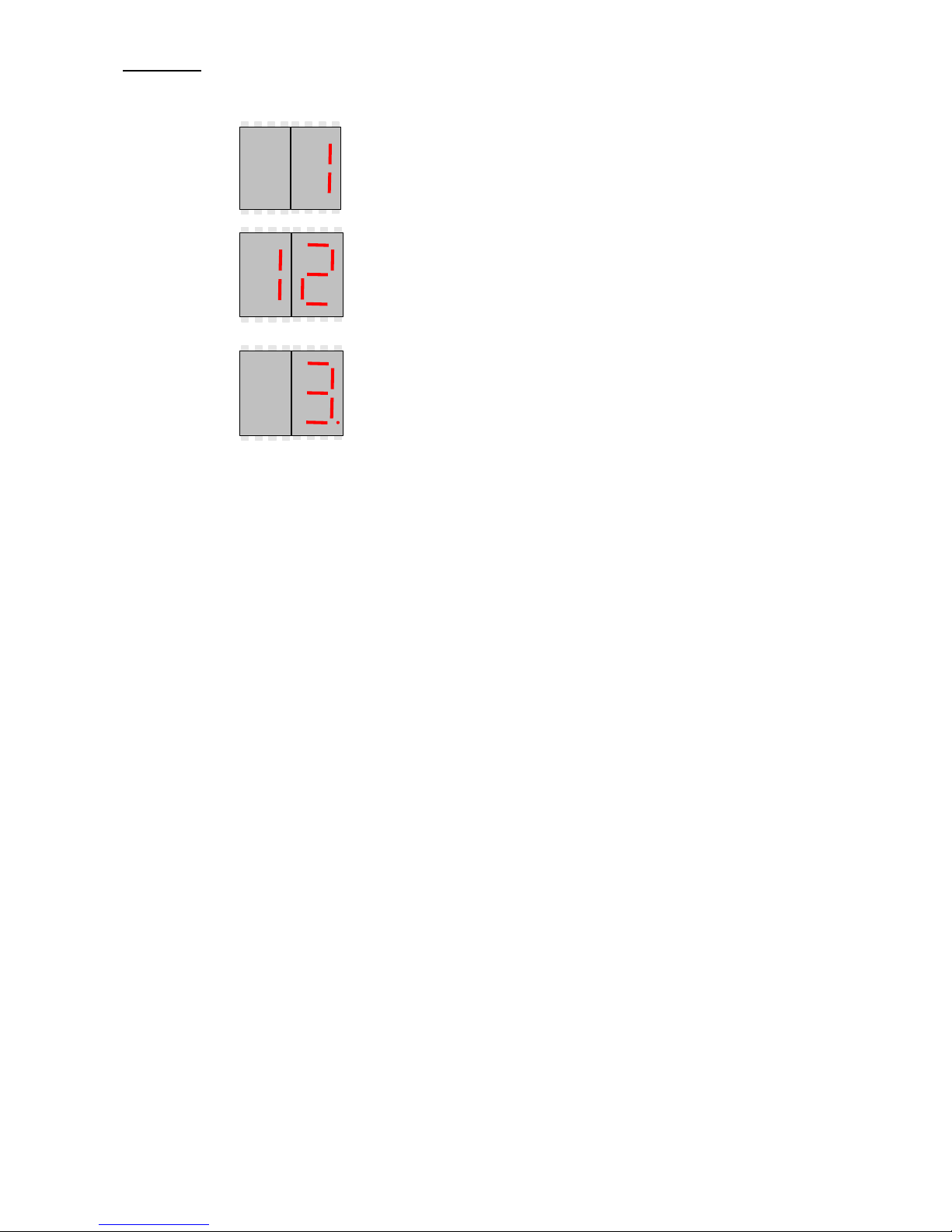
On power up the unit will display the following information in order:
Version This would mean version 1
Protocol This would mean Protocol 12
Mode This would mean Mode 3
To change either the protocol or the options value:
Press the centre button (sw2) a value between 0 and 32 will be displayed.
Protocol select (protocol selection table is on page 11)
By holding the top button (sw1) down the value shown on the display will decrement through the available values.
By holding the bottom button (sw3) down the value shown on the display will increment through the available
values.
Once the required value is displayed then press the centre button(sw2) again and the display will show‘- -‘, to
indicate that the value has been entered .Then the option value will then be displayed.
Mode select (mode selection table is on page 12)
By holding the top button (sw1) down the value shown on the display will decrement through the available values.
By holding the bottom button (sw3) down the value shown on the display will increment through the available
values.
Once the required value is displayed then press the centre button(sw2) again and the display will show ‘- -‘, to
indicate that the value has been entered. It will then show the software version, the protocol & finally the option
number. Then you will see a red flashing dot to show the Rx10X is running.
Page 11
Rx10X installation manual V3.02 Page 11
Protocol Selection Table
Protocol
Data out
Dome or Camera
Protocol
Number
Camera
Address
Page
Number
VISTA Up
The Coax
Supported
Laptop De-Bug**
38400,N,8,1
PC TEST
00
None
17
NO
Pelco P
9600,N,8,1
Spectra & Esprit
01
01
26
YES
Pelco D
2400,N,8,1
Spectra & Esprit
02
01
25
NO
VCL485
9600,N,8,1
Microsphere & Orbiter range
03
01
29
YES
Vicon
9600,N,8,2
Surveyor Range, SVFT & S10
04
01
30
NO
Videcon
9600,N,8,1
VCP451& VHCD 860
05
01
31
NO
Videcon
2400,N,8,1
VHSD870
06
01
32
NO
Sensormatic RS422
4800,N,8,2
Ultra Dome 5, 6, 7& 8
07
01
28
YES
Dennard
9600,N,8,1
2040, 2050, 2055 & 2060
08
01
18
NO
Panasonic 650
19200,N,8,1
WV-CSR400 WV-CSR600
& WV-CSR650
09
01
23
NO
Panasonic 850
19200,N,8,1
WV-CVS 850 & WV-CVS 960
10
01
24
YES
JVC
9600,E,8,1
TK-C655B, 675B, TK-C675E,
TK-C675BE & 676
11
01
21
YES
Vista
9600,N,8,1
Power Dome Range
12
01
33
NO
Philips RS232/485
9600,N,8,1
LTC 0929/15
13
01
27
NO
Genie ASD276 &
ASD376
2400,N,8,1
ASD276 & ASD376
14
01
19
NO
Honeywell Acuix
9600,N,8,1
Acuix ES
15
01
20
NO
Merit Li-Lin
9600,N,8,1
PIH-717X/7000/7600/7625
16
01
22
NO
Please note VISTA Up The Coax supported dome protocols have been tested on a
limited number of VISTA control system it is the responsibility of the customer to
prove compatibility with the Rx10X and you systems particular VISTA transmitter.
** To enable the Rx10X to go into it’s De-Bug mode you must set it to: Protocol – 0, Mode – 1
If mode 1 is not selected the Rx10X will revert to protocol 1 on reboot**
Page 12
Rx10X installation manual V3.02 Page 12
Options & Modes
Each protocol supports different features which are triggered by selecting different modes in the Rx10X.
The following table indicates how to choose the correct mode number. Please refer the dome specific
information later in the manual the different mode selects different options to be implemented.
For example mode number 01 has just option 1 on. This will cause the dome to go back to preset 1 after 5
minutes of inactivity. This will stop a patrol that might be started by a keypad.
Option 5 Vista mode this allows the following domes JVC TK-C655B, 675B, TK-C675E, TK-C675BE &
676, Panasonic WV-CVS 850 & WV-CVS 960, Pelco P-Spectra & Esprit, Sensormatic Ultra Dome 5, 6 &
7 and VCL Microsphere & Orbiter range to be controlled by Vista up the coax.
Option& Mode Selection Table
Option 5
Option 4
Option 3
Option 2
Option 1
Mode
Number
OFF
OFF
OFF
OFF
OFF
00
OFF
OFF
OFF
OFF
ON
01
OFF
OFF
OFF
ON
OFF
02
OFF
OFF
OFF
ON
ON
03
OFF
OFF
ON
OFF
OFF
04
OFF
OFF
ON
OFF
ON
05
OFF
OFF
ON
ON
OFF
06
OFF
OFF
ON
ON
ON
07
OFF
ON
OFF
OFF
OFF
08
OFF
ON
OFF
OFF
ON
09
OFF
ON
OFF
ON
OFF
10
OFF
ON
OFF
ON
ON
11
OFF
ON
ON
OFF
OFF
12
OFF
ON
ON
OFF
ON
13
OFF
ON
ON
ON
OFF
14
OFF
ON
ON
ON
ON
15
ON
OFF
OFF
OFF
OFF
16
ON
OFF
OFF
OFF
ON
17
ON
OFF
OFF
ON
OFF
18
ON
OFF
OFF
ON
ON
19
ON
OFF
ON
OFF
OFF
20
ON
OFF
ON
OFF
ON
21
ON
OFF
ON
ON
OFF
22
ON
OFF
ON
ON
ON
23
ON
ON
OFF
OFF
OFF
24
ON
ON
OFF
OFF
ON
25
ON
ON
OFF
ON
OFF
26
ON
ON
OFF
ON
ON
27
ON
ON
ON
OFF
OFF
28
ON
ON
ON
OFF
ON
29
ON
ON
ON
ON
OFF
30
ON
ON
ON
ON
ON
31
Page 13
Rx10X installation manual V3.02 Page 13
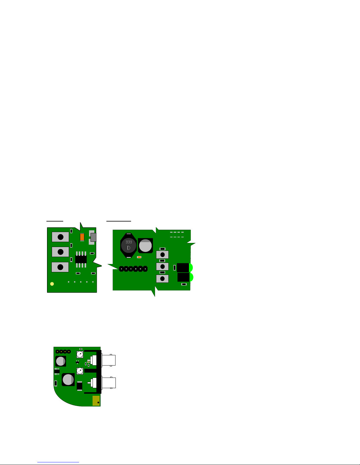
SW1 Makes the dome Pan Left
SW3 Makes the dome Pan Right
DIAGNOSTIC AIDS
A 7 segment LED display is mounted on the top PCB this gives system status information. The meanings
of the values are as follows:
The value
Description
The value
Description
.
All OK(Flashing red dot)
9.0
No Video
L.
Sending a pan left to the dome
9.1*
No telemetry carrier detected
r.
Sending a pan right to the dome
9.2
No coax start bit detected
.u
Sending a tilt up to the dome
9.3
Coax parity error
.d
Sending a down up to the dome
9.4
No coax stop bit detected or frame error
9.5
Twisted pair parity error
9.6
Twisted pair over run error
*NB Not all transmitters provide a constant telemetry signal, therefore seeing error 9.1 until telemetry is sent is
normal.
This error will be seen if using a CTI/1, TX1500 and will also occur if the camera is not selected on a TX1000.
During the operation of the unit you will see a red flashing dot in the middle of the 7 segment LED display this
means the unit is working.
The Rx10X is designed to auto-tune and compensate for any discrepancies in the transmitted telemetry
signal; there are no further adjustments that need to be made.
The Rx10X has an in built facility that enables you to test the communications between the Rx10X& the
dome. This is done by pressing SW1 and the dome will pan left or press SW3 and the dome will pan right,
on releasing the button the dome will stop.
Fig 3.Test Buttons
Rx10X Rx10X/AL
SW1
SW2
SW3
1
2
3
SW1 Makes the dome Pan Left
SW3 Makes the dome Pan Right
VIDEO LAUNCH AMPLIFIER AND CABLE LENGTH COMPENSATION
The interface features a video launch amplifier with two variable controls situated close to the BNC
connectors: Lift and Gain. These are pre-adjusted for a cable distance of 500m of CT125, and are
adjustable to compensate for video detail or signal losses if and when longer or shorter cable lengths are
used to connect the telemetry transmitter to the interface.
Fig 4. Launch Amplifier
The purpose of each control is:
GAIN varies the overall signal level.
LIFT boosts the high frequency component of the video signal.
If the high frequency component is too low, picture appears
‘washed out’ and lacking detail.
Default position adjusted for 500M of CT125.
For shorter cable lengths, turn the GAIN control anti-clockwise until 1V p-p is present at the telemetry
transmitter. For longer cable lengths, turn the GAIN control clockwise until 1V p-p is present at the telemetry
transmitter.
GAIN
LIFT
Video from
Dome
Video to
Controller
J2
J5
J3
DATA
SW1
SW2
SW3
IND1
Page 14
Rx10X installation manual V3.02 Page 14
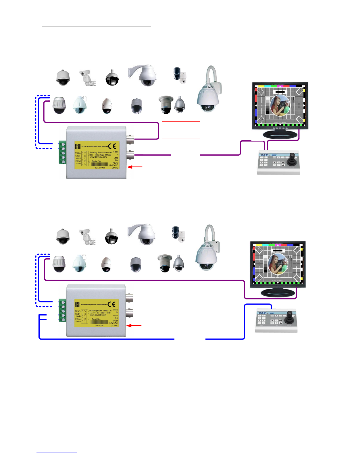
5.SYSTEM SCHEMATIC DIAGRAMS
Fig 5.COAX Control
JVC TX_C676
Pelco Domes Pelco Esprit
Bosch DomesAll Dennard Domes Panasonic
Sensormatic
VCL
Honeywell
Vista Powerdome
Videcon
BBV
R
X
L
O
GND
DATA
GAIN
LIFT
<250m RG59
<500m CT125
TxA
TxB
Gnd
20mA IN
20mA IN
Video to
Controller
Dome
Video from
12VDC
100mA
12 – 36Vdc or 24Vac
Maximum run
between Rx10X and
Dome: <5m
Fig 6.20mA Control
LD2
JVC TX_C676
Pelco Domes Pelco Esprit
Bosch DomesAll Dennard Domes Panasonic
Sensormatic
VCL
Honeywell
Vista Powerdome
Videcon
BBV
R
X
L
O
GND
DATA
GAIN
LIFT
TxA
TxB
Gnd
20mA IN
20mA IN
12VDC
100mA
300ohm closed
resistance
12 – 36Vdc or 24Vac
Page 15
Rx10X installation manual V3.02 Page 15
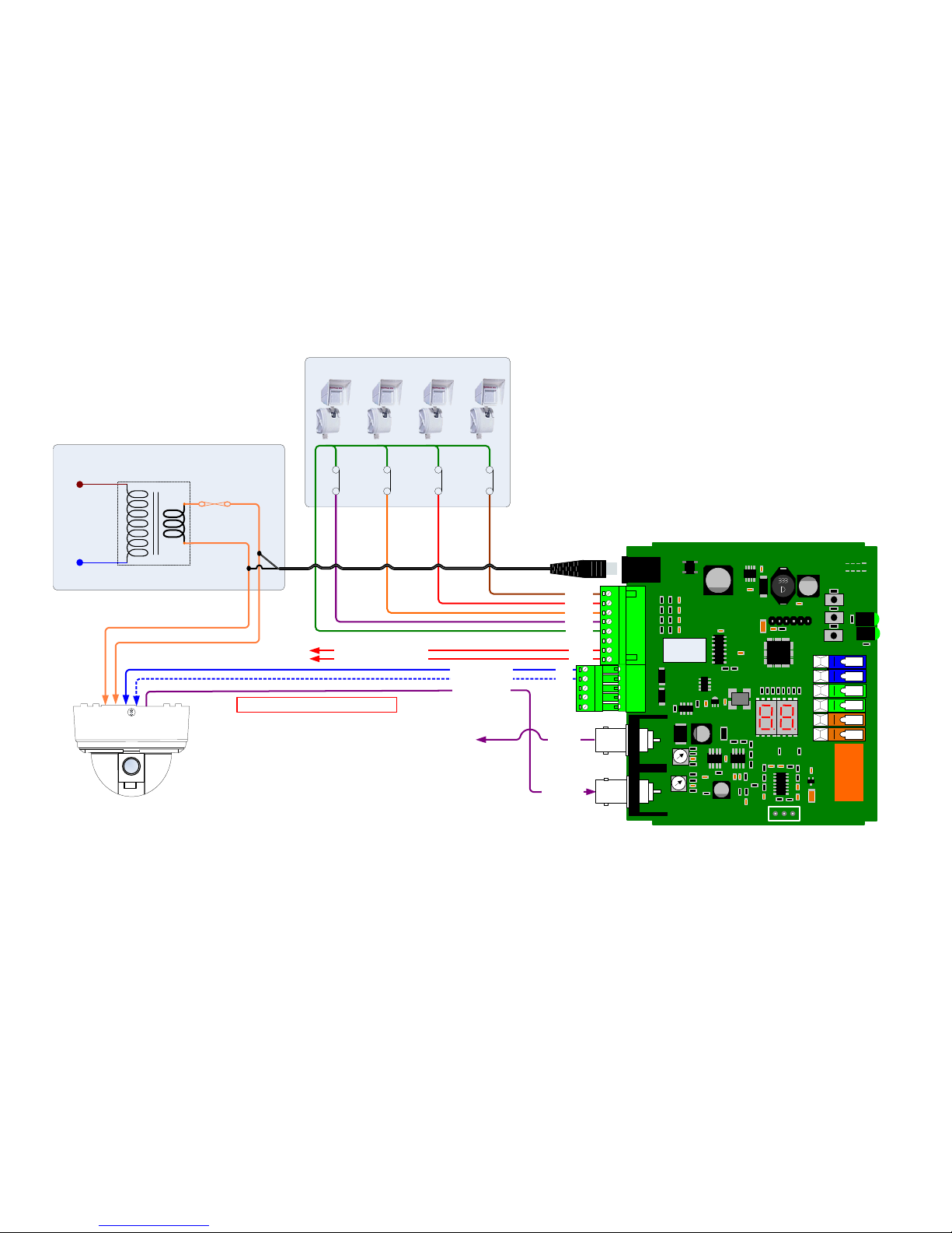
Fig 7.Rx10X/AL Alarm Connections
oData + to the domeo
oData - to the domeO
oVideo from domeO
230V 50Hz
NEUTRAL
LIVE
24V 50Hz
FUSE
Dome Power supply
PIR
Normally
closed
PIR
Normally
closed
LIFT
GAIN
oTX+o
oTX -o
GND
20mA
20mA
SW LIVE GND NEUTRAL
DATA
SW1
SW2
SW3
A1
A2
A3
A4
GND
GND
AOUT
AOUT
TX+
TX+
GND
20mA
20mA
RY2A
X1
BBV
Www.bbvcctv.com
4A 230V MAX
IND1
J2
RL2
VR3
J5
BR1
DISP1
U6
AAlarm 1A
AAlarm 2A
AAlarm 3A
AAlarm 4A
AGroundA
GroundA
AAOUTA
AAOUTA
12 – 24 V ac
or dc
OVideo fromO
DomeO
PIR
Normally
closed
PIR
Normally
closed
PIR or other normally closed alarm input to the Rx10X/AL
oNormaly closed alarm outputo
OVideo too
Controllero
Maximum run between Rx10X and Dome: <5m
Page 16
Rx10X installation manual V3.02 Page 16
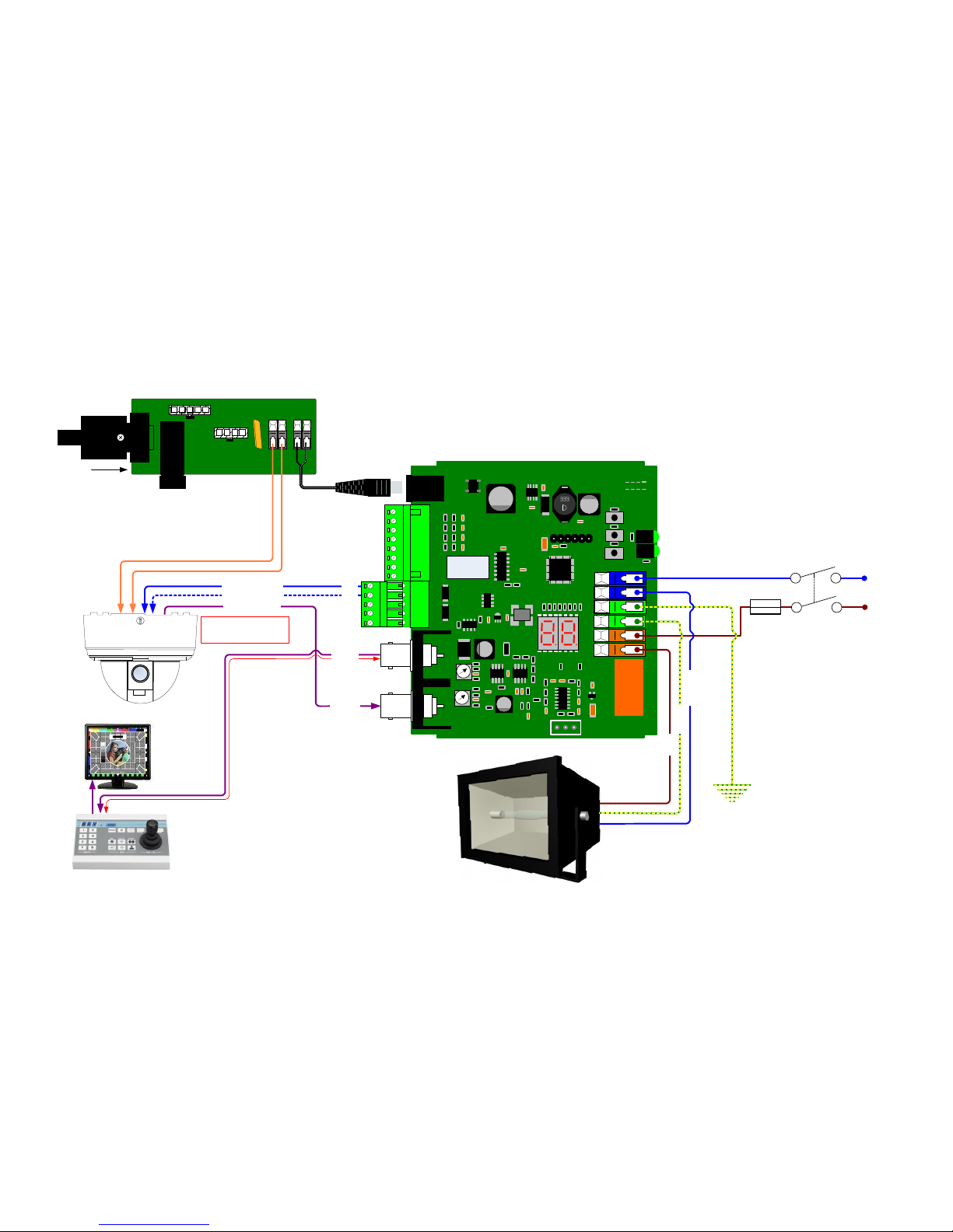
Fig 8.Rx10X/WBX Auxiliary Connections
LIFT
GAIN
GND
20mA
20mA
SW LIVE GND NEUTRAL
DATA
SW1
SW2
SW3
A1
A2
A3
A4
GND
GND
AOUT
AOUT
TX+
TX+
GND
20mA
20mA
RY2A
X1
BBV
Www.bbvcctv.com
4A 230V MAX
IND1
J2
RL2
VR3
J5
BR1
DISP1
U6
Alarm 1
Alarm 2
Alarm 3
Alarm 4
Ground
Ground
AOUT
AOUT
12 – 24 V ac
or dc
Double Pole,
Single Throw
Switch
5 A
Fuse
Up to 1kW flood light
oData + to the domeo
oData - to the domeO
oVideo from domeO
Maximum Coax Cable run from Control
system to RX10X:
RG59 <250m
CT125 <500m
oTX+o
oTX -o
Video to
Controller
Video from
Dome
p LIVE p
p EARTH p
p NEUTRAL p
N
L
FUSE 240V 630mA
24VAC 24VAC
230V IN
PCB11007 Iss1
BBV
www.bbvcctv.com
Maximum run between
Rx10X and dome: <5m
Page 17
Rx10X installation manual V3.02 Page 17
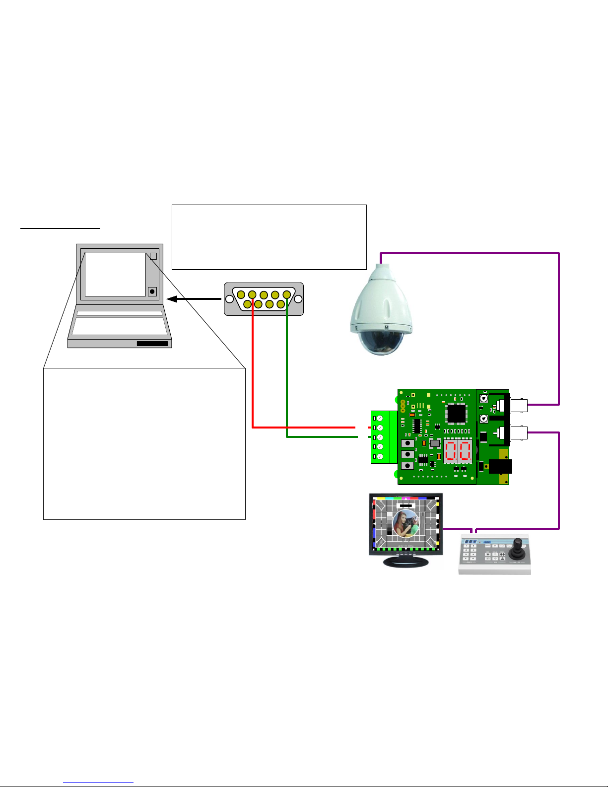
Rx10X in test mode
Fig 9.test mode
Rx100 TEST P2_V10 BBV
CHECKING EEPROM - WAIT
EE OK
P-0 T-0 Z-F-I- 1111
#1 ON
#1 OFF
P-0 TD0 Z-F-I-1111
P-0 TD1 Z-F-I-1111
P-0 T-1 Z-F-I- 1111
P-0 T-0 Z-F-I- 1111
PL0 T-0 Z-F-I-1111
PL2 T-0 Z-F-I-1111
Laptop computer
6 7 8 9
1 2 3 4 5
Solder Side
You will need to set up a HyperTerminal session on your laptop/PC.
With the following settings:
Bits per second: 38400
Data bits: 8
Parity: None
Stop bits: 1
Flow control: None
Once powered up the RX10X
It will display the following:
"Rx10X TEST V? (c) 2009 BBV"
P-0 T-0 Z-F-I- 1111 <- No Pan/Tilt/Zoom/Focus/Iris Alarms open
#1 ON <- #1 pressed
#1 OFF <- and released
#2 ON <- #2 pressed
#2 OFF <- and released
P-0 TD0 Z-F-I- 1111 <- Tilting Down at speed 0
P-0 TD1 Z-F-I- 1111 <- Tilting Down at speed 1
P-0 T-1 Z-F-I- 1111 <- stopped tilting
P-0 T-0 Z-F-I- 1111 <- No Pan/Tilt/Zoom/Focus/Iris Alarms open
PL0 T-0 Z-F-I- 1111 <- Panning Left at speed 0
PL2 T-0 Z-F-I- 1111 <- Panning Left at speed 2
BBV
R
X
L
O
HI
T
X
GND
www.bbvcctv.com
DATA
TxA/+
TxB/-
Gnd
20mA IN
20mA IN
LD2
BBV
PCB08009
GAIN
LIFT
Video from
Video to
12VDC
100mA
J2
J5
J6
J1
J3
J2
Controller
Dome
www.bbvcctv.com
BBV
PCB08009
SW1
SW2
SW3
1
2
3
J5
VR1
J3
Data out LED
IMPORTANT: To enable the Rx10X to go into it’s De-Bug
mode you must set it to:
Protocol - 0
Mode – 1
If mode 1 is not selected the Rx10X will revert to protocol
1 on reboot!
Page 18
Rx10X installation manual V3.02 Page 18
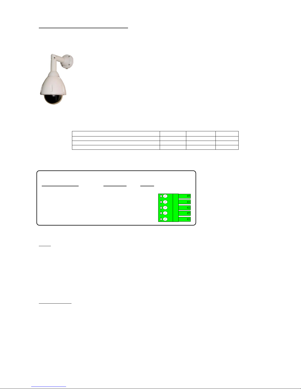
6.DOME SPECIFIC INFORMATION
Protocol 08
Dennard 2040, 2050, 2055 & 2060 dome.
The Rx10X can not be powered from the same
supply as the Dennard dome.
Variable speed Pan/Tilt.
Zoom/Focus, Auto focus
16 full scene presets (additional presets can be programmed using dome's menu)
2 preset patrols
Dennard 2040, 2050, 2055 & 2060
Tx40X
Tx1000
Tx1500
Dome User Menu
'#' 1
'#' WASH
1 ‘#’
Dome Supervisor Menu
'#' 2
'#' WIPE
2 ‘#’
Dome Service Menu
'#' 3
'#' AUTOPAN
3 ‘#’
The domes internal Sequence 001 can be started by pressing AUTOPAN. The sequence must be programmed
from the dome supervisor menu.
J6/5 DATA +
J6/4 BS Green
J6/3Gnd
BS Yellow
Gnd
J6/2
J6/1
7 Pin Plug
RS485
Rx10X
Dome Connection
Description
Pin 4
Pin 3
DATA
-
RS485 control of dome using the following connections:
The Dome must be addressed as 1 this is achieved by setting BLUE rotary sw. to 0 & YELLOW rotary sw. to 1
Notes:
Accessing the dome menus:
Press relevant key combination to display menu. To select highlighted menu item, perform a Goto preset 1 function as follows:
-Tx1500 press 1 followed be the preset key, Tx1000 Hold the PRESET key and tap the CAM1 key, Tx40X press the PRESET1
key.
The cursor can be moved using the standard pan/tilt keys or joystick. If the cursor direction is reversed, the pan and tilt cursor
directions can be reversed from the SUPERVISOR, USER OPTIONS, CURSOR CONTROL REVERSE menu.
Presets positions greater than 17 can be programmed using the dome's menu and can be built into dome sequences. Please
refer to dome manual for specific instructions regarding programming of sequences.
Options Function
Option 1 Enable datum mode goto preset 1 after 5 minutes if inactivity
Page 19
Rx10X installation manual V3.02 Page 19
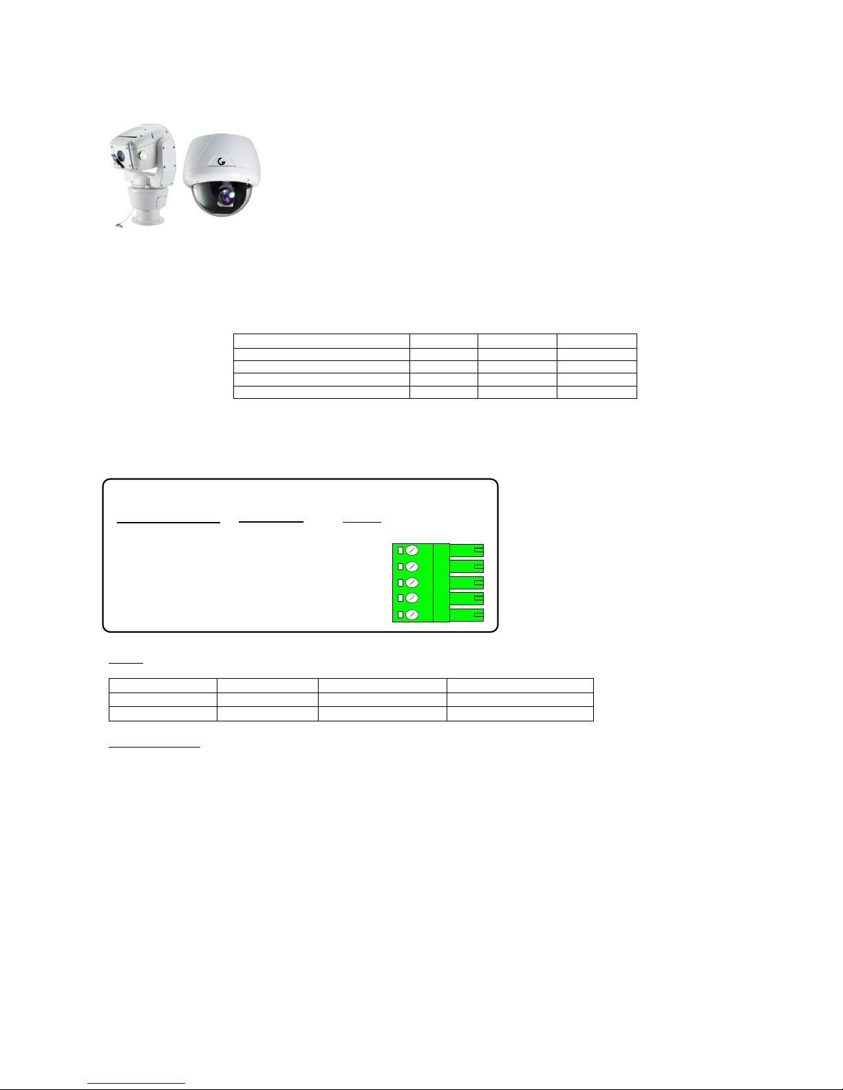
Protocol 14
GENIE RAPTOR, ASD276 & ASD376
PELCO D 2400
Variable speed manual Pan/Tilt & Zoom/Focus
16 Full scene presets.
2 preset patrols.
Pattern Tour playback using AUTOPAN
GENIE ASD276 & ASD376
Tx40X
Tx1000
Tx1500
Dome Menu (preset 95)
'#' 1
'#' WASH
1 ‘#’
Call SWING (preset 131)
'#' 2
'#' WIPE
2 ‘#’
Run SWING 1 (preset 141)
'#' 3
'#' AUTOPAN
3 ‘#’
Call GROUP1 (preset 151)
'#' 4
'#' LIGHTS
4 ‘#’
Pattern Tour 1 playback = press AUTOPAN (preset 131)
The dome and Rx10X are linked using RS485 for control and video for the camera signal.
J6/5 DATA +
J6/4
Tx-/A
J6/3
Tx-/B
Gnd
J6/2
J6/1
Rx10X
Dome Connection
Description
DATA
-
RS485 control of dome using the following connections:
Notes:
Dome Address
1 ON, 2-8 OFF
Address 1
1 ‘#’
Baud Rate
1-3 OFF
Pelco D, 2400
2 ‘#’
Termination
4 ON
RS485 Termination On
3 ‘#’
Options Function
Option 1 Enable datum mode goto preset 1 after 5 minutes if inactivity.
Option 4 Raptor Mode
Page 20
Rx10X installation manual V3.02 Page 20
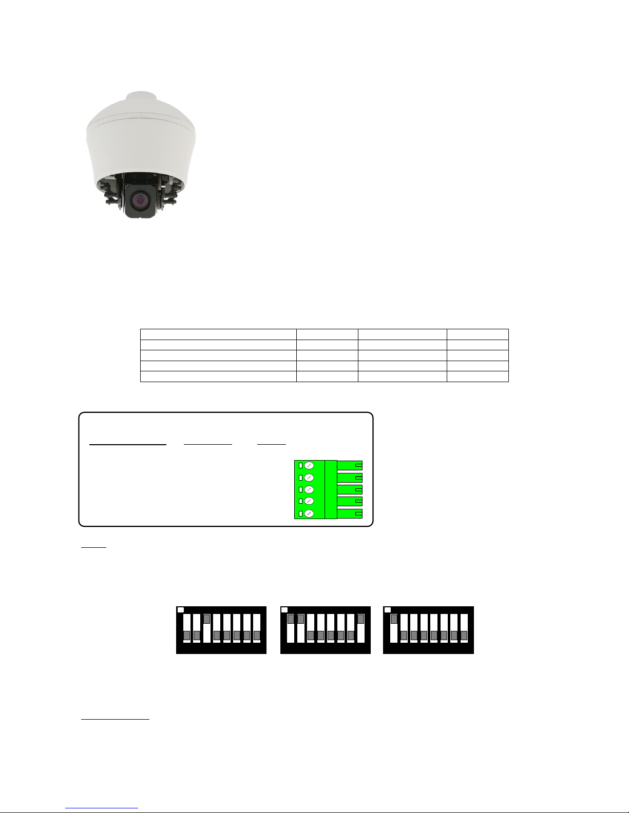
Protocol 15
Honeywell Acuix
Using VCL485
Variable speed Pan/Tilt.
Zoom/Focus, Auto focus following a Zoom In/Out.
16 Full scene presets.
2 preset patrols.
Slow preset tour. Started by pressing AUTOPAN
Program up to 16 privacy zones
Additional commands:
AUTOPAN: Pressing the AUTOPAN key will run the domes preset tour at slow speed between the patrol 1 preset position.
Iris Open/Close is menu Enter/Exit.
Honeywell Acuix Dome
Tx40X
Tx1000
Tx1500
DOME Menu
'#' 1
'#' WASH
1 ‘#’
(Toggle Mono/Colour)
'#' 2
'#' WIPE
2 ‘#’
(Auto Mono/Colour)
'#' 3
'#' AUTOPAN
3 ‘#’
Reset dome parameters
'#' 4
'#' LIGHTS
4 ‘#’
The dome and Rx10X are linked using RS485 for control and video for the camera signal.
J6/5 DATA +
J6/4
J6/3
Gnd
J6/2
J6/1
Rx10X
Dome Connection
Description
DATA
-
RS485 control of dome using the following connections:
RS485 Data +
RS485 Data -
Notes:
The dome address must be set at address 1 for all the cameras that are controlled using aRx10X. This is done in the Acuix by
setting SW4 to just 1 ON. Select VCL protocol by setting SW2 to 3 ON, rest OFF and SW3 to 1,2,8 ON, rest OFF. Check with
the dome manual if you have any doubts.
1 2 3 4 5 6 7 8
ON
SW4
SW2
1 2 3 4 5 6 7 8
ON
SW3
1 2 3 4 5 6 7 8
ON
If the slow preset tour is running, start patrol 1 & 2 is inhibited. A manual goto preset and lens control will stop the tour leaving
the AUTOPAN led on until the next manual pan command.
Options Function
Option 1 Enable datum mode goto preset 1 after 5 minutes if inactivity.
Page 21
Rx10X installation manual V3.02 Page 21
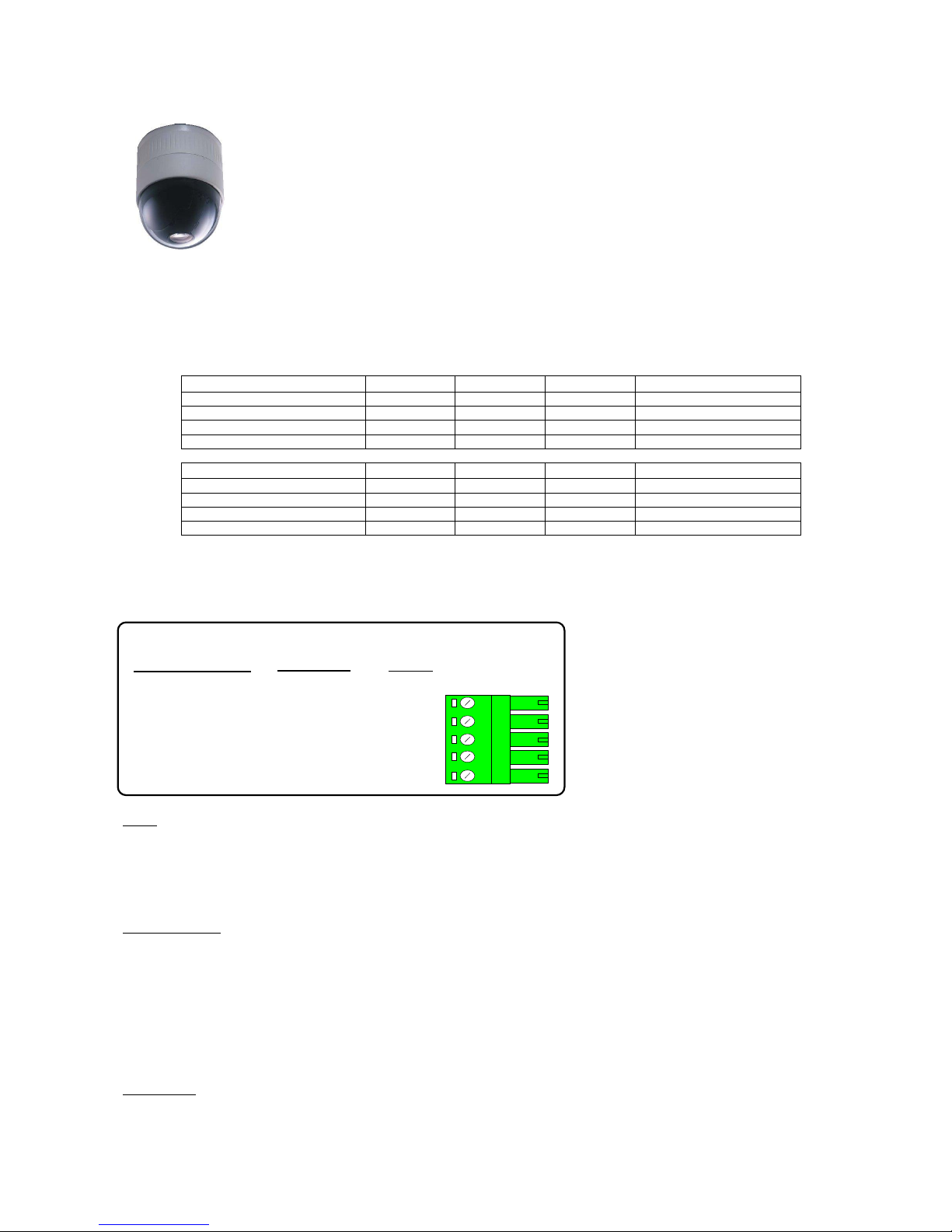
Protocol 11
JVC TK-C655B, 675B, TK-C675E,
TK-C675BE & 676
Variable speed Pan/Tilt.
Zoom/Focus, Auto focus can be enabled/ disabled from the dome menu.
16 Full scene presets.
2 preset patrols.
Slow patrol or dome autopan from controller AUTOPAN key
Vista up the coax Option 5
TK-C676
Tx40X
Tx1000
Tx1500
Vista Mux
OPEN MENU and BACK (Twice)
'#' 1
'#' WASH
1 ‘#’
Goto Preset 25 (x2)
SET
'#' 2
'#' WIPE
2 ‘#’
Goto Preset 26
Toggle ExDR
'#' 3
'#' AUTOPAN
3 ‘#’
Goto Preset 27
Cycle Mono Mode
'#' 4
'#' LIGHTS
4 ‘#’
Goto Preset 28
TK-C675B Option 4
TX40X
Tx1000
Tx1500
Vista Mux
SHUTTER SPEED
'#' 1
'#' WASH
1 ‘#’
Goto Preset 25 (x2)
BACKLIGHT AREAS
'#' 2
'#' WIPE
2 ‘#’
Goto Preset 26
AGC 0,12,20dB
'#' 3
'#' AUTOPAN
3 ‘#’
Goto Preset 27
DOME RESET
'#' 4
'#' LIGHTS
4 ‘#’
Goto Preset 28
A dome reset sets the camera as follows:Shutter to 1/50 sec, Backlight comp. off AGC to 20dB
The dome will display any change of Shutter Speed, Backlight or AGC for a short period.
J6/5 DATA +
J6/4
J6/3
Gnd
J6/2
J6/1
Rx10X
Dome Connection
Description
DATA
-
RS485 control of dome using the following connections:
C (Rx +)
D (Rx - )
Notes:
Camera switch settings:
MACHINE ID – set both rotary switches to ‘0’
8 way DIL switch, all OFF apart from 8 which should be ON to enable the RS485 termination, point-to-point, simplex.
On screen display of preset position, P01 - P16 or MANUAL during manual control. The on screen display can be enabled/disabled using dome
switch SW3, ON = Display off, OFF = Display on.
Options Function
Option 1: Enable datum mode goto preset 1 after 5 minutes if inactivity.
Option 2: Will perform a slow patrol between programmed presets when AUTOPAN pressed.
Option 3: on to allow the ExDR and MONO mode status to be displayed. Have this off if you are programming a dome camera title and do not
want to display the ExDR and MONO status.
Option 4: TK-C675B mode.
Option 5: Vista receive mode
DOME MENU
Pressing #1 twice will display the dome’s menu. The joystick is then used to navigate through the dome menu. #2 sends a SET command to the
dome and #1 twice whilst the menu is displayed sends a BACK command.
If the #1 command doesn’t work press a focus key before sending #1.
Pressing #1 FOUR times within 2 seconds will display the dome’s service menu.
Page 22
Rx10X installation manual V3.02 Page 22
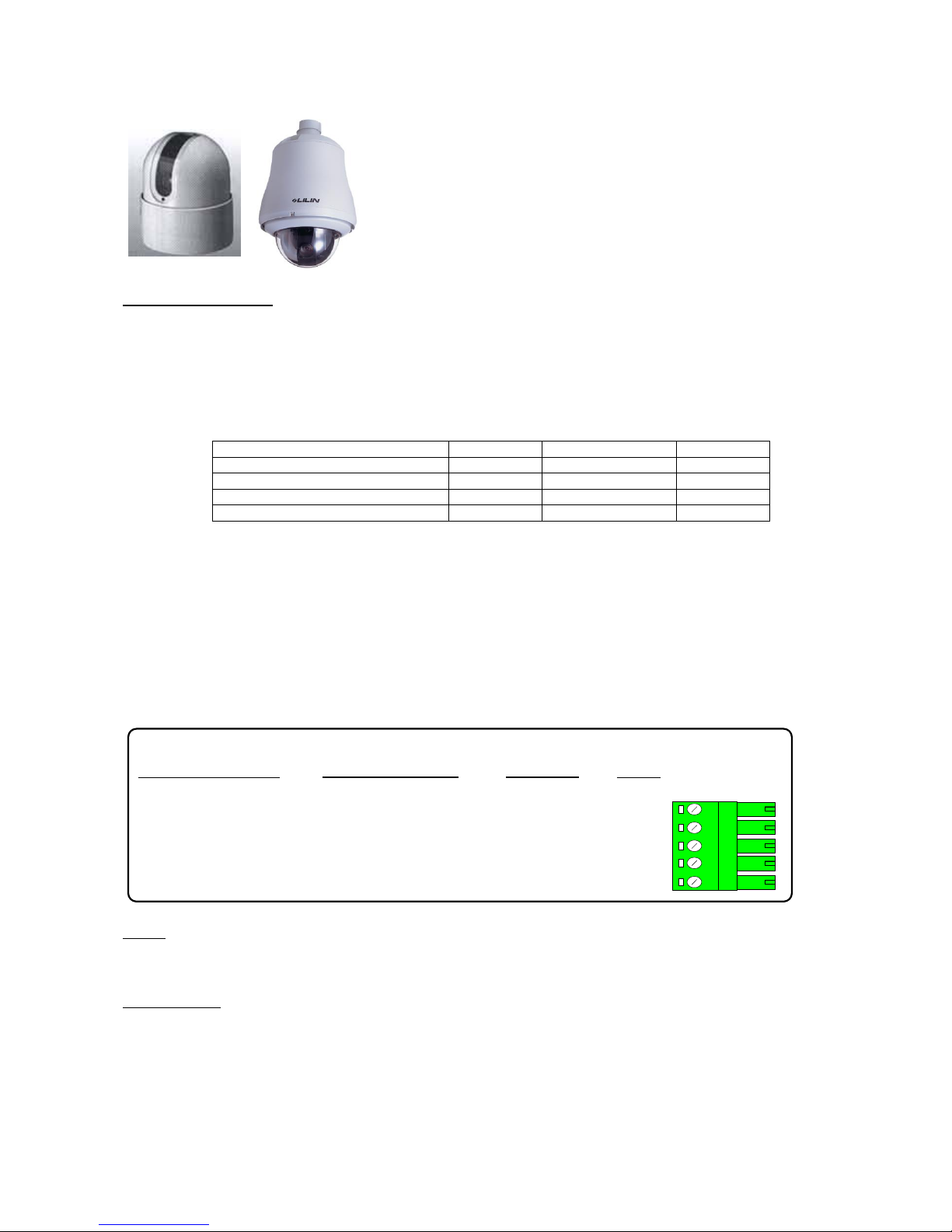
Protocol 16
Merit Li-Lin
PIH-717X/7000/7600/7625 series
Application Notes
Variable speed Pan/Tilt.
Zoom/Focus, Autofocus
16 full scene presets
2 preset patrols
4 alarm inputs driving to preset 1 - 4
Merit Li-Lin Dome
Tx40X
Tx1000
Tx1500
Dome Menu
'#' 1
'#' WASH
1 ‘#’
Enable Auto-Iris
'#' 2
'#' WIPE
2 ‘#’
Dome reset step 1
'#' 3
'#' AUTOPAN
3 ‘#’
Reset dome parameters
'#' 4
'#' LIGHTS
4 ‘#’
Procedure to program preset positions.
The procedure must be followed to program new preset positions and also to re-program existing positions.
The keystrokes shown below assume use of a Tx1500.
1) Select GOTO PRESET number to program eg 1 followed by PRESET
2) Move dome to new position using joystick and lens keys.
3) Select PROGRAM 1 PRESET to save new position eg PROGRAM 1 PRESET
To stop dome from running its own internal Autopan move joystick then press AUTOPAN.
DATA +
Gnd
Rx10X
PIH717(DB15) Dome
Description
DATA
-
RS485 control of dome using the following connections:
Pin 15
Pin 14
J6/5
J6/4
J6/3
J6/2
J6/1
PIH7000/7600 Dome
TXDI+
TXDI-
Notes:
Dome reset
All dome preset positions can be deleted using #3 followed by #4 within 1 second.
Options Function
Option 1: Enable datum mode goto preset 1 after 5 minutes if inactivity.
The default baud rate is 9600
Option 2: Force baud rate to 2400.
Option 3: Force baud rate to 4800.
Option 2 & 3: Force baud rate to 19200
Page 23
Rx10X installation manual V3.02 Page 23
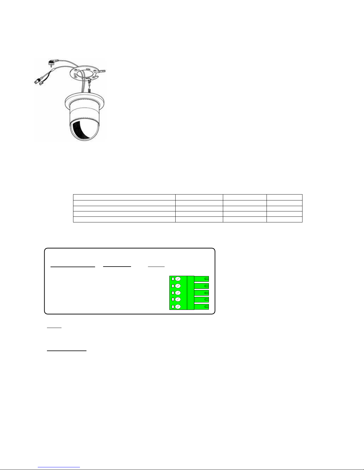
Protocol 09
Panasonic WV-CSR400 series.
WV-CSR600 series.
WV-CSR650 series.
Variable speed Pan/Tilt.
Zoom/Focus, Auto focus, Iris Open/Close (Auto focus with 600 & 650 series)
16 full scene presets (600 & 650 series dome)
2 preset patrols (600 & 650 series dome)
Autopan (600 & 650 series dome)
WV-CSR400 WV-CSR600 & WV-CSR650
Tx40X
Tx1000
Tx1500
ENTRY/EXIT dome menu
'#' 1
'#' WASH
1 ‘#’
SET (select menu item)
'#' 2
'#' WIPE
2 ‘#’
ESC (back to previous menu)
'#' 3
'#' AUTOPAN
3 ‘#’
SPECIAL2 (for special menus)
'#' 4
'#' LIGHTS
4 ‘#’
Autopan is started by selecting Autopan on the Transmitter. The Autopan stops can be programmed from within the dome
menu. Please refer to dome user manual for exact details.
J6/5 DATA +
J6/4
Green
J6/3
Yellow
Gnd
J6/2
J6/1
Rx10X
Dome Connection
Description
DATA
-
RS485 control of dome using the following connections:
Notes:
IMPORTANT: Dome settings: Select dome address 01. Communications must be 19200, N, 8, 1. If dome cannot be
controlled, see dome manual section to reset dome to factory default.
Options Function
Option 1 Enable datum mode goto preset 1 after 5 minutes if inactivity.
Page 24
Rx10X installation manual V3.02 Page 24
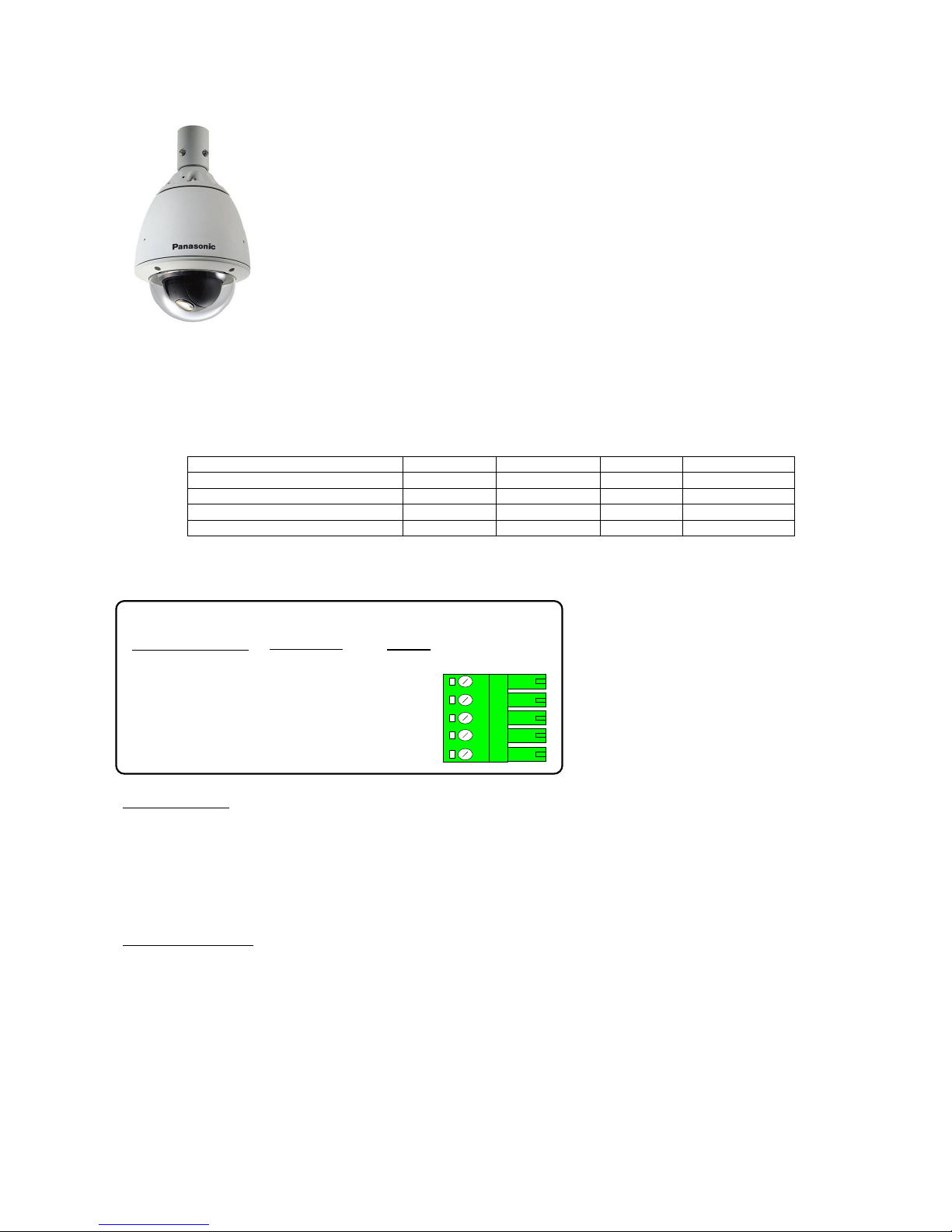
Protocol 10
Panasonic WV-CVS 850 & WV-CVS 960
Variable speed Pan/Tilt.
Zoom/Focus, Auto focus, Iris Open/Close (Hold for auto-iris)
16 full scene presets
2 preset patrols
Autopan/Patrol learn-play using autopan key
Vista up the coax Option 5
Panasonic WV-CS850 / 860 / 960
Tx40X
Tx1000
Tx1500
VistaMUX
ENTRY/EXIT dome menu
'#' 1
'#' WASH
1 ‘#’
Goto Preset 25
SET (select menu item)
'#' 2
'#' WIPE
2 ‘#’
Goto Preset 26
ESC (back to previous menu)
'#' 3
'#' AUTOPAN
3 ‘#’
Goto Preset 27
SPECIAL2 (for special menus)
'#' 4
'#' LIGHTS
4 ‘#’
Goto Preset 28
The dome’s internal PATROL can be LEARNED using the dome menu. Setting the AUTO PAN KEY to PATROL will allow the
patrol to be PLAYED by pressing AUTOPAN on the controller.
J6/5 DATA +
J6/4
Green
J6/3
Yellow
Gnd
J6/2
J6/1
Rx10X
Dome Connection
Description
DATA
-
RS485 control of dome using the following connections:
Options Functions
Option 1 Enable datum mode goto preset 1 after 5 minutes if inactivity.
Option 3 A dome RESET ALL command can be sent by selecting option 3 and sending 4 ’#’ twice within 5 seconds. This can
only be done when not within the menu.
Care must be used with this command as the dome is set to default and user settings are erased.
Option 5 Vista receive mode
Dome Switch settings:
The following procedure must be followed to ensure that the dome is set-up correctly for terminated 4 wire RS485 at 19200 Baud
and address 1. Remove the dome from its base before each step and reconnect to the base after changing the switches.
Step 1: Address switches 2, 4 and 5 ON
Step 2: Address switches 1, 3, 4 and 5 ON
Step 3: Address switches 1 and 8 ON. 4 Way switch 1 ON to select 4 wire, terminated RS485.
Page 25
Rx10X installation manual V3.02 Page 25
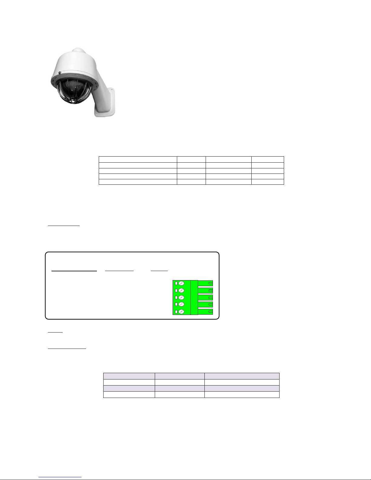
Protocol 02
Pelco Spectra & Esprit
(D-mode protocol 2400 N 8 1)
Variable speed Pan/Tilt.
Zoom/Focus, Auto focus
16 full scene presets
2 preset patrols
Dome Pattern definition and playback
Pelco protocol
Tx40X
Tx1000
Tx1500
Display dome menu (preset 95)
'#' 1
'#' WASH
1 ‘#’
Reset Head
'#' 2
'#' WIPE
2 ‘#’
Pattern define start
'#' 3
'#' AUTOPAN
3 ‘#’
Pattern define stop
'#' 4
'#' LIGHTS
4 ‘#’
To record a Pattern, direct the camera to the required starting position. Press 3 and then the '#' button, the dome will now record
pan/tilt and lens movement up to a time limit. To stop the recording, press 4 and then '#'. To play the recorded Pattern, press
the AUTOPAN key only. The dome will repeatedly run the Pattern until either the joystick is moved or the data delay is turned
on.
Menu access:
Use 1 ‘#’to display menu. Navigate using the joystick and IRIS OPEN to select.
RS485 control of dome: Data rate, 2400 Baud, No parity, 8 Data bits, 1 Stop bits
J6/5 DATA +
J6/4
Rx +
J6/3
Rx -
Gnd
J6/2
J6/1
Rx10X
Dome Connection
Description
DATA
-
RS485 control of dome using the following connections:
Notes:
Dome settings: Select dome address 1, D-MODE PROTOCOL and 2400, N, 8, 1.
Options Function
Option 1: enable datum mode goto preset 1 after 5 minutes if inactivity.
Option 2: is used to select the function that is used to drive the Esprit AUX outputs.
AUX Function
Option 2 OFF
Option 2 ON (Esprit AUX No)
LIGHTS 1 2
WIPER 2 1
WASHER 3 3
Option 3: is used to send a goto preset 95 or a save preset 95 when 1 # is sent to the Rx10X.
OFF = sends a save preset 95
ON = sends a goto preset 95
Option 4: is used to send a goto preset 64 to be used when controlling the COP Dome when 1 # is sent to the Rx10X this
supersedes Option 3:
Page 26
Rx10X installation manual V3.02 Page 26
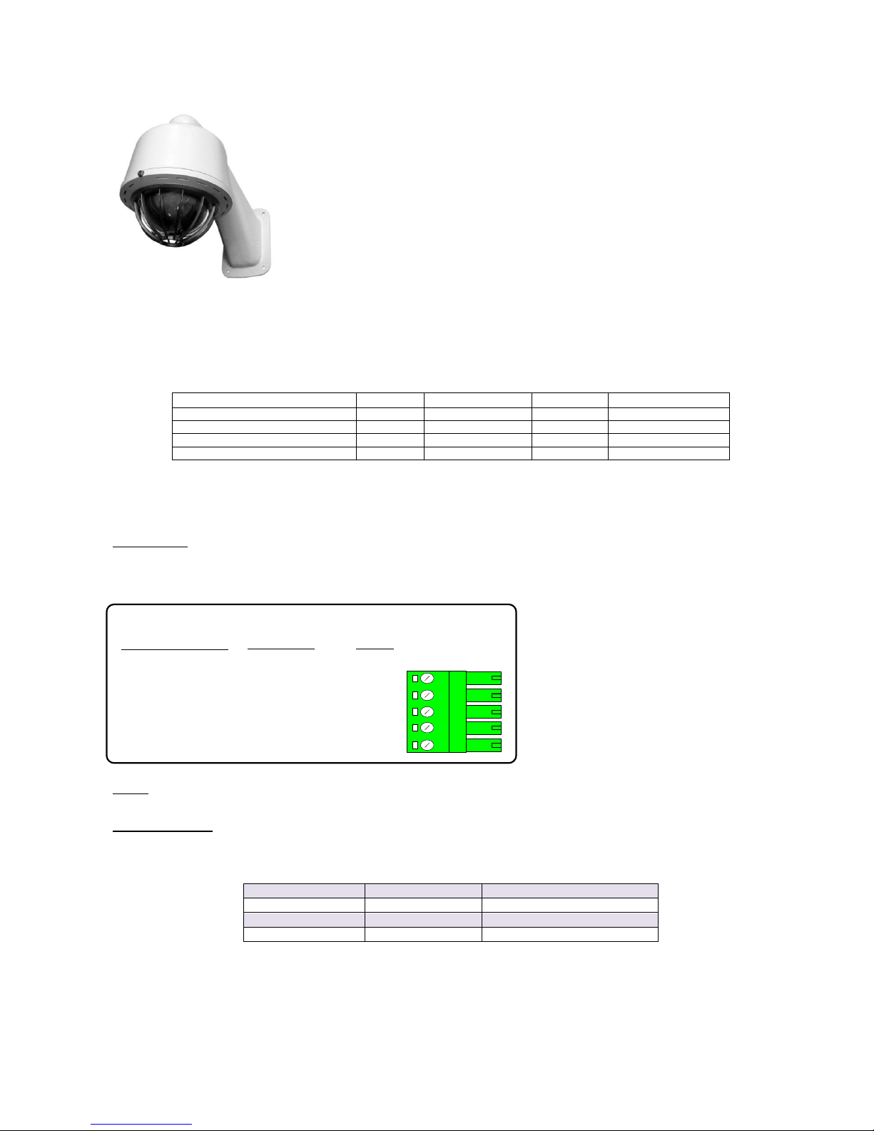
Protocol 01
Pelco Spectra & Esprit
(P-mode protocol 9600 N 8 1)
Variable speed Pan/Tilt.
Zoom/Focus, Auto focus
16 full scene presets
2 preset patrols
Dome Pattern definition and playback
Vista up the coax Option 5
Pelco protocol
Tx40X
Tx1000
Tx1500
Vista Mux
Display dome menu (preset 95)
'#' 1
'#' WASH
1 ‘#’
Goto Preset 25
Reset Head
'#' 2
'#' WIPE
2 ‘#’
Goto Preset 26
Pattern define start
'#' 3
'#' AUTOPAN
3 ‘#’
Goto Preset 27
Pattern define stop
'#' 4
'#' LIGHTS
4 ‘#’
Goto Preset 28
To record a Pattern, direct the camera to the required starting position. Press 3 and then the '#' button, the dome will now record
pan/tilt and lens movement up to a time limit. To stop the recording, press 4 and then '#'. To play the recorded Pattern, press
the AUTOPAN key only. The dome will repeatedly run the Pattern until either the joystick is moved or the data delay is turned
on.
Menu access:
Use1 ‘#’to display menu. Navigate using the joystick and IRIS OPEN to select.
RS485 control of dome. Data rate, 9600 Baud, No parity, 8 Data bits, 1 Stop bits
J6/5 DATA +
J6/4
Rx +
J6/3
Rx -
Gnd
J6/2
J6/1
Rx10x
Dome Connection
Description
DATA
-
RS485 control of dome using the following connections:
Notes:.
Dome settings: Select dome address 1, P-MODE PROTOCOL and 9600, N, 8, 1.
Options Function
Option 1 Enable datum mode goto preset 1 after 5 minutes if inactivity.
Option 2: is used to select the function that is used to drive the Esprit AUX outputs
AUX Function
Option 2 OFF
Option 2 ON (Esprit AUX No)
LIGHTS 1 2
WIPER 2 1
WASHER 3 3
Option 3: is used to send a goto preset 95 or a save preset 95 when 1 # is sent to the Rx10X.
OFF = sends a save preset 95
ON = sends a goto preset 95
Option 4: is used to send a goto preset 64 when 1 # is sent to the Rx10X. This is to be used when controlling the COP Dome
this supersedes Option 3:
Option 5 Vista receive mode
Page 27
Rx10X installation manual V3.02 Page 27
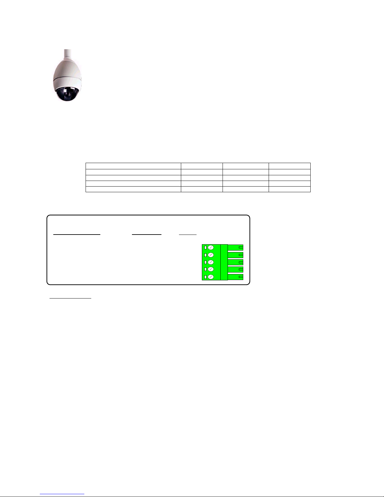
Protocol 13
Philips AutoDome including G3A and G3B
(RS232/RS485 control only, not Bi-Phase compatible)
Variable speed Pan/Tilt..
Zoom/Focus, Auto focus.
16 full scene presets.
2 preset patrols.
Dome AutoPlay record & playback.
Preshot title,
Zone title,
Menu Access
Philips protocol
Tx40X
Tx1000
Tx1500
Display Menu (Aux 46)
'#' 1
'#' WASH
1 ‘#’
Program Zone Title (Aux 63)
'#' 2
'#' WIPE
2 ‘#’
Record AutoPlay start/stop (Aux 100)
'#' 3
'#' AUTOPAN
3 ‘#’
RESET DOME! (Set 899)
'#' 4
'#' LIGHTS
4 ‘#’
RS232 & RS485 control of dome. Data rate, 9600 Baud, No parity, 8 Data bits, 1 Stop bits
J6/5 DATA +
J6/4 TxD
J6/3Gnd
RxD
Gnd
J6/2
J6/1
RS232
RS485
Rx10X
Dome Connection
Description
Not Used
RxD
DATA
-
RS485 control of dome using the following connections:
Options Function
Option 1 - Enable datum mode goto preset 1 after 5 minutes if inactivity.
Option 2 – Dome address, off = address 1, on = address 10,000 (special so all domes will respond)
Option 3 – Preset text title programming
OFF – preset title text is programmed following a save preset command by automatically issuing an aux (62) command.
ON – the preset text command is not sent and the existing text is retained.
Option 4 – special option for SWT providing Fixed speed pan/tilt (Added in V11 software)
The dome must be RS232 controllable. BI-PHASE domes cannot be controlled.
Dome settings: Select dome address #0 or #1. Communications must be 9600, N, 8, 1. The G3 Basic address is software
programmable; however as default the dome is addressed as #0. If the dome address is not #0 or #1 then the dome will require
reprogramming using a Philips controller or turn on option 2.
Page 28
Rx10X installation manual V3.02 Page 28
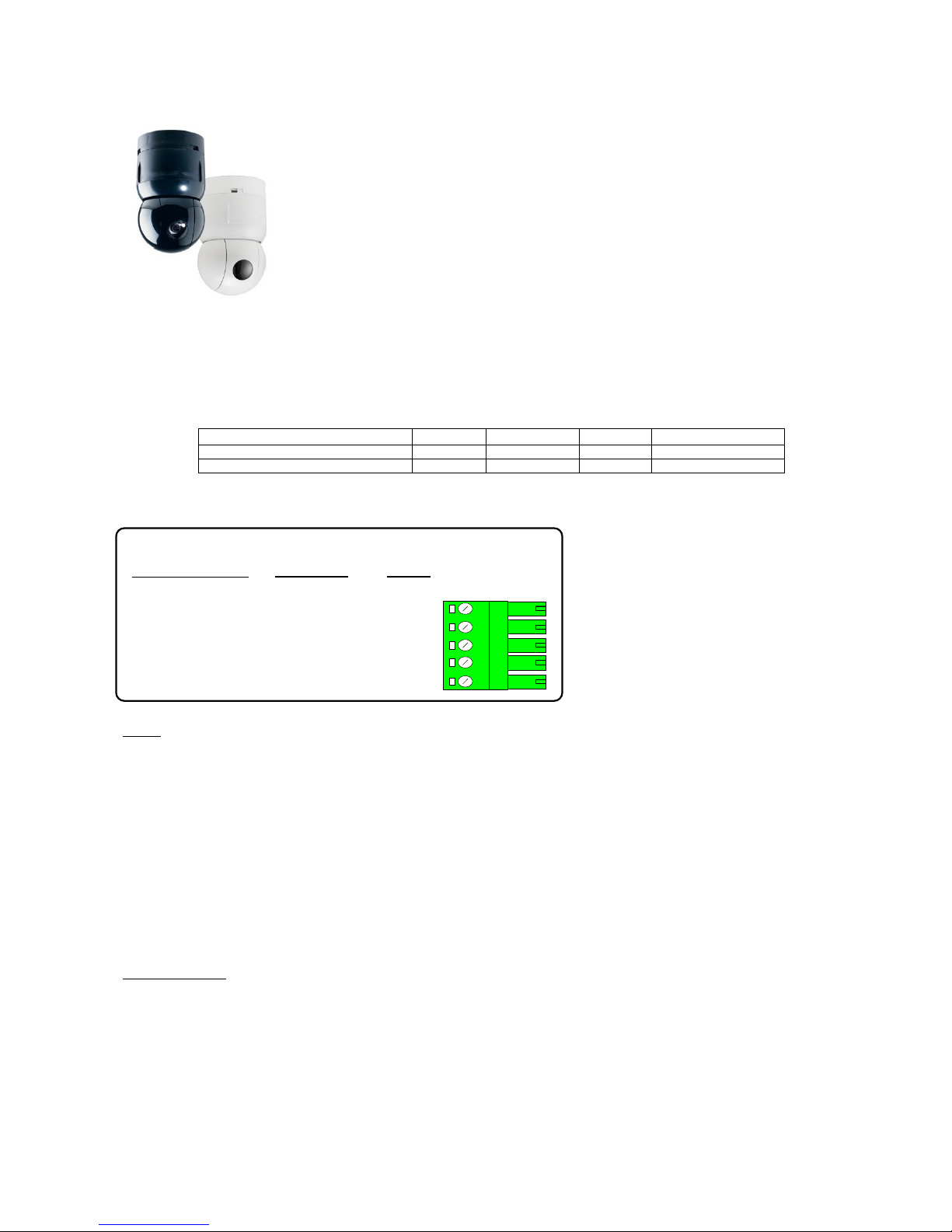
Protocol 07
Sensormatic Ultra Dome 5, 6, 7 & 8
Variable speed Pan/Tilt.
Zoom/Focus, Auto focus, Iris Open/Close
7 full scene presets
2 preset patrols
Pattern 1 define – play using Autopan key
Vista up the coax Option 5
Sensormatic Speeddome
Tx40X
Tx1000
Tx1500
Vista Mux
Dome menu
'#' 1
'#' WASH
1 ‘#’
Goto Preset 25
Start/Stop Pattern 1 Definition*
'#' 2
'#' WIPE
2 ‘#’
Goto Preset 26
RS485 control of dome 4800 Baud, No parity, 8 data bits, 2 stop bits.
J6/5 DATA +
J6/4
J6/3
Gnd
J6/2
J6/1
Rx10X
Dome Connection
Description
DATA
-
RS485 control of dome using the following connections:
RS422 IN +/Data In +
RS422 IN -/Data In -
Notes:
Accessing the dome menus.
Press either '#'1, '#'WASH ,1 '#' or Goto Preset 25 (when in Vista mode) to Enter Menu. Pan/Tilt/zoom/focus functions are then
used to navigate through menu structure. Please refer to individual dome manual for exact operation of menu.
Save User defined pattern
Press either '#'2, '#’WIPE, 2 '#' or Goto Preset 26 (when in Vista mode) to start recording user defined pattern. Then use Pan,
Tilt & zoom functions to make the pattern you require then press either '#'2, '#'WIPE , 2 '#' or Goto Preset 26 (when in Vista
mode) to stop the recording of the user defined pattern.
IMPORTANT:
Dome settings: Select dome address 01 or 001.
Communications must be 4800, N, 8, 2 – RS422, NOT SensorNet.
The interface software is based on 1997 protocol and has been tested with Ultradome IV, Ultradome VI and original Speeddome.
Options Function
Option 1 Enable datum mode goto preset 1 after 5 minutes if inactivity.
Option 1 + 2 both on to start preset patrol after 5 minutes if inactivity.
Option 5 Vista receive mode
Page 29
Rx10X installation manual V3.02 Page 29
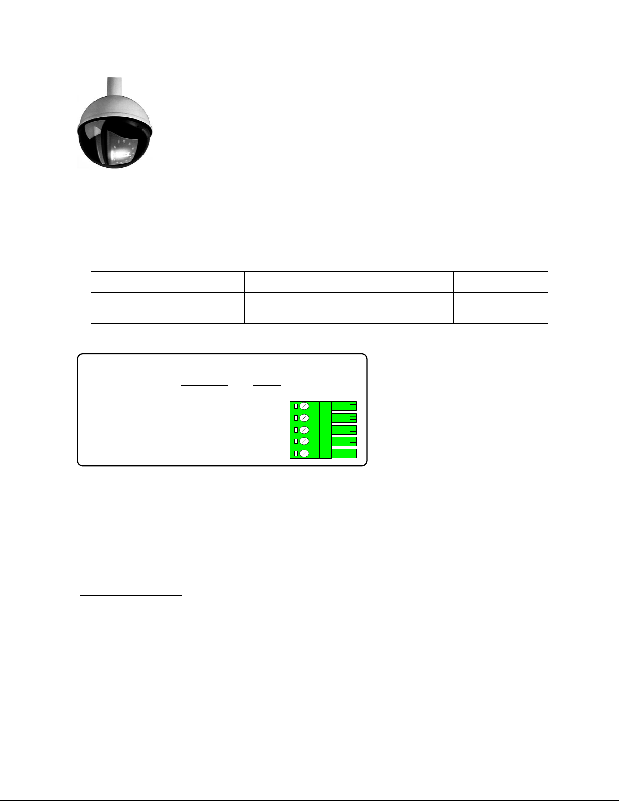
Protocol 03
VCL Microsphere/Orbiter range.
Variable speed Pan/Tilt.
Zoom/Focus, Auto focus following a Zoom In/Out.
16 Full scene presets.
2 preset patrols.
Slow preset tour. Started by pressing AUTOPAN
Program up to 16 privacy zones
Vista up the coax Option 5
Additional commands:
AUTOPAN: Pressing the AUTOPAN key will run the domes preset tour at slow speed between the patrol 1 preset position.
VCL Dome
Tx40X
Tx1000
Tx1500
Vista Mux
180 degree pan flip
'#' 1
'#' WASH
1 ‘#’
Goto Preset 25
Privacy SET (Toggle Mono/Colour)
'#' 2
'#' WIPE
2 ‘#’
Goto Preset 26
Privacy CLEAR (Auto Mono/Colour)
'#' 3
'#' AUTOPAN
3 ‘#’
Goto Preset 27
Reset dome parameters
'#' 4
'#' LIGHTS
4 ‘#’
Goto Preset 28
The dome and Rx10X are linked using RS485 for control and video for the camera signal.
J6/5 DATA +
J6/4
J6/3
Gnd
J6/2
J6/1
Rx10X
Dome Connection
Description
DATA
-
RS485 control of dome using the following connections:
D +
D -
Notes:
The dome address must be set at 1 for all the cameras that are controlled using a RX10X. With an Orbiter Gold, set the address
to 1 with all switches of DILSW2 ON. Select VCL protocol with all switches of DILSW1 OFF. Check with the dome manual if you
have any doubts.
If the slow preset tour is running, start patrol 1 & 2 is inhibited. A manual goto preset and lens control will stop the tour leaving
the AUTOPAN led on until the next manual pan command.
Options Function
Option 1 Enable datum mode goto preset 1 after 5 minutes if inactivity.
Privacy zone programming.
Option 2 must be ON to allow programming of privacy zones.
– The keystrokes shown assume use of a Tx1500. Use the keystroke shown above if using another controller.
Option 5 Vistareceive mode
Programming a zone
The Rx10X can be used to program 16 privacy zones, 100 – 115. The same procedure that is used to program a preset position
is used to program or clear a privacy zone. To instruct the Rx10X to program privacy zoon , zoom until the object you wish to
mask fill the entire screen then press 2# followed by program preset 1 – 16. The screen will then go blank showing that the
privacy zone has been set.
Clearing a zone
To clear/delete privacy zone press 3# followed by program preset 1 – 16. The relevant privacy zone will then be disabled.
Mono/Colour switching
If manual mono/colour switching is required then option 2 must be OFF. This will disable the privacy zone set/clear features.
Page 30
Rx10X installation manual V3.02 Page 30
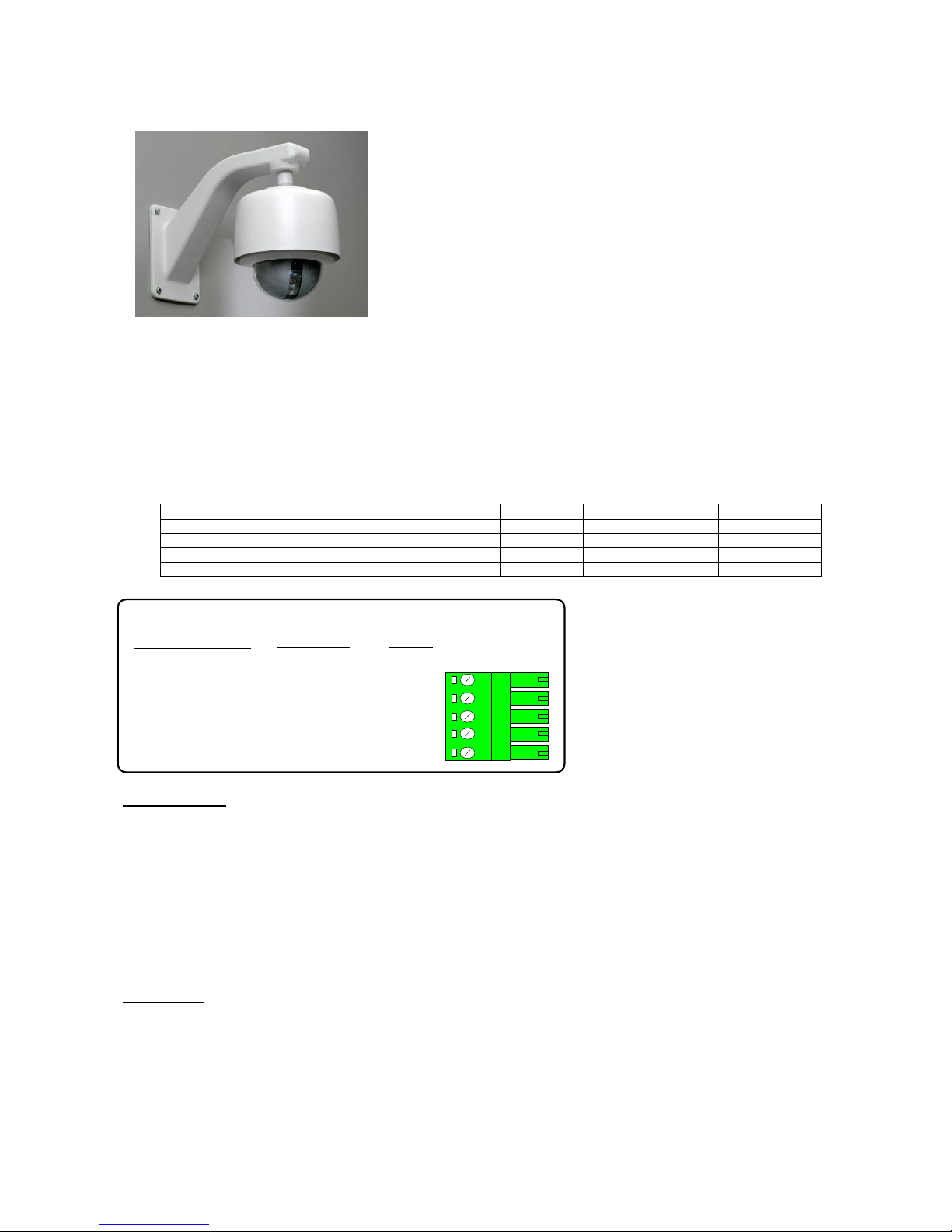
Protocol 04
Surveyor Range, SVFT & S10.
Variable speed Pan/Tilt.
Zoom/Focus, Auto focus with manual override.
16 full scene presets (additional presets available using dome's menu)
2 preset patrols
Additional commands:
RUN TOUR 80.
Pressing the AUTOPAN key will start the dome's Tour 80. The tour is programmable using the dome's menu and allows a
complex preset patrol, autopan or auto tour to be programmed. Refer to the dome programming manual for exact details.
Vicon Dome
Tx40X
Tx1000
Tx1500
*Dome Menu – Store preset 94 (also AP once in menu)
'#' 1
'#' WASH
1 ‘#’
AI (used as escape in menu)
'#' 2
'#' WIPE
2 ‘#’
AUX1
'#' 3
'#' AUTOPAN
3 ‘#’
AUX2
'#' 4
'#' LIGHTS
4 ‘#’
J6/5 DATA +
J6/4
J6/3
Gnd
J6/2
J6/1
Rx10X
Dome Connection
Description
DATA
-
RS485 control of dome using the following connections:
COMM IN +
COMM IN -
Options Function
Option 1 Enable datum mode goto preset 1 after 5 minutes if inactivity.
On first entering the menu, the dome may autopan and/or access the pan/tilt menu. This is acceptable and simply pressing the
AI function will allow the main menu to be displayed.
If the dome's tour 80 is running, start patrol 1 & 2 is inhibited. Accessing the dome menu.
Press 1# to display menu. Use pan/tilt keys or joystick to move cursor. 1 ‘#' now acts as the AP key and2'#' as the AI key as
described on screen. 3 ‘#’ and4 ‘#’ are used as AUX1 and AUX2 during menu programming.
Presets positions greater than 17 can be programmed using the dome's menu. These can be built into Tour 80 which is started
by pressing the AUTOPAN key. Please refer to dome manual for specific instructions.
IMPORTANT:
Dome switch settings for the Surveyor: S1 selects dome address, please set to address 1, SW1/1=ON others OFF.
S2 is used to select control method and video standard. Set to Simplex data S2/3 = ON & VPS with S2/2=OFF. (SW2 1, 5, 6,
7& 8= OFF)
For other versions of dome that do not support auto baud rate detect ensure that baud set for 9600.
Please check Vicon manual to confirm switch settings.
Page 31
Rx10X installation manual V3.02 Page 31
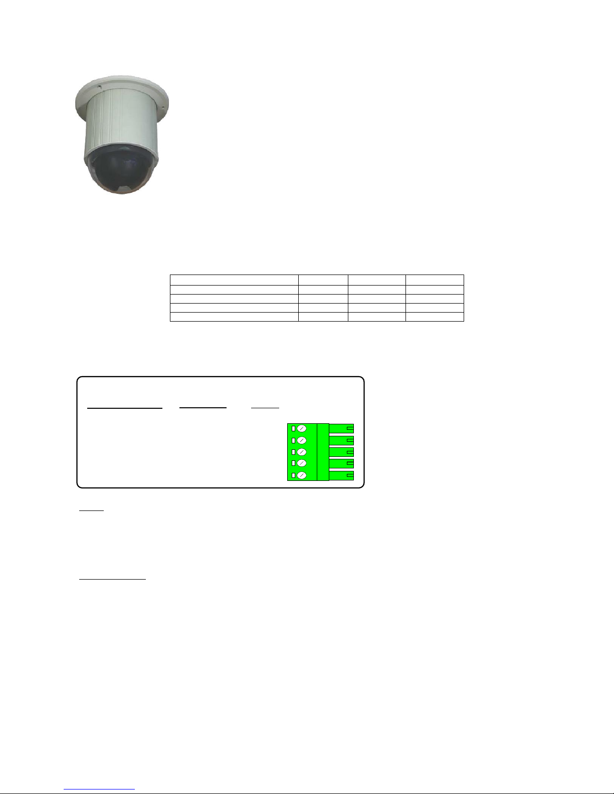
Protocol 05
VideconVCP451&VHCD 860
Variable speed Pan/Tilt.
16 Full scene presets.
2 Rx10X preset patrols.
Pattern Tour 1 learn and playback using AUTOPAN
Privacy zone support
IR Filter CUT using LIGHTS. Lights ON = FILTER OFF, Lights OFF = FILTER ON
Videcon Dome
Tx40X
Tx1000
Tx1500
Display MENU
'#' 1
'#' WASH
1 ‘#’
Display Privacy Menu
'#' 2
'#' WIPE
2 ‘#’
Record Pattern Tour 1
'#' 3
'#' AUTOPAN
3 ‘#’
Stop Recording
'#' 4
'#' LIGHTS
4 ‘#’
Pattern Tour 1 playback = press AUTOPAN
The dome and Rx10X are linked using RS485 for control and video for the camera signal.
J6/5 DATA +
J6/4
J6/3
Gnd
J6/2
J6/1
Rx10X
Dome Connection
Description
DATA
-
RS485 control of dome using the following connections:
D +
D -
Notes:
The dome switches must be as follows to select Pelco P, 9600 baud and address 1.
SW1, 1 ON, 2-7 OFF. SW2, 1 & 2 ON, Protocol switch 1-4 all OFF
When navigating the dome’s menu or privacy setup use the joystick and IRIS OPEN and CLOSE.
The dome manual has detailed information on the menu structure and privacy setting.
Options Function
Option 1 Enable datum mode goto preset 1 after 5 minutes if inactivity.
Option 2 ON to allow LIGHTS to switch the IR CUT filter ON/OFF when used with a day/night dome.
Page 32
Rx10X installation manual V3.02 Page 32
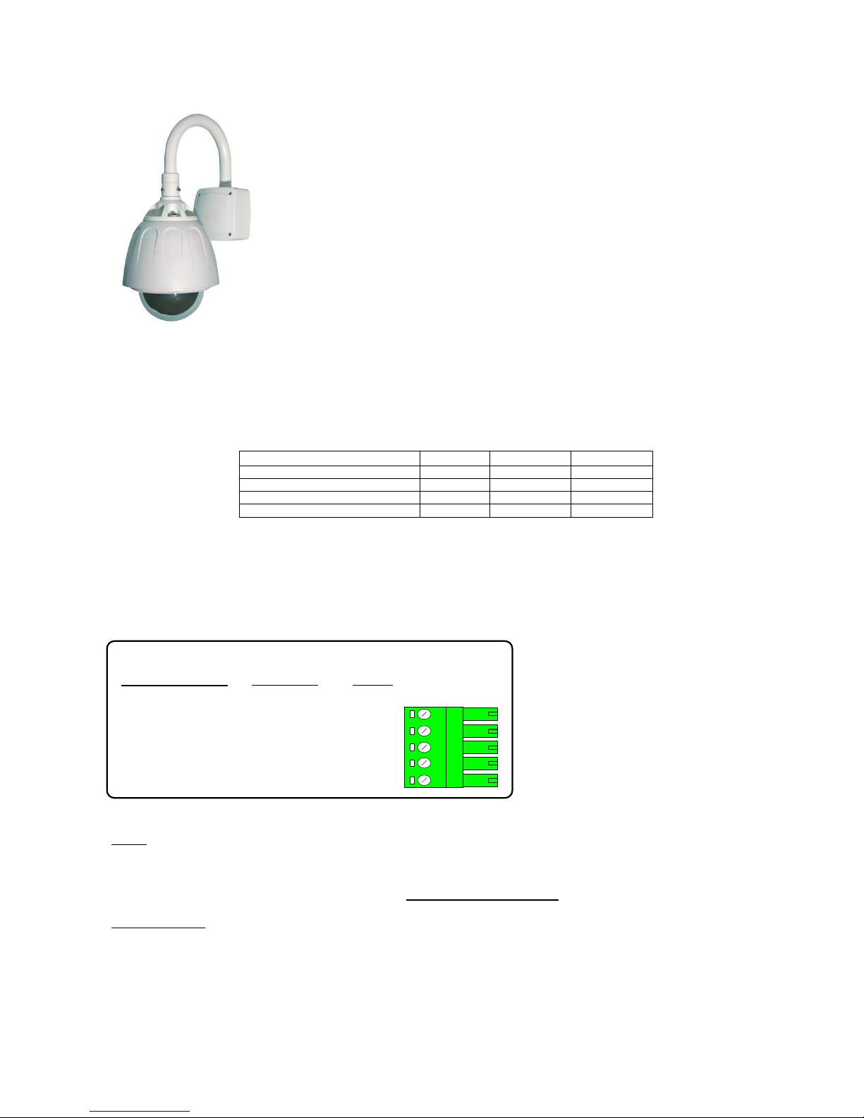
Protocol 06
VIDECONVHSD 870
PELCO D 2400 or 9600 BAUD
Variable speed manual Pan/Tilt & Zoom/Focus
16 Full scene presets.
2 preset patrols.
Pattern Tour playback using AUTOPAN
Privacy zone support from within dome Menu
Videcon VHSD 870 Dome
Tx40X
Tx1000
Tx1500
DOME Menu (preset 95)
'#' 1
'#' WASH
1 ‘#’
Call SWING (preset 141)
'#' 2
'#' WIPE
2 ‘#’
Call GROUP1 (preset 151)
'#' 3
'#' AUTOPAN
3 ‘#’
Call GROUP2 (preset 152)
'#' 4
'#' LIGHTS
4 ‘#’
When navigating the dome’s menu or privacy setup use the joystick and FOCUS NEAR and FOCUS FAR. The dome
manual has detailed information on the menu structure and privacy setting.
Pattern Tour 1 playback = press AUTOPAN (preset 131)
The dome and Rx10X are linked using RS485 for control and video for the camera signal.
J6/5 DATA +
J6/4
J6/3
Gnd
J6/2
J6/1
Rx10X
Dome Connection
Description
DATA
-
RS485 control of dome using the following connections:
Tx-/A
Tx-/B
Notes:
The dome switches must be as follows:
Dome Address: 1 ON, 2-8 OFF (Address 1)
Switches 1&2 on the six bank configure the Protocol/Baud 3 – 6 should be left as Factory.
Options Function
Option 1 Enable datum mode goto preset 1 after 5 minutes if inactivity.
Option 2 Selection of baud rate.
OFF Pelco D, 2400 baud Protocol and Baud: 1 – 5 OFF, 6 ON
ON Pelco D, 9600 baud Protocol and Baud: 1 & 6 ON 2 – 5 OFF
Page 33
Rx10X installation manual V3.02 Page 33
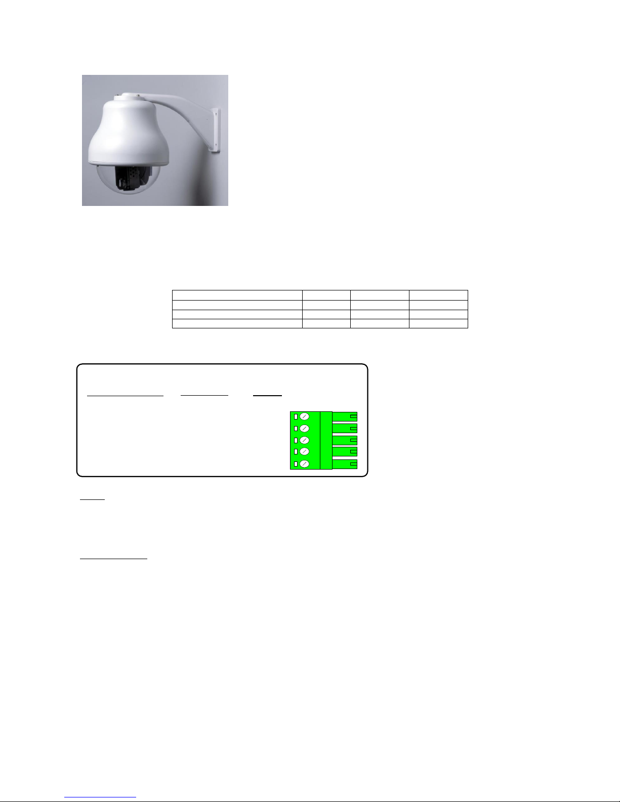
Protocol 12
Vista Power Dome
Variable speed Pan/Tilt.
Zoom/Focus, Focus/Iris Override returning to auto after Zoom In/Out.
16 Full scene presets.
2 preset patrols. (PATROL1 = Rx10X patrol and PATROL 2 = dome’s TOUR)
Learned tour playback using AUTOPAN key.
Program up to 16 privacy zones
Vista Power Dome
Tx40X
Tx1000
Tx1500
Display MENU
'#' 1
'#' WASH
1 ‘#’
ENTER in MENU
'#' 2
'#' WIPE
2 ‘#’
ESC in MENU
'#' 3
'#' AUTOPAN
3 ‘#’
The dome and Rx10X are linked using RS485 for control and video for the camera signal.
J6/5 DATA +
J6/4
J6/3
Gnd
J6/2
J6/1
Rx10X
Dome Connection
Description
DATA
-
RS485 control of dome using the following connections:
RS485 A +
RS485 B -
Notes:
The dome address must be set at 1 for all the cameras that are controlled using a Rx10X. Check with the dome manual
to enable the correct setup of the dome.
If the learned tour playback is running, start patrol 1 is inhibited.
Options Function
Option 1 Enable datum mode goto preset 1 after 5 minutes of inactivity.
Option 1 + 2 both on to start dome TOUR2 instead of goto Preset 1 after 5 minutes if inactivity.
Option 3 reverses the pan direction.
The dome’s TOUR2 must be programmed from within the domes menu. Please refer to the dome manual for details.
Page 34

Rx10X installation manual V3.02 Page 34
7. TROUBLESHOOTING
Symptom: No video from interface.
Possible causes:
∙ Camera is not powered or not connected to ‘Video from camera’ BNC on interface.
∙ Check power and cabling.
∙ Interface is not powered.
∙ Check power.
∙ Video out not connected to ‘Video to controller’ BNC on interface.
∙ Check cabling.
If the after following the above check list video still not present then remove both BNCs from
the interface and connect together using a female/female barrel connector to check video path
from camera to control point.
Symptom: No camera control but data out LED lights when the joystick is moved.
Possible causes:
∙ Dome data cable is not connected correctly.
∙ Check cabling, most commonly due to data cables swapped.
∙ Dome configuration switches if fitted not set correctly.
∙ Check configuration.
Symptom: Interface not seeing Telemetry signal.
*NB Not all transmitters provide a constant telemetry signal, therefore seeing error 9.1 until
telemetry is sent is normal. This error will be seen if using a CTI/1, Tx1500 and will also occur
if the camera is not selected on a Tx1000.
Possible causes:
∙ Check that telemetry is present on video cable using either oscilloscope or adjust v. hold on
monitor to view frame blanking period and check for black/white band. If missing, power
down/up the transmitter. Should this fail, swap video between working and non-working
channels.
∙ Earth loops can interrupt telemetry operation if sufficiently severe.
If hum bars are apparent, fit isolation transformer to coaxial cable.
Check the two red 7 segment LED displays mounted on the top PCB on interface see page 10.
If the problem persists having followed the above steps, technical assistance can be received
from Building Block Video. Tel: +44 (0)1323 444600
Page 35

Rx10X installation manual V3.02 Page 35
Page 36
Rx10X installation manual V3.02 Page 36
Extend your BBV Warranty from 12 months to 3 years
As of the 1st September 2008 BBV have offered our
customers the opportunity to extend the standard 12 month
warranty to 3 years.
You must register for the extended warranty within 12 months
of the date of manufacture.
How to register for the 3 year warranty
Registering for the new, longer 3 year warranty term is quick
and easy.
Either:
Complete the warranty application card that comes in the box
with your BBV product, and return it FREEPOST to BBV:
VAT Reg. No. 621758439 Registered in England No. 2852921 Registered office: 17 Apex Park Diplocks Way Hailsham East Sussex UK BN27 3JU
If this card is returned with the serial number of the product and the Installation company
details BBV will extend the warranty period from 12 Months to 36 Months.
I do not require any other further product information,
BBV 3 Year Warranty
Please could you send me information
especially on:
Rx100s
Rx45x & Rx55x
FBM Video Matrices
Tx1500 Video Matrices
Starcard & Starcard Converters
BBV Quad
Pick A Point
Please refer to WWW.BBVCCTV.COM for terms, conditions & exclusions
Contact Name.
Company Name.
Phone Number.
Site Name.
Address 1.
Address 2.
Address 3.
e-mail address.
Post Code.
Do you read.
Number of Units, Start Serial No. Final Serial No.
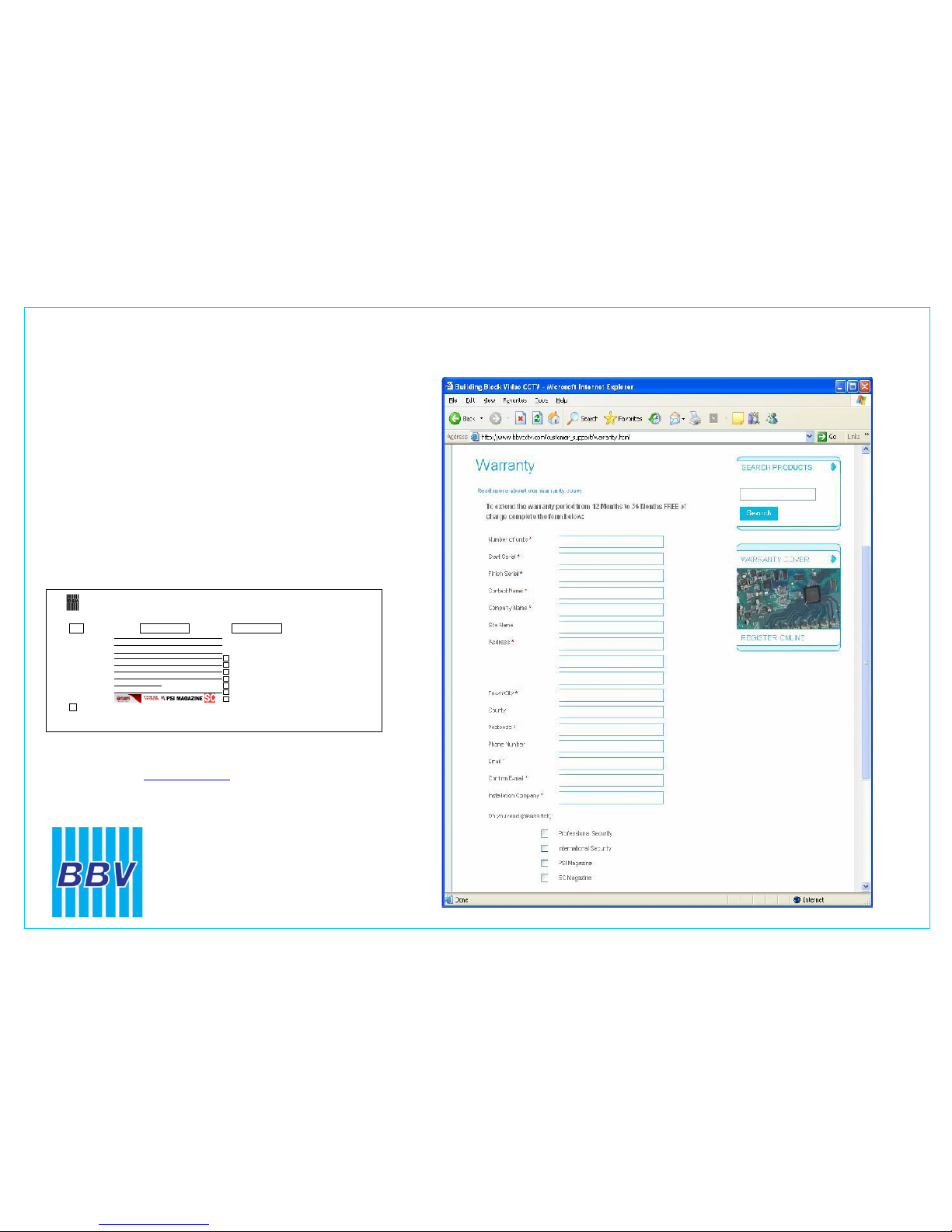
Or alternatively:
Register online at: www.bbvcctv.com
Simply enter your details on the ‘Warranty Cover’ page.
Building Block Video Ltd
Tel: + 44 (0) 1323 842727
Fax: + 44 (0) 1323 842728
Support: + 44 (0) 1323 444600
www.bbvcctv.com
 Loading...