

Page 1
Building Block Video Ltd.,
17 Apex Park,
Diplocks Industrial Estate,
Hailsham, East Sussex, BN27 3JU UK.
Tel: +44(0)1323 842727
Fax: +44(0)1323 842728
Support: +44(0)1323 444600
www.bbvcctv.com
Models covered
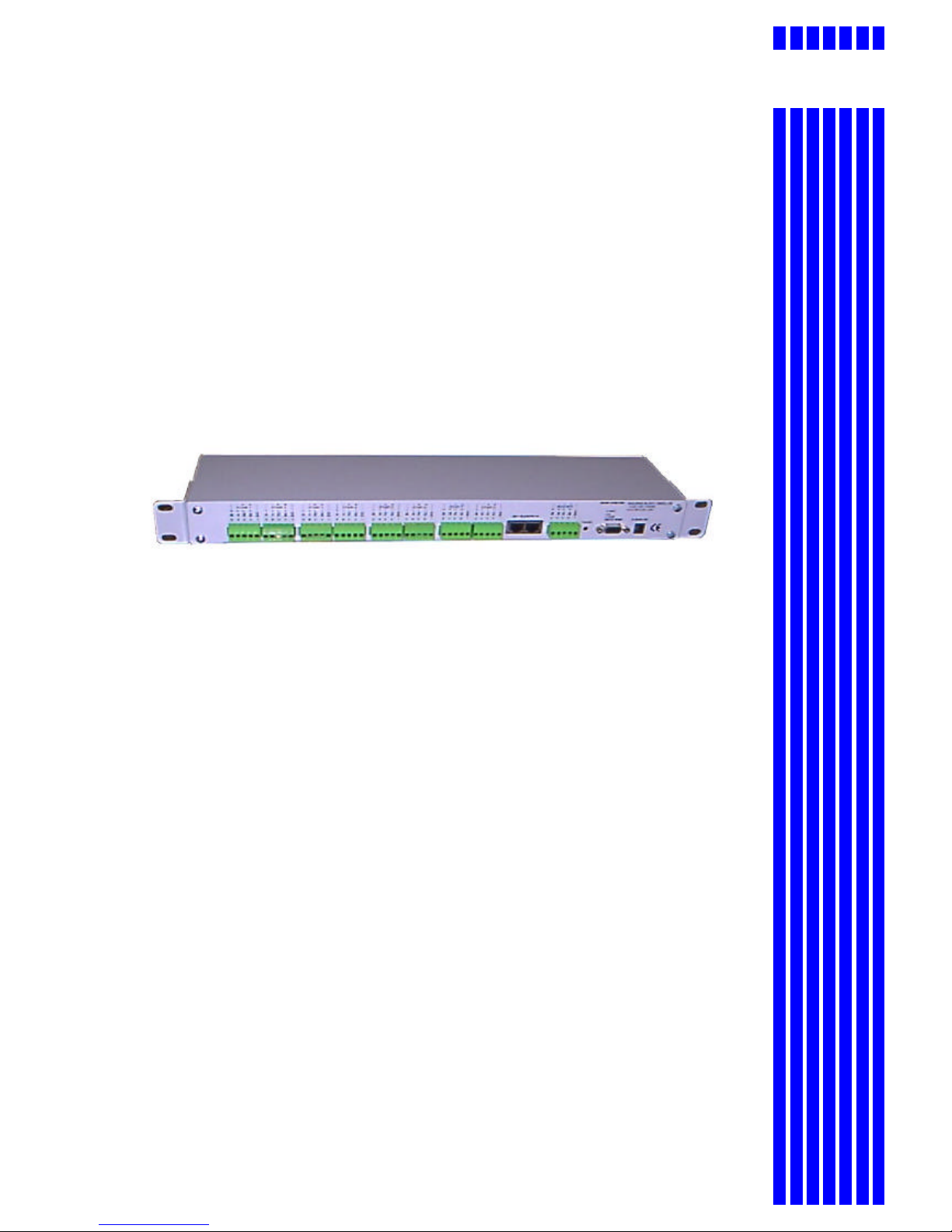
RS485 StarCard including optional
Telemetry Protocol Converter
This manual covers software version CONV1_V14. Refer to addendum if using different software.
BBV RX450/550, CBC SMD20/Star MD2000/Sanyo VCC9200P, Chugai/Ganz ZC-S122/123,
Dennard 2050, JVC 676, Mark Mercer, Molynx 250/260, Panasonic CS850/860, Pelco P , Pelco D,
360 Vision, VCL, Vicon Surveyor, Vista PowerDome, Samsung 641/643 dome 421P camera, Meyertech
ZVR510 VICTA protocol.
Installation
Guide
BBVBBV
Page 2

RS485 Star Card Manual V14 4Feb04.doc Page 2/29
1. PRE-INSTALLATION CHECKS AND SAFETY PROCEDURES
UNPACKING
Check Packaging - Upon taking delivery of the unit, inspect the packaging for signs of
damage. If damage has occurred, advise the carriers and/or the suppliers immediately.
Check Contents - Upon taking delivery of the unit, unpack the receiver carefully and
check that all the items are present and correct. If any items are missing or damaged,
contact your equipment dealer.
Retain Packaging - The shipping carton is the safest container in which to transport the
unit. Retain undamaged packaging for possible future use.
IMPORTANT SAFETY PRECAUTIONS
Read Instructions - All relevant safety, installation and operating instructions should be
read before attempting to install, connect or operate the unit.
Retain Instructions - All safety, installation and operating instructions should be retained
for future reference.
Heed Warnings - All warnings on the unit and in any relevant safety, installation or
operating instructions should be adhered to.
Cleaning - Unplug the unit from the power outlet before cleaning. Do not use liquid
cleaners or aerosol cleaners. Use a damp cloth for cleaning.
Attachments - Do not use attachments not recommended by the product manufacturer
as they may cause hazards.
Water and Moisture - Do not expose the internal electronics of this unit to water or
dampness; for example, in an unprotected outdoor installation, or in any area classified
as a wet location. The unit as supplied conforms to ingress protection rating IP 67. This
rating will be affected by any holes made in the enclosure. Cable entry points should be
protected by the use of suitably rated glands and/or flexible conduit. It is not necessary
to make further holes in the enclosure for mounting purposes, as mounting holes are
provided at the corners of the enclosure outboard of the seal between enclosure and lid.
Accessories - Do not attach this unit to an unstable stand, bracket or mount. The unit
may fall, causing serious injury to a person and serious damage to the unit.
Power Sources - This unit should be operated only from the type of power source
indicated on the manufacturer’s label. If you are not sure of the type of power supply you
intend to use, consult your equipment dealer or local power company. For units intended
to operate from battery power or other sources, refer to operating instructions.
Page 3

RS485 Star Card Manual V14 4Feb04.doc Page 3/29
Overloading - Do not overload outlets and extension cords, as this can result in fire or
electric shock.
Object and Liquid Entry - Never push objects of any kind into the unit, as they may
touch dangerous voltage points or short out parts that could result in fire or electric
shock. Never spill liquid of any kind on or inside the unit.
Servicing - Servicing of the unit should only be undertaken by qualified service
personnel, as opening or removing covers may expose you to dangerous voltages or
other hazards.
Damage Requiring Service - Servicing by qualified personnel should be carried out
under the following conditions:
(a) When the power-supply cord or plug is damaged;
(b) If liquid has been spilled, or objects have fallen into, the unit;
(c) If the internal electronics of the unit have been exposed to rain or water;
(d) If the unit does not operate normally by following the operating instructions. Adjust
only those controls that are covered by the operating instructions, as improper
adjustment of other controls may result in damage and will often require extensive
work by a qualified technician to restore the unit to normal operation;
(e) If the unit has been dropped or the enclosure is damaged;
(f) If the unit exhibits a distinct change in performance. This indicates a need for
service.
Replacement Parts - If replacement parts are required, ensure that only replacement
parts recommended by the product manufacturer are used.
Safety Check - Upon completion of any service or repairs to the unit, safety checks
should be performed to ensure that the unit is in proper operating condition.
Coax Grounding - If an outside cable system is connected to the unit, be sure the cable
system is grounded.
Pre-installation Checks - It is recommended that the unit be bench-tested prior to
installation on the site.
Adhere to Safety Standards - All normal safety precautions as laid down by British
Standards and the Health and Safety at Work Act should be observed.
WARNING
TO PREVENT DANGER OF FIRE OR SHOCK, DO NOT EXPOSE THE INTERNAL
COMPONENTS OF THIS EQUIPMENT TO RAIN OR MOISTURE.
The “lightning flash with arrowhead” symbol inside an equilateral triangle is used to warn
the user of this equipment that there are sufficiently high voltages within the enclosure to
constitute a risk of electric shock.
The “exclamation point” symbol inside an equilateral triangle is used to alert the user of
this equipment to important operating and maintenance (servicing) instructions in the
literature accompanying the appliance.
Page 4

RS485 Star Card Manual V14 4Feb04.doc Page 4/29
Technical Specification
Power Requirements 9Vdc 500mA
Inputs 2 or 4 wire RS485 (switch selectable)
Outputs 8 * 2 or 4 wire RS485 (switch selectable – DEFAULT 4 WIRE)
Maximum cable run approx. 4000 Feet/1200M
Facilities LED as power and data indication
Other Outputs RS232 monitor output via chassis mounted DB9 connector.
Boxed Dimensions Available to mount in BBV TX1500 sub rack
or fitted in 19” 1 U rack 100mm deep rack mountable case.
Options STARCARD/CONVERTER
Internally fitted Telemetry Protocol Conversion board
Starcard/Converter Software Version History
V14 4 Jan 2004 1. Added support for Meyertech VICTA output protocol.
2. Bug fix to allow tri-state output to work correctly with a 02005 PCB.
3. Couple of changes to Molynx protocol to correctly drive focus with RX318
V13 7 Nov 2003 1. SW2 output protocol switch settings changed to support additional protocols.
2. Added support for Vista PowerDome
3. Added support for Samsung SCC-641/643 dome and zoom/focus with SCC421P
static camera.
4. 4# now performs a remote reset with VCL dome output protocol.
V12 10 Sept 2003 1. Added support for CBC SMD20/Star MD2000/Sanyo VCC9200P from BBV.
2. Added support for Vicon Surveyor from BBV.
3. VCL output protocol additional features added.
4. Fix to 360 Vision checksum routine.
5. Ganz ZC-S122/123 camera sync now set for Line Lock.
V10 11 June 2003 1. Added support for 360 Vision output protocol controlled from BBV
2. Added support for 360 Vision output protocol from VCL protocol.
V9 13 May 2003 1. Added support for Pelco P and Pelco D output protocol
2. BBV, VCL, DENNARD and MARK MERCER output protocols fixed at 9600,N,8,1
3. BBV input protocol is now fixed at 9600,N,8,1
V8 20 Mar 2003 1. Added support to control Molynx 250/260 telemetry receivers
V7 27 Feb 2003 1. Added support to control BBV RX450 AC & RX550 DC receivers
2. Added support to control Chugai/Ganz ZC-S122/123 dome
V6 12 Feb 2003 1. Improved control of Panasonic WV-CS850/860 dome.
2. 2 Patrol will now start ALL domes patrolling
3. Added support for BW mode selection
V5 11 Feb 2003 1. Added support for BBV RS485 output
2. Added support for JVC TK-C676 protocol
V4 5 Feb 2003 1. Added support for Panasonic WV-CS850/860 RS485 dome protocol from BBV.
2. DM connection details were incorrect, diagram now corrected.
V3 4 Dec 2002 1. Addition of protocol conversion module.
Page 5

RS485 Star Card Manual V14 4Feb04.doc Page 5/29
2. INTRODUCTION
GENERAL
The RS485 Star Card is designed to simplify the installation of RS485
telemetry systems.
Eight individual outputs are provided. Each output can be connected to a
single dome/receiver or up to 32 domes/receivers wired as a daisy chain.
When the domes/receivers are wired as a daisy chain, the last unit’s RS485
must be terminated and the intermediate units must be un-terminated. With
a single dome connected to each output, the RS485 must be terminated.
The Star Card can be used with either 2 wire, half duplex; or 4 wire, full
duplex systems.
It has been tested with the Panasonic FS616 multiplexer in 2 and 4 wire
modes and with the SX350 video matrix in 2 wire mode.
The Star Card can also be used with single direction RS485 links, for
example the RS485 output of DM Systems Sprite and Digital Sprite range of
multiplexers and Integral Technologies DVX range.
The Star Card is protocol independent and will work at up to 19200 baud. It
is recommended that when used with extended cable distances and/or noisy
environments 9600 baud is used to prevent control problems.
A RS232 serial output is provided via a DB9F to aid with diagnostic and
trouble shooting.
The following pages showing wiring details when used in 2 and 4 wire
systems.
Page 6
RS485 Star Card Manual V14 4Feb04.doc Page 6/29
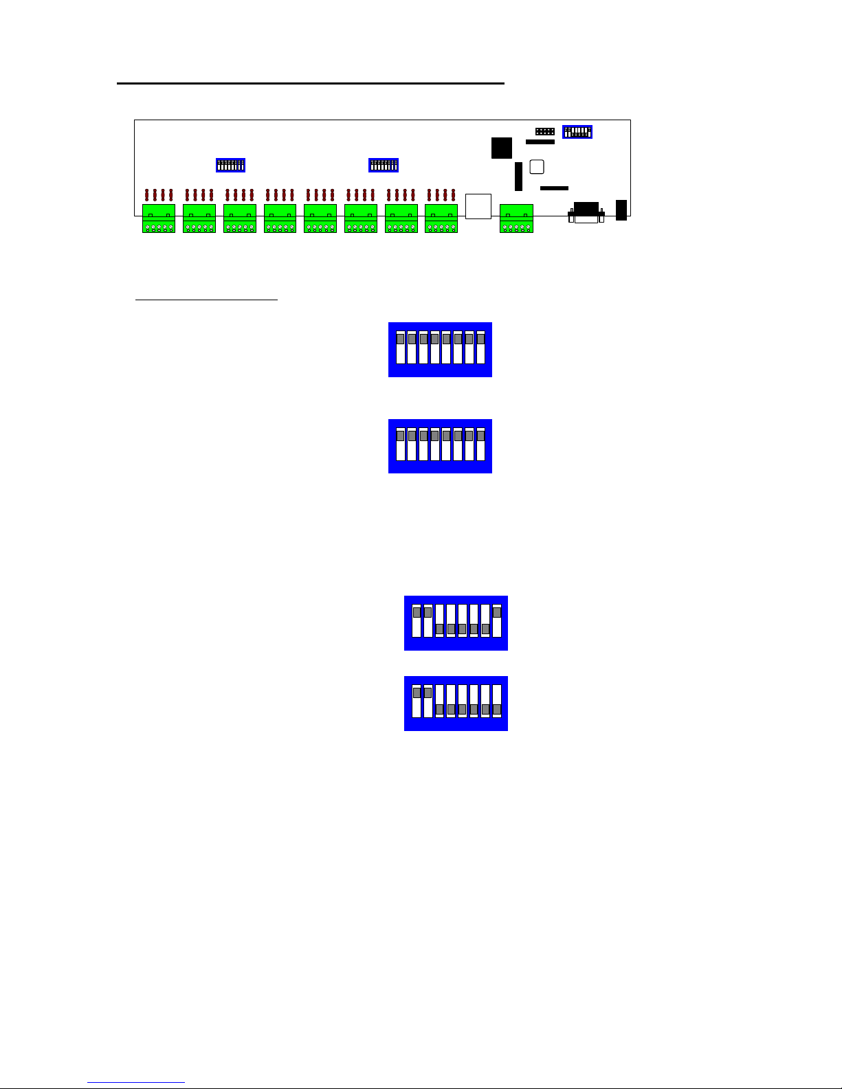
Internal view of starcard showing switch settings
Starcard PCB Switches
SW1 - RS485 line termination for outputs 1 - 4 ON = termination ON (Default)
SW1/1 & 1/2 = Output 1 termination
SW1/3 & 1/4 = Output 2 termination
SW1/5 & 1/6 = Output 3 termination
SW1/7 & 1/8 = Output 4 termination
SW2 - RS485 line termination for outptus 5 - 8 ON = termination ON (Default)
SW2/1 & 2/2 = Output 5 termination
SW2/3 & 2/4 = Output 6 termination
SW2/5 & 2/6 = Output 7 termination
SW2/7 & 2/8 = Output 8 termination
SW3 - Option selection.
SW3/1 and SW3/2 - RS485 input line termination ON = termination ON (Default)
SW3/3-7 MUST BE OFF
SW3/8 - 2 or 4 wire selection. ON = 2 WIRE, OFF = 4 WIRE
SW3
SW1
SW2
SW3 setting showing 2 wire mode selected
and RS485 input termination ON
1 2 3 4 5 6 7 8
SW3 setting showing 4 wire mode selected
and RS485 input termination ON
1 2 3 4 5 6 7 8
1 2 3 4 5 6 7 8
1 2 3 4 5 6 7 8
SW1 setting showing termination ON
SW2 setting showing termination ON
00007-3
J22
J15
J14
J16
Page 7
RS485 Star Card Manual V14 4Feb04.doc Page 7/29
RBR
A
T
R
B
T
R
A
G
N
D
To dome RA(+)/TRA
To dome RB(-)/TRB
Frame ground
Star n
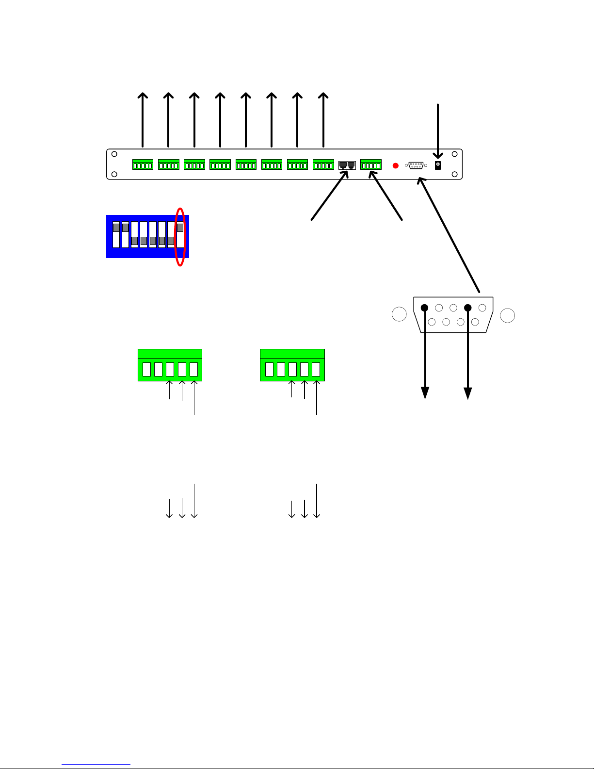
2 wire half-duplex mode
Close up view showing RS485 connection into and out of the Star Card.
RS485 network length maximum
1200M per output.
Please remember to terminate
the last dome of each output.
RBR
A
T
R
B
T
R
A
G
N
D
From controller TA(+)
From controller TB(-)
Frame ground
MASTER
2 wire RS485 notes.
1. Ensure that the dome/receiver is set for 2 wire telemetry, half-duplex.
2. The controller must be set for 2 wire using either a rear panel switch or menu access. Half duplex must be
selected from within the setup menu.
3. Baud rates for the controller and dome/receivers must be the same. It is advisable to use 9600 baud to reduce
the possibility of corrupted data causing intermittent control.
Panasonic Specific notes:
FS616 - A single RS485 output is available. Connect the RS485 output to the star card as shown.
SX350 - Two RS485 outputs are available.
SX550/850 - Not required as each matrix RS485 output card has eight individual outputs.
Star 8Star 7Star 6Star 5Star 4Star 3Star 2Star 1
BBV Starcard
RS232 monitor
8 * RS485 OUT
Supply
9Vdc 500mA
Master
RS485 INBBV RS485 or
1 2 3 4 5 6 7 8
SW3 must be configured for 2 Wire
as below: SWITCH 8 ON
5 4 3 2 1
9 8 7 6
GND to
PC pin 5
TX to
PC pin 2
The RS232 output can be taken into
a PC/laptop to allow the Starcard
output to be displayed using
Hyperterminal, Telix or other comms
program.
The baud and parity settings should
match the values chosen with SW2.
Page 8
RS485 Star Card Manual V14 4Feb04.doc Page 8/29
RBR
A
T
R
B
T
R
A
G
N
D
To dome RA(+)
To dome RB(-)
Frame ground
From dome TB(-)
From dome TA(+)
Star n
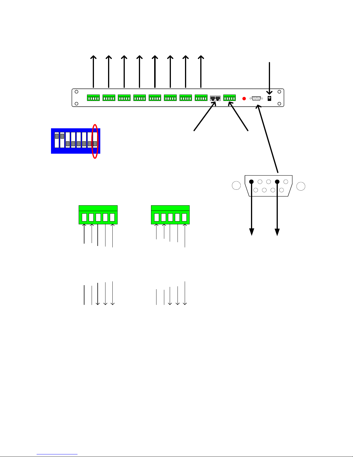
4 wire full-duplex mode
Close up view showing RS422 connection into and out of the Star Card.
RS422 network length maximum
1200M per output.
Please remember to terminate
the last dome of each output.
RBR
A
T
R
B
T
R
A
G
N
D
To controller RB(-)
Frame ground
From controller TB(-)
From controller TA(+)
To controller RA(+)
MASTER
4 wire RS422 notes.
1. Ensure that the dome/receiver is set for 4 wire telemetry, full-duplex.
2. The controller must be set for 4 wire using either a rear panel switch or menu access. Full duplex must be
selected from within the setup menu.
3. Baud rates for the controller and dome/receivers must be the same. It is advisable to use 9600 baud to reduce
the possibility of corrupted data causing intermittent control.
Panasonic Specific Notes:
FS616 - A single RS485 output is available. Connect the RS485 output to the star card as shown.
SX350 - Not compatible with 4 wire telemetry.
SX550/850 - Not required as each matrix RS485 output card has eight individual outputs.
Star 8Star 7Star 6Star 5Star 4Star 3Star 2Star 1
BBV Starcard
RS232 monitor
8 * RS422 OUT
Supply
9Vdc 500mA
Master
RS422 INBBV RS422 or
1 2 3 4 5 6 7 8
SW3 must be configured for 4 Wire
as below: SWITCH 8 OFF
5 4 3 2 1
9 8 7 6
GND to
PC pin 5
TX to
PC pin 2
The RS232 output can be taken into
a PC/laptop to allow the Starcard
output to be displayed using
Hyperterminal, Telix or other comms
program.
The baud and parity settings should
match the values chosen with SW2.
Page 9
RS485 Star Card Manual V14 4Feb04.doc Page 9/29
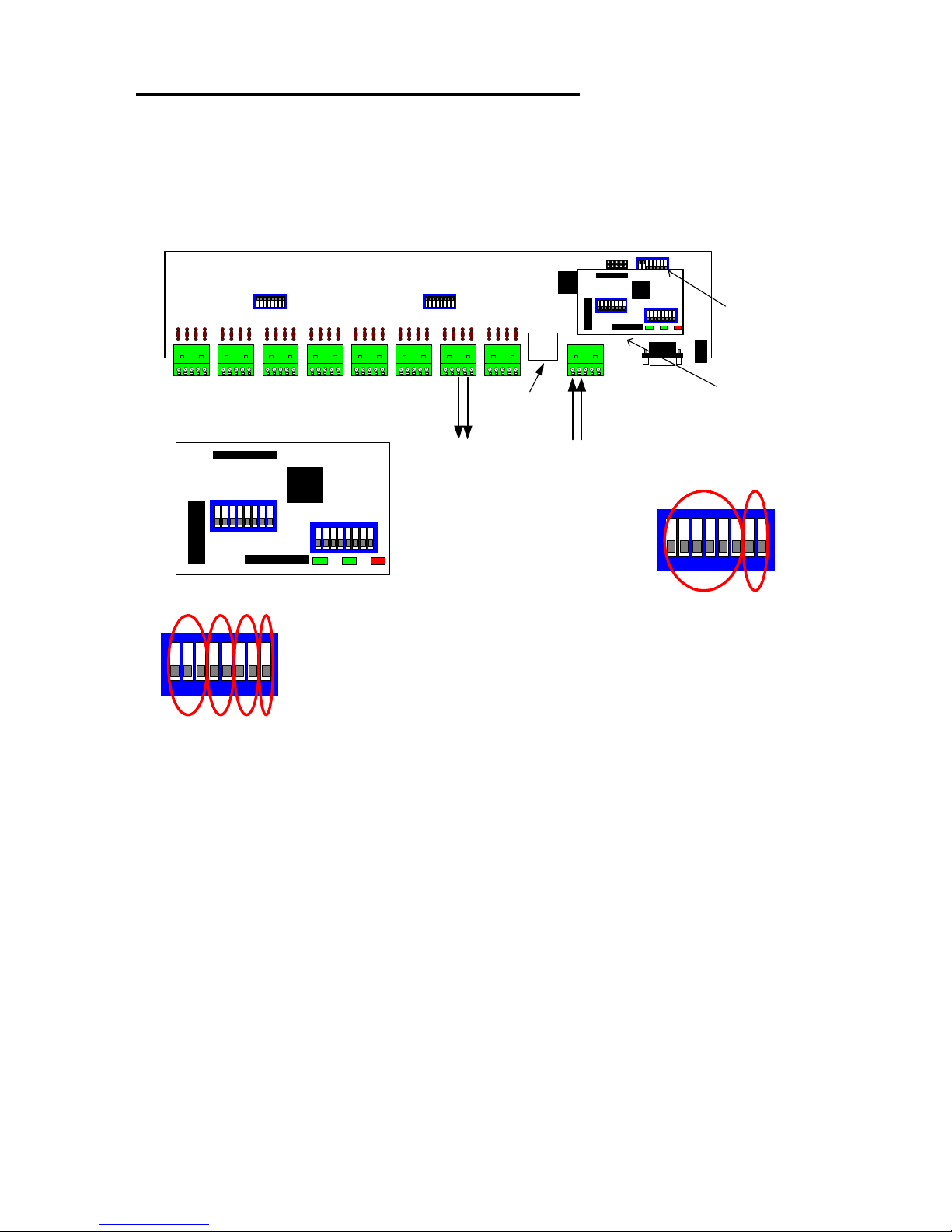
Internal view showing optional protocol converter
IMPORTANT NOTE.
When using the protocol converter, ensure that the starcard is set for 4 wire
telemetry using SW3/8 OFF. RS485 data IN to MASTER RA/RB or BBV
TELEMETRY IN with a TX1500 and data OUT to domes on STAR
TRA/TRB.
SW3
SW1
SW2
00007-3
J22
J15
J14
J16
SW1
SW2
02003
Protocol conversion card (02003)
fitted over headers J14, J15, J22.
Close up view of protocol
conversion card.
SW1
SW2
02003
LD1 LD2 LD3
LD1 = RS485 out
LD2 = RS485 in
LD3 = Checksum ERROR
SW3/8 OFF
to select 4 WIRE
SW2(1-6) Output Protol Selection
1 2 3 4 5 6 PROTOCOL BAUD
OFF OFF OFF OFF OFF OFF SELF TEST 9600,N,8,1
ON OFF OFF OFF OFF OFF DEBUG MODE 19200,N,8,1
OFF ON OFF OFF OFF OFF DENNARD 2050 9600,N,8,1
ON ON OFF OFF OFF OFF MARK MERCER 9600,N,8,1
OFF OFF ON OFF OFF OFF VCL 9600,N,8,1
ON OFF ON OFF OFF OFF PANASONIC 850 9600,N,8,1
OFF ON ON OFF OFF OFF PANASONIC 850 19200,N,8,1
ON ON ON OFF OFF OFF BBV RS485 9600,N,8,1
OFF OFF OFF ON OFF OFF JVC TK-C676 9600,E,8,1
ON OFF OFF ON OFF OFF BBV RX450/RX550 9600,N,8,1
OFF ON OFF ON OFF OFF CHUGAI ZC-S122 9600,E,8,1
ON ON OFF ON OFF OFF MOLYNX 9600,E,8,1
OFF OFF ON ON OFF OFF PELCO P 9600,N,8,1
ON OFF ON ON OFF OFF PELCO P 9600,O,8,1
OFF ON ON ON OFF OFF PELCO P 9600,E,8,1
ON ON ON ON OFF OFF PELCO P 2400,N,8,1
OFF OFF OFF OFF ON OFF PELCO P 2400,O,8,1
ON OFF OFF OFF ON OFF PELCO P 2400,E,8,1
OFF ON OFF OFF ON OFF PELCO D 9600,N,8,1
ON ON OFF OFF ON OFF PELCO D 9600,O,8,1
OFF OFF ON OFF ON OFF PELCO D 9600,E,8,1
ON OFF ON OFF ON OFF PELCO D 2400,N,8,1
OFF ON ON OFF ON OFF PELCO D 2400,O,8,1
ON ON ON OFF ON OFF PELCO D 2400,E,8,1
OFF OFF OFF ON ON OFF 360 VISION 9600,N,8,1
ON OFF OFF ON ON OFF CHUGAI SMD20 9600,N,8,1
OFF ON OFF ON ON OFF VICON 9600,N,8,1
ON ON OFF ON ON OFF VISTA POWERDOME 9600,N,8,1
OFF OFF ON ON ON OFF SAMSUNG SCC641/643 9600,N,8,1
ON OFF ON ON ON OFF MEYERTECH VICTA 9600,N,8,1
Data IN
RA/RB
Data OUT
TRA/TRB
SW2 Output Settings
1 2 3 4 5 6 7 8
RJ45 from
Tx1500
TELEMETRY
1 - 3 Protocol Selection
1 2 3 Protocol
OFF OFF OFF BBV RS485
(TX1500)
ON OFF OFF PELCO P
OFF ON OFF PELCO D
ON ON OFF VCL TP
4 - 5 Baud
4 5 Baud
OFF OFF 2400
ON OFF 4800
OFF ON 9600
ON ON 19200
6 - 7 Parity
6 7 Parity
OFF OFF NONE
ON OFF EVEN
OFF ON ODD
ON ON NONE
8 Data bits
OFF 8 BITS
ON 7 BITS
1 2 3 4 5 6 7 8
SW1 Input Settings
Page 10

RS485 Star Card Manual V14 4Feb04.doc Page 10/29
RS232 serial port.
The DB9F connector provides the ability to use a Laptop PC to monitor the
data being sent out of the StarCard via RS232.
With the optional protocol converter fitted, on power up or if SW1 or SW2
switches are altered the unit sends the current protocol, baud rate and parity
settings. Please be aware that the laptop baud rate and parity must match
the settings selected with SW2. If the settings do not match then the laptop
display will have no meaning.
An power up message example is shown below :
BBV Protocol Converter V14
www.bbvcctv.com
SW1(IN) = 10 BBV:9600,N,8,1
SW2(OUT) = A3 MARK MERCER V7.3:9600,N,8,1
A debug mode can also be selected which provides detailed information for
each command received. Whilst trouble shooting BBV engineers may ask
you to use this mode with a laptop or other PC.
BBV Protocol Converter V13
www.bbvcctv.com
SW1(IN) = 10 BBV:9600,N,8,1
SW2(OUT) = 21 DEBUG MODE:19200,N,8,1
CAM=00 W3=00 W4=14 W5=40 W6=24 PL 064TD 036
CAM=00 W3=00 W4=14 W5=06 W6=3C PL 006TD 060
CAM=00 W3=00 W4=12 W5=2E W6=38 PR 046TD 056
CAM=00 W3=00 W4=12 W5=40 W6=08 PR 064TD 008
CAM=00 W3=00 W4=08 W5=00 W6=0C TU 012
CAM=00 W3=00 W4=04 W5=40 W6=00 PL 064
CAM=00 W3=00 W4=14 W5=32 W6=34 PL 050TD 052
CAM=00 W3=00 W4=12 W5=2A W6=38 PR 042TD 056
CAM=00 W3=00 W4=04 W5=36 W6=00 PL 054
CAM=00 W3=00 W4=00 W5=00 W6=00 Cam 00 stop
The example above shows the debug output for camera 1. Driving pan/tilt
followed by a stop command.
Page 11

RS485 Star Card Manual V14 4Feb04.doc Page 11/29
The following table shows the possible input and output protocols that are supported with
this version of software.
Input Protocol
Output Protocol BBV/TX1500 PELCO D/P VCL
DENNARD 2050 X X
MARK MERCER X X
VCL TP X X
PANASONIC CS850/860 X
BBV RS485 (RX457/557) X X
JVC TKC676 X X
BBV RX450/550 X X
GANZ ZCS122/123 X
MOLYNX 250/260 X
PELCO D/P X
360 VISION X X
CBC SMD20 X
VICON X
VISTA POWERDOME X
SAMSUNG SCC641/643 X
MEYERTECH VICTA X
Page 12
RS485 Star Card Manual V14 4Feb04.doc Page 12/29
Protocol specific information
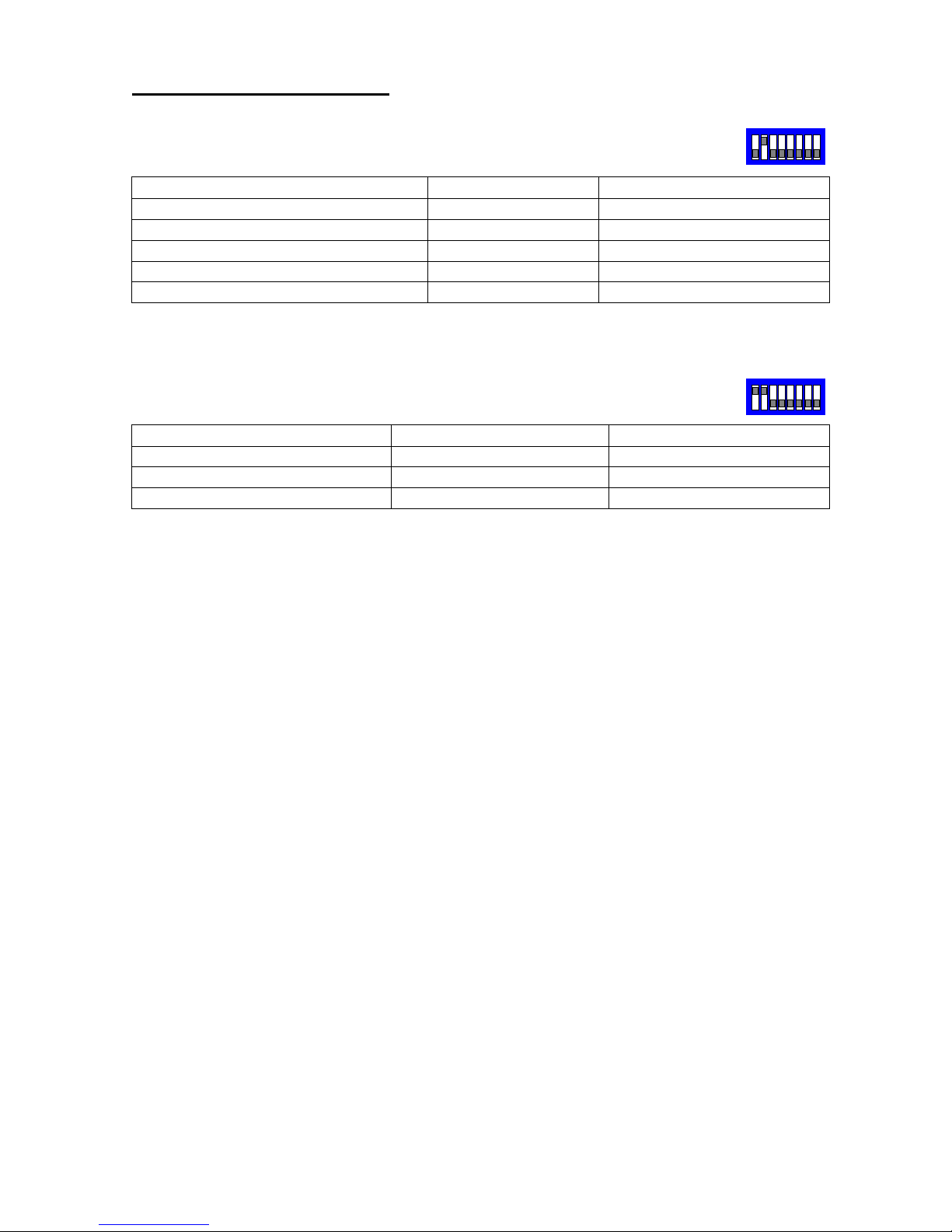
DENNARD 2050 – Fixed at 9600,N,8,1 (adjust SW1 to suit input protocol)
Function TX1500 Procedure Pelco Procedure
Display Dome Menu
1 #
SAVE PRESET 95
Display User Menu
2 #
GOTO PRESET 33
Display Technicians Menu
3 #
GOTO PRESET 94
Start current dome’s Sequence 001
1 PATROL
GOTO PRESET 97
Start ALL DOMES Sequence 001
2 PATROL
GOTO PRESET 98
Navigate through the dome menu using pan/tilt and issue GOTO PRESET 1 to select
current line.
MARK MERCER – Fixed at 9600,N,8,1 (adjust SW1 to suit input protocol)
Function TX1500 Procedure Pelco Procedure
180 Pan U turn
1 # or WASH
SAVE PRESET 95
Start current dome’s patrol
1 PATROL
GOTO PRESET 97
Start ALL DOMES patrol
2 PATROL
GOTO PRESET 98
SW2
SW2
Page 13
RS485 Star Card Manual V14 4Feb04.doc Page 13/29
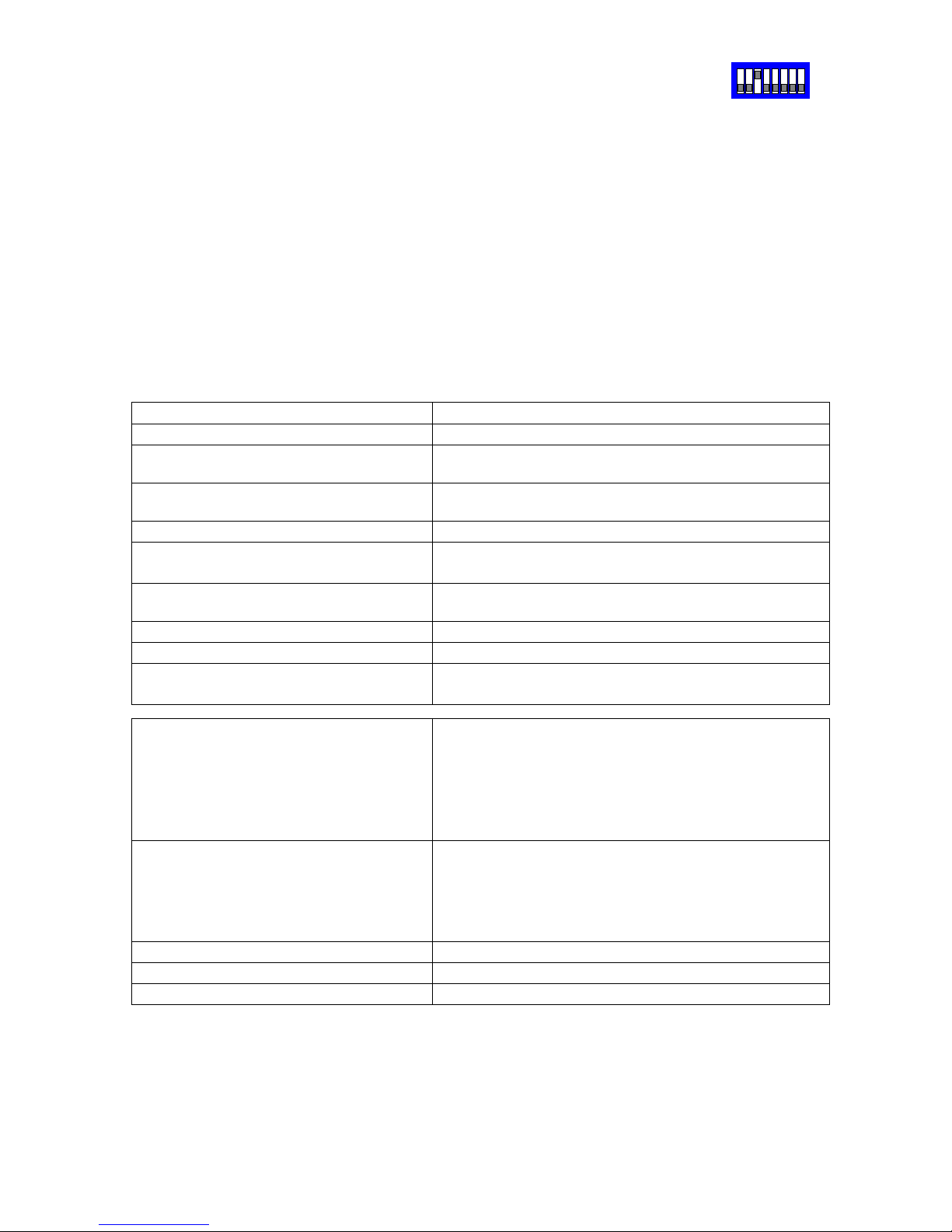
VCL TP – Fixed at 9600,N,8,1 (adjust SW1 to suit input protocol)
Connect dome D+ to Starcard/Converter TRA and dome D- to Starcard/Converter TRB.
Set the dome address using the DIL switch to match the number of the camera input of
the TX1500. Ensure that any dome at the end of a daisy chained RS485 run are have the
RS485 terminated and the intermediate domes have the RS485 determinated.
The following functionality is provided.
Manual pan/tilt control with 16 speed steps from 1 to 127, (slowest to fastest)
Zoom with Manual Iris and Focus override.
Operating the Zoom will re-enable auto focus and iris after manual adjustment
32 preset positions.
2 sequential preset tours of preset positions 1 - 16, tour 1 maximum speed and tour 2
speed 32. The dwell time is fixed at 10 seconds per preset position. Preset positions can
be removed from the tours.
All 28 privacy zones can be programmed and disabled if required.
Advanced Function TX1500 Procedure
Manual 180 degree pan flip (U turn)
1 #
Program a privacy zone 2 # followed by
PROGRAM 1-28 PRESET
Clear a privacy zone 3 # followed by
PROGRAM 1-28 PRESET
Dome remote reset (power cycle)
4 #
Add preset position to the tours programming a preset position adds the preset
into the tour. (1 – 16 only)
Remove a preset from the tours PROGRAM 50 PRESET followed by
1-16 PRESET
Start preset tour 1 – high speed 1 PATROL (max speed with 10 second dwell)
Start preset tour 2 – slow speed 2 PATROL (speed 32 with 10 second dwell)
Start Learned tour 5 AUTOPAN (must be defined with PROGRAM 56
PRESET as below)
Set Home functions
(fixed at 5 minutes)
PROGRAM 54 PRESET followed by
1 PRESET = Enable to preset 1
2 PRESET = Enable to tour 1 (fast)
3 PRESET = Enable to tour 2 (slow)
4 PRESET = Enable to learned tour (autopan)
5 PRESET = Disable home
Reset dome to factory. USE
CAUTION!!
This command will clear all dome
configuration including preset
positions.
PROGRAM 55 PRESET followed by
PROGRAM 55 PRESET
Define learned tour 5 – START
PROGRAM 56 PRESET
Define learned tour 5 – STOP
PROGRAM 57 PRESET
Enable AUTO180 pan flip
PROGRAM 58 PRESET
SW2
Page 14

RS485 Star Card Manual V14 4Feb04.doc Page 14/29
VCL TP – When using Pelco input protocol
Advanced Function Pelco procedure
180 degree pan flip (U turn) SAVE PRESET 95
Program a privacy zone GOTO PRESET 33 followed by
PROGRAM 1-28 PRESET
Clear a privacy zone GOTO PRESET 94 followed by
PROGRAM 1-28 PRESET
Dome remote reset
(power cycle)
Head reset
Add preset position to the tours Saving a preset position adds the preset into the tour. (1
– 16 only)
Remove a preset from the tours PROGRAM 50 PRESET followed by
GOTO PRESET 1-16
Start preset tour 1 – high speed GOTO PRESET 97 (max speed with 10 second dwell)
Start preset tour 2 – slow speed GOTO PRESET 98 (speed 32 with 10 second dwell)
Start Learned tour 5 GOTO PRESET 99 (must be defined with SAVE
PRESET 56 as below)
Set Home functions
(fixed at 5 minutes)
PROGRAM 54 PRESET followed by
GOTO PRESET 1 = Enable to preset 1
GOTO PRESET 2 = Enable to tour 1 (fast)
GOTO PRESET 3 = Enable to tour 2 (slow)
GOTO PRESET 4 = Enable to learned tour (PRESET 99)
GOTO PRESET 5 = Disable home
Reset dome to factory. USE
CAUTION!!
This command will clear all
dome configuration including
preset positions.
SAVE PRESET 55 followed by
SAVE PRESET 55
Define learned tour 5 – START SAVE PRESET 56
Define learned tour 5 – STOP SAVE PRESET 57
Enable AUTO180 pan flip SAVE PRESET 58
Page 15
RS485 Star Card Manual V14 4Feb04.doc Page 15/29
PANASONIC WV-CS850/860 (Added in V 4 software)
Control from BBV protocol only.
Function TX1500 Procedure
Show/Hide dome Menu
1 #
ENTER (whilst in menu)
2 #
ESCAPE (whilst in menu)
3 #
SPECIAL2 (whilst in menu)
4 #
Send PATROL RUN
1 PATROL
Send PATROL RUN to ALL DOMES
2 PATROL
Send AUTOPAN
AUTOPAN
BW MODE ON
89 PRESET
BW MODE OFF
88 PRESET
BW MODE AUTO
87 PRESET
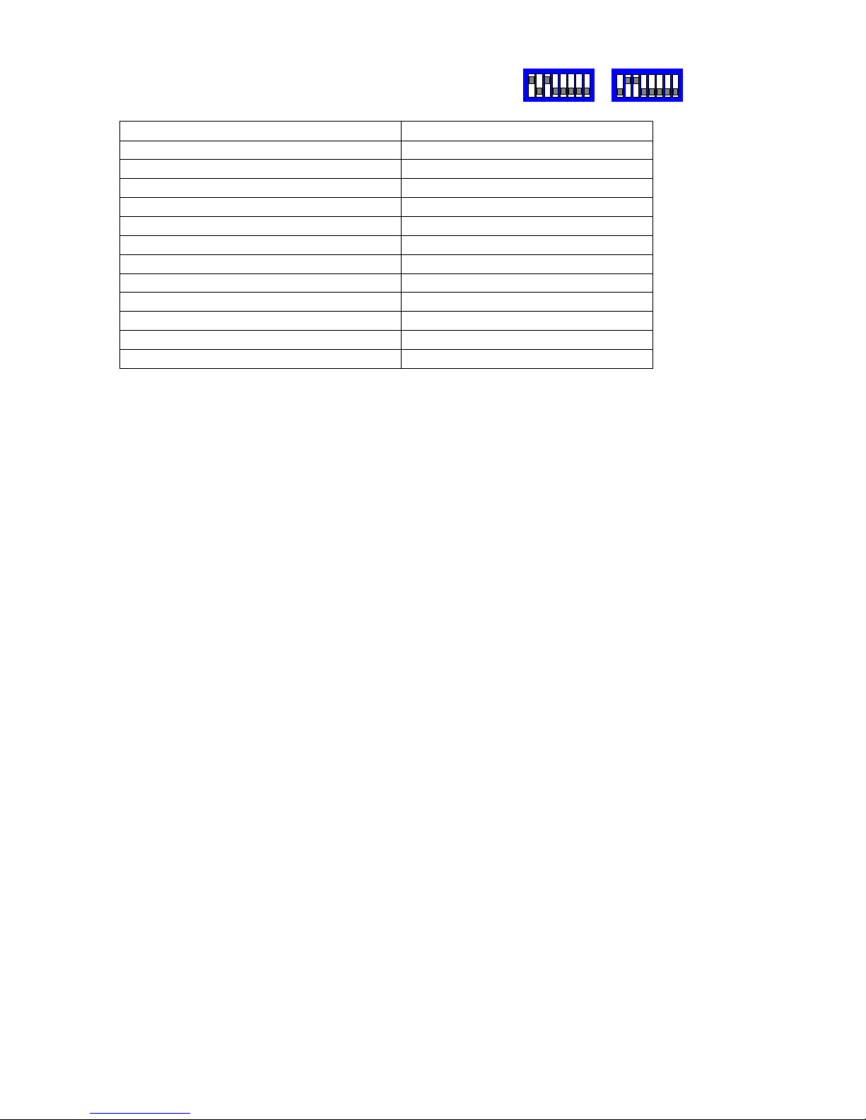
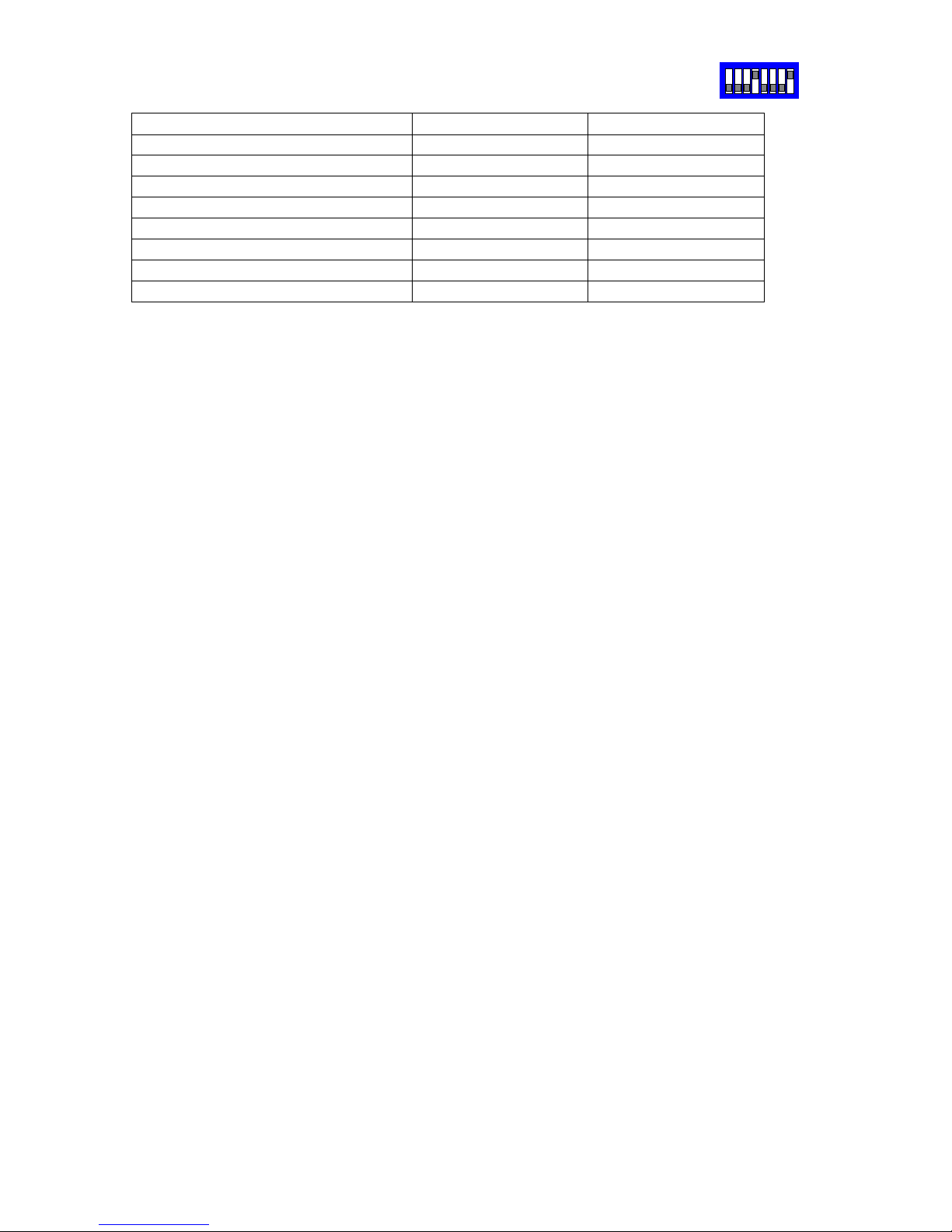
Switch and dome settings:
VERY IMPORTANT! Ensure that each dome is configured BEFORE installation.
Output baud rate must be set to 19200,N,8,1 with SW2.
The dome must be set to Panasonic CONVENTIONAL protocol and the address set
accordingly.
The 4 way dome switch must be set to 4 wire telemetry with switches 2,3,4 OFF.
The RS485 cable requires termination at the end of the run by setting switch 1 ON.
The Panasonic CS850/860 protocol conversion is only available when controlled using
BBV RS485 telemetry. If another input protocol is selected using SW1 then the unit will
not function and all the LEDs will flash until BBV protocol is selected again.
Due to protocol issues, the response of an individual dome may become sluggish if
several domes are controlled simultaneously.
Connect TRA to RA(green) and TRB to RB(yellow).
9600,N,8,1 or 19200,N,8,1
Page 16
RS485 Star Card Manual V14 4Feb04.doc Page 16/29
JVC TK-C676 – Fixed at 9600,E,8,1 (adjust SW1 to suit input protocol)
Function TX1500 Procedure Pelco Procedure
Display menu and EXIT
1 #
SAVE PRESET 95
SET (whilst in menu)
2 #
GOTO PRESET 33
Toggle Extended Dynamic Range
3 #
GOTO PRESET 94
Cycle BW mode, ON/OFF/AUTO
4 #
Start dome AUTO PATROL
1 PATROL
GOTO PRESET 97
As above for ALL DOMES
2 PATROL
GOTO PRESET 98
Start dome AUTOPAN
AUTOPAN
GOTO PRESET 99
Notes:
Connect dome RX- to Starcard TRB and dome RX+ to Starcard TRA.
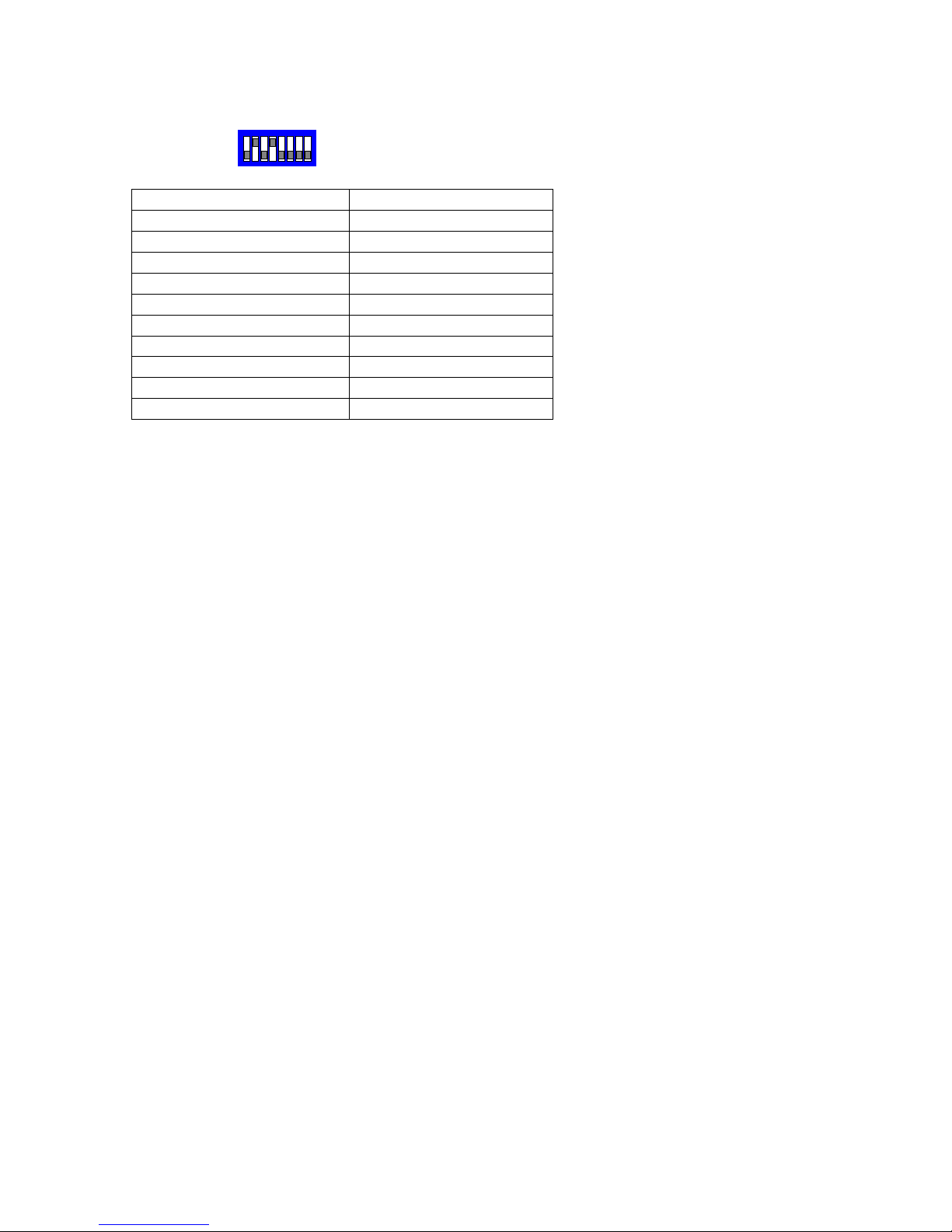
Each dome must be set to Multi-drop, Simplex mode by setting dome switch 4 & 5 ON.
Set each dome address using the dome rotary switches. This address must match the
number of the camera input of the telemetry controller.
A total of up to 96 domes are supported with a maximum of 32 domes per star output.
To display the current dome’s menu, press either 1# with the BBV Tx1500 or SAVE
PRESET 95 using Pelco-P or Pelco-D protocol. Use standard PAN/TILT and where
required ZOOM to navigate through the menus. To simulate the SET key to navigate into
sub-menus press 2# with a TX1500 or GOTO PRESET 33 when using Pelco protocols.
To exit the current menu press 1# for the TX1500 or SAVE PRESET 95 with Pelco.
Addition functions.
Pressing AUTOPAN with a TX1500 or GOTO PRESET 99 with Pelco will cause the
current dome to start an AUTOPAN.
Pressing 1 PATROL with a TX1500 or GOTO PRESET 97 with Pelco will cause the
current dome to start an AUTOPATROL.
Pressing 2 PATROL with a TX1500 or GOTO PRESET 98 with Pelco will cause ALL the
domes to start an AUTOPATROL.
Extended Dynamic Range can be toggled ON/OFF using 3# with the TX1500 or GOTO
PRESET 94 with Pelco.
B/W Mode can be cycled between ON/OFF/AUTO using 4# with the TX1500.
Camera mode display. Protocol Converter SW2/8
If protocol converter switch SW2/8 is set to ON then each time the Extended Dynamic
Range or BW mode is changed or AUTOPATROL is selected then the dome title is
altered to display these settings. If it is preferred to use the dome camera title for titling
then set switch SW2/8 OFF. The settings will still be changed but will not be shown.
Presets
The dome home preset position is preset 0. As most control systems do not directly
support preset 0, preset 1 is used instead. This means that in practice, preset 1 is home,
preset 2-32 are preset 2-32 and the dome’s preset 1 is not used. This could only be an
issue when programming alarms directly into the dome. Do not use preset position 1
unless this is programmed from within the dome menu.
SW2
Page 17
RS485 Star Card Manual V14 4Feb04.doc Page 17/29
Chugai/Ganz ZC-S122/123 – Fixed at 9600,E,8,1 Control from BBV protocol only.
SW2
Function TX1500 Procedure
Menu ON/OFF
1 #
SET (whilst in menu)
2 #
CLR (whilst in menu)
3 #
PRESET SEQUENCE
1 PATROL
PLAYBACK TRACE
2 PATROL
AUTOPAN
AUTOPAN
AUX 1 OUTPUT ON/OFF
LIGHTS
AUX 2 OUTPUT ON/OFF
WIPER
Notes:
Connect dome A/+(pin 1, BROWN) to Starcard TRA and dome B/- to Starcard TRB.
Each dome must be set to 9600 Baud with switch 5 OFF, switch 6 ON. Set the dome
address using the dome rotary switches to match the number of the camera input of the
TX1500. Ensure that domes at the end of the RS485 run are terminated by turning
switch 8 ON and the intermediate domes have the switch 8 OFF.
A total of up to 96 domes are supported with a maximum of 32 domes per star output.
Menu access.
Press 1# will toggle the Menu display ON/OFF.
Whilst the menu is displayed the joystick is used to navigate.
2# is used as SET to access a menu option and
3# is used as CLR to go back.
Addition functions are available for the currently displayed dome.
AUTOPAN is started by pressing the AUTOPAN key.
PRESET SEQUENCE is started by pressing 1 PATROL.
TRACE playback is started by preseding 2 PATROL
The protocol converter can directly access preset 1 – 64 by pressing the preset number
followed by the PRESET key.
To program a preset position, press PROGRAM followed by the preset number and the
PRESET key. See the TX1500 manual for detailed information.
Page 18

RS485 Star Card Manual V14 4Feb04.doc Page 18/29
Molynx 250/260 – Fixed at 9600,E,8,1 Control from BBV protocol only.
Function TX1500 Procedure
PRESET 1 – 32 As manual
WASH, WIPE, LIGHTS
AUX1 TOGGLE
1 #
AUX2 TOGGLE
2 #
RECEIVER INITIALISE
4 #
Notes:
Connect receiver + to Starcard TRA and receiver - to Starcard TRB.
Set the receiver address switches to match the number of the camera input of the
TX1500.
Molynx receivers can only be controlled when using BBV telemetry into the StarCard ie
from the BBV Tx1500 matrix.
Control of the receiver auxiliary relays is possible using the Tx1500 Wash, Wipe and
Lights keys. Additionally the AUX1 and AUX2 outputs can be toggled using 1# and 2#
respectively.
Up to 32 preset positions can be programmed and recalled.
A preset patrol is not supported.
SW2
Page 19

RS485 Star Card Manual V14 4Feb04.doc Page 19/29
PELCO P and PELCO D.
Function TX1500 Procedure Pelco Procedure
Display Dome Menu
1 #
SAVE PRESET 95
180 degree pan flip (U turn)
2 #
GOTO PRESET 33
Display Technicians Menu
3 #
GOTO PRESET 94
Start Random Scanning
PATROL 1
GOTO PRESET 97
Start Frame Scanning
PATROL 2
GOTO PRESET 98
This allows control of Pelco P and Pelco D units. Please ensure that the baud rate and
parity are set correctly. Generally Pelco P uses 9600,N,8,1 and Pelco D uses 2400,N,8,1.
Page 20
RS485 Star Card Manual V14 4Feb04.doc Page 20/29
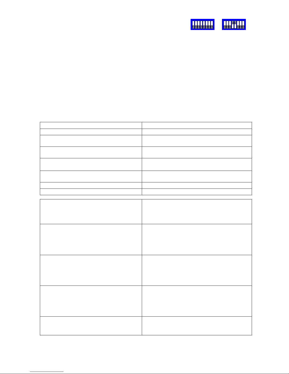
360 VISION from BBV telemetry.
Connect dome D+ to Starcard/Converter TRA and dome D- to Starcard/Converter TRB.
Set the dome address using the DIL switch to match the number of the camera input of
the TX1500. Ensure that the dome at the end of a daisy chained RS485 run has the
RS485 terminated and the intermediate domes have the RS485 de-terminated.
The following functionality is provided.
Manual pan/tilt control with 16 speed steps from 1 to 127, (slowest to fastest)
Zoom with Manual Iris and Focus override.
Operating the Zoom will re-enable auto focus and iris after manual adjustment
32 preset positions.
2 sequential preset tours of preset positions 1 - 16, tour 1 high speed and tour 2 slow
speed. The dwell time is fixed at 10 seconds per preset position. Preset positions can be
removed from the tours.
All 32 privacy zones can be programmed and disabled if required.
Advanced Function TX1500 Procedure
180 degree pan flip (U turn)
1 #
Program a privacy zone 2 # followed by
PROGRAM 1-32 PRESET
Clear a privacy zone 3 # followed by
PROGRAM 1-32 PRESET
Add preset position to the tours Programming a preset position adds the
preset into the tour. (1 – 16 only)
Remove a preset from the tours PROGRAM 50 PRESET followed by
1-16 PRESET
Start preset tour 1 – high speed 1 PATROL (max speed with 10 second dwell)
Start preset tour 2 – slow speed 2 PATROL (speed 32 with 10 second dwell)
Set autoflip mode PROGRAM 51 PRESET followed by
1 PRESET = autoflip OFF
2 PRESET = ON tilt at down limit
3 PRESET = ON when at limit
Set Video Gain/Lift and Sync timing PROGRAM 52 PRESET followed by
IRIS CLOSE/OPEN to increase/decrease GAIN
FOCUS NEAR/FAR to increase/decrease LIFT
ZOOM IN/OUT to advance/retard timing
Move joystick when finished.
Set IR Filter mode PROGRAM 53 PRESET followed by
1 PRESET = mono mode/auto off
2 PRESET = colour mode/auto off
3 PRESET = auto/kill colour
4 PRESET = auto/don’t kill colour
Set Home functions
(fixed at 5 minutes)
PROGRAM 54 PRESET followed by
1 PRESET = Enable to preset 1
2 PRESET = Enable to patrol 1 (fast)
3 PRESET = Enable to patrol 2 (slow)
4 PRESET = Disable home
Reset dome to factory. USE CAUTION!!
This command will clear all dome
configuration including preset positions.
PROGRAM 55 PRESET followed by
PROGRAM 55 PRESET
SW1
SW2
Page 21
RS485 Star Card Manual V14 4Feb04.doc Page 21/29
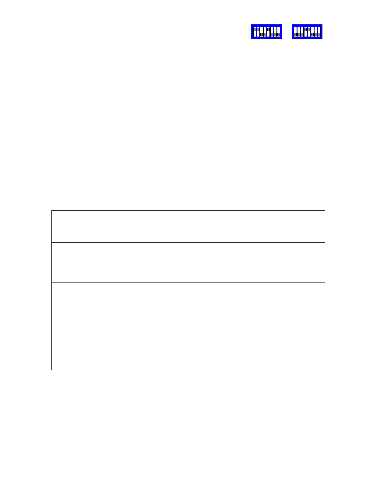
360 VISION from VCL telemetry.
Connect dome D+ to Starcard/Converter TRA and dome D- to Starcard/Converter TRB.
Set the dome address using the DIL switch to match the number of the camera input of
the TX1500. Ensure that the dome at the end of a daisy chained RS485 run has the
RS485 terminated and the intermediate domes have the RS485 de-terminated.
The following functionality is provided.
Manual pan/tilt control with 16 speed steps from 1 to 127, (slowest to fastest)
Zoom with Manual Iris and Focus override.
Operating the Zoom will re-enable auto focus and iris after manual adjustment
32 preset positions.
Preset 100 – 127 will program the dome privacy zone 1 – 27. These can be disabled
within the VCL privacy menu by setting the appropriate preset to PRESET. The dome will
move to show the privacy scene to allow toggling the privacy back on by selecting
PRIVATE.
Tour definitions are compatible with the VCL programming method 2 including dwell time
and speed per tour point.
The dome home feature can be programmed using the standard VCL control menu.
In addition to the standard functions offered by the VCL control system the following
features are available.
Set autoflip mode program preset 51 followed by
goto preset 1 = autoflip OFF
goto preset 2 = ON tilt at down limit
goto preset 3 = ON when at limit
Set Video Gain/Lift and Sync timing program preset 52 followed by
iris close/open to increase/decrease GAIN
focus near/far to increase/decrease LIFT
zoom in/out to advance/retard timing
Move joystick when finished.
Set IR Filter mode program preset 53 followed by
goto preset 1 = mono mode/auto off
goto preset 2 = colour mode/auto off
goto preset 3 = auto/kill colour
goto preset 4 = auto/don’t kill colour
Set Home functions
(fixed at 5 minutes)
program preset 54 followed by
goto preset 1 = Enable to preset 1
goto preset 2 = Enable to patrol 1 (fast)
goto preset 3 = Enable to patrol 2 (slow)
goto preset 4 = Disable home
Reset dome to factory. CAUTION!!! program preset 55 twice
SW1
SW2
Page 22

RS485 Star Card Manual V14 4Feb04.doc Page 22/29
CBC SMD20, STAR MD2000, SANYO VCC9200P from BBV telemetry.
Connect dome DATA+ to Converter TRA and dome DATA- to Converter TRB.
Set the dome address using the DIL switch to match the number of the camera input of
the TX1500. Ensure that the dome at the end of a daisy chained RS485 run has the
RS485 terminated and the intermediate domes have the RS485 de-terminated.
This type of dome can be addressed from 1 – 31. To allow use of more that 31 domes on
a Tx1500 system the converter can be adjusted to select banks of cameras as follows:
Camera Range SW2/7 SW2/8
1 – 31 OFF OFF (This is the default setting)
32 – 62 ON OFF
63 – 93 OFF ON
94 – 124 ON ON
When the converter is set for camera range 32 – 62, the dome connected into video
input 32 must have the address set for 1 and video input 33 must have the address set to
2 etc up to video input 62 with the address set to 31. Multiple Starcard/Converter must be
used when controlling more that 31 cameras with SW2/7 and SW/8 set appropriately.
i) Because of the nature of the dome protocol which uses half duplex command and
response commands timing to the dome is critical. If a command is sent to the dome
before it has finished executing the previous command, the new command is ignore!!!
Even if this is another goto preset command whilst the dome is searching for another
preset, say if get multiple alarm occurrences in quick succession. This would appear that
the controller hasn't sent the command to the dome... not the case.
ii) The converter is limited to control ONE dome at a time because of this timing. A
lockout period prevents other cameras on a single starcard from being controlled until 5
seconds after the last command has been sent to the current camera.
THIS INCLUDES PRESET COMMANDS...
iii) Supported manual ptz with manual focus which reverts back to auto focus on a pan/tilt
or zoom.
iv) 64 preset positions are supported
v) The AUTOPAN key is used to start patrol 2.
vi) 2 preset patrols are provided and the preset positions in each patrol are
programmable. Patrol 1 is has a fixed full speed movement to each preset and a dwell of
10 seconds. To define patrol 1, first PROGRAM 65 PRESET, followed by GOTO preset
for each of the presets to be patrolled. Up to 64 presets can be programmed. Obviously
each preset position must be programmed prior to defining the patrol. To end the
definition PROGRAM 66 PRESET.
Patrol 2 has a fixed slow speed movement between preset positions and again a 10
second dwell at each position. Programming follows the same idea as patrol 1.
PROGRAM 67 PRESET to start definition, goto preset ... followed by PROGRAM 68
PRESET to end the definition. Patrol 2 can also be started by pressing the AUTOPAN
key.
vii) LEDS, LD3 flashes when commands are received for domes that lie outside of the 31
camera range set by SW2/7 and SW2/8.
IMPORTANT... IF THE DOME IS MOVING TO A PRESET POSITION THE DOME WILL
IGNORE ALL COMMANDS THAT ARE SENT FROM THE CONVERTER UNTIL THE
PRESET POSITION HAS BEEN REACHED. THIS RELATES TO MANUAL PRESET OR
DURING A PATROL.
SW2
Page 23

RS485 Star Card Manual V14 4Feb04.doc Page 23/29
Vicon Surveyor from BBV
Connect dome COMM_IN+ to Starcard/Converter TRA and dome COMM_IN- to
Starcard/Converter TRB.
Set the dome address using the DIL switch to match the number of the camera input of
the TX1500. Ensure that any dome at the end of a daisy chained RS485 run are have the
RS485 terminated and the intermediate domes have the RS485 de-terminated.
Select VPS telemetry using dome DIP DIL.
The following functionality is provided.
Manual pan/tilt control with 16 speed steps.
Zoom with Manual Focus override.
Operating the Zoom will re-enable auto focus after manual adjustment
64 preset positions.
3 tours can be started, tour 81 and 82 using 1 PATROL and 2 PATROL and tour 80 with
AUTOPAN.
The tours are defined from the dome menu
Advanced Function TX1500 Procedure
Display dome menu
1 #
MENU AP – ENTER
IRIS OPEN
MENU AI – ESCAPE
IRIS CLOSE
MENU AUX1
WASH
MENU AUX2
WIPE
Start TOUR 81
1 PATROL
Start TOUR 82
2 PATROL
Start TOUR 80
AUTOPAN
It is very important that once you have exited the dome menu you send a 1 PRESET to
inform the starcard that you are out of the dome menu.
SW2
Page 24
RS485 Star Card Manual V14 4Feb04.doc Page 24/29
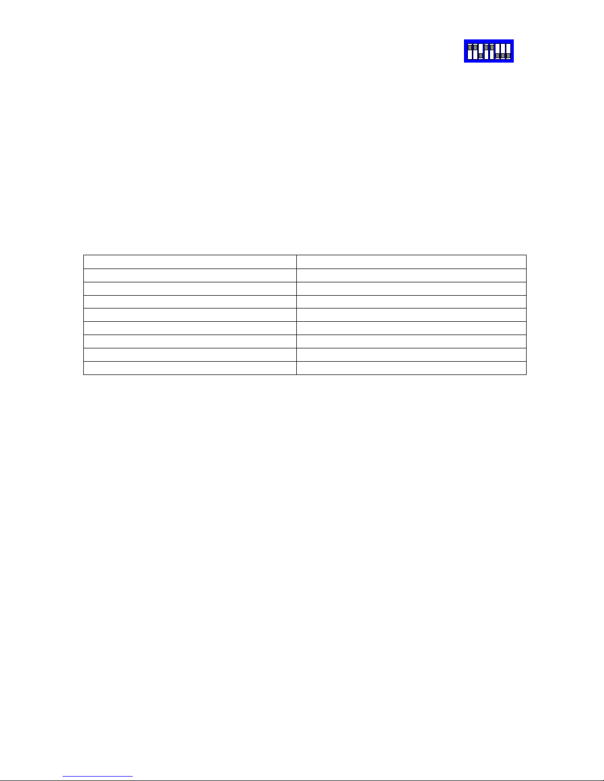
Vista PowerDome from BBV
Connect dome DATA IN A/+ to Starcard/Converter TRA and dome DATA IN B/- to
Starcard/Converter TRB.
Set the dome address using the DIL switch to match the number of the camera input of
the TX1500. Ensure that any dome at the end of a daisy chained RS485 run are have the
RS485 terminated and the intermediate domes have the RS485 de-terminated.
The following functionality is provided.
Manual pan/tilt control with 16 speed steps.
Zoom with Manual Focus override.
Operating the Zoom will re-enable auto focus after manual adjustment
64 preset positions.
3 tours can be started, TOUR 1 and 2 using 1 PATROL and 2 PATROL and LEARN
TOUR 1 with AUTOPAN.
The tours are defined from the dome menu which is accessed using 1 # as below.
Advanced Function TX1500 Procedure
Display dome menu
1 #
Menu – ENTER
2 #
Menu – ESCAPE
3 #
Start TOUR 1
1 PATROL
Start TOUR 2
2 PATROL
Learn 1 playback
AUTOPAN
SW2
Page 25
RS485 Star Card Manual V14 4Feb04.doc Page 25/29
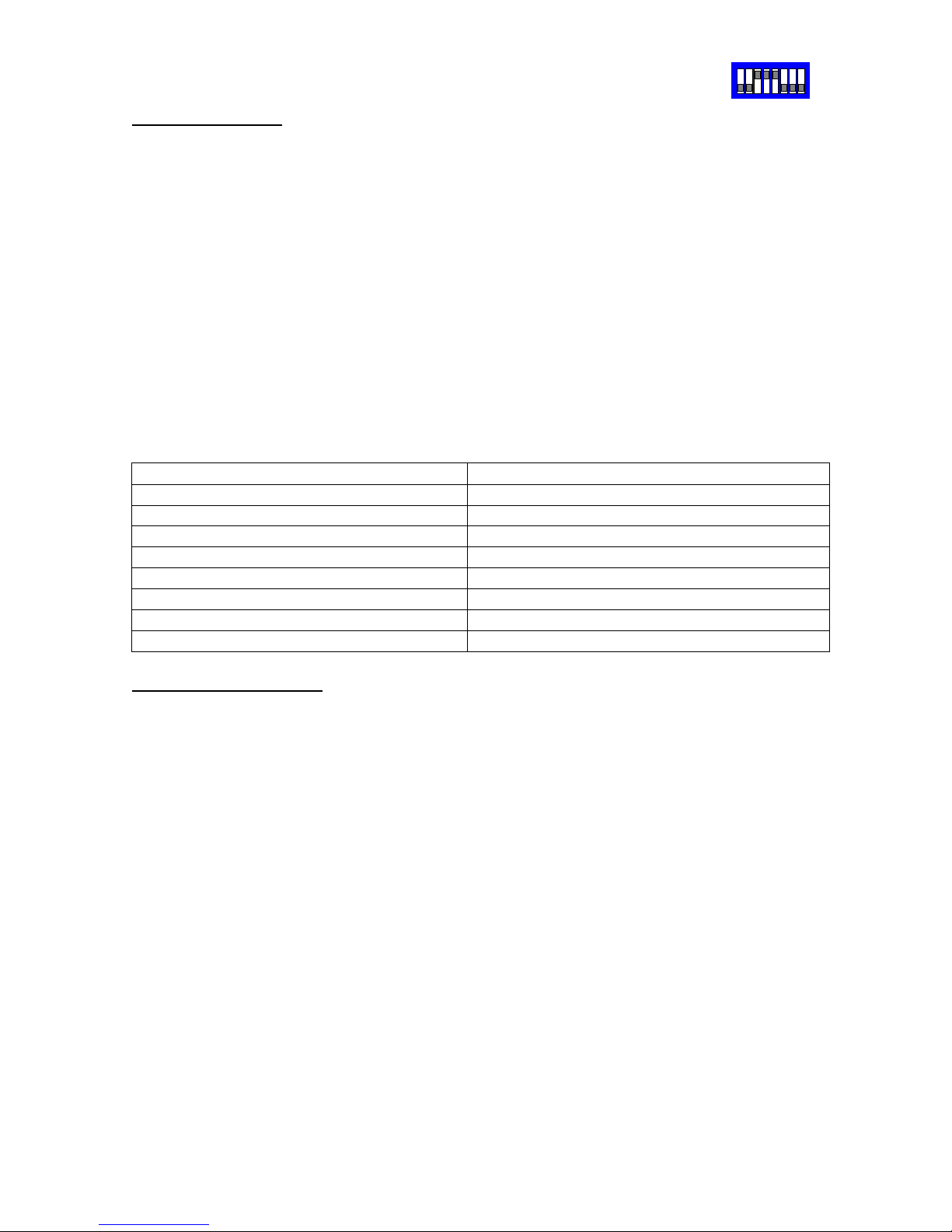
Samsung SCC641/643 dome and SCC421 camera from BBV
SCC641/643 dome
Connect dome RXD/+ to Converter TRA and dome RXD/- to Converter TRB.
Set the dome address using the SW500 switch to match the number of the camera input
of the TX1500. SW501 all off apart from 3 and 5 to select 9600 BAUD, SAMSUNG
protocol and FULL duplex. Ensure that any dome at the end of a daisy chained RS485
run are have switches SW501/1 and SW501/2 ON to terminate the RS485 terminated
and the intermediate domes have the SW501/1 and SW501/2 OFF.
The following functionality is provided.
Manual pan/tilt control with 16 speed steps.
Zoom with Manual Focus override.
Operating the Zoom will re-enable auto focus after manual adjustment
64 preset positions.
AUTOPAN can be started with the AUTOPAN key.
PRESET SCAN can be started using 1 PATROL.
PATTERN 2 can be started using 2 PATROL.
The patterns are defined from the dome menu which is accessed using 1 # as below.
Advanced Function TX1500 Procedure
Dome Menu ON
1 #
Dome Menu OFF
2 #
Dome Menu ENTER
3 #
Start PRESET SCAN
1 PATROL
Start PATTERN 2
2 PATROL
Start AUTOPAN
AUTOPAN
SCC421P Static camera
Connect the camera RS485 Data+ to Converter TRA and Data- to Converter TRB.
Ensure that BAUD RATE is set to 9600 and RS485 ADDR is set to match the video input
on the Tx1500 matrix. The buttons on the rear of the camera allow menu access.
Ensure that any camera at the end of a daisy chained RS485 run has the TERMINATION
switch ON and the intermediate camera have the TERMINATION switch OFF.
The following functionality is provided.
Zoom with Manual Focus override.
To allow manual focus set AUTO FOCUS in the menu to either ONEAF for MF.
ONEAF will cause an AUTOFOCUS after a zoom and MF is permanently in manual
focus mode.
Iris Open/Close.
SW2
Page 26

RS485 Star Card Manual V14 4Feb04.doc Page 26/29
Meyertech ZVR-510 receiver with VICTA protocol from BBV telemetry only.
Connect receiver 422 RX+ to Converter TRA and 422 RS- to Converter TRB.
Set the receiver address to match the number of the camera input of the TX1500.
The following functionality is provided.
Variable speed Pan/Tilt – 8 speeds
Zoom/Focus
WASH, WIPE, LIGHTS auxiliary outputs
32 preset positions.
The Meyertech protocol supports 8 speeds for pan and tilt. If the head is to pan and tilt
simultaneously then the same speed is used for both axis. For example if the head is
moving left at say speed 4 and then the joystick is moved up the head will now move left
at the new tilt speed. This is not a problem with the converter but a limitation of the
Meyertech protocol.
SW2
Page 27
RS485 Star Card Manual V14 4Feb04.doc Page 27/29
Star Card Star Card Star Card
Star Card
Control System
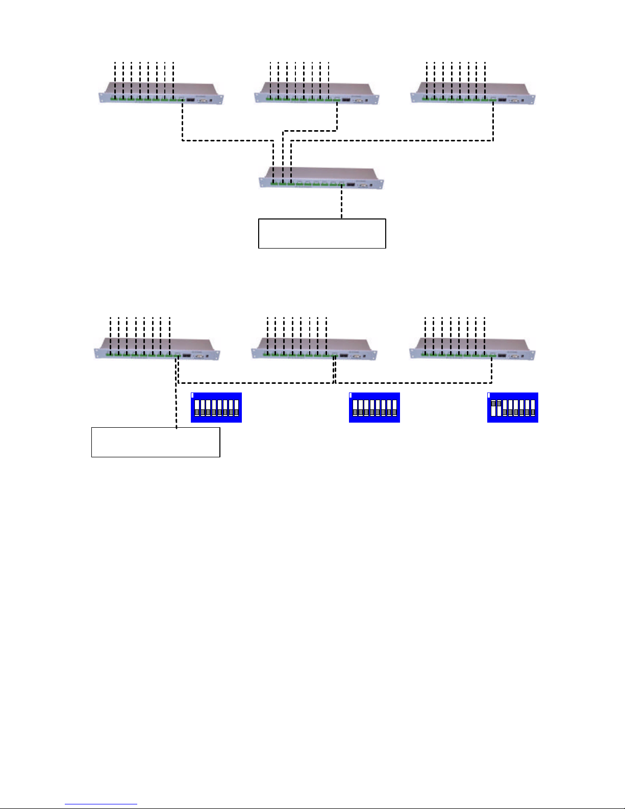
Star Cards can be cascaded
to suit each installation
RS485 to domes/receivers RS485 to domes/receivers RS485 to domes/receivers
Each leg
1200M Maximum
Each leg
1200M Maximum
Each leg
1200M Maximum
1200M Maximum
Star Card Star Card Star Card
Control System
On single direction RS485, multiple StarCards can be daisy chained to provide multiple outputs.
RS485 to domes/receivers RS485 to domes/receivers RS485 to domes/receivers
Each leg
1200M Maximum
Each leg
1200M Maximum
1 2 3 4 5 6 7 8
ON
1 2 3 4 5 6 7 8
ON
1 2 3 4 5 6 7 8
ON
Starcard SW3 setting
RX485 Unterminated
4 WIRE
Starcard SW3 setting
RX485 Unterminated
4 WIRE
Starcard SW3 setting
RX485 terminated
4 WIRE
Page 28
RS485 Star Card Manual V14 4Feb04.doc Page 28/29
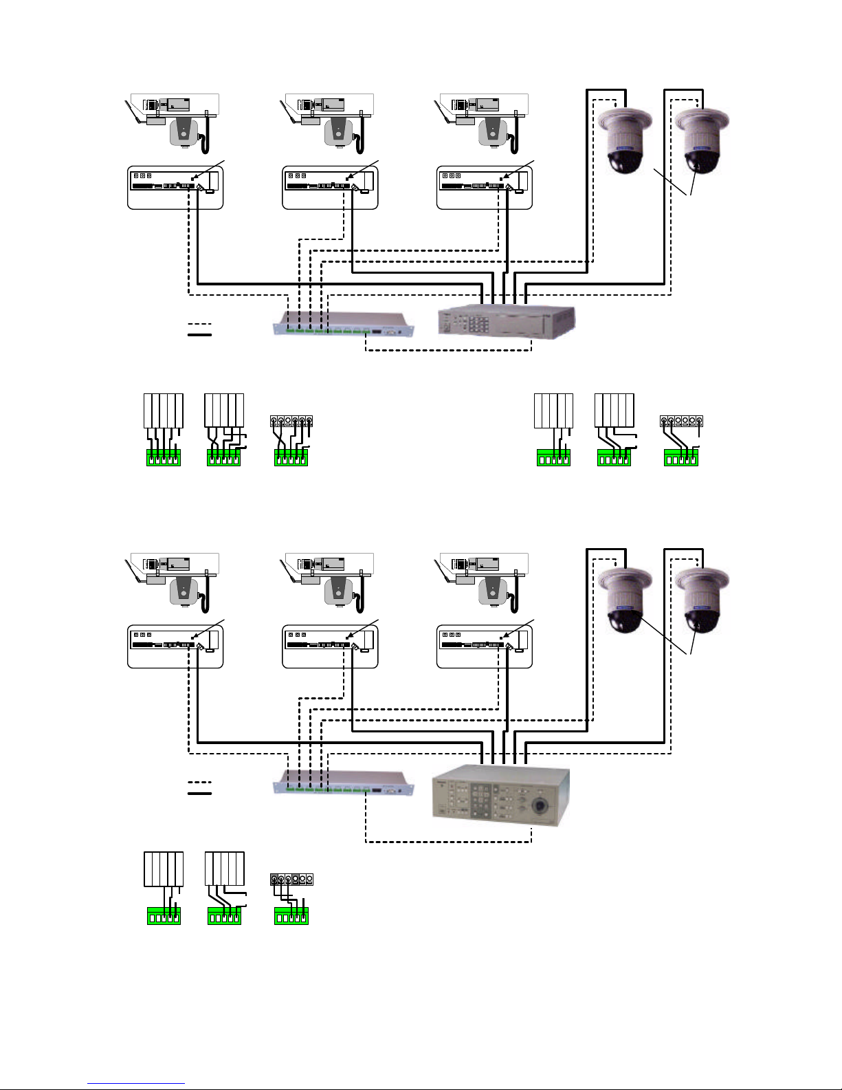
Camera 1 DC Head Camera 2 AC Head Camera 3 DC Head
Rx550 Address 1 Rx450 Address 2 Rx550 Address 3
Terminated Terminated Terminated
Terminated
SX350
BBV RS485 StarCard
Key
RS485
Coax
2 Wire connection details
RBR
A
T
R
A
T
R
B
G
N
D
DOME
R
E
D
O
R
A
N
G
E
G
R
E
E
N
Y
E
L
L
O
W
B
R
O
W
N
RBR
A
T
R
A
T
R
B
G
N
D
Rx450
Rx550
T
R
A
T
R
B
G
N
D
RAR
B
SCREEN
SCREEN
RBR
A
T
R
A
T
R
B
G
N
D
B
G
N
D
A B
G
N
D
A
SX350
StarCardStarCard StarCard
SCREEN
2 1
Panasonic SX-350
Wiring Details
The SX350 has two individual RS485 ports. Each port may be
connected to a seperate StarCard. The diagram on the left
shows a connection to port 2.
Camera 1 DC Head Camera 2 AC Head Camera 3 DC Head
Rx550 Address 1 Rx450 Address 2 Rx550 Address 3
Terminated Terminated Terminated
Terminated
FS616
BBV RS485 StarCard
Key
RS485
Coax
4 Wire connection details
RBRAT
R
A
T
R
B
G
N
D
DOME
R
E
D
O
R
A
N
G
E
G
R
E
E
N
Y
E
L
L
O
W
B
R
O
W
N
RBRAT
R
A
T
R
B
G
N
D
Rx450
Rx550
T
R
A
T
R
B
G
N
D
RAR
B
SCREEN
SCREEN
TBTARBR
A
RBRAT
R
A
T
R
B
G
N
D
SCREEN
FS616
StarCardStarCard StarCard
2 Wire connection details
RBRAT
R
A
T
R
B
G
N
D
DOME
R
E
D
O
R
A
N
G
E
G
R
E
E
N
Y
E
L
L
O
W
B
R
O
W
N
RBRAT
R
A
T
R
B
G
N
D
Rx450
Rx550
T
R
A
T
R
B
G
N
D
RAR
B
SCREEN
SCREEN
TBTARBR
A
RBRAT
R
A
T
R
B
G
N
D
SCREEN
FS616
StarCardStarCard StarCard
Panasonic FS-616
Wiring Details
Page 29
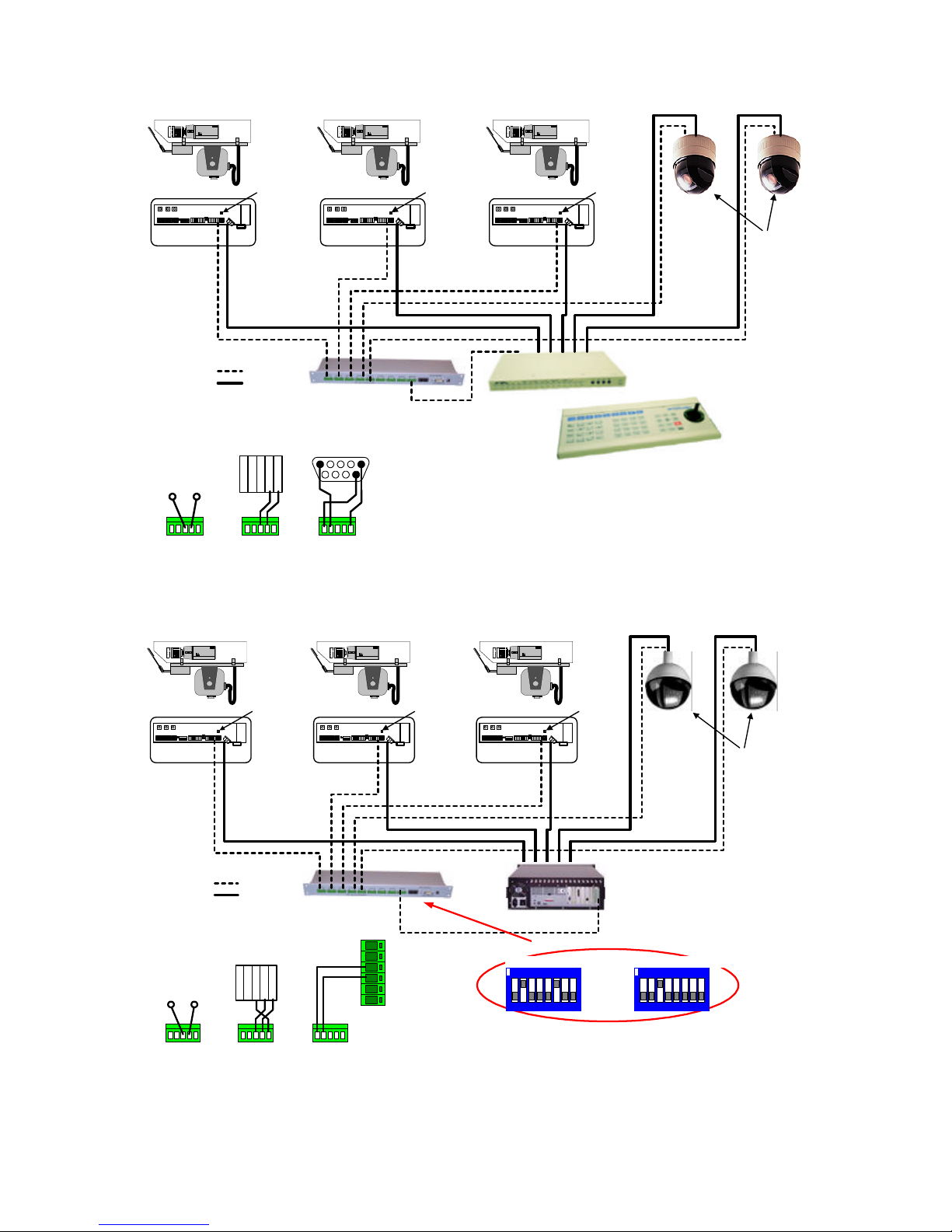
RS485 Star Card Manual V14 4Feb04.doc Page 29/29
Camera 1 DC Head Camera 2 AC Head Camera 3 DC Head
Rx552 Address 1 Rx452 Address 2 Rx552 Address 3
Terminated Terminated Terminated
Terminated
BBV RS485 StarCard
Key
RS485
Coax
RS485 connection details
(Star Card must be in 4 wire mode)
RBRAT
R
A
T
R
B
G
N
D
DOME
StarCard
RBRAT
R
A
T
R
B
G
N
D
StarCard
RBRAT
R
A
T
R
B
G
N
D
Rx452/552
T
R
A
T
R
B
G
N
D
RAR
B
StarCard
A
or
+
B
or
-
Starcard/Protocol converter when used with
Integral Technologies DVX
RX RX+
TX TX+
RLY
RLY
DVX RS485 PORT
Address 4 Address 5
1 2 3 4 5 6 7 8
ON
1 2 3 4 5 6 7 8
ON
SW1 - Pelco D, 2400,E,8,1 SW2 - VCL 9600,N,8,1
Protocol converter switch settings for VCL conversion.
IMPORTANT
Set each camera to Pelco Spectra II within the
DVX setup then set the StarCard protocol
converter SW1 switch as shown and SW2 to the
required dome protocol.
Camera 1 DC Head Camera 2 AC Head Camera 3 DC Head
Rx552 Address 1 Rx452 Address 2 Rx552 Address 3
Terminated Terminated Terminated
Terminated
BBV RS485 StarCard
Key
RS485
Coax
RS485 connection details
(Star Card must be in 4 wire mode)
RBRAT
R
A
T
R
B
G
N
D
DOME
StarCard
RBRAT
R
A
T
R
B
G
N
D
DM- DB9F
StarCard
RBRAT
R
A
T
R
B
G
N
D
Rx452/552
T
R
A
T
R
B
G
N
D
RAR
B
StarCard
A
or
+
B
or
-
DM Digital Sprite/DSL/DS2 RS485 Wiring details
Ground must be connected with DS2
54321
6 7 8 9
 Loading...