

Page 1
Building Block Video Ltd
17 Apex Park,
Diplocks Industrial Estate,
Hailsham, East Sussex, BN27 3JU, UK
Tel: + 44 (0) 1323 842727
Fax: +44 (0) 1323 842728
www.bbvcctv.com
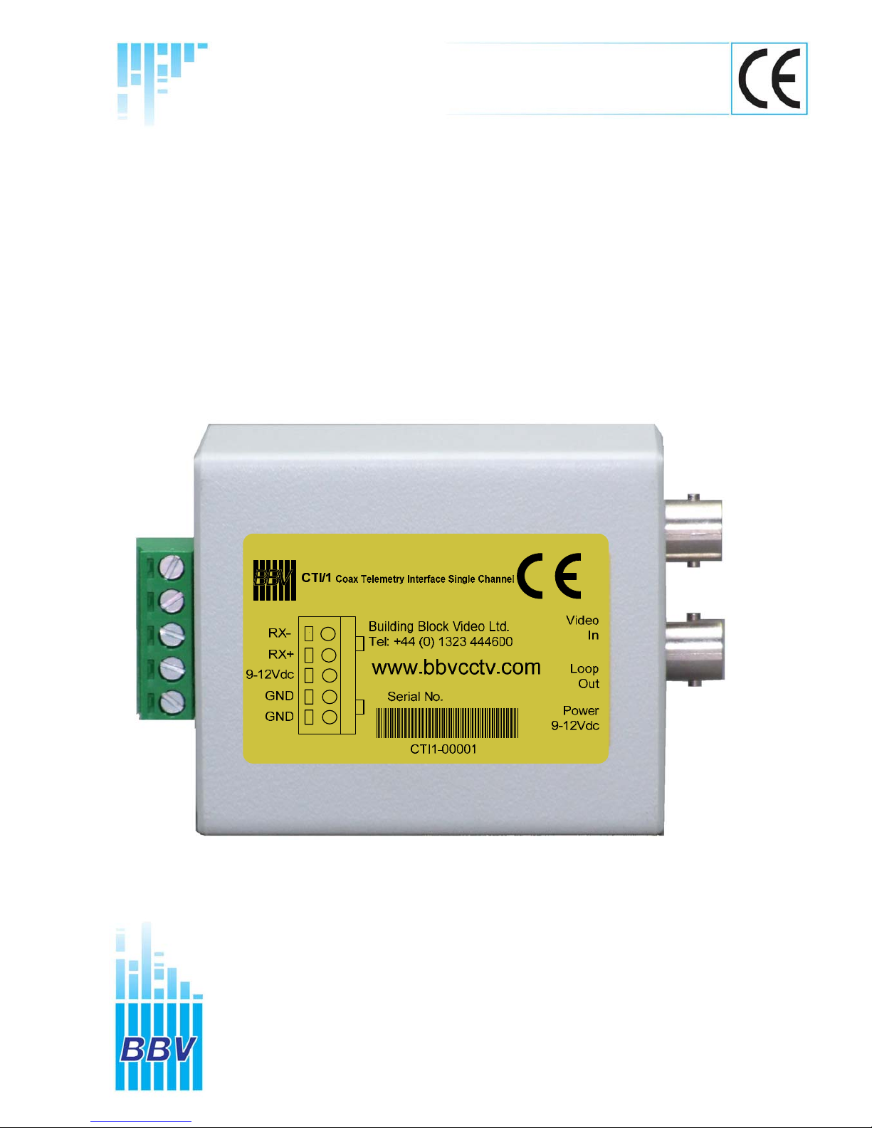
CTI/1
RS422/BBV Coax Telemetry Interface Single Channel
Installation
Guide
Page 2

CTI 1 Manual V2 Aug 11
2
Page 3

CTI 1 Manual V2 Aug 11
3
Contents
Introduction Page 4 Address Setting Procedure Page 8
Pre – Installation Checks Page 5 Function Command Table Page 8
Technical Specification Page 6 Example System Drawing Page 9
Software Version History Page 6 Test Mode Page 10
Connection Diagram Page 7
Page 4

CTI 1 Manual V2 Aug 11
4
INTRODUCTION
GENERAL
The CTI/1 is designed to provide conversion from RS422/485 serial telemetry to
BBV Coax Telemetry based systems.
Up the Coax telemetry allows upgrading of static cameras to PTZ without the
need for additional cabling.
The RS422/485 input is auto detecting. The CTI/1 will understand BBV RS422 &
Pelco P @ 9600, N, 8, 1.
1 x BNC output provides Coax Telemetry, connecting to a single receiver.
1 x BNC output provides Video Loop Through.
Each unit is supplied with a 12Vdc Power Supply, Manual & Adhesive Fixings.
Please Note: The CTI/1 supports eight addresses only
Protocols supported are: BBV & Pelco P
The CTI/1 has been tested with the BBV FBM Matrix, BBV TX1500 Matrix, BBV
TX400DC/RS485 and a number of products that transmit Pelco P 9600 N81,
BBV ALWAYS RECOMMENDS THAT ALL SYSTEMS
ARE BENCH TESTED BEFORE INSTALLATION
Page 5

CTI 1 Manual V2 Aug 11
5
PRE-INSTALLATION CHECKS AND SAFETY PROCEDURES
Unpacking - Inspect the packaging for signs of damage. If damage has occurred, advise the
carrier and/or the suppliers immediately. Unpack the receiver carefully and check that all the
items are present and correct (see checklist on box). If any item is missing contact the supplier.
Part
number
Description
9-12Vdc
PSU
1 x 5 Way
Green IMO
(5.08 mm pitch)
Jumper Link on
pin 5 only /J3
Manual
2 x Sticky
Pads
Warranty
card
CTI/1
RS422/BBV Coax Telemetry
Interface single channel
X X X X X X
Retain Packaging - The shipping carton is the safest container in which to transport the unit.
Retain undamaged packaging for possible future use.
IMPORTANT SAFETY PRECAUTIONS
Read & Retain Instructions - All relevant safety, installation and operating instructions should
be read & retained before attempting to install, connect or operate the unit.
Water and Moisture - Do not expose the internal electronics of this unit to water or dampness.
Power Sources - This unit should be operated only from the supplied power supply.
Servicing - Servicing of the unit should only be undertaken by qualified service personnel.
Damage Requiring Service - Servicing by qualified personnel should be carried out under the
following conditions:
(a) When the power-supply cord or plug is damaged;
(b) If liquid has been spilled, or objects have fallen into, the unit;
(c) If the internal electronics of the unit have been exposed to rain or water;
(d) If the unit does not operate normally by following the operating instructions.
(e) If the unit has been dropped or the enclosure is damaged;
Replacement Parts - If replacement parts are required, ensure that only replacement parts
recommended by the product manufacturer are used.
Safety Check - Upon completion of any service or repairs to the unit, safety checks should be
performed to ensure that the unit is in proper operating condition.
Coax Grounding - If an outside cable system is connected to the unit, be sure the cable
system is grounded.
Pre-installation Checks - It is recommended that the unit be bench-tested prior to installation
on the site.
Adhere to Safety Standards - All normal safety precautions as laid down by British Standards
and the Health and Safety at Work Act should be observed.
WARNING
TO PREVENT DANGER OF FIRE OR SHOCK, DO NOT EXPOSE THE INTERNAL
COMPONENTS OF THIS EQUIPMENT TO RAIN OR MOISTURE.
Page 6

CTI 1 Manual V2 Aug 11
6
Technical Specification
Power Requirements 9-12Vdc 500mA
Inputs BBV RS422 or Pelco P 2 Wire RS485 or 2 Wire RS422 Simplex via
5 pin Green Screw Terminal Connector
Maximum Cable Distance Belden 8723 = 1200mtrs
Outputs 1 x BBV Coax Telemetry via BNC Connectors
Minimum Cable distance = 5mtrs
Maximum Cable Distance RG59 = 250mtrs
CT125 = 500mtrs
Facilities Supports 8 addresses
LED as power & address valid data
LED Coax telemetry active
TEST SWITCH sends a command to the
camera or receiver.
Boxed Dimensions. Length 69mm
Width 57mm
Height 36mm
Weight 64 grams
CTI/1 Software Version History
Version 1 December 2008
1. CTI/1 Released
Support of BBV, Pelco P RS485 input protocols converting to BBV Coax output protocol
Version 5 August 2011 1. Added test button function.
When the push button is pressed the CTI1 outputs pan right speed 7 command and stop on release.
Page 7
BBV
COAX TX
REG1
PCB08007 ISS2
J3
www.bbvcctv.com
PWR
SW1
X1
TV1
J1
J2
TF2
J3
Video Out
to transmitter
Video In
from cam era
Video in
Video In
from camera
Video out
Supply
9-12Vdc
RX
-
RX+
9-12Vdc
GND
GND
Test sw.
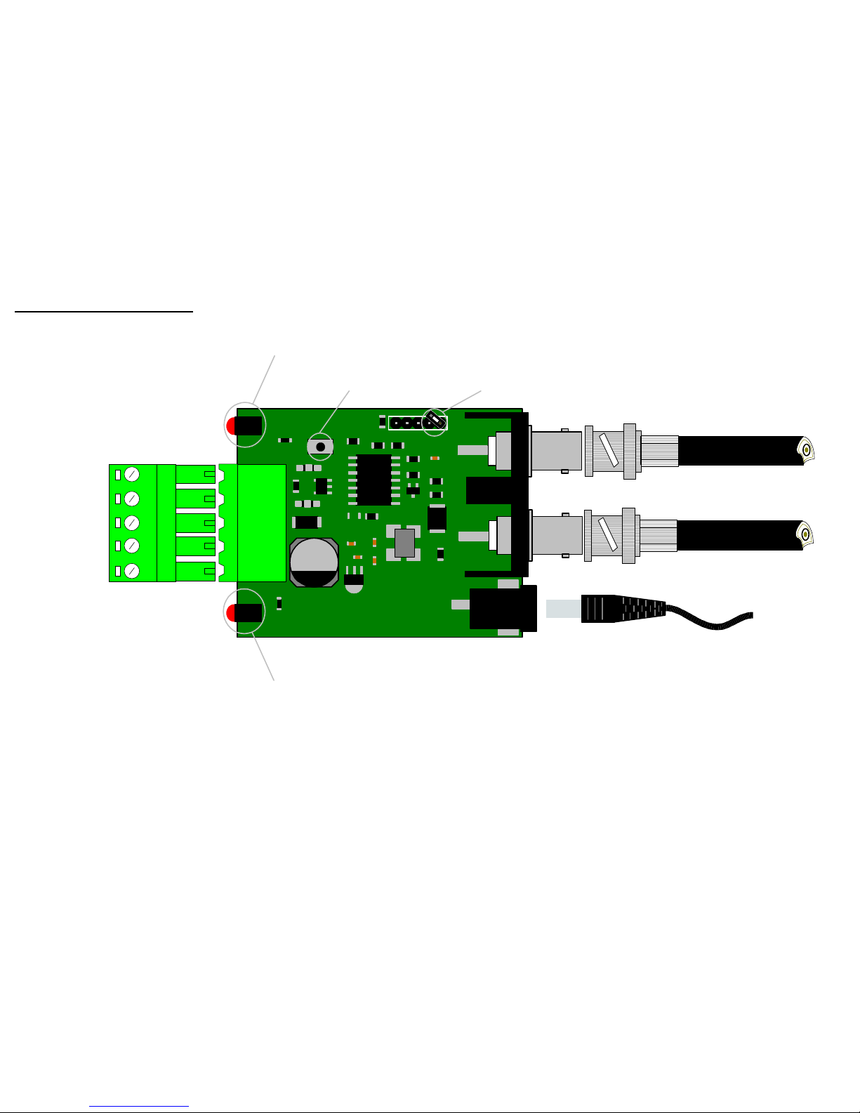
Power & valid address data LED
Coax telemetry active LED
In normal operation the Power LED is ON, when receiving valid serial telemetry the LED flashes OFF & the telemetry active LED will flash ON.
CTI 1 Manual V2 Aug 11
7
CTI/1 Connection Diagram
Page 8
CTI 1 Manual V2 Aug 11 8
Address Setting Procedure
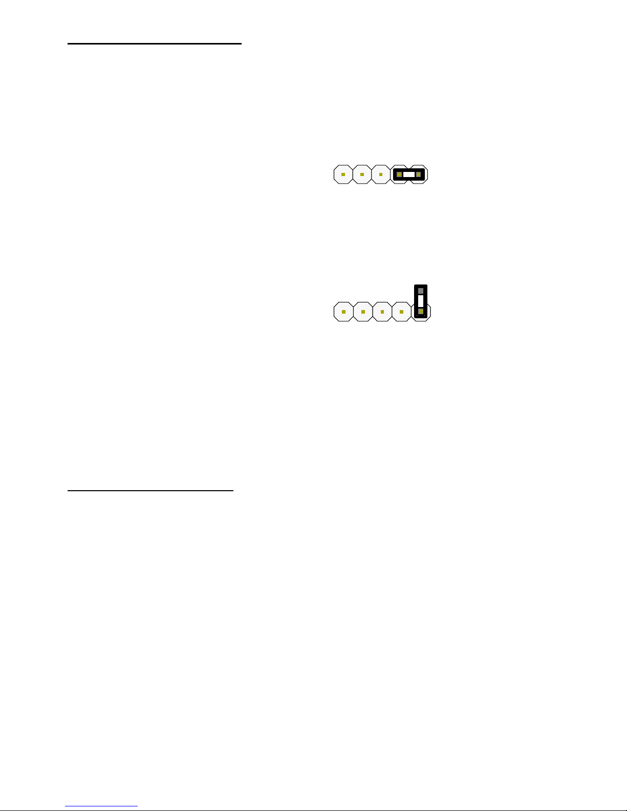
The CTI/1 is defaulted to address 1, to set a new address follow the steps below:
Step Action
1 Remove Power and Plastic Cover
2 Fit Jumper Link to J3 Pins 4 & 5
3 Apply Power
4
Press & Hold SW1 Address Button until the Power LED flashes the required number of
times to match the address. (1 – 8 Flashes followed by longer pause)
5 Remove Jumper on J3Link
6 Remove Power
7 Refit Plastic Cover & Re-apply Power
Function Command Table
BBV support a number of commands that are referred to as # commands these are used to enter the menu of
the camera or receiver. In addition BBV coax telemetry also supports 2 preset patrols & an Autopan command,
all of the fore-mentioned commands can be called from preset commands these are all listed below.
BBV Coax Output BBV RS422 Pelco P 9600 N 8 1
1# 1# Save Preset 95 or Goto Preset 61
2# 2# Goto Preset 33 or Goto Preset 62
3# 3# Goto Preset 94 or Goto Preset 63
4# 4# Goto Preset 34 or Goto Preset 64
Start Patrol 1 Start Patrol 1 Goto Preset 97 or Goto Preset 66
Start Patrol 2 Start Patrol 2 Goto Preset 98 or Goto Preset 67
Autopan Autopan Goto Preset 99 or Goto Preset 68
Page 9
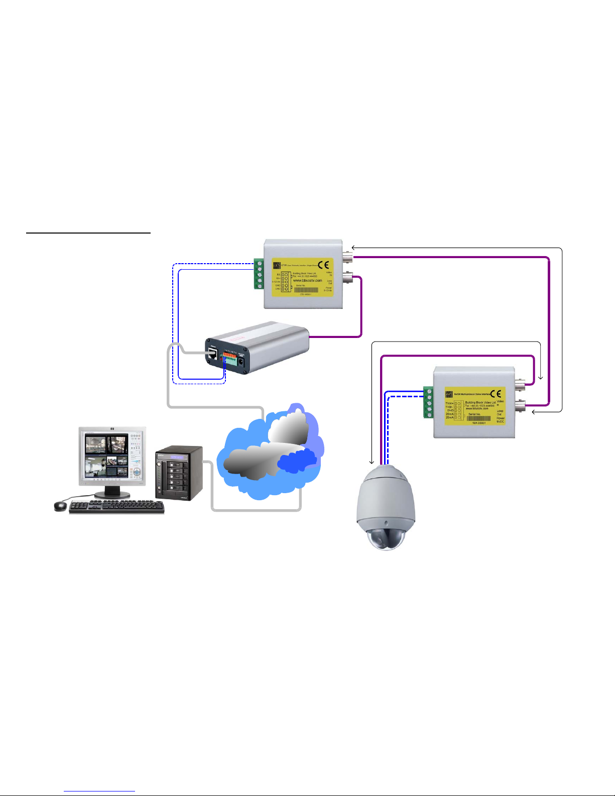
Example System Drawing
CTI/1
RX10X
IP ENCODER
NVR SYSTEM
UNDEFINED
DOME
up to 250m RG59
up to 500m CT125
up to 5m RG59
BBV RS422 or Pelco P
9600 N81Protocol
CTI 1 Manual V2 Aug 11
9
Page 10
al V2 Aug 11
10
Test Mode
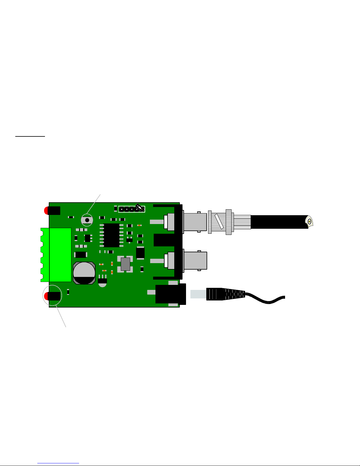
There will be occasions where it will be necessary to test if the CTI/1 is sending coax telemetry to the camera or receiver
connected to the remote end of the coax. As you will see from the drawing below only one coax is needed to be connected.
This is the coax from the camera or receiver. The test can be done by simply pressing the push switch marked as SW1 on
the PCB. When the switch is pressed the camera or receiver will receive a pan right a half speed, on release of the switch a
stop will be sent. It is important to remember that if the camera or receiver is fully zoomed it may reduce the overall pan
speed.
BBV
COAX TX
REG1
PCB08007 ISS2
J3
www.bbvcctv.com
PWR
SW1
X1
TV1
J1
J2
TF2
Video Out
to transmitter
Video In
from c amera
Video in
Supply
9-12Vdc
Test sw.
Coax telemetry active LED
CTI 1 Manu
Page 11

CTI 1 Manual V2 Aug 11 11
Page 12
Extend your BBV Warranty from 12 months to 3 years
As of the 1
s
t
September 2008 BBV have offered our
customers the opportunity to extend the standard 12
month warranty to 3 years.
You must register for the extended warranty within 12
months of the date of manufacture.
How to register for the 3 year warranty
Registering for the new, longer 3 year warranty term is
quick and easy.
Either:
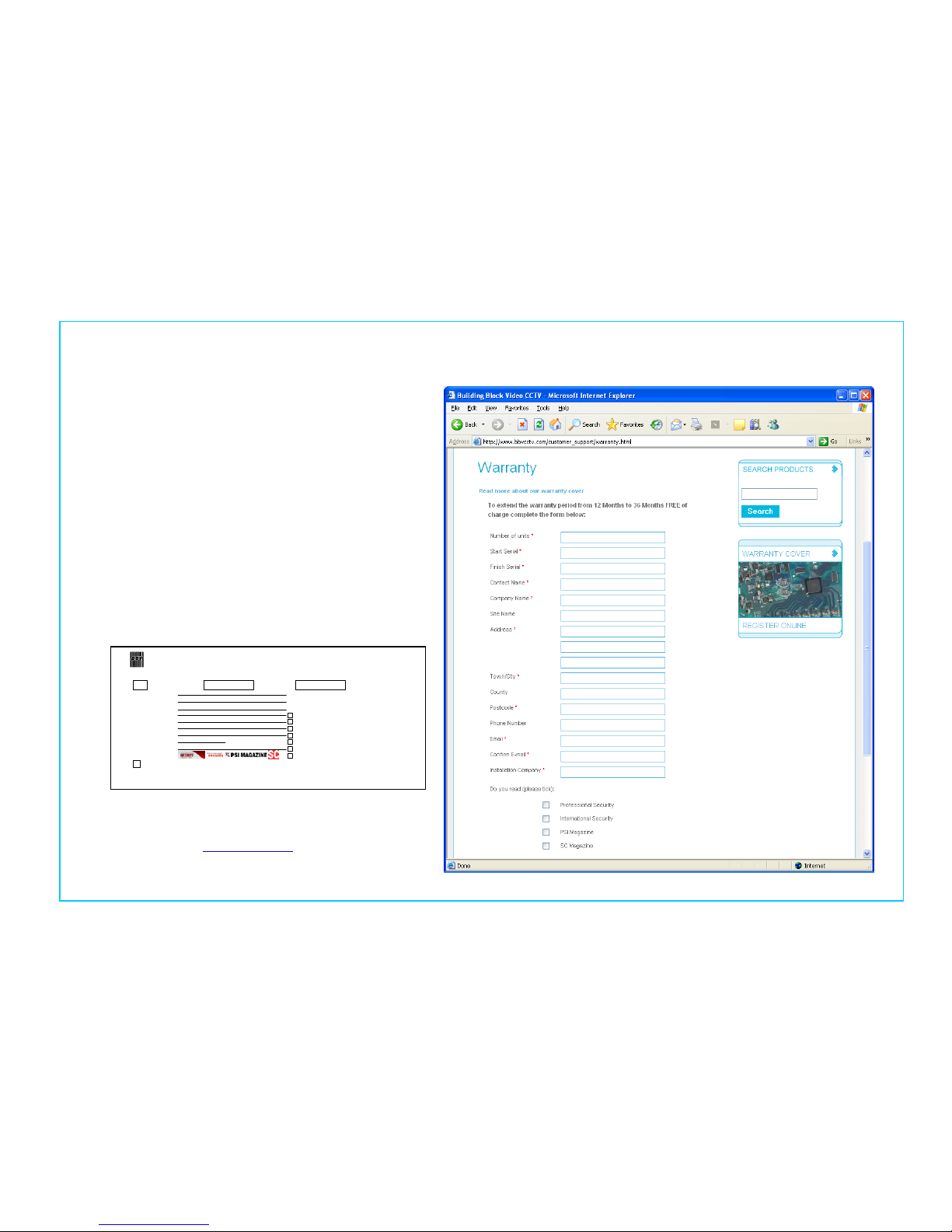
Complete the warranty application card that comes in the
box with your BBV product, and return it FREEPOST to
BBV:
VAT Reg. No. 621758439 Registered in England No. 2852921 Registered office: 17 Apex Park Diplocks Way Hailsham East Sussex UK BN27 3JU
If this card is returned with the serial number of the product and the Installation company
details BBV will extend the warranty period from 12 Months to 36 Months.
I do not require any other further product information,
BBV 3 Year Warranty
Please could you send me inform ation
especially on:
Rx100s
Rx45x & Rx55x
FBM Video Matrices
Tx1500 Video Matrices
Starcard & Starcard Converters
BBV Quad
Pick A Point
Please refer to WWW.BBV CCTV.COM for terms, cond itions & exclusions
Contact Name.
Company Name.
Phone Number.
Site Name.
Address 1.
Address 2.
Address 3.
e-mail address.
Post Code.
Do you read.
Number of Units, Start Serial No. Final Serial No.
Or alternatively:
Register online at:
www.bbvcctv.com
Simply enter your details on the ‘Warranty Cover’ page.
 Loading...