

Page 1
INSTRUCTION MANUAL
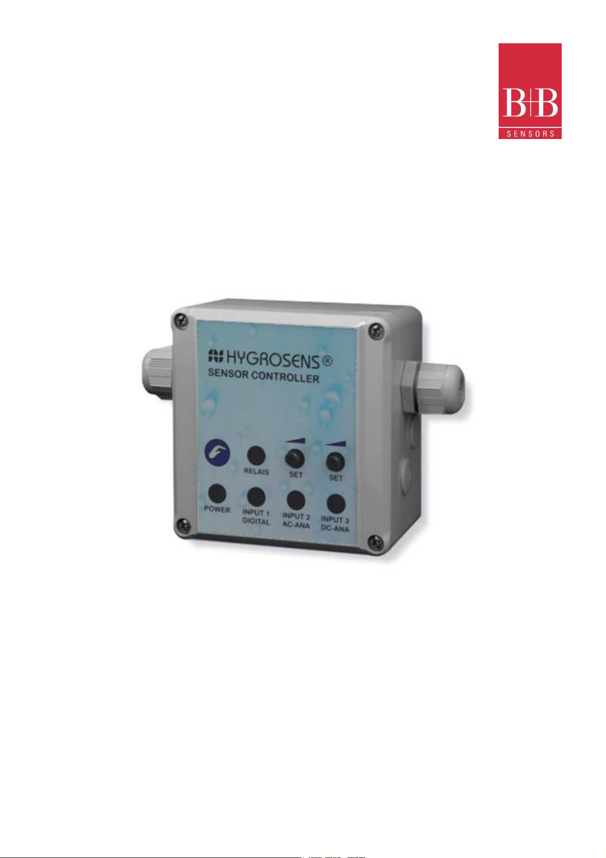
Universal sensor switching module
230 V version with Housing
0141 0316-142 September 2011
Technical changes reserved
Fon +49 771 83160 | Fax +49 771 831650 | info@bb-sensors.com | bb-sensors.com 1 / 17
B+B Thermo-Technik GmbH | Heinrich-Hertz-Str. 4 | D-78166 Donaueschingen
Page 2

INSTRUCTION MANUAL
Universal sensor switching module
230 V version with Housing
Contents
1. General dangers and precautions 3
1.1. Instructions regarding documentation 3
1.2. Safety instructions 3
2. Description 4
2.1.Functional description 4
2.2. Range of available probes 5
2.2.1. Humidity probe 5
2.2.2. Conductance probe 5
2.2.3. Light intensity probe 5
3. Technical data 6
4. Ordering information 6
5. Assembly, adjustment and configuration 7
5.1. Electrical connection 7
5.1.1. Safety instructions 7
5.1.2. Probes 7
5.2. Configuration 7
5.3. Adjustment of switching point 7
5.4. Adjustment of time delay 7
5.4.1. Operating voltage 8
5.4.2. Load circuit 8
6. Technical appendix 9
6.1. General instructions 9
6.2. Switching input 9
6.3. Impedance input 11
6.4. Analog input 13
6.5. Time delay switch 16
6.6. Relay 16
7. Guarantee 17
7.1. Repair and calibration service 17
0141 0316-142 September 2011
Technical changes reserved
Fon +49 771 83160 | Fax +49 771 831650 | info@bb-sensors.com | bb-sensors.com 2 / 17
B+B Thermo-Technik GmbH | Heinrich-Hertz-Str. 4 | D-78166 Donaueschingen
Page 3
INSTRUCTION MANUAL
Please carefully read the following instructions before putting into operation! The symbols used in the operating manual are
to
This symbol indicates likely danger for persons, material or environment. The information provided in the
associated text should
This symbol refers to important application notes and tips, which are necessary for successful working and should to be
Universal sensor switching module
230 V version with Housing
1. General dangers and precautions
1.1. Instructions regarding documentation
make you careful, before hand, regarding safety considerations and dangers. But all these symbols cannot substitute the text of
the associated safety instructions in any way. Therefore, the instructions should also be always read completely!
be duly followed to avoid any kind of risk.
absolutely followed to ensure good results.
1.2. Safety instructions
Please read these instructions, carefully and completely, before putting the device into operation. Please also comply and follow the safety
instructions, specially the safety regulations related to the devices being operated on mains supply.
The product should be installed and used only for the intended applications as described in these instructions. Any other application is not
advised and shall lead to loss of guarantee and exclusion from liability. This also applies to any changes or other modifications carried out on
the device by the user.
Defective safety devices should be replaced with same type of items in respect of trip current rating, tripping characteristics, and mechanical
fitment dimensions. Bypassing protections lead to a considerable safety risk and are not allowed under any circumstances.
The connection terminals can be wired to mains voltage. Contact with live parts lead to fatal dangers. The mounting and maintenance
operations should be carried out by only trained personnel, who are authorised on the basis of technical training in this field. The applicable
safety regulations should be followed. The switching device must be assembled in a switchgear cabinet or a fully closed plastic housing.
Mounting and servicing operation should be carried out only after switching off the voltage.
The product is not meant for controlling electrical systems, which perform safety related functions. In normal operation also, there is always a
danger of malfunctioning due to failure of any component or any other disturbance. The user has to ensure that there are no consequential
damages due to malfunctioning or undefined switching status of the relay. This is all the more possible, if heavy loads like heaters or motors
are triggered with the relays.
0141 0316-142 September 2011
Technical changes reserved
Fon +49 771 83160 | Fax +49 771 831650 | info@bb-sensors.com | bb-sensors.com 3 / 17
B+B Thermo-Technik GmbH | Heinrich-Hertz-Str. 4 | D-78166 Donaueschingen
Page 4

INSTRUCTION MANUAL
Universal sensor switching module
230 V version with Housing
2. Description
2.1. Functional description
The universal sensor-switching module is suitable as a two-point regulator for a wide variety of sensors and industrial probes. A suitable
sensor is connected at the input for sensing the parameter which is to be regulated. The relay mounted on the PCB gets triggered as per
limit settings done through a potentiometer.
For universal application, the device is provided with three different types of inputs, which are internally connected and can be used
individually or together:
• Input 1: A Schmitt-trigger input with high pass filter for switching sensors like Reed-contacts, alarm-circuits, pushbuttons, light barriers,
message contacts or motion alarm unit. Switch contacts, Open-collector outputs or sensors with binary voltage output 0/5 V can also be
connected at the input.
• Input 2: An AC-input for analog AC voltage impedance evaluation. This input is specifically meant for electrolytic sensors like
conductance probes and level indicators, humidity and dew formation sensors or water/leakage probes.
• Input 3: An universal, analog voltage or resistance input and also for industrial voltage and current signals (0..1 V/5 V/10 V, 0..20 mA,
etc.). This is also suitable for direct connection of resistive sensors like LDRs, NTCs or PTCs.
The three inputs can be used either separately or in combined form (i.e. internally wired or joined). The switching behaviour (active relay with
upper and lower limits) of each input can be separately configured with its relevant jumper connection.
The three inputs are brought out through the RJ12 socket, to which standard probes, which are available as accessories can be connected
or joined through soldering without much expenses. The voltage and resistance input (Input 3) is also additionally brought out through a 3pin terminal strip.
In addition, the device is provided with a time delay switch, which can be configured over a wide range (approx. 10 sec to 10 min). It is
digitally configured with the help of a jumper connection.
The adjustment of limiting values and Hysteresis is done with three potentiometers. The condition of device is displayed with a total of 6
LEDs.
The high rating relay has a changeover contact. The NO contact of the relay can switch a load up to 230 V/5 A and is provided with a
varistor for surge suppression.
Scope of supply
The scope of supply is without probe. Standard probes are available as accessories. The scope of supply of 12 V/24 V model is in the form
of a PCB of size 95 x 75 mm without housing and operating panel.
The 230 V model is supplied in a housing (100 x 100 x 60 mm) with integrated power supply unit and operating panel.
0141 0316-142 September 2011
Technical changes reserved
Fon +49 771 83160 | Fax +49 771 831650 | info@bb-sensors.com | bb-sensors.com 4 / 17
B+B Thermo-Technik GmbH | Heinrich-Hertz-Str. 4 | D-78166 Donaueschingen
Page 5

INSTRUCTION MANUAL
Universal sensor switching module
230 V version with Housing
2.2. Range of available probes
The probes described below are available as accessories. The probe is provided with a 1 m long connection cable, PG-threads for mounting
of housing and a ready made RJ12 plug connector. All commercial grade industrial probes with voltage and current output can also be
operated with the device.
2.2.1. Humidity probe
The measuring probe is meant for regulation of relative humidity in green houses, fields, sanitary rooms, and switchgear cabinets. The
integrated electrolytic humidity sensor inside the probe is protected with a hydrophobic sinter cap. The measuring range is right from 35..90
% RH and is not temperature compensated.
2.2.2. Conductance probe
The conductance probe is intended for monitoring of water quality (ion content), as a level switch or as a foam sensor. Measuring range is
right from approx. 10µS…30µS.
2.2.3. Light intensity probe
The weatherproof light intensity probe is suitable for both indoor and outdoor applications. The measuring range is right from 50..20000 Lux.
Typical areas of application are twilight switches or emergency lights.
0141 0316-142 September 2011
Technical changes reserved
Fon +49 771 83160 | Fax +49 771 831650 | info@bb-sensors.com | bb-sensors.com 5 / 17
B+B Thermo-Technik GmbH | Heinrich-Hertz-Str. 4 | D-78166 Donaueschingen
Page 6

INSTRUCTION MANUAL
General
Operating voltage
230 VAC/5 VA max.
Operating voltage
12 V..15 V DC 65 mA max.
Operating voltage
22 V..28 V DC 45 mA max.
Time delay switch
10 sec to 11 min +/
-
20%
Relay
Changeover contact for resistive load
Surge suppression
Suppression with a Varistor VZ 05/390V
Dimensions
Type –
230 V (156530)
100 x 100 x 60mm
Sensors
DC
Impedance input
0..1/10/100 k
Ohm; configurable with jumper plugs
Voltage/Current input
0..1 V/10 V/20 mA, configurable with jumper plugs
AC Impedance input
Series impedance
10
k..50 k
Switching input
NC/NO or voltage signal 0/5
V
Swiching device an accessories
Ordering No.
Universal Switching module, PCB for 12 V DC
SENSW
-
MOD12V
Universal Switching module, PCB for 24 V DC
SENSW
-
MOD24V
Switching module 230V, in housing with operating panel
SENSW
-
GEH230V
Housing ET210F, unfinished
0209 0014
Probe with connection cable
Ordering No.
Conductance probe
SENSW
-
LWF
Space humidity probe
SENSW
-
RFF
Light intensity probe, weather proof
SENSW
-
LIF
Our delivery program is constantly updated. If
you require any special type of probe, please do send
your enquiry to us!
Universal sensor switching module
230 V version with Housing
3. Technical data
Type –230V (156530)
Type –MOD12V (156503)
Type –MOD24V (156517)
4. Ordering information
11 V..14 V AC 80 mA max. (without probe)
15 V..25 V AC 60 mA max. (without probe)
configurable with jumper plugs
NO contact rating 230V AC / 5A
NC contact rating 230V AC /2 A
Supply in plastic housing
Type –MOD (156503/17) PCB 95 x 75 x 30mm
Supply only as a PCB
Conductance 30µS..10 µS
0141 0316-142 September 2011
Technical changes reserved
Fon +49 771 83160 | Fax +49 771 831650 | info@bb-sensors.com | bb-sensors.com 6 / 17
B+B Thermo-Technik GmbH | Heinrich-Hertz-Str. 4 | D-78166 Donaueschingen
Page 7

INSTRUCTION MANUAL
Universal sensor switching module
230 V version with Housing
5. Assembly, adjustment and configuration
5.1. Electrical connection
5.1.1. Safety instructions
Caution! Touching the high voltage parts may lead to fatal dangers. The mounting and maintenance operations should be carried out by only
trained personnel, who are authorized on the basis of technical training in this field. The applicable safety regulations are to be duly followed!
The switching device must be assembled in a switchgear cabinet or in a fully closed plastic housing. Mounting and servicing work should be
carried out only after switching off the voltage.
Due to wrong tightening of screws of the connection terminals or by use of inappropriate tool, the terminals can get damaged because of
which the insulation or the contact can get disturbed. Badly connected leads can come out during operation and cause a serious risk to
safety. Due to contact resistance at terminal connections, there can be increased heat generation which can cause fire. Wrongly wired
connections can destroy electric components and cause other damages.
5.1.2.Probes
The RJ12-plug connectors are meant for direct connection of probe. The plug connector is brought out through the hole in the housing and is
properly secured by the PG7 gland. The connection of ready made probe is to be carried out as per enclosed data sheet. While connecting
the probes, care should be taken to use the correct connection socket. The sockets are not coded and can get mixed up. The probe can get
damaged due to wrong connection.
5.2. Configuration
The connector configuration of ready made probe can be seen from the data sheet of probe.
The switching behaviour of the device is decided by the jumper connections below the input socket. The switching status of the device can
be observed at the light emitting diode(LED). In active condition (=Relay closed) the LED glows.
Since the three inputs of the module are connected through “OR” logic, the jumper plugs "Switching polarity" of the other two unused inputs
should be kept in unwired inactive position (see sketch). The associated LEDs under the unused input sockets will not glow. If this is not
ensured, the relay will be always put on.
5.3. Adjustment of switching point
The adjustment of switching point is done as per probe type either by the trim potentiometer for impedance input (“SETP IMP”) or for analog
input (“SETP ANA”). For the analog input, the hysteresis can also be adjusted at the potentiometer ("HYS ANA"). Further instructions about
adjustment can be obtained from the data sheet of probe.
5.4. Adjustment of time delay
The configuration of time delay time is done by keeping the jumper plugs in the terminal strip "TIMER" at the desired position. It must be set
by only one bridge.
0141 0316-142 September 2011
Technical changes reserved
Fon +49 771 83160 | Fax +49 771 831650 | info@bb-sensors.com | bb-sensors.com 7 / 17
B+B Thermo-Technik GmbH | Heinrich-Hertz-Str. 4 | D-78166 Donaueschingen
Page 8

INSTRUCTION MANUAL
Universal sensor switching module
230 V version with Housing
5.4.1. Operating voltage
12V/24V-AC/DC Model: The operating voltage is connected at the
terminals “SUPPLY VOLTAGE“. The rating of nominal voltage is
mentioned on the PCB, under the voltage connection and also on
the relay and must be maintained as per specifications on the data
sheet in order to ensure an error free functioning. A too high
operating voltage can lead to damage of the device. Extremely low
or unstable operating voltage leads to malfunctioning.
230V AC model:
The connection with mains power supply should be done by only
trained and authorized persons. The electrical connection is done
through the 6-pin plug connector as per pin configuration. The
device can be operated only with 230V AC supply.
5.4.2. Load circuit
The safety of load circuit, if required, should be taken care of
through some external protection arrangement. (max. 5 A). To
switch higher currents, corresponding switching elements should be
used.
The changeover contacts of both the relays are potential free and
are terminated at the connection socket. The connection to load is
done as per the connector configuration. The NO contact of the
relay is provided with a 390 V varistor for surge suppression.
0141 0316-142 September 2011
Technical changes reserved
Fon +49 771 83160 | Fax +49 771 831650 | info@bb-sensors.com | bb-sensors.com 8 / 17
B+B Thermo-Technik GmbH | Heinrich-Hertz-Str. 4 | D-78166 Donaueschingen
Page 9

INSTRUCTION MANUAL
Universal sensor switching module
230 V version with Housing
6. Technical appendix
6.1. General instructions
The technical appendix is useful for persons with adequate knowledge of electronics. The applicable safety regulations shall be duly
followed! Connection and mounting work shall be carried out only after switching off the voltage supply.
The following instructions help in connection of your own probes at the input socket of module. However, this certainly needs necessary
attention, as different operating voltages are present at the socket also. Sometimes, wrong connection may lead to damage of the
components or result in failure of the module itself.
In the following description, the three inputs have been explained separately as these are also functionally independent of each other. Since
the inputs are “OR” connected before the time delay switch, the jumper plug "Switching polarity" of the other two unused inputs must be
plugged in the inactive position. The LEDs below the unused input sockets may not glow.
Touching the electronic components in switched off condition is also to be avoided. Electronic components can get damaged due to
electrostatic discharge process. ESD protection measures should be duly observed!
6.2. Switching input
Circuit diagram
Functional description
The switching input is meant for connection of all switching sensors like REED-switch or contacts. The contact is connected at the RJ12 plug
connector from GND (pin 2,5 or 6) to INPUT (pin 3).
As soon as the contact opens, the input level goes to high through the internal pull-up resistance. The Schmitt trigger is directed towards the
high pass filter and transient protection. The switching point of Schmitt-Trigger lies at approx. 1.5 V (low) and 3.5 V (high). The switching
polarity can be selected by the jumper connections at the output of two series connected invertors. The signal triggers the internal timer,
which in turn switches on the relay at the output stage. The switching status of output is indicated by LED.
0141 0316-142 September 2011
Technical changes reserved
Fon +49 771 83160 | Fax +49 771 831650 | info@bb-sensors.com | bb-sensors.com 9 / 17
B+B Thermo-Technik GmbH | Heinrich-Hertz-Str. 4 | D-78166 Donaueschingen
Page 10

INSTRUCTION MANUAL
Pin Function
Description
1 +5 V Operating voltage 5
V,
2 GND Device ground
3 INPUT
Input (Switch contact)
4 +12..24
V
Operating voltage 12...24
V,
5 GND Device ground
6 GND Device ground
View of contacts on the plug!
Universal sensor switching module
230 V version with Housing
Configuration of switching input socket (RJ12)
stabilized
not stabilized
Adjustment and configuration
In switching input, only switching polarity can be configured. In the right position, the NC contact of the relay is triggered. In the left position,
the switch mode is reversed, that means the NO contact of the relay is triggered.
Operating voltage connection
An operating voltage of 5V is available at pin 1 of RJ12 socket to feed supply to external switching amplifiers. The voltage is stabilised and
short circuit protected conforming to specification for integrated voltage regulators 78L05. The maximum current output should not exceed
10 mA in total. Applying external voltage leads to damage of components!
A rectified DC operating voltage is available at pin 4 of RJ12 socket to feed supply to external components. This voltage is between 12 V
and 30 V DC depending upon the model and supply voltage at input. The supply is unstabilised and without short circuit protection. The
maximum current output should not exceed 25 mA in total.
0141 0316-142 September 2011
Technical changes reserved
Fon +49 771 83160 | Fax +49 771 831650 | info@bb-sensors.com | bb-sensors.com 10 / 17
B+B Thermo-Technik GmbH | Heinrich-Hertz-Str. 4 | D-78166 Donaueschingen
Page 11

INSTRUCTION MANUAL
Universal sensor switching module
230 V version with Housing
6.3. Impedance input
Circuit diagram
Functional description
The impedance input is especially suitable for electrolytic type of sensors like conductance probes and level indicators, foam sensor,
humidity and dew formation sensors, material moisture content probe or water/leakage probe. The operating principle is based on an AC
voltage measurement that prevents the measuring current from creating electrochemical effects.
The evaluation is done based on the series impedance of a sensor which is connected between AC OUT and SENS IN terminals, or by the
parallel impedance of a probe (e.g. an interdigital structure) connected between SENS IN and CAP GND terminals. In such a case, a
resistance of 0.47 k is inserted between the AC OUT and SENS IN terminals.
The RC-oscillator generates a rectangular voltage waveform of approx. 3 kHz frequency. The measuring current is integrated over the RCnetwork through the preset potentiometer and the sensor placed in series (between AC OUT and SENS IN), and the saw tooth voltage
waveform is evaluated at the capacitor. The discriminator controls the overshooting of specified signal amplitude at the integrator of Schmitttrigger and both the inverters.
The switching polarity can be selected by the jumper connections at the output of two series connected inverters. The signal triggers the
internal Timer, which in turn switches the relay at the output stage. The switching status of output is indicated over the LED.
A fixed resistance (approx. 0.47 k ohm) is placed instead of the sensor as a conductance switch between AC OUT and SENS IN. In such a
case, the sensor is connected between SENS IN and CAP GND terminals and modulated through the capacitive leakage current of signal
amplitude. This type of operation is ideal for conductance measurement in liquids or for detecting presence of water.
0141 0316-142 September 2011
Technical changes reserved
Fon +49 771 83160 | Fax +49 771 831650 | info@bb-sensors.com | bb-sensors.com 11 / 17
B+B Thermo-Technik GmbH | Heinrich-Hertz-Str. 4 | D-78166 Donaueschingen
Page 12

INSTRUCTION MANUAL
Pin Function
Description
1 +12..24
V
Operating voltage 12..24
V
2 AC OUT
AC output
3 CAP GND
Capacitive ground
4 SENS IN
Evaluation input
5 CAP GND
Capacitive ground
6 GND Device ground
View of contacts on the plug!
Universal sensor switching module
230 V version with Housing
Configuration of input socket RJ12
Adjustment and configuration
For impedance input, the switching polarity can be configured with the three pin terminal strip below input. The switching point of impedance
can be adjusted with the potentiometer "SETP IMP". The two other potentiometers have no other effect on the input. The Hysteresis is not
adjustable.
Operating voltage connection
A rectified DC operating voltage is available at pin 1 of RJ12 socket to feed supply to external components. This voltage is between 12 V
und 30 V DC depending upon the device model and module operating voltage at input and is unstabilised and without short circuit
protection. The maximum current output should not exceed 25 mA in total.
0141 0316-142 September 2011
Technical changes reserved
Fon +49 771 83160 | Fax +49 771 831650 | info@bb-sensors.com | bb-sensors.com 12 / 17
B+B Thermo-Technik GmbH | Heinrich-Hertz-Str. 4 | D-78166 Donaueschingen
Page 13

INSTRUCTION MANUAL
Universal sensor switching module
230 V version with Housing
6.4. Analog input
Circuit diagram
Functional description
The analog input is to be adapted over a pin contact strip for various types of sensors and industrial probes.
In order to also use resistive sensors as probes, there is possibility of applying the reference voltage to the sensor through a configurable
preset resistor, which works as a voltage divider.
The signal is first pre-amplified and then evaluated with a comparator. In each case, the switching point and hysteresis can be adjusted
through a potentiometer.
The switching polarity can be selected by the jumper connections at the output of two series connected inverters. The signal triggers the
internal Timer, which in turn switches on the relay at the output stage. The switching status of output is indicated over the LED.
0141 0316-142 September 2011
Technical changes reserved
Fon +49 771 83160 | Fax +49 771 831650 | info@bb-sensors.com | bb-sensors.com 13 / 17
B+B Thermo-Technik GmbH | Heinrich-Hertz-Str. 4 | D-78166 Donaueschingen
Page 14

INSTRUCTION MANUAL
Pin Function
Description
1 +5 V Operating voltage 5
V
2 +12..24
V
Operating voltage 12..24
V
3 NC Unoccupied
4 ANA INP
Evaluation input
5 GND Device ground
6 GND Device ground/Shielding
View of contacts on the plug!
Pin Function
Description
1 PREAMP
Increase the amplification by a factor of 1.6
2 RIN 100
k
Divider resistance for impedance measurement up to 100
k
3 RIN 10
k
Divider resistance for impedance measurement up to 10
k
4 RIN 1
k
Divider
resistance for impedance measurement up to 1
k
5 0..1 V Bridging the input resistance for 0..1
V or 0..20
mA
6 0..10 V Connection of a divider resistance for voltage input 0..10
V
7 0..20 mA Connection of a shunt for current measurement
Universal sensor switching module
230 V version with Housing
Configuration of analog input socket RJ12
Adjustment and configuration
For impedance input, the switching polarity can be configured with the three pin terminal strip below input. The switching point can be
adjusted with the potentiometer "SETP ANA". The hysteresis can be adjusted at the potentiometer "HYS ANA" i.e. the difference between
switching ON and switching OFF point.
The input amplifier is to be programmed for different modes of operation with the jumper connection "ANA MODE":
The analog input can be configured over a wide range through the jumper connections:
0141 0316-142 September 2011
Technical changes reserved
Fon +49 771 83160 | Fax +49 771 831650 | info@bb-sensors.com | bb-sensors.com 14 / 17
B+B Thermo-Technik GmbH | Heinrich-Hertz-Str. 4 | D-78166 Donaueschingen
Page 15

INSTRUCTION MANUAL
Sketch
Description
Impedance input 100 k: All such components are suitable as sensors in which the resistance value is a
2 Same as (1), however for sensors with resistance value of 0..10
k
3 Same as (1), however for sensors with resistance value of 0..1
k
4 Voltage input 0..10
V for industrial transducer with voltage output. The probe is connected at the RJ
-
12
5 Same as (4) however for voltage input 0..1
V
6 Current input 0..20 mA for industrial
transducer with current output. The probe is connected at the RJ
-
12
B
y additional bridging of the pins at pos. 1 of the terminal strip, the gain of pre
-
amplifier can be increased by
Universal sensor switching module
230 V version with Housing
Mode of operation
1
7
Caution! The current input is of low ohmic value (50 ohm) and is not protected against inadvertent entry of external voltages!
The voltage and resistance measuring range are protected against external voltages up to a level of 20 V. High voltage can lead to failure of
components.
Operating voltage connection
An operating voltage of 5 V is available at pin 1 of RJ12 socket is available to feed supply to external circuit amplifiers. The voltage is
stabilised and short circuit protected conforming to specification for integrated voltage regulators 78L05. The maximum current output should
not exceed 10 mA in total. Applying external voltage leads to damage of components!
A rectified DC operating voltage is available at pin 4 of RJ12 socket to feed supply to external components. This voltage is between 12V and
30 V DC depending upon the device model and module operating voltage at input . The supply is unstabilised and without short circuit
protection. The maximum current output should not exceed 25 mA in total.
function of the measured parameter e.g. LDRs (photo resistors) or NTCs (temperature sensors). The sensor
with a resistance value of 0..100 k Ohm is connected at the RJ12 socket between ANA INP (pin 3) and GND
(pin 2).
socket between ANA INP (pin 3) and GND (pin 2).
socket between ANA INP (pin 3) and GND (pin 2). The probe current, which flows from ANA IN to ground, is
measured. The shunt in the sensor switch has a resistance value of 50 ohms.
a factor 1.6. Combined with other modes of operation, the following input ranges also emerge out::
(1) 0..63 k Ohm (2) 0..6.3 k Ohm; (3) 0..630 Ohm;
(4) 0..0.63 V (5) 0..6.3 V (6) 0..12.6 mA
0141 0316-142 September 2011
Technical changes reserved
Fon +49 771 83160 | Fax +49 771 831650 | info@bb-sensors.com | bb-sensors.com 15 / 17
B+B Thermo-Technik GmbH | Heinrich-Hertz-Str. 4 | D-78166 Donaueschingen
Page 16

INSTRUCTION MANUAL
Pin Function
1 Inactive, approx
1 sec.
2 approx. 10 sec.
3 approx. 20 sec.
4 approx. 40 sec.
5 approx. 1 min. 20 sec
6 approx. 2 min. 40 sec
7 approx. 5 min 20 sec
8 approx.
10 min 40 sec
This typical time can show a
Universal sensor switching module
230 V version with Housing
6.5. Time delay switch
A digital time delay switch is integrated in the module, which can be adjusted over a wide range. The applications are many, for example, for
direct triggering of cooling units or pumps, in order to avoid short time running time of the units.
The time delay switch ensures that the load remains switched on for a certain extra time period even after the switching criterion is not
fulfilled further. The delay timer is reset by a renewed switching requirement during the time delay span and begins to recount.
Jumper connections
The time delay is digitally adjusted over 8 jumper connections. Only one jumper must be inserted in each case!
tolerance of approx. +/- 20%
Relay
The relay on the module has a changeover contact and can also trigger heavy loads. The safety of the load circuit must be carried out
through some external protection (NO contact max. 5 A T, NC contact max 2 A T). To switch higher currents, corresponding switching units
should be used.
The NO contact is provided with a surge protection varistor VZ05/390V. The operating limits of components are to be taken care of!
0141 0316-142 September 2011
Technical changes reserved
Fon +49 771 83160 | Fax +49 771 831650 | info@bb-sensors.com | bb-sensors.com 16 / 17
B+B Thermo-Technik GmbH | Heinrich-Hertz-Str. 4 | D-78166 Donaueschingen
Page 17

INSTRUCTION MANUAL
Universal sensor switching module
230 V version with Housing
7. Guarantee
Hearty congratulations on the purchase of this high quality product! The quality of our products is constantly monitored within the framework
of our Quality Management systems as per ISO 9001 standards. Nevertheless, if still there are any reasons for complaint, we are ready to
rectify the shortcomings free of charge within the guarantee period of 24 months, if it is evident that the defect is due to some mistake on our
part.
Prerequisite for the fulfilment of guarantee service is that the details of defect should be informed to us immediately and within the stipulated
guarantee period.
Of course, damages due to unintended use or non-compliance of operating instructions are excluded from this guarantee coverage.
Moreover, defective sensors or sensing units and also calibration service are not covered in the guarantee.
The serial number on the product should not be changed, damaged or removed.
Apart from the guarantee service, if any essential repairs are required to be carried out, the service is free. However, further services and
also postage and packing expenses are chargeable.
Compensation demands on the basis of claim for liability or damages during the guarantee period are excluded and these are, in general,
not legally covered.
6.1. Repair and calibration service
During the tenure of guarantee period, we are very much at your disposal with our service support. For any malfunctioning, you can simply
send back the product to us with a short description of problems observed. Please don’t forget to mention your telephone number to enable
us contact you for any possible queries.
We shall inform you about the likely amount of repair charges before taking up the repair activity. The cost estimate is provided free. The
postage and packing charges for return are to be added over and above the repair costs.
In our calibration laboratory, we can also calibrate your measuring and testing devices with repeatability of National standards. Please
contact us, we would be pleased to send you a non-committal offer!
Service address:
B+B Thermo-Technik GmbH
Heinrich-Hertz-Str. 4
78166 Donaueschingen, Germany
Phone: +49 771 / 831646
Telefax +49 771 / 8316-629
Email info@bb-sensors.com
Internet
The technical information in this document has been checked with adequate care at our end and is intended to inform about the product and its applications. The descriptions
are not to be understood as assurance of the defined characteristics of the product and should be checked by the user for the intended application. Any possible industrial third
party patent rights are to be considered.
www.bb-sensors.com
0141 0316-142 September 2011
Technical changes reserved
Fon +49 771 83160 | Fax +49 771 831650 | info@bb-sensors.com | bb-sensors.com 17 / 17
B+B Thermo-Technik GmbH | Heinrich-Hertz-Str. 4 | D-78166 Donaueschingen
 Loading...