

Page 1
OPERATION MANUAL
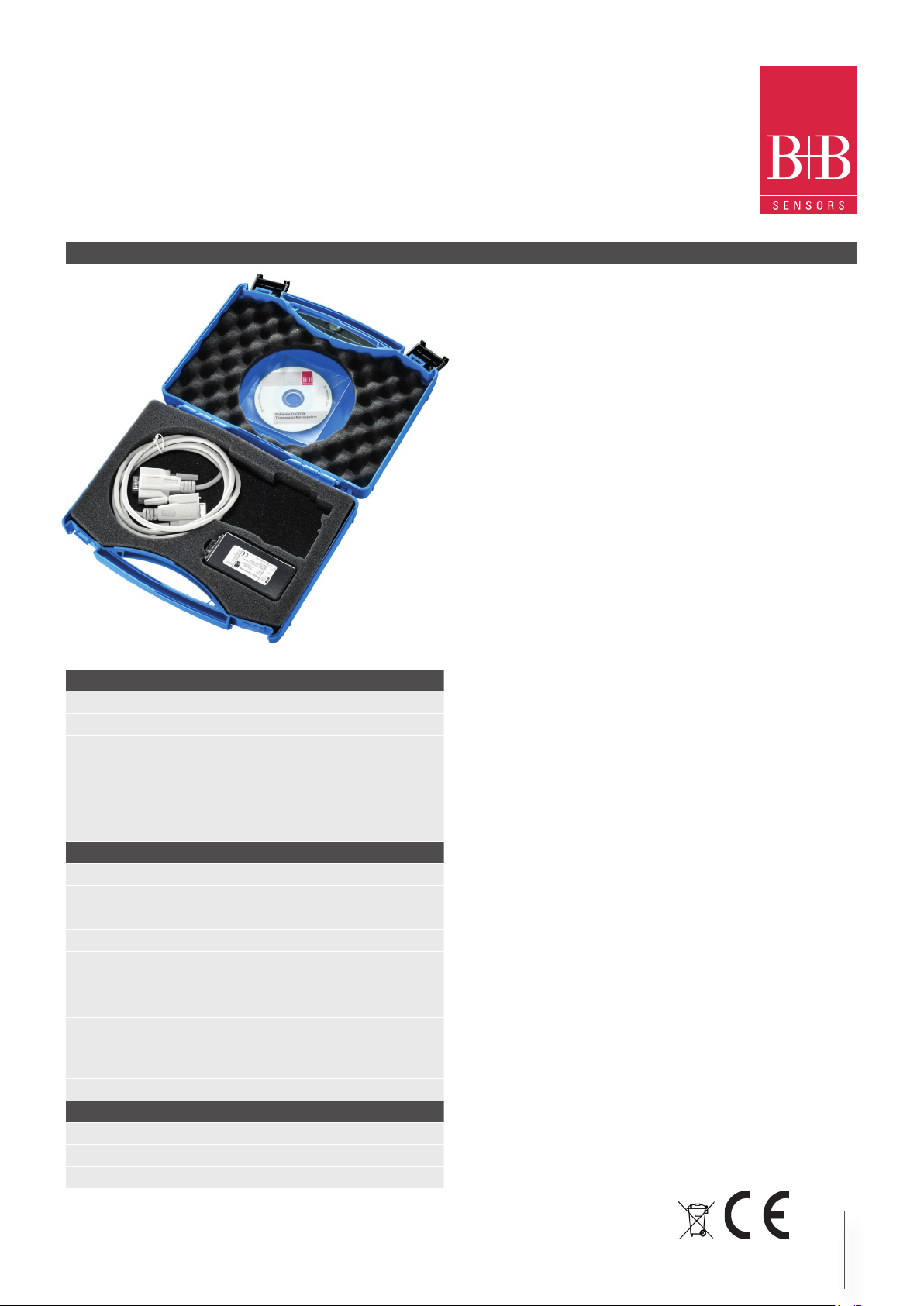
Temperature measurement system TLOG20
connections RS232, RS485, USB
DescriptionDescription
Characteristic features
• Up to 20 temperature measurement points
measuring range –55…+125 °C
• Use of temperature probe DALLAS-Sensors type 18B20, 18S20
• Three wire, parallel connection of sensors
• More than 60 meter lead length
• 0.06 °C resolution
• Automatic conguration
• Inclusive simple Windows™ software
Areas of application
• Monitoring of cold storage or stock rooms,
in food industry
• Quality assurance
• Temperature measurement in buildings,
0567 0002 (RS232-Interface)
The variants with other interfaces look slightly different
air conditioning, heating control, solar plants
• Dallas connection adapter for customer specic software on Windows or Linux platform
Technical Data
Temperature measurement
Number of channels congurable, 1 to 20
Measurement range -55...125 °C
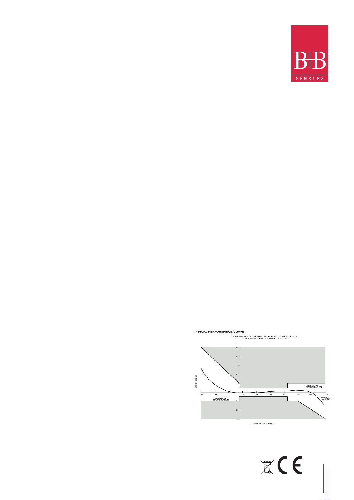
Typical accuracy
for sensor DS18B20:
for sensor DS18S20:
Module
Dimensions modul
Operating temperature
Micro controller circuit
Operating voltage DC
Operating current approx. 40 mA
Interface
CE-Conformance
EMV-noise emission:
EMV-noise withstanding:
Accessories See ordering numbers on page 5
Article number Interface
0567 0002
0567 0003 RS485
0567 0004 USB 1.1, 2.0 and 3.0 compatible
conform wirh the used sensor
±0,5 °C (-10...+55 °C)
±2 °C (-55...-10 °C, +85...+125 °C)
±0,5 °C (0...+70 °C)
(see curve on page 2)
L785 x W40 x D21 mm
-10...+55 °C
9 V-15 V DC (mains plug)
4800 Baud, 8 Data bits,
No parity, One Stop bit
2004/108/EG
EN 61000-6-3:2011
EN 61000-6-2:2007
RS232
Windows Software
• Display of current temperature values
• Tabular representation of measured values
• Storing of data on hard disk
• Graphics Software as accessories
Operation
The product offers an efcient measurement and indication system for a
maximum of 20 temperature channels. DALLAS sensors of type 1820,
18B20 are used as temperature sensors and these are connected in parallel with a three wire lead. By using suitable cables, it is possible to achieve
larger lead lengths up to a few hundred meters.
The integrating member between PC and sensor network is a micro controller module which is inserted at the serial COM-Port and makes the DALLAS-Touch-Bus ready through a six pole RJ12 plug connector. Suitable
connection cable or measurement sensor can be easily made or can be
readily procured from us.
The micro controller controls the dallas touch bus, manages the serial numbers and picks up the temperatures of all connected sensors in a cyclic
manner. The currently measured values are sent as ASCII string to the connected PC. The display and graphical representation of measured values
(option) appears on the PC. An easy to use Windows software for display
of measured values and data representation is included in the scope of
supply.
More such modules can be operated with a PC, provided more free COMports are available at our disposal.If the program RECORDER is used, only
one module per PC can be read.
Technical changes reserved
0141 0316-155 18.08.2015
B+B Thermo-Technik GmbH | Heinrich-Hertz-Straße 4 | D-78166 Donaueschingen
Fon +49 771 83160 | Fax +49 771 831650 | info@bb-sensors.com | bb-sensors.com
1 / 5
Page 2
OPERATION MANUAL
Temperature measurement system TLOG20
connections RS232, RS485, USB
WINDOWS-Software RECORDER
With the help of this program the measured values can be received through the interfaces and recorded on the PC. The
recorded data is compatible with any desired spread sheet
program, with which it is possible to further process the measured values for statistical evaluation and interpretation.
Installation: The program should be rst installed under Windows 98,
Windows NT, Windows 2000, Windows XP, Windows Vista or Windows
7 system. Place the attached CD in your drive and run the program
“setup.exe” either by selecting “Run“ from the START menu or through
the windows explorer. Then follow the instructions of the installation
program. The setup program creates a new program group “HYGROSENS INSTRUMENTS” in the folder “programs”. After successful
installation, the software can be accessed and executed through the
START menu.
First time operation: Connect the temperature logger to a free serial
port on the PC. If the software runs for the rst time in the menu option “settings” , select device type as “20Ch. Thermometer Templog
4800Bd” and also the serial interface used ( for example, COM1) under
“interface”. The remaining settings (Data rate, Parity, Start and Stop
bit) are automatically selected and need not be changed. In case the
connection hangs, refer to data communication in the terminal window.
Then select “OK” the current settings will be stored.
Please note that still micro controller adapter has to be congured as
per the connected sensors, before displaying the measurement values.
Data communication: The maximum allowable distance (between PC
and interface converters) depends on the model of the interface adapter.
USB-Interface: For USB-Interface the max. allowable length is restricted: As per standard, only 5 m are allowed. Due to high frequently
signals, this value should not be exceeded with the use of passive
connection cables. Only special USB cables may be used. For further
routes, special repeater-cables are available, which extend the allowable radius by 15 m in each case. Max. 5 such repeaters can be
cascaded. (No extend of delivery)
RS232-version: As per standard, the allowable cable length is 15 m. In
actual practice much longer routes, for example up to several 100 m,
can also be realised with low baud rates.
RS485-version: For very large distances between PC and sensor connection adapter, the RS485-version can be used. With this the connection length up to 1200 m can be realised. On the PC side a RS485interface adapter is required.
Data recording: First activate all the measurement channels for recording by checking the channels. In ‘Text 1’, ‘Text 2’ and ‚Text 3‘, you can
enter a description as header of the data le. The selected separator
appears between the individual data elements. Enter the recording in-
terval in seconds in the Field “Every”. The data is recorded in the le
which is entered as path in the ‘Settings’ button. The recording begins
by pushing the ‘Start’ button.
EXCEL™: If you want to use EXCEL for evaluation, then operate the
control button EXCEL before start of recording, so that suitable decimal
separation characters and eld separators are inserted. The created
le is compatible with CSV-Format. In order to display the measured
data, you can use graphic tools, for example, the diagramassistant in
EXCEL™. However, other software can also be used to evaluate the
measured data.
Connection of Sensors
The Dallas temperature sensors of type 1820 has an internal coding
(serial-number) and can be operated along with several other sensors
on a three wire bus. The sensors are calibrated by the manufacturer.
For short connection lengths, there are no special requirements in respect of the connecting cable to be used. It is also recommended to
connect a ceramic capacitor of 100 nF from pin +5 V to pin GND at
each sensor.
The lead length with unshielded cables can go up to 60 m. To increase the
approach length, an additional Pullup-resistor of 1.5k to 10 k-Ω (from Pin
“DALLAS” to pin “+5 V”) can be added. With this, it is possible to increase the cable length up to 150 m or more, but with slightly lower accuracy
of measurement due to the increased temperature rise of the sensors.
If you are not able to make any data communication between PC and
the measuring device or the measuring adapter, then rst please check
the power supply and also cable connection to the PC.
Technical changes reserved
0141 0316-155 18.08.2015
B+B Thermo-Technik GmbH | Heinrich-Hertz-Straße 4 | D-78166 Donaueschingen
Fon +49 771 83160 | Fax +49 771 831650 | info@bb-sensors.com | bb-sensors.com
2 / 5
Page 3

OPERATION MANUAL
Temperature measurement system TLOG20
connections RS232, RS485, USB
Format of Data transfer
Plug connector layout
Power supply: The articles 0567 0022 and 0567 0003 get their power supply via socket-plug.The inner core of the 3.5 mm socket-plug
carries positive operating voltage of approximately 9 to 15 V DC. The
outer conductor is minus.
The power supply for article 0567 0004 is given via USB-port.
Sensor- plug connector: The Western plug connector 6P6 (RJ12) on
the logger side is as shown below (view of the cable i.e. the contact
surfaces of the plug):
1 GND
2 GND
3 Data
4 Data
5 +5V
6 +5V
The interface works at a data rate of 4800 Bd, 8 databits, no parity
and one stop bit. The transfer of useful data takes place in lines. All
characters are ASCII coded. All information is sent continuously without separation characters. In a line, only information of one channel
is transferred. At the end of the line, the last two ASCII characters are
sent for the check sum (8 bit CRC) of the current line. Each line closes
with the character ‘Carriage return’ ‘<CR>´. Several lines form a data-
block. A data-block can have the following contents, for example:
Automatic sensor search
The system should be congured once before rst time operation. For
this, rst all sensors are connected and operating voltage is applied.
• After pressing the ‘Conguration’ key on the board shortly for
three times (in each case, approximately pressing for 1,5 seconds and then pausing for one second), the program goes into
Autosearch mode. The LED consecutively blinks three times in a
cyclic manner for short duration.
• If now the ‚Conguration‘ key is operated for at least 5 seconds,
the sensors connected on the bus are searched and the new con-
guration is stored in the controller´s memory. The process can as
often be repeated as desired. After the sensors are searched and
identied, the current temperature values appear on the screen.
• To exit from the Auto search mode, the operating voltage must be
switched off for a short while. The conguration remains stored.
• During execution of Autosearch-Function, the stored calibration
values are also deleted (see below).
The data block has following structure:
• A synchronization pattern for the beginning of a Data block. For
synchronization, the sequence ´@ <CR>´ is used.
• The conguration data (´Identier´) of a channel. The data line
begins with the character ‘I’, followed by the logical channel num-
ber, and then followed by conguration data and the Sensor serial
number. The line is closed with the check sum and the character
<CR>.
• The measurements of a channel. The data line begins with the
character ´V´, followed by the logical channel number, followed by
useful data. Only numerical measurement values and the check
sum (CRC), at the end of the line, are transferred. All other information like number format, number of characters, physical unit,
etc. are contained in the conguration data (sensor coding).
• The conguration data and measurement values follow the same
scheme for all other channels.
• The continuation character ´$´ <CR>´ is sent at the end of a data-
block
Structure of Cong Dataline
The conguration data line contains all information of the sensor wor-
king on the corresponding channel. The line has following structure:
• Character ´I´ at the beginning of the line.
• 8 bits (two ASCII characters) physical sensor coding. Based on
sensor coding, the number format, scale, physical unit and allowable range
• of values are specied. The sensor coding is 01 for the described
device.
Technical changes reserved
0141 0316-155 18.08.2015
B+B Thermo-Technik GmbH | Heinrich-Hertz-Straße 4 | D-78166 Donaueschingen
Fon +49 771 83160 | Fax +49 771 831650 | info@bb-sensors.com | bb-sensors.com
3 / 5
Page 4

OPERATION MANUAL
Temperature measurement system TLOG20
connections RS232, RS485, USB
• 8 bits (two ASCII characters) Hardware coding (type of the measurement sensor). The Dallas sensors have the code number 10
for 1820 and 28 (HEX) for 18B20.
• 48 bits (twelve ASCII characters) serial number of the sensor:
Here, the serial number of Dallas-sensor is mentioned.
• 8 bits (two ASCII characters) CRC (check sum)
• ´ <CR>´ as line termination
Structure of Measured value Datalines
The measurement value data line contains the current measurements
of the sensor operating on the corresponding channel. All information
are represented in binary and is transferred ASCII coded format without separation characters. For the sensor marking 01, the line has
following structure:
• Character ´V´ at the beginning of the line
• 8 bits (two ASCII character) logical channel number
• 2 Bytes (4 ASCII characters) measurement data with 0.01°C resolution. The hexadecimal value is to be converted into a decimal
number and to be divided by 100. With this, the temperature
value is obtained in °C with two decimals.
• 8 bits (two ASCII characters) check sum (CRC)
• ´<CR>´ as line termination
& Click, the window section can be enlarged and the time or temperature axis can be scaled as desired. Besides the graphic view, the
representation is also possible in the form of a table. Cut & paste is
used for capturing measured data series into a spreadsheet program
(for example EXCELTM). All tables and graphic representations can
be printed out in colors. In addition, simple monitoring and controlling
functions are also integrated in the software. Limits can be set for each
channel. An acoustic signal (Wave le) is given when the values are
exceeded. Control of up to eight external devices is possible by a relay
card, to be attached at the parallel port or USB connector.
Software Prolab
Accessories (Optional)
Software “PCLOG“
The software screen are in English and German language. Temperature values can displayed in °F or °C. Besides data storing on hard
disk, the software offers as most important feature the graphical representation of all measured and recorded channels in the form of a
temperature Vs time chart (online scriber function). By means of Drag
With this software, professional measurement and control projects can
be realized in a simple, graphics based development platform. You can
simply draw the wiring diagram of the measurement circuit and do the
project design. Without any knowledge of programming, the measurement values of up to 16 temperature sensors can be easily used in the
measurement circuit.
Arithmetic and logical components take care of linking and processing of the measurements. Modules like impulse generators, timers
and relay cards etc. provide extensive possibilities for control and regulation. Various instruments, scribers and tables serve as the storage and representation of measured values and you can monitor the
measurement system with display and control elements. The system
is operated through a self designed front panel, on which you can ar-
range switches, potentiometers, displays, LED´s, instruments etc. The
software also enables compilation of the project into an EXE-le, which
can run without Prolab.
Technical changes reserved
0141 0316-155 18.08.2015
B+B Thermo-Technik GmbH | Heinrich-Hertz-Straße 4 | D-78166 Donaueschingen
Fon +49 771 83160 | Fax +49 771 831650 | info@bb-sensors.com | bb-sensors.com
4 / 5
Page 5

OPERATION MANUAL
Temperature measurement system TLOG20
connections RS232, RS485, USB
Ordering numbers
Attention
Artciel Article no.
PC-measurement with RS232 interface 0567 0002
PC-measurement with RS485 interface 0567 0003
PC-measurement with USB interface 0567 0004
Accessories Ordering No.
Switching AC/DC adaptor, 12 V, 670 mA
(not needed for 0567 0004)
Screw type temperature probe M10,
cable 2 m
Temperature probe DS1820 with PUR cable
and RJ12 plug, 2 m
Temperature probe DS1820 with PUR cable
and RJ12 plug, 5 m
Distribution box 10- port with housing VERT-GEH
Software Prolab expert PROFILAB
For further information, please visit our homepage:
www.bb-sensors.com
NG-12V-670MA
DS1820-HD-2MM10
DS1820-PUR-2M
DS1820-PUR-5M
Please avoid extreme mechanical and inappropriate exposure.
The device/product is not suitable for potential explosive areas and
medical-technical applications.
Technical changes reserved
0141 0316-155 18.08.2015
B+B Thermo-Technik GmbH | Heinrich-Hertz-Straße 4 | D-78166 Donaueschingen
Fon +49 771 83160 | Fax +49 771 831650 | info@bb-sensors.com | bb-sensors.com
5 / 5
 Loading...