

INSTRUCTION MANUAL
Technical changes reserved
B+B 0141 0315-21 June 2011
B+B Thermo-Technik GmbH | Heinrich-Hertz-Straße 4 | D-78166 Donaueschingen
Fon +49 771 83160 | Fax +49 771 831650 | info@bb-sensors.com | bb-sensors.com
01 / 25
Description
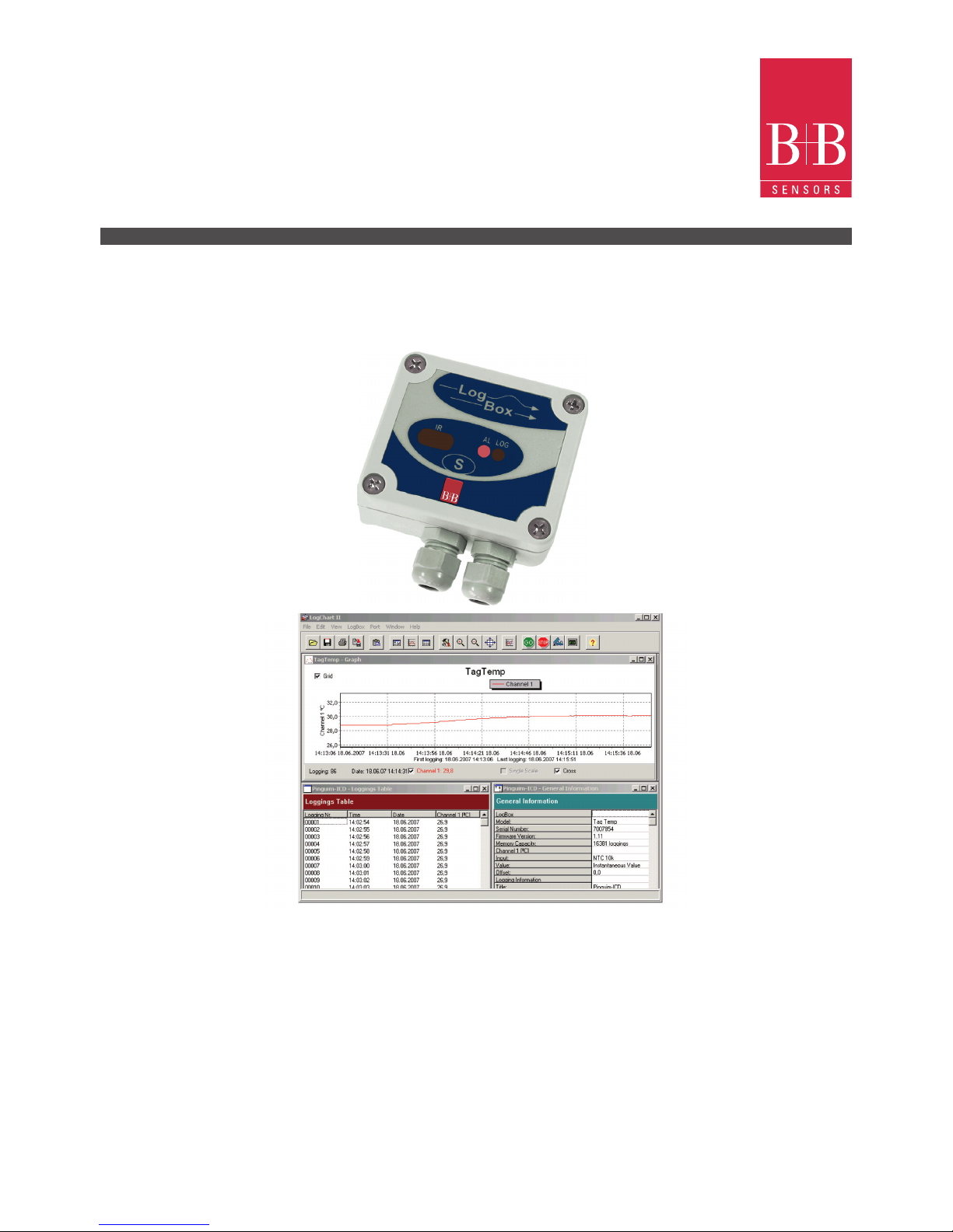
Data Logger LogBox AA IP65/67

INSTRUCTION MANUAL
Technical changes reserved
B+B 0141 0315-21 June 2011
B+B Thermo-Technik GmbH | Heinrich-Hertz-Straße 4 | D-78166 Donaueschingen
Fon +49 771 83160 | Fax +49 771 831650 | info@bb-sensors.com | bb-sensors.com
02 / 25
Dear customer,
We thank you for having purchased the LogBox IP65/67 and we are very glad that you decided to buy a product of
B+B Thermo-Technik GmbH. We hope this product will fully satisfy you and will assist you effectively in your work.
This Device has been developed to be technically highly up-to-date and has been designed in accordance with the
regnant European and German national directives and rules. For a proper and effective usage of the product the customer
shall observe the following Operating Instructions. In the case that against one’s expectations any trouble occurs which
you can not resolve yourself, please contact our service centers or our authorized dealer. We will provide you rapid and
competent help to minimize the risk of long time outfalls.
The following operating Instruction is an indispensable part of this Product. It contains important advices for the starting up
and further use of the device.
Foreword
This Operation Manual is intended to serve as an aid in the proper setup, installation and operating of the B+B product.
All essential details of the equipment and all actions required on the part are clearly presented and explained. We thus ask
that you read this manual carefully before proceeding to work with the equipment. Keep this manual available for ready
reference in a convenient and conspicuous location near the equipment.
General Information

INSTRUCTION MANUAL
Technical changes reserved
B+B 0141 0315-21 June 2011
B+B Thermo-Technik GmbH | Heinrich-Hertz-Straße 4 | D-78166 Donaueschingen
Fon +49 771 83160 | Fax +49 771 831650 | info@bb-sensors.com | bb-sensors.com
03 / 25
Content
Foreword 02
General Information
Symbols Employed 04
Warning Signs
Safety Instructions 05
Intendend Use 06
Disposal
1. Product Description 07
2. Scope of Delivery
3. Optional or accessory
4. Identication 08
5. Properties
6. Memory Capacity
7. Input Signals
8. Operation 09
8.1. Drivers and software installation
8.2. Start LogChart-II Software 10
8.3. Conguration the logger 11
8.4. General Information 12
8.5. Acquisition
8.6. Start Logging Field 13
8.7. Stop Loggings
8.8. Channels Field
8.9. Electrical connections 14
9. IP65 Model 15
9.1. IP67 Model
9.2. Input Connections 16
9.3. External Battery Switch
9.4. Digital Input
9.5. Installation Recommendations 17
9.6. Ofoading and Data Visualisation
9.7. Graph Window
9.8. Acquisitions Table Window 18
9.9. General Information table
10. Visualizing the data 19
10.1. Monitoring Acquisition
10.2. Conguring the logger - Settings
10.3. Downloading Data from the Logger 22
10.4. File Visualization
10.5. Transfering Data to your Desktop
11. Observations 23
INSTRUCTION MANUAL
Technical changes reserved
B+B 0141 0315-21 June 2011
B+B Thermo-Technik GmbH | Heinrich-Hertz-Straße 4 | D-78166 Donaueschingen
Fon +49 771 83160 | Fax +49 771 831650 | info@bb-sensors.com | bb-sensors.com
04 / 25
Symbols Employed
Sign Meaning
Notice
Advice
It is necessary to read the following advices before using the product.
The used symbols in the manual acts rst of all as eye catcher for security risks. The symbols do not replace the security advices. The text must
be read completely.
Necessarily to observe
This symbol designates important advices and tips which are necessary
for the success of a procedure. They have to be followed in order to get
good results.
Warning Signs Meaning
This symbol advises the user of danger for persons, material or environment. The text gives information
that must be necessarily followed to avoid any risks
Caution against hot surfaces (BGV A8, GUV-V A8/W26) and hot liquids or substances
Caution against liquids and hot substances
Caution against dangerous explosive substances (BGV A8, GUV-V A8/W02)
Caution against moving maschines (W29)
Caution against moving parts
Caution against electromagnetic elds (BGV A8, GUV-V A8/W12)
Caution against severe cold (BGV A8, GUV-V A8/W17)
Caution against dangerous high electrical voltage (BGV A8, GUV-V A8/W08)
Caution against dangerous explosive atmosphere (BGV A8, GUV-V A8/W21)
Electronic waste
Warning Signs
13. Most frequent problems
14. Maintenance
Dimensions
Technical Data 24
Questions 25

INSTRUCTION MANUAL
Technical changes reserved
B+B 0141 0315-21 June 2011
B+B Thermo-Technik GmbH | Heinrich-Hertz-Straße 4 | D-78166 Donaueschingen
Fon +49 771 83160 | Fax +49 771 831650 | info@bb-sensors.com | bb-sensors.com
05 / 25
Safety Instructions
For damages caused by failure to observe these safety and operating instructions, takes over the B+B Thermo-Technik GmbH
is not liable.
This device has been designed and tested in accordance to the safety regulations for electronic devices.
However, its trouble-free operation and reliability cannot be guaranteed unless the standard safety measures and special safety
advises given in this manual will be adhered to when using it.
Trouble-free operation and reliability of the device can only be guaranteed if it is not subjected to any other climatic conditions
than those started under “Specication”.
If the device is transported from a cold to a warm environment condensation may result in a failure of the function. In such a
case make sure the device temperature has adjusted to the ambient temperature before trying a new start-up.
If device is to be connected to other devices the circuitry has to be designed most carefully. Internal connection in third party
devices (e.g. connection GND and earth) may result in not-permissible voltages impairing or destroying the device or another
device connected.
Warning:
Just devices with mains input: If device is operated with a defective mains power supply (e.g. short circuit from mains voltage to
output voltage) this may result in hazardous voltages at the device (e.g. at sensor socket)
If there is a risk whatsover involved in running it, the device has to be switched off immediately and to be marked accordingly to
avoid re-starting. Operator safety may be a risk if:
● There is visible damage to the device
● The device is not working as specied
● The device has been stored under unsuitable conditions for a longer time
In case of doubt, please return device to manufacturer for repair or maintenance.
Caution:
Do not use these product as safety or emergency stop devices, or in any other application where failure of the product could
result in personal injury or material damage. Failure to comply with these instructions could result in death or serious injury and
material damage.
INSTRUCTION MANUAL
Technical changes reserved
B+B 0141 0315-21 June 2011
B+B Thermo-Technik GmbH | Heinrich-Hertz-Straße 4 | D-78166 Donaueschingen
Fon +49 771 83160 | Fax +49 771 831650 | info@bb-sensors.com | bb-sensors.com
06 / 25
Intendend Use
Disposal
The use of the unit in elds other than those indicated under “SAFETY INSTRUCTIONS” is not allowed for safety reasons.
This instruction manual does not at all substitute any additional instruction manual of connected accessoriy!
This unit has been marked in accordance with the European Device 2002/96/EC on waste electrical and electronic
equipment (WEEE).
At the end of its useful operating life, dispose of the unit as electrical scrap.
Please ask either B+B Thermo-Technik GmbH or your specialist dealer for information on your local collection point.
Within the scope of application if this Directive, B+B Thermo-Technik GmbH is responsible for proper disposal of this unit.
INSTRUCTION MANUAL
Technical changes reserved
B+B 0141 0315-21 June 2011
B+B Thermo-Technik GmbH | Heinrich-Hertz-Straße 4 | D-78166 Donaueschingen
Fon +49 771 83160 | Fax +49 771 831650 | info@bb-sensors.com | bb-sensors.com
07 / 25
1. Product Description
The LogBox-AA is an electronic data logger with two analog input channels, which accept a variety of standard sensors and
0 (4) to 20 mA, 0 to 50 mV or 0 to 10V signals. It also provides a signal for commanding an external power supply (battery)
of a device connected to the logger. This feature allows that the power supply of external devices, such as a transmitter, occurs
only during the measurement sample time, thus extending the service life of these external batteries. It can be supplied either in
the IPtwo.
The measured values are stored in the logger electronic memory (acquisitions) for later download to a PC for visualization and
analysis in the form of tables or graphs. Data can be easily exported to spreadsheets.
The conguration of the logger can be effected only with use of the IrLink 3 infrared communication interface.
The LogChart-II is the software used to congure the logger, download and visualize data. The logger conguration allows
dening the logger operation mode, including the start/stop time of data acquisition. Other parameters such as signal input type,
logging interval, etc., is easily selected through the LogChart-II software.
2. Scope of Delivery
Article Name Article Number
Description
Datenlogger AA IP 65
0568 0033 1 x Data Logger LogBox AA IP65,
1x CD-ROM with Logchart-II Software and a USB Treiber,
2x wires for Sensor Wiring, 1x Quick Logger Operating Instructions, 1x Ordering Informations
Datenlogger AA IP 67
0568 0034 1 x Data Logger LogBox AA IP67,
1x CD-ROM with Logchart-II Software and a USB Treiber,
2x wires for Sensor Wiring, 1x Quick Logger Operating Instructions, 1x Ordering Informations
3. Optional or accessory
Article Name Article Number
Description
Communication interface
0568 0036 IR-Interface with USB-Connection
Datenlogger LogBox-AA
INSTRUCTION MANUAL
Technical changes reserved
B+B 0141 0315-21 June 2011
B+B Thermo-Technik GmbH | Heinrich-Hertz-Straße 4 | D-78166 Donaueschingen
Fon +49 771 83160 | Fax +49 771 831650 | info@bb-sensors.com | bb-sensors.com
08 / 25
6. Memory Capacity
Two memory storage capacities are offered:
32k Model: Allows up to 32,000 records
64k Model: Allows up to 64,000 records
Memory capacity is always shared between enabled channels. In case there are two channels enabled, each gets 50 %
of the memory available. When only a single channel is enabled, it has the entire memory at its disposal.
Memory capacity is indicated on the identication label placed on the logger rear panel.
7. Input Signals
The input channels 1 and 2 measure analog electric signals, which can be Pt100, Thermocouple (J, K, T, E, N, R, S or B),
voltage (0 to 50 mV or 0 to 10 V) or current (0 to 20 mA or 4 to 20 mA), according to user-dened settings.
Note: Besides conguration performed through the software, the denition of input signal requires two internal jumpers to
be congured.
Data Acquisition (logging)
Data can be acquired through different modes. The logger can be congured to perform a single measurement within a time
interval storing the value read or perform ten measurements within the time interval and store the mean of values measured.
Yet, it can store the minimum or maximum values read in the interval.
5. Properties
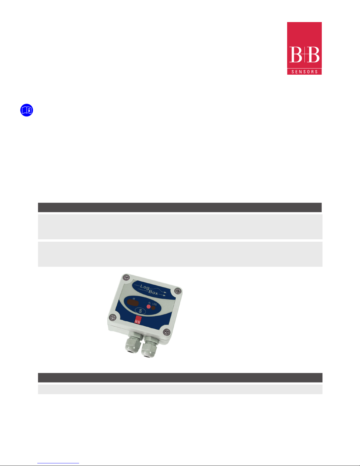
Parameter
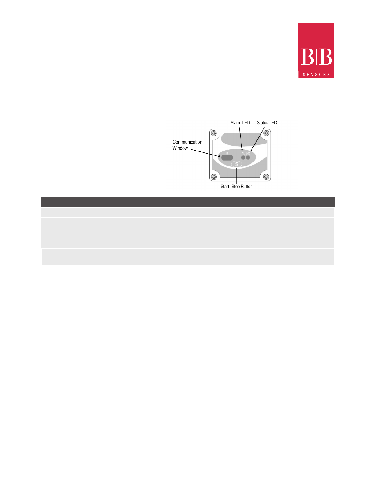
Start-/stop button (S) This button can be congured to start or stop the temperature measurement process.
IR communication window PC-Logger communication area. During download, the communication interface must be
constantly directed towards this window
Status indicator (LOG) While in stand-by (not logging) or after a series of measurements, it ashes once at every
four seconds. During logging it ashes twice at every four seconds
Alarm indicator (AL) Warns the user as to alarm conditions. Whenever an alarm situation takes place it will ash
once at every four seconds, until a new conguration is applied to the logger
4. Identication
The identication label is on the logger body. Check if the features described are in accordance with your order.
The following elements are shown in the logger front:
INSTRUCTION MANUAL
Technical changes reserved
B+B 0141 0315-21 June 2011
B+B Thermo-Technik GmbH | Heinrich-Hertz-Straße 4 | D-78166 Donaueschingen
Fon +49 771 83160 | Fax +49 771 831650 | info@bb-sensors.com | bb-sensors.com
09 / 25
8. Operation
The logger operation mode is user-defined in the Log-
Chart-II software. To access or change this conguration,
the Communication interface is required. The user must
install the LogChart-II software in a computer and run the
logger conguration according to instructions dened in
the LogChart-II installation section of this manual.
After conguration and input electric connections made,
the device is ready to measure and log input signals. The
status indicators show the logger current status.
Essential Accessories:
• A PC-System with Windows® 2000 oder Windows XP®
• CD-ROM device
• A free USB-Port
The status lights of the logger startes ashing according to
the current status of the logger:
• A ash every four seconds (stand-by) means the logger is ready for a new measurement or the logger has
completed a series of measurements and is waiting
for a new command.
• Flashes twice every four seconds, a current measurement is active.
The settings of the data logger operation will be done in the LogChart-II software. Each setting must be dened and its
action can be controlled. The data logger starts and stops his notes as they are predened in the settings.
8.1. Driver and Software Installation
In the Communication Interface model is a USB/Ir communication interface, which must be connected to the available
USB-port. Windows® will request a proper driver installation, which is found in the CD-ROM that is provided with the logger.
The driver installation steps may vary according to the machine, even for the same version of an operating system.
The following screenshots and steps are only to provide guidance.
1. Insert the CD shipped with the logger in the CD-ROM
drive.
2. Connect the communication interface IrLink-3 to the PC
USB-port. Windows® will acknowledge the presence of
new hardware and a few seconds later it will start the
driver installation process.
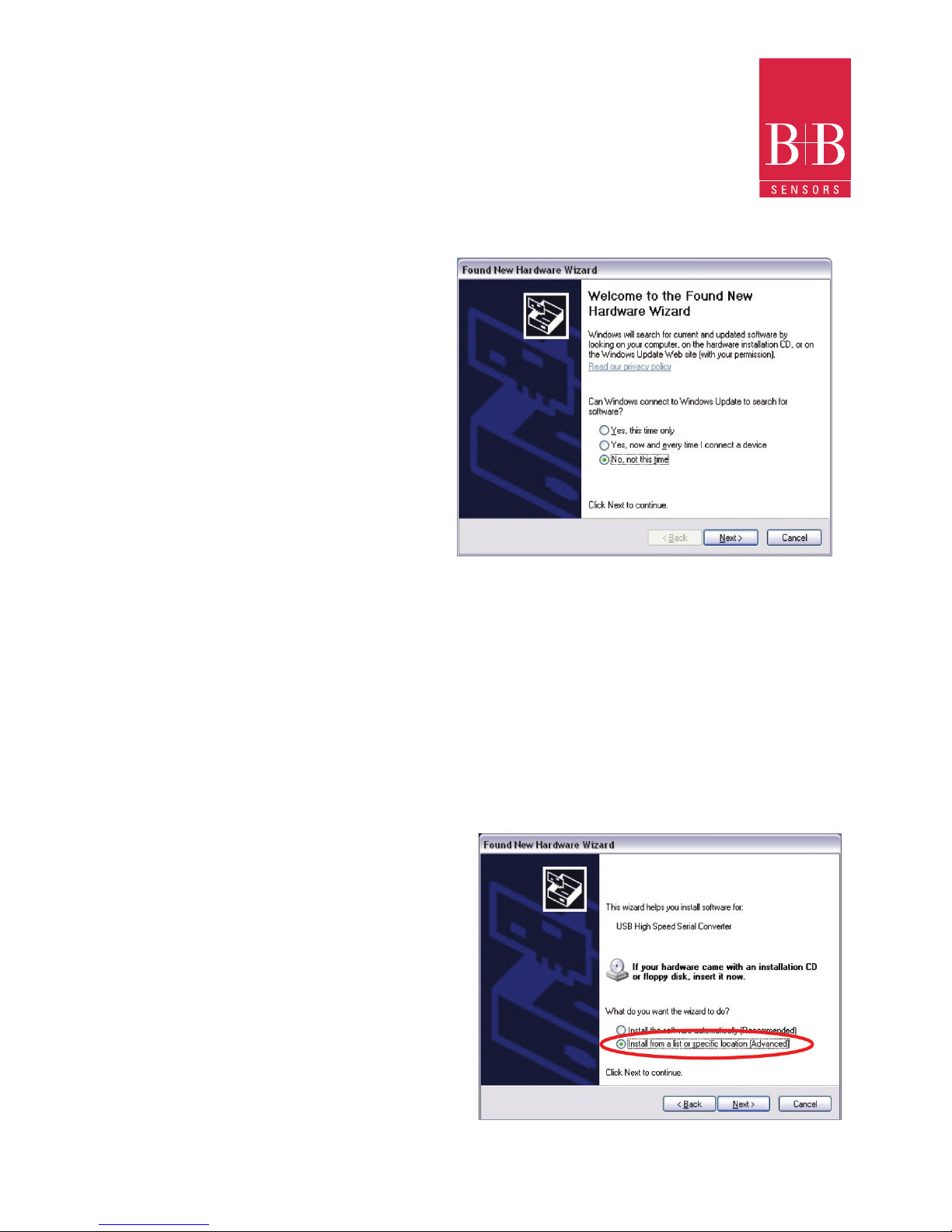
3. The window “found new hardware wizard” will be displayed, and you will be asked if you want to install the
driver from the Windows Update website. Select “No, not
this time”, and then click Next.
4. Select “Install from a list or specic location (Advanced)”
and click “Next”.
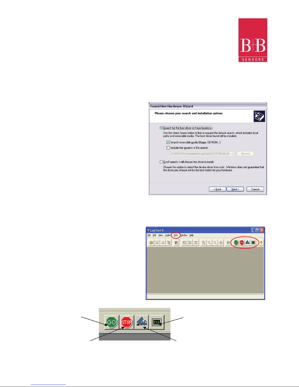
5. Select “Search for the best driver in these locations” and
check “Search removable media”. Click “Next”.If installation les are not in a CD, check “Include this location in the
search” and show the le path.
INSTRUCTION MANUAL
Technical changes reserved
B+B 0141 0315-21 June 2011
B+B Thermo-Technik GmbH | Heinrich-Hertz-Straße 4 | D-78166 Donaueschingen
Fon +49 771 83160 | Fax +49 771 831650 | info@bb-sensors.com | bb-sensors.com
10 / 25
In later uses of the interface, Windows® may require
the driver installation again. In this case, the same
installation wizard will be displayed, and you will have
to select the option “Install software automatically
(recommended), as the driver may already be in the
computer.
Logchart-II Software installation:
1. Insert the supplied CD-ROM in the CD-drive of
the PC.
2. The software installation wizard will start automatically. If it does not, please run the
„LC_II_Setup.exe“ program provided from your
CD-drive.
To do so, please follow the steps below:
• From the start menu of Windows run Windows
Explorer. Choose the CD drive
• Double click on the icon „LC_II_Setup.exe“ to run
the setup-program.
• Follow the steps described in the setup-wizard
8.2. Running LogChart-II
By starting the program, the main window will appear on
the screen:
The LogChart-II requires a communication port to talk to
the logger. Clicking on the menu Port, all free communication
ports available in the computer will be listed, including the
USB port if the driver is installed. Select one and connect the
corresponding wand to it. The chosen port will be remembered next times the LogChart-II is initiated.
Displays the Cong-
uration Setup dialog box
Press this button
to represent the last 10
measurements taken
Press this button to
the current contents of the logger
download store
Stops current
Measurements
6. If a prompt warns you that it does not support Windows® XP or that signature verication failed, click “Continue anyway”.
7. The interface driver les will be copied to the computer and after a few seconds a screen is displayed informing you that the
software installation has been concluded. Click “Finish”.
8. In some situations, the steps described above may be repeated again. Follow the same procedures.

INSTRUCTION MANUAL
Technical changes reserved
B+B 0141 0315-21 June 2011
B+B Thermo-Technik GmbH | Heinrich-Hertz-Straße 4 | D-78166 Donaueschingen
Fon +49 771 83160 | Fax +49 771 831650 | info@bb-sensors.com | bb-sensors.com
11 / 25
8.3. Conguration the logger
Make sure the communication interface is connected to the PC-port which is selected. The interface must be constantly
directed towards the communication window on front part of the logger at a maximum distance of 0,5 m.
After the serial port is selected, click the “GO” button:
The following Parameters conguration dialog box is then displayed:
In this dialog box the user can dene the logger operation mode and also obtains general information about the device.
The different elds and their meaning are listed in the following.

INSTRUCTION MANUAL
Technical changes reserved
B+B 0141 0315-21 June 2011
B+B Thermo-Technik GmbH | Heinrich-Hertz-Straße 4 | D-78166 Donaueschingen
Fon +49 771 83160 | Fax +49 771 831650 | info@bb-sensors.com | bb-sensors.com
12 / 25
8.4. General Information
General information on the top of the screen informs about the model, serial number, logger current date/time, PC date/time,
rmware version (logger model version), memory capacity and the used memory. This information is displayed in the upper
part of the LogChart-II conguration screen. The time is permanently updated in this screen, provided that the logger and the
PC are communicating.
8.5. Acquisition
Parameter Function
Period It determines the interval between readings in the hh:mm:ss format. New data is stored in the
logger memory after each time interval. In the Average, Minimum and Maximum reading modes,
the logger executes 10 readings within this interval
External Battery Switch time Denes the time at which the logger turns on the external power supply, before proceeding with
any reading. This time is limited to 10 seconds and must be less than half of the interval between
readings
Estimated time It informs about the estimated time for the accomplishment of programmed readings based on
the logging “Interval” and on the number of programmed readings
Daily Repetition Allows loggings to be repeated everyday, for example, recording data from 8 AM to 5 PM day after
day. The start and stop times are dened in the elds “Start time” and “Stop time”
8.6. Start Logging Field
Parameter Function
Immediately The logger starts logging as soon as the conguration is applied. Not valid when the option
„Daily Repetition“ is selected
Day/ Hour Logging starts at a predened date and time. The date dened is used for the Daily
Repetitions option as well
Through Start Button Starts and stops logging by holding the Start button pressed for three seconds
Digital Input Starts readings when the digital input is activated (closed) and stops readings when the digital
input is deactivated (open)

INSTRUCTION MANUAL
Technical changes reserved
B+B 0141 0315-21 June 2011
B+B Thermo-Technik GmbH | Heinrich-Hertz-Straße 4 | D-78166 Donaueschingen
Fon +49 771 83160 | Fax +49 771 831650 | info@bb-sensors.com | bb-sensors.com
13 / 25
8.8. Channels Field
By selecting the “Channels” option, the user is able to choose the individual settings for each input channel.
Parameter
Function
At Full Memory Loggings can be stored up to the full memory capacity is reached
Wrap around Logging never stops. The LogBox will keep on recording the readings and when the memory is full it
will overwrite the oldest record in a circular or wrap around manner
After a dened number of readings The logger will stop logging after the number of readings dened here is reached. Not valid
when the option ‘Daily Repetition’ is selected
Day / Hour The LogBox will stop logging at the user-dened date and time. Not valid when the option ‘Daily
Repetition’ is selected
8.7. Stop Loggings
INSTRUCTION MANUAL
Technical changes reserved
B+B 0141 0315-21 June 2011
B+B Thermo-Technik GmbH | Heinrich-Hertz-Straße 4 | D-78166 Donaueschingen
Fon +49 771 83160 | Fax +49 771 831650 | info@bb-sensors.com | bb-sensors.com
14 / 25
8.9. Electrical connections
Only the input connections and the External Battery Switch (when used) are needed. The logger is exclusively powered by its
internal battery.
In the IP65 models, the inputs and the signal for activating the external power supply are located inside the logger case, which
must be opened for accomplishing the connections.
In the IP67 models, proper connectors are provided for this purpose.
The case cover should be opened only if necessarily required. If this is the case, the cover must be properly tightened back in
its place such as to assure the stated IP Ingress protection index.
Parameter Function
TAG Denes a name (up to 8 characters) for identifying the variable to be measured in the channel
Inputs The signal applied to the logger input is dened here. The list shows all the input options available.
The selected option must be in accordance with the internal conguration of the jumpers J1 and J2.
For more information refer to section 7 electrical connections
Unit Denes the variable unit
Scale Denes the range, in engineering units, to represent the input variable measured. Adjustable from –32000 to
+32000 for 4-20 mA, 0-20 mA, 0-50 mV and 0-10 inputs, for the remaining input types the scale is xed.
Offset Allows ne offset corrections on the measured value
Value Denes readings recording modes:
Instantaneous The instant value read at the logging time
Average 10 equidistant readings at each reading interval are taken.
The average value of readings is built and the resulting value
recorded
Minimum 10 readings at each reading interval. The lowest value found
is recorded
Maximum 10 readings at each reading interval. The highest value
found is recorded
Alarm Denes a limit range of variables measured, that once exceeded, trigger the alarm. Once activated
the alarm LED indicator stays so, even after the alarm-triggering situation has ceased, till a new
conguration is applied to the logger.
Low Denes the minimum value under which the alarm
is triggered
High Denes the maximum value above which the alarm is
triggered
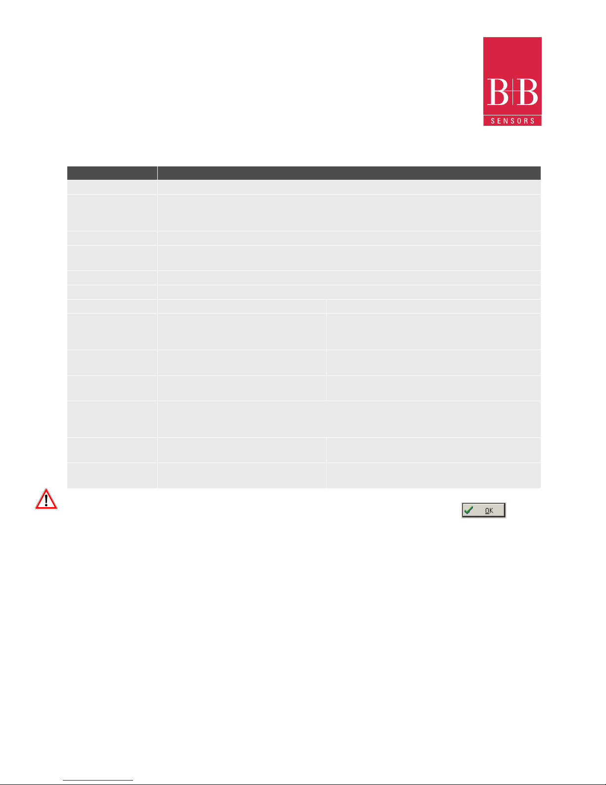
After lling all the elds for both channels, send the conguration to the logger by clicking on the button
The new settings and PC current date/time are then sent to the logger. All Data in the logger memory will be lost.
The parameters are:

INSTRUCTION MANUAL
Technical changes reserved
B+B 0141 0315-21 June 2011
B+B Thermo-Technik GmbH | Heinrich-Hertz-Straße 4 | D-78166 Donaueschingen
Fon +49 771 83160 | Fax +49 771 831650 | info@bb-sensors.com | bb-sensors.com
15 / 25
9. IP65 Model
Open the logger’s cover to get access to the block terminals and the conguration jumpers. Connection-cables must
pass through the compress tting located at the bottom of the case. The following gure shows the internal terminals
distribution.
Channel Connections
Channel 1 CN1 connector – Terminals 1, 2 and 3
Channel 2 CN1 connector – Terminals 4, 5 and 6
External Battery Switch CN2 connector – Terminals 7, 8 and 9
Digital Input CN2 connector – Terminals 7, 10 and 9
Note: Make sure that the compress tting is perfectly tightening the cables, thus
assuring proper Ingress protection IP65.
IP65: Totally dust-tight and protected against water jets.
Channel 1 cable (right) Connection
Brown CN1-3
Blue CN1-2
Black CN1-1
Channel 2 cable (left) Connection
Brown CN1-6
Blue CN1-5
Black CN1-4
9.1. IP67 Model
In the IP67 version, an M8 connector is provided for signal input.
Two connectors provide external access to the input channels as
shown in the gure. The cables are supplied with the logger.
Note: The case cover should not be opened unless it is really necessary. If this is the case, the cover must be properly tightened
back in its place such as to assure the Ingress protection IP67.
IP67 - Totally dust-tight and protected from temporary immersion
in water.
Wire connections:

INSTRUCTION MANUAL
Technical changes reserved
B+B 0141 0315-21 June 2011
B+B Thermo-Technik GmbH | Heinrich-Hertz-Straße 4 | D-78166 Donaueschingen
Fon +49 771 83160 | Fax +49 771 831650 | info@bb-sensors.com | bb-sensors.com
16 / 25
9.2. Input Connections
Both models have the same input connections schema:
In the IP67 version, an M8 connector is provided for signal input. Two connectors provide external access to the input
channels as shown in the gure. The cables are supplied with the logger.
Note: The case cover should not be opened unless it is really necessary. If this is the case, the cover must be properly
tightened back in its place such as to assure Ingress protection IP67.
IP67 - Totally dust-tight and protected from temporary immersion in water.
9.3. External Battery Switch
The example below shows the usage of the external battery switch for commanding the power supply of external devices.
Channel 1 is congured to 4-20 mA input signal. A battery is used to provide power to the 4-20 mA loop. The battery switch
“turns on” the power to the loop a moment (dened in the conguration) before the measurement is taken, enabling the transmitter (pressure, temperature, etc.) to start up and stabilize the output.
9.4. Digital Input (DE)
The Digital Input can be used to externally trigger the start and stop of readings. It is available in terminals
7 (-) and 10 (+) of CN2.
Input signal Channel 1, J1 position
Channel 2, J2 position
4-20 mA / 0-20 mA A A
Pt100 / Thermocouple / 0-50 mV B B
0-10 V C C

INSTRUCTION MANUAL
Technical changes reserved
B+B 0141 0315-21 June 2011
B+B Thermo-Technik GmbH | Heinrich-Hertz-Straße 4 | D-78166 Donaueschingen
Fon +49 771 83160 | Fax +49 771 831650 | info@bb-sensors.com | bb-sensors.com
17 / 25
9.5. Installation Recommendations
Signal wires should be installed in grounded conduits and away from power or contactor wires. Instruments must be
powered only by an exclusive power supply.
System failure should always be taken into account when designing a control panel to avoid irreversible damage
to equipment or people. Installing RC lters (47R and 100nF, serial) is strongly recommended at contactor coils or
any other inductors.
9.6. Ofoading and Data Visualisation
The transfer of data to a PC is accomplished by using the LogChart II software. Data can be collected anytime and saved in les
for future analysis (menu “File Save” or “File Save as”). Help can be accessed from the LogChart-II software when necessary.
Ofoading data: Data ofoad is accomplished by clicking on the button „Ofoading“
or using the LogChart-II menu. During data transfer, a status bar indicates remaining data to be transferred. Data ofoading time
is proportional to the number of readings logged. At the end of data transfer, the Graph window is displayed with the downloaded
data plotted.
10.6. Graph Window
The Graph-window is a convenient tool for analysis.
It enables the logger acquisitions to be read in the form of
a “values vs. time” graph. As one moves the mouse in the
chart area, the time and the value of the records of each
channel are shown in the eld located in the bottom of
the window.
Zooming in and out are implemented. It is possible to
select an area by clicking and dragging the mouse, thus
creating a zoom region, starting at the upper left position
of the region of interest.
The command „Ofoad acquisitions“ does not interrupt
the process of data logging and reading.
Other two windows can be easily opened:
• Acquisitions Table Window
• General information table

INSTRUCTION MANUAL
Technical changes reserved
B+B 0141 0315-21 June 2011
B+B Thermo-Technik GmbH | Heinrich-Hertz-Straße 4 | D-78166 Donaueschingen
Fon +49 771 83160 | Fax +49 771 831650 | info@bb-sensors.com | bb-sensors.com
18 / 25
9.8. Acquisitions Table Window
Data acquired by one or both input channels
(user-dened) are displayed in engineering units in
a table format. The table displays register number,
date/time and the record values.
9.9. General information table
Displays information about the logger:
• Features
• Congurations
• Details about data acquired

INSTRUCTION MANUAL
Technical changes reserved
B+B 0141 0315-21 June 2011
B+B Thermo-Technik GmbH | Heinrich-Hertz-Straße 4 | D-78166 Donaueschingen
Fon +49 771 83160 | Fax +49 771 831650 | info@bb-sensors.com | bb-sensors.com
19 / 25
10. Visualizing the data
Three windows support data visualization: Graph, Acquisitions Table and General Information windows.
Data can be originated from direct reading from the logger or from a le previously recorded in a computer.
Once the windows are open, data can be saved in a le (.lch), printed on a graph or exported to a
text le (.txt or .dat).
10.1. Monitoring Acquisitions
To online visualize current measurement in a graph format, use the monitor On-line command
by clicking the button while pointing the IR-LINK3 interface to the logger.

INSTRUCTION MANUAL
Technical changes reserved
B+B 0141 0315-21 June 2011
B+B Thermo-Technik GmbH | Heinrich-Hertz-Straße 4 | D-78166 Donaueschingen
Fon +49 771 83160 | Fax +49 771 831650 | info@bb-sensors.com | bb-sensors.com
20 / 25
The parameters are analogous to the LogChart-II parameters.
The screen exhibits instant values of variables measured, conguration information and current logger status. The Buttons are
assigned the following functions:
Parameter Function
Search It allows you to search for another logger or reconnect communication lost for any reason. When the
handheld device nds a logger, it exhibits a new Monitoring screen with the logger information. When
other loggers are found, the Devices Found screen is exhibited again
Download Downloads logged data. Download can be partial and it does not interfere in the ongoing acquisition
process
More Infos Displays further information on the connected logger, such as model, serial number, version and
memory capacity
Settings Accesses the Settings screen, which allows modifying the logger conguration
Data base Exhibits the Recorded Data screen listing all the processes stored and processed in the PDA data base.
To access the data, tap on Details. Information required is displayed
View data Displays data in a list containing date, time and measured value
10.2. Conguring the logger - Settings
During conguration, the logger must be aligned. Click on „Settings“ in the Monitoring screen. The screen Settings is opened and
contains the required parameters for conguring the logger.

INSTRUCTION MANUAL
Technical changes reserved
B+B 0141 0315-21 June 2011
B+B Thermo-Technik GmbH | Heinrich-Hertz-Straße 4 | D-78166 Donaueschingen
Fon +49 771 83160 | Fax +49 771 831650 | info@bb-sensors.com | bb-sensors.com
21 / 25
Parameter
Function
Title Name of the process
Input 1 und 2 Informs about the inputs used by channel 1 and 2 respectively
Start Denes the strategy for the logging start. Options are:
Immediately The logger starts logging as soon as conguration is sent to the logger
By „data/time“ Start in dened data and time, always after current time. It is possible to perform daily repetitions.
If this option is selected, a new box to dene the stop logging time is displayed
Start Press the „Start-Now“ button from the Monitoring screen to start logging
LogBox Press the „Start-Now“ button from the Monitoring screen, the Palmtop should be pointed towards the
logger
Digital Input Readings are performed while the digital input is enabled (closed / 1) and interrupted when the digital
input is disabled (open / 0)
Stop Denes logging stop mode, options are:
Full memory Loggings can be stored up to the logger full memory capacity is reached
Wrap around Logging never stops. The LogBox will keep on recording the readings and when the
memory is full it will overwrite the oldest record in a circular or wrap around manner
After loggings The logging will stop after the number of readings here dened
By data/ time Logging is stopped on user-dened day and time
Interval Denes the interval between readings: hour, minute and second. For mean, maximum
and minimum values, the shortest interval between loggings is 10 seconds.
Channel 1 Opens the Input 1 Settings screen
Tag Denes a name for Channel 1
Input Informs the input type used in Channel 1
Unit Denes the unit of the variable. For 0-20 mA, 4-20 mA, 0-50 mV and 0-10V the user should write the required unit
Logging mode
It denes how the value measured will be logged. Options are:
Instantaneous 1 reading and 1 logging at each reading Interval.
Average 10 readings at each reading interval. The average value of readings is the value recorded.
Minimum 10 readings at each reading interval. The lowest value found is recorded
Maximum 10 readings at each reading interval. The highest value found is recorded
Lower/Upper
range value
Allows the user to dene the reading range for the 0-20 mA, 4-20 mA, 0-50 mV and 0-10V inputs.
Offset This parameter is used to correct small known mistakes the input signal may
present, such as during sensor switching, transmitter replacement, etc.
Alarms Enables an alarm that is triggered according to user-dened
parameters
Cancel and OK Buttons cancel and save congurations dened in Channel 2 screen
Channel 2 Has the same parameters as described for Channel 1
Clocks Provides access to Logger clocks. When a new
conguration is sent to the logger, clocks are updated
Battery Denes the moment when the logger turns on the battery switch, before each
reading is performed. Time (up to 10 seconds) can not exceed the mean time
between measurements
Click Apply Click apply to send the new conguration to the Logger, returning to the Monitoring screen

INSTRUCTION MANUAL
Technical changes reserved
B+B 0141 0315-21 June 2011
B+B Thermo-Technik GmbH | Heinrich-Hertz-Straße 4 | D-78166 Donaueschingen
Fon +49 771 83160 | Fax +49 771 831650 | info@bb-sensors.com | bb-sensors.com
22 / 25
10.3. Downloading Data from the Logger
In the Monitoring screen, the Download button performs the transfer of the data from the Log-Box to the PDA. Download can
be partial and it does not interfere in the ongoing acquisition process. The data base of loggings is displayed in the Recording
Data screen, identied with the name assigned to the process (Title) and the date it was downloaded.
Should the PDA batteries be discharged, all readings will be lost
10.4. File Visualization
The Recorded Data screen lists the data base logged and stored in the PDA. To access data, select the desired data base and
click on „Details“. The Recorded Data Details screen shows several informations about the data base.
View Data shows in table format the logged values and the date and time they were performed.
Press „Delete“ to erase the selected data base.
Parameter Function
Handheld overwrites Desktop LogChart Palm-OS les are transferred to the desktop
Save in Choose a directory to record les generated during data synchronization
Do nothing Data synchronization will not be performed
Set as default The same settings will be used in the next HotSync processes
10.5. Transferring Data to your Desktop
HotSync of data stored in a PDA to a PC is performed through
a conduit installed together with the LogChart Palm-OS. The
conduit converts the data collected by the LogChart Palm-OS
to a le compatible with the LogChart-II software.
To access the conduit options, the HotSync Manager software
must be active. Click with the right mouse button on the HotSync
Manager in the Windows Taskbar. Select in the drop-down menu
the option „Custom“. Select LogChart Conduit and click „Change.“
The following window will be exhibited:

INSTRUCTION MANUAL
Technical changes reserved
B+B 0141 0315-21 June 2011
B+B Thermo-Technik GmbH | Heinrich-Hertz-Straße 4 | D-78166 Donaueschingen
Fon +49 771 83160 | Fax +49 771 831650 | info@bb-sensors.com | bb-sensors.com
23 / 25
11. Observations
The logger is an electronic device and some basic care is required:
• When opening the device for battery replacement or connecting sensors avoid touching the circuit for not causing
damages resulting from static electricity
• When the device is opened, avoid liquid and/or dust contact
• Use a screwdriver to open the case cover
• Pay attention to batteries polarity: The positive terminal should be placed directed towards the center of the device
• Worn batteries should not be recharged, dismantled or incinerated. After use, batteries must be disposed according
to local legal rules
• After replacing batteries back to the logger, make sure the cover is rmly attached to the socket
12. Most frequent problems
The LED is not ashing:
• The LED ashing light is intentionally weak, and it can be difcult to see it in illuminated environments
• Make sure it is not ashing at all.
• Make sure the battery is installed correctly
• Make sure the battery is not discharged
Communication with the logger fails:
• Make sure the COMM port is selected correctly and there is no other program using the same port during
communication attempts
• Make sure there is no physical obstacle blocking the infrared signal
• Make sure the cable is well connected to the PC port
• Make sure the port selected does not present any problem
13. Maintenance
The housing can be cleaned with a wet cloth. Do not use chemical solvents. With the exception of exchanging empty
batteries the logger is widely maintenance free.
14. Dimensions

INSTRUCTION MANUAL
Technical changes reserved
B+B 0141 0315-21 June 2011
B+B Thermo-Technik GmbH | Heinrich-Hertz-Straße 4 | D-78166 Donaueschingen
Fon +49 771 83160 | Fax +49 771 831650 | info@bb-sensors.com | bb-sensors.com
24 / 25
15. Technical Data
Features Values
Inputs Thermocouples J, K, T, E, N, R, S, B, Pt100,
4 - 20 mA, 0 - 50 mV, 0 - 10 V
4 to 20 mA: 100 Ohm
Measurement ranges J -50...+760°C (-58...1400°F)
K -50...+760°C (-58...1400°F)
T -100...+400°C (-148...752°F)
E -40...+720°C (-40...1328°F)
N -90...+1300°C (-130...2372°F)
R 0...+1760°C (32...3200°F)
S 0...+1760°C (32...3200°F)
B 0...+1820°C (32...3308°F)
PT100 -200...530°C (-328...986°F)
0-20 mA linear programmable range of -32768...32767
0-50 mV linear programmable range of -32768...32767
0-10 V linear programmable range of -32768...32767
Accuracy Thermocouples J,K und T: 25% of the max. range ±1°C
Thermocouples N, R, S und B: 25% of the max. range ±3°C
Pt100: 0.2 % of the max. range
4-20 mA, 0-50 mV und 0-10V: 0.2 % of the max. range
Memory capacity 32000 (32k) or 64000 (64k)
Measurement Interval Minimum: 10 seconds, maximum: 18 hours
Power supply 3.6V lithium battery (1/2 AA)
Operating temperature from -40...70°C
Case/ Body ABS, with Polycarbonate lm
Ingress Protection IP65 or IP67
Dimensions 70 x 60 x 35 mm
Logger-PC data transfer time According to the number of logs, 40 seconds for 16,000 logs.
PC Interface Ir/USB or Ir/Serial
LogChart-2 software Setup Software for Windows® 95, 98, NT, 2000 und XP
Operation enviroment Menus in Portuguese, English or Spanish. Set up, reading and displays data on
the screen

INSTRUCTION MANUAL
Technical changes reserved
B+B 0141 0315-21 June 2011
B+B Thermo-Technik GmbH | Heinrich-Hertz-Straße 4 | D-78166 Donaueschingen
Fon +49 771 83160 | Fax +49 771 831650 | info@bb-sensors.com | bb-sensors.com
25 / 25
16. Questions
If you still have questions concerning this product of B+B Thermo-Technik GmbH, please do not hesitate to contact us at:
B+B Thermo-Technik GmbH
Heinrich-Hertz-Straße 4
D-78166 Donaueschingen
Germany
Tel.: +49 (0) 771 83160
Fax: +49 (0) 771 831650
E-Mail: info@bb-sensors.com
bb-sensors.com
We wish you a successful measuring!
Your Temperature-Partner
B+B Thermo-Technik GmbH
All technical information’s in this document are proved by us with high accuracy and shall inform you about all application
possibilities. This information’s are not conrmed by us and need to be proved by every user in regard to his intended use of the
equipment. All foreign trade mark rights need to be considered.
Edition Juni 2011. This manual substitutes all former editions.
Artikelnummer Beschreibung
0568 0033 Data Logger LogBox AA IP 65, Operating temperature -40 to 70°C
0568 0034 Data Logger LogBox AA IP 67, Operating temperature -40 to 70°C
0568 0036 IrLink 3 Infrared communication interface with USB-Connector and LogChart 2 software
To use with TagTemp, LogBox RHT und LogBox AA Data loggers
 Loading...