

Page 1

A-1
PG
Contents
CHAPTER 1 INTRODUCTION OF IPS SYSTEM
Introduction Welcome To Your BBS Telephone System 2
Technical Support 3
CHAPTER 2 INSTALLATION GUIDE
Installing Your Tools / Equipment Needed 6
Phone System Unit Where To Install The Unit 6
Wall Mounting Instructions 7
About Wiring For Your Central O ce (CO) Lines 8
Connection Instructions: Central O ce (CO) Lines 8-9
About Wiring For Your Internal Phone Lines (Extensions) 10
Connection Instructions: Internal Phone Lines (Extensions) 10-11
Wiring Central O ce Lines (CO) 12
Wiring Internal Lines (Extensions) 13
Single Line Telephone Wiring 14
Key Telephone Wiring 15
Connecting Optional Peripherals 16-18
Checking The System For Proper Operation 18-19
Troubleshooting Tips 20-21
CHAPTER 3 FUNCTIONS OF IPS SYSTEM
Preparing To Designate An Extension For System Manager 24
Program Choosing The Programming Mode 24
– With or Without Password
Programming Tips 25
Factory Default Settings 26-27
Entering The Programming Mode Password 28
Changing The Programming Mode Password 28
Resetting The System To Default Values 29
Con guring The Choices When Programming The Extensions 30-31
Extensions Programming The Extensions 32-34
Door Phone Operation Details 34
Call Forwarding / Call Follow Me 35
Activating Programming Mode Using Star Key 36
Page 2

A-2
PG
Central O ce Lines Introduction: Confi guring Outside Line 37
– Incoming Calls Overview: Choices In Handling Incoming Calls 37
Standard Incoming Line or Private Incoming Line 37
Auto-Attendant or Direct Inward Station Access (DISA) 37
Day Time And Night Time Handling Of Incoming Calls 37
Incoming Call Alert Tone To The Paging System 38
Incoming Calls To An Auto-Attendant System 38
Defi ning The Standard Incoming Line 38
The Operator Extension 39
The Standard Incoming List – 40-41
Which Extension Is The Operator
Entering The Standard Incoming List 40
Private Incoming Lines 42
Entering The Private Incoming List(s) 42-44
Setting Incoming Calls To Ring Over Paging System 45
Central O ce Lines Choices In Confi guring Central Offi ce (CO) Lines 46-47
– Programming Dialing “9” To Access Outside Lines 47
Programming Outside Lines 48-49
Auto-Attendant About DISA And Direct Caller Access To Extensions 50
(DISA) Feature Recording A Voice Announcement 51
Enabling The Voice Announcement 52
Setting The Length Of The DISA Input Time 52
What Happens After The DISA Entry 53
What Happens If There Is No DISA Entry 54
Multiple Fax Extensions 55
Central O ce Lines About Outgoing Call Groups 56
– Outgoing Calls De ning Outgoing Call Groups 57
Assigning Extensions To An Outgoing Call Group 58
Direct Outward Enable Direct Outward Station Access (DOSA) 59-60
Station Access (DOSA) Entering The DOSA Password 60
Hunt Groups To Enable The Use Of The Four Di erent Hunt Groups 61
Assigning Extensions To The Hunt Groups 62
Day And Night Automatic Day / Night Mode Switching 63
Modes Automatic Day / Night Mode Switching Times 64
Page 3

A-3
PG
Central O ce Lines Tone or Pulse Dialing Details 65
– Advanced Topics Disconnect Supervision: Polarity Reversal / Clear Forwarding 66
Metering Pulse Detection 67
Metering Pulse Frequency 68
Caller ID 68-69
Rollover Extensions Exclusive Answering Machine Privilege 70-71
– Advanced Topics Rollover Of Intercom Calls 71
Rollover Of Unattached Calls 72
Voice Mail Unit Interface 72
Simpli ed Voice Mail Interface 73
MSG Button On A Key Telephone 73
Call Barring About Call Barring 74
(Toll Restriction) Call Barring (Toll Restriction) Details 74-75
Filling The Call Barring Allow And Disallow Tables 75
Sample Disallow Table 76
Sample Allow Table 76
Assigning Extensions To Tables 76-77
Password To Override Call Barring 77
Restrict Calls At Night 78
Assigning Speed About Speed Dial Numbers 79
– Dial Numbers Record Your Speed Dial Numbers 80
Clear Speed Dialing And Call Barring Tables 81
Dial Tone Detection 81
The System Clock Setting The System Clock 82
– Date And Time Key Telephone Clock Display Format 83
Outgoing Call Records About Outgoing Call Records 84
And Histories How To Output The Outgoing Call Records 84
Output The Complete Contents Of The Outgoing 84
Call Records
Output The Call History Of A Single Extension 85
Clearing The Call History Memory 85
Output The Call History After Each Outgoing Call 86
Automatic Call History Retrieval Program 86
Formats For The Call History Records 87
Connection To A Computer or A Printer 88
Page 4

A-4
PG
Interfacing The IPS RS232C Port - Choosing The Operating Mode 89
To A Computer IPS Con guration Program 90
IPS Con guration Program - Remote Operation 91
Computer Aided Telephony (CAT ) Software 91
Report DISA Digits To The CAT Application 92
System Timing About System Timing Parameters 93
Parameters Changing System Timing Parameters 93
Delay After Each RS232C Character 93
Delay After Each RS232C Line 94
Switch-hook (Flash) Timing 94
Reminder Feature Timing 95
Outside Line Guard Time 95
Pulse Dialing Timing 96
Tone (DTMF) Dialing Timing 97
Switch-hook Timing To Outside Line 98
Rollover On Standard Incoming Calls Timing 98-99
Rollover After Call To Extension 99
On Hook Time 100
Speed Dialing Delay Time 100
Multiple Ringing Time 101
Parked Calls Timing 101
CHAPTER 4 IPS SYSTEM USED WITH ORDINARY TELEPHONES
Ordinary Telephones
Introduction 104
How To Switch-hook 104
Extension Types 105
Intercom Calls To Make An Intercom Call 106
Camp On - Extension 106
Call Pick Up - Intercom 106
Hunt Groups - Extension 107
Outside Calls - Central To Make An Outside Call 107
O ce Line (CO) Switch-hook To The Central O ce 108
Camp On - CO Line 108
Making An Outside Call On A Speci c CO Line 108
Auto Redial 109
Call Pick Up - Outside Line 109
Page 5

A-5
PG
Call Holding To Put A Call On Hold 109
- Outside Line Reminder Feature 110
Retrieving A Call On Hold 110
Retrieving Multiple Calls On Hold 110
Retrieving A Call Placed On Hold By Another Extension 111
Retrieving A Call Placed On Hold If Other Extensions 111
Have Multiple Calls On Hold
Call Transferring Transferring An Outside Call 112
- Outside Line Transferring To An Available Extension 112
Transferring To A Busy Extension 113
Transferring To An Unavailable Extension 114
Conference Calling 1 Outside Line, 2 Extensions 114
2 Outside Lines, 1 Extension 115
Special Features Call Forwarding 116
Call Follow Me 116
Call Barring Override System 117
Outside Call Restriction (Extension) 118
Outside Call Restriction Password (Extension) 118
Paging (Internal - External) 119
Message Light / Command 119
Do Not Disturb 120
Alarm Clock 121
Emergency Alarm 122
Speed Dial Numbers Speed Dial Numbers / System 122
Personal Speed Dial Numbers 123
System Ringing-tones Distinctive Ringing 124
Guide To Ring Patterns 125
Guide To Tone Patterns 126
Dialing Code Sequences 127
Page 6

A-6
PG
CHAPTER 5 IPS SYSTEM USED WITH IVT16 KEY TELEPHONES
IVT-16
Key Telephone Welcome To Your Key Telephone System 130
Introduction 130
Key Telephone Extension How To Switch-hook 131
Key Telephone Features Key Telephone Features 132-134
DSS (Direct Station Selection) 100 to115 134
Central O ce (CO) Lines 1 to 4 134
Dial Pad 0 to 9 135
Volume S and Volume T Keys 135
Group Listening Mode 135
LCD Display Features First Display After Power Is Applied 135
Initialization Display 136
Inactive Mode Display 136
Message Waiting Display 137
Intercom Calls Ringing At This Extension 137
LCD Display Of Call Incoming Caller ID Message 137
Information Currently Connected CO Line Message 138
CO Calls Ringing At This Extension 138
CO Calls Being Transferred To This Extension 138
CO Calls Being Parked At This Extension 139
CO Calls Placed On Hold 139
Checking The Status Of CO Lines 140
Reviewing The Caller ID History 140
Programming Of Entering The Programming Mode 141
The Key Telephone Leaving The Programming Mode 141
Ringer Tone Selection 142
Ringer Volume Selection 142
Using A Headset 142-143
LCD Contrast Selection 143
User Message Display User Message Display 143
Caller ID Template Selection 144
Page 7

A-7
PG
Programmable Keys About Programmable Keys 145
Reset All Parameters To Restore Default Values 146
Intercom Calls Camp On - Busy Extension 147
Call Pick Up - Intercom 148
Extension Hunt Groups 148
Outside Calls Switch-hook To The Central O ce 149
Camp On - CO Line 149
Auto Redial 149
Call Pick Up - Outside Line 149
Call Holding Reminder Feature 150
Retrieving A Call On Hold 150
Call Transferring Call Transferring 150
Transfer An Outside Call To A Busy Extension 151
Transferring A Call To An Unavailable Extension 152
Conference Calling 1 Outside Line, 2 Extensions 152
2 Outside Lines, 1 Extension 152
Special Features Call Forwarding 153
Call Follow Me 154
Call Barring Override / System 154
Outside Call Restriction (Extension) 155
Outside Call Restriction (Password) 155
Paging - External / Groups #1 and #2 156
Message Lamp / Waiting 156
Do No Disturb 157
Alarm Clock 158
Emergency Alarm 158
Speed Dial Numbers System / Speed Dial Numbers 159
Personal / Speed Dial Numbers 159
Codes For Personal Speed Dial Numbers 160
System Ringing-tones Guide To Tone Patterns 161
Dialing Code Sequences 162
Page 8

1
Introduction
Chapter 1
Of IPS System
Page 9

2
Introduction
Welcome To Your BBS Telephone System
You’ll fi nd that the user-friendly design of this IPS (Integrated Phone Solutions) system from
BBS and the clear, step-by-step instructions in this user guide will make it a pleasure to set up the
system’s features so that they best serve your offi ce.
This guide describes enhancements made to the IPS 308 and IPS 416 telephone systems as of the
Version 148 release of the software.
If you have a personal computer with Windows® (™ of Microsoft Corporation) installed, you
will want to use our confi guration program included with your system (See “IPS Confi guration
Program”, page
90).
Among the wealth of fl exible phone features built into the system, you can pick and choose the
one that suit your home or offi ce. As a fi rst step, browse through this user guide to get acquainted
with the various features available.
When your new unit arrives, all of the features are already programmed with default settings. In
some cases, these settings will be fi ne just as they are. With others, you will want to change the
settings. The instructions in this guide lead you through the simple step-by-step process of setting
each feature as desired.
Chapter 3 contains a list showing all of the default settings already programmed. Refer to this list
as you set up your system. It lets you see at a glance which features you will need to set. If desired,
you can easily return the whole system to all of its default settings at any time (see “Factory
Default Settings”, page
26).
We know you’ll enjoy getting to know and use your new phone system.
Introduction
Page 10

3
Technical Support
Please contact your local BBS distributor for any IPS technical assistance.
Technical Support
Chapter 1 - Introduction Of IPS System
Page 11

5
Installation
Chapter 2
Guide
Page 12

6
Your BBS Phone System unit is extremely easy to install. Mount it on the wall by the terminal
blocks for your incoming Central Offi ce (CO) lines. Plug each outside line and internal extension
into a jack on the unit. Finally, plug the unit into an electrical outlet. You’re ready to go!
IMPORTANT SAFETY CAUTION:
Do not plug the unit into an electrical outlet until all phone lines are installed and the
phone jack access panel has been replaced on the IPS unit, with the retaining screw
tightened securely.
To install the unit, you will need the following:
Tools / Equipment Needed
Phillips-head and fl at-head screwdrivers
Standard Single Line Telephone (SLT) set or “butt-set” for testing.
Where To Install The Unit
It is most practical to install the unit near the terminal blocks for the CO lines installed by the
phone company. Cable for the extension wiring will also need to be terminated nearby. You will
also need an electrical outlet located within three feet of where the unit is to be installed. The
installation of a surge protector is recommended.
These instructions assume that your home/offi ce has pre-existing telephone wiring with the phone
jacks in the wall of each room and wired for separate use. The CO lines should terminate at a
point near the IPS unit, and each line should be clearly labeled and have an RJ-11 connector
already attached. For further details, refer to pages 12 – 13, “Wiring Diagram for Your Internal
Extensions.”
Technical Support Installing Your Phone System Unit
Installing Your Phone System Unit
Page 13

7
• Avoid direct sunlight, high humidity or areas of extreme temperatures. The unit is designed to
function properly within a temperature range of 32° - 104° F (0° - 40° C).
• Avoid areas where dust collects, where water or oil may come in contact with the unit, or
where sulfuric gases are produced.
• Avoid areas where vibrations or shocks are expected to occur.
• Install the unit at least fi ve feet away from radios, televisions and broadcast antennas.
• Install a ground wire using a good earth ground and connect it to the IPS ground lug.
Wall Mounting Instructions
The unit is designed to be wall-mounted by hanging it on four screws.
1. Position the paper template on the wall, exactly where you want to mount the unit.
2. Mark the four screw “holes” on the wall.
3. Install the screws at the spots marked. Leave 5/16” (8mm) of each screw protruding.
4. On the back of the unit are four keyhole-shaped openings. Hang the unit by fi tting the openings
over the screws. Gently slide the unit down.
Installing Your Phone System Unit
Chapter 2 - Installation Guide
Page 14

8
About Wiring For Your Central Offi ce (CO) Lines
Contact your local phone company to arrange for the CO lines to be activated at your home/offi ce.
We recommend that if you have two or more CO lines, the lines be set up for Central Offi ce “rotary
group”. With a rotary group, callers won’t receive a busy signal unless all lines are in use.
For example, if you order four CO lines, you might publish Line 1 as your main number and Line
4 as your fax number. If a call comes into Line 1 and it is busy, the second line will ring. If Line 2
is busy, the third line will ring, then the fourth (fax line). If all lines are busy, the caller receives a
busy signal. With a rotary group, it’s not necessary to dedicate a phone line for fax calls. The fax
line can serve as an over-fl ow voice line (unless your fax is being used).
Connection Instructions: Central Offi ce (CO) Lines
The following instructions and associated diagrams illustrate how to connect your Central Offi ce
(CO) lines to an IPS 416 model. The IPS 308 model is identical except that it has only three jacks
for connecting Central Offi ce lines.
1. Remove the screw that holds the phone jack access panel in place (at the bottom of the unit).
Gently grasp the sides of the panel and remove it.
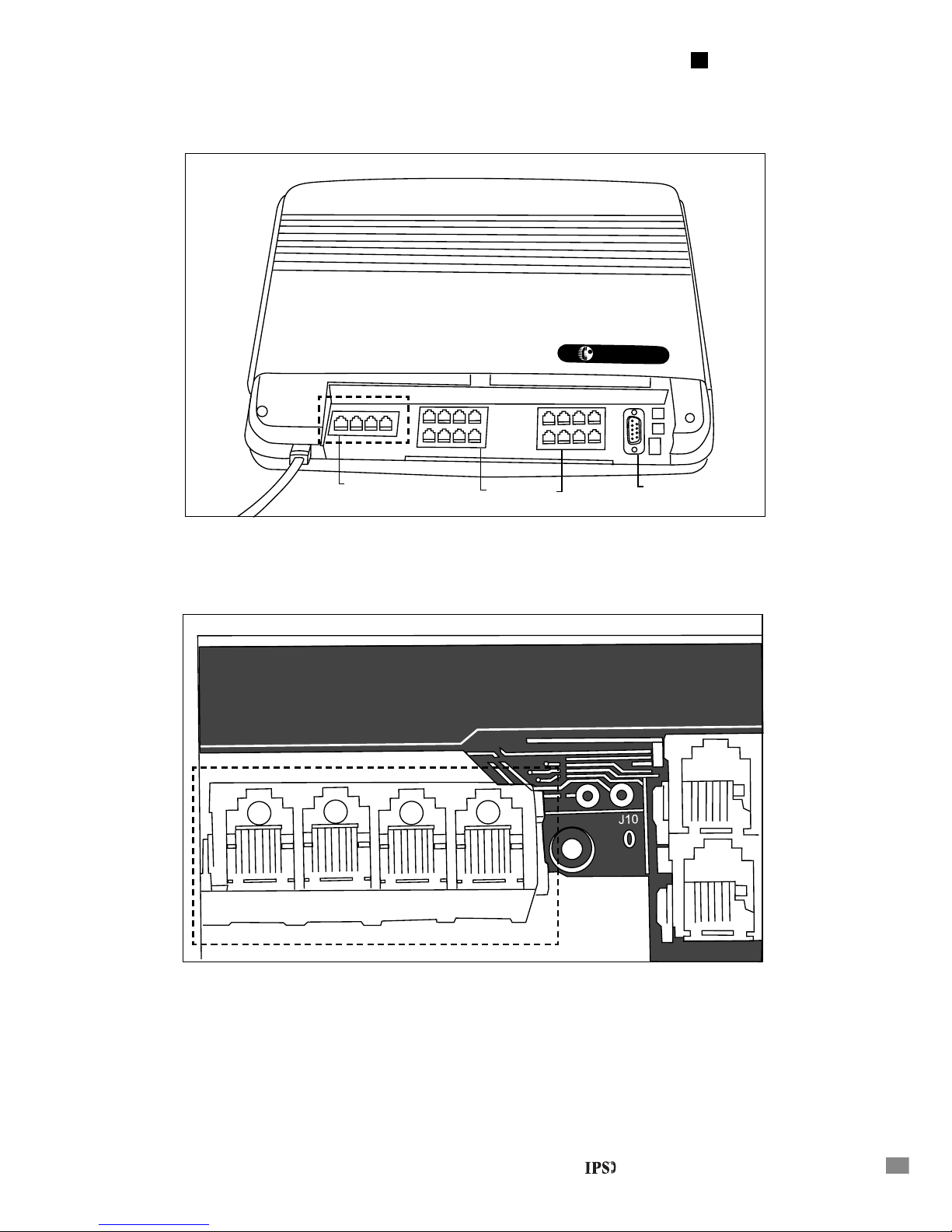
2. The block of four jacks from Central Offi ce lines is located at the far left of the IPS 416 model
unit (See Fig. A-1). On an IPS 308 model, it is a block of three jacks (located to the right of
the block of eight jacks for extensions).
Note: Notice that the order of the CO jacks for the 416 are numbered 4 to 1. (See Fig.A-2.)
The order of the 308 is 1 to 3.
3. Locate your fi rst published telephone number. It should have the telephone number written
on one of the RJ-11 connectors installed by the telephone company. Plug one end of the line
cord into the RJ-11 connector. Plug the other end into the “CO Line 1” jack on the IPS unit.
4. Repeat this process for the other CO lines. Record the line assignments for future reference.
Installing Your Phone System Unit
Chapter 2 - Installation Guide
Page 15
9
43
1
2
BBS Telecom
BBSBBS
Fig. A-1 IPS 416
CO Lines
Extensions
Peripherals
Fig. A-2 IPS 416 CO Lines
Installing Your Phone System Unit
Chapter 2 - Installation Guide
Page 16

10
About Wiring For Your Internal Phone Lines (Extensions)
For proper use and installation of your IPS system, your internal phone wiring for the extensions
must be wired in a “Home Run” confi guration. Virtually all offi ces are wired in this manner, but
few homes are. Most homes are wired in a confi guration referred to as “Loop Through”. To test:
If you can pick up any telephone in your house and get the same phone line, your home is wired
in a Loop Through confi guration. If you are installing the system at home, fi rst have your wiring
redone in a “Home Run” confi guration. The system will not function otherwise.
You will need each internal phone (extension) wire to have an RJ-11 connector on the end that
connects to the system and a 4-conductor jack at each extension location.
Connection Instructions: Internal Phone Lines (Extensions)
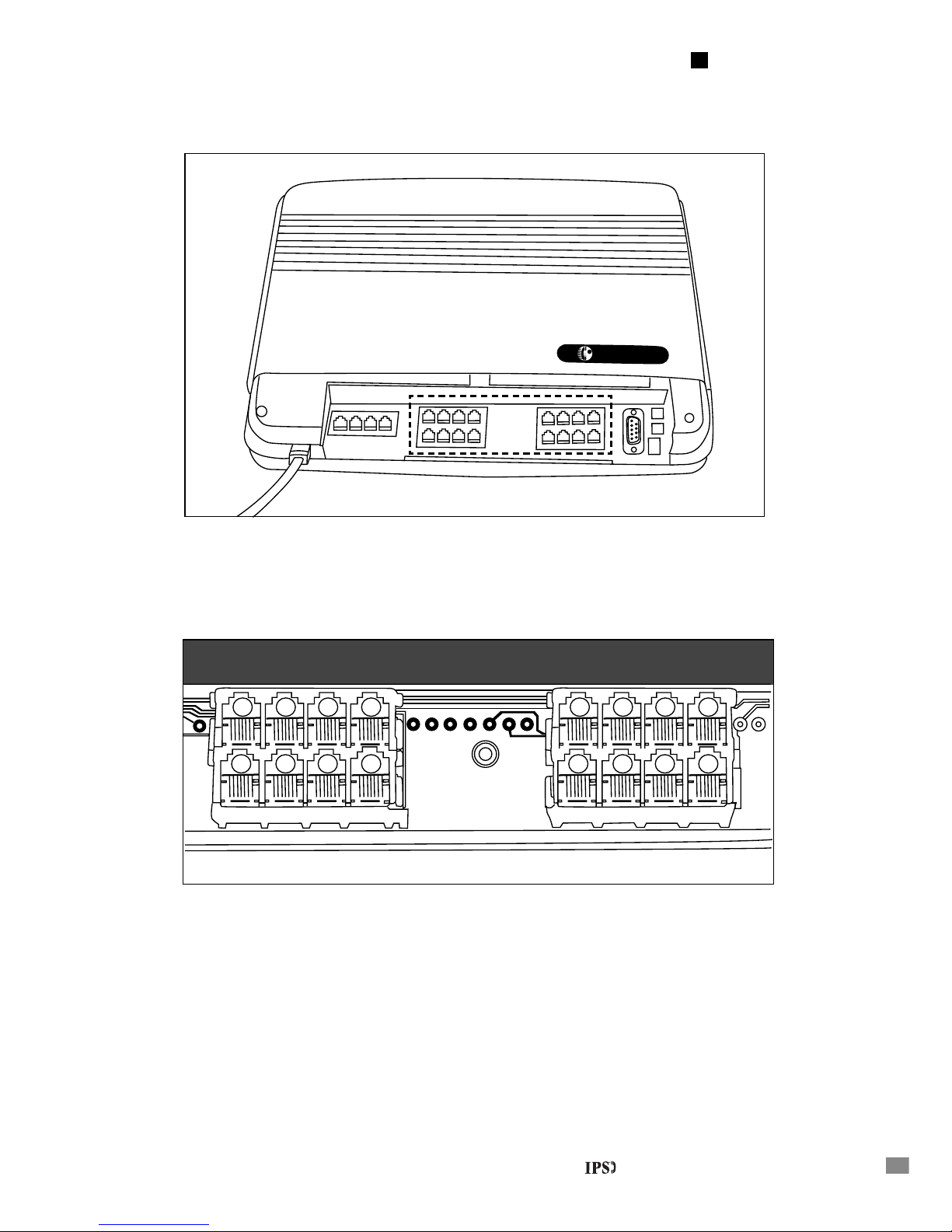
1. The block(s) of eight or 16 jacks for extensions are located beside the CO line jacks (See
Fig.D-1; the position of the jacks is reversed on the IPS 308 model.) The extension jacks
are numbered from 00 to 15 (See Fig.D-2) or 07 on the IPS 308 model. Select the extension
number that you want to assign to each of your extension locations.
2. Take the internal phone line you are assigning to extension 00. Plug it into the corresponding
jack. Repeat this step for each extension. Record the extension assignments for future
reference.
3. Plug the power cord into an electrical outlet. For safety reasons, this must be done only after
all lines and peripherals are installed and the phone jack access panel is securely fastened
using the retaining screw.
Recommended extension assignments are:
Extension 00 should be programmed as the system Operator/Receptionist station. Extension 15 on
the IPS 416 unit (Station 07 on the IPS 308 unit) is the System Manager (programming extension).
Extension 01 to 14 on the IPS 416 unit (01 to 06 on the IPS 308 unit) may be programmed as a
BBS key telephone, a single line telephone, a door phone, voice mail port, answering machine
extension, or a fax machine station.
Installing Your Phone System Unit
Chapter 2 - Installation Guide
Page 17
11
BBS
Telecom
BBSBBS
Fig. D-1 IPS 416
Fig. D-2 IPS 416 Extensions
00
06
05
04
03
02
01
07
08
09
10
11
12
13
14
15
To
Telephone
3
7
8
12
J12
Installing Your Phone System Unit
Chapter 2 - Installation Guide
Page 18
12
Wiring Central Offi ce Lines (CO)
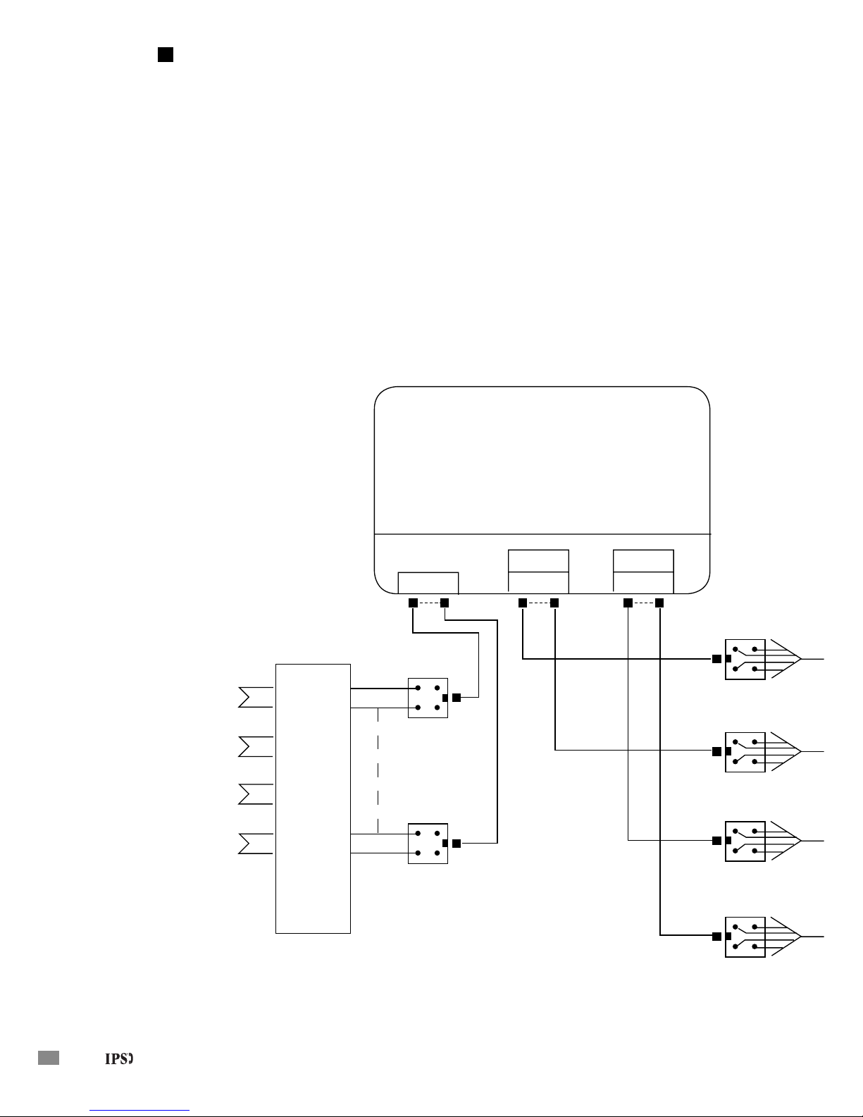
Depending on who may have installed the CO “Terminal Block,” and your incoming CO lines,
there may or may not be modular jacks to connect the 2 conductor (single pair) line cords to the
CO terminal block.
If not, you may want to connect the modular jacks and RJ-11’s (not included with system) as
shown in the diagram.
If you are familiar with the wiring of telephone equipment, you may choose to wire directly from
the CO ports of the system to the terminal block.
YG
BR
YG
BR
YG
BR
YG
BR
T
R
C01
T
R
C02
T
R
C03
T
R
C04
CENTRAL OFFICE (CO)
TIP & RING
CO TERMINATOR BLOCK
(CO)
2-CONDUCTOR LINE
CORDS
YG
BR
YG
BR
( EXT)
4-CONDUCTOR LINE CORDS FOR
KEY TELEPHONES, OTHERWISE,
USE 2-CONDUCTOR CORDS
Installing Your Phone System Unit
Chapter 2 - Installation Guide
Page 19
13
Wiring Internal Lines (Extensions)
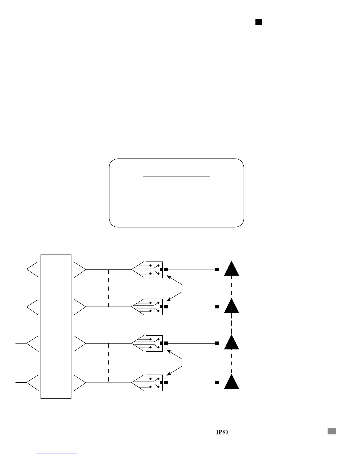
At most installations for extension wiring, the modular jacks as shown in the diagram will not be
present by the extension “Terminal Block.”
As with the wiring of the CO lines, you may add the modular jacks and RJ-11’s or wire directly
from the system to the terminal block for the extensions. With the wiring of extensions, you
will need cable and connections for 4 conductor (two pair) line cords for key telephones and
connections for 2 conductor (single pair) line cords for all other phone types.
G
BR
Y
G
BR
Y
G
BR
Y
G
BR
Y
W/B
B/W
W/O
O/W
(EXT’S
00-07)
W/B
B/W
W/O
O/W
W/B
B/W
W/O
O/W
(EXT’S
08-15)
W/B
B/W
W/O
O/W
EXT TERMINATOR BLOCK
(EXT)
4-CONDUCTOR LINE CORDS FOR KEY TELEPHONES,
OTHERWISE, USE 2-CONDUCTOR CORDS
EXT 15
EXT 08
EXT 07
EXT 00
WALL JACKS
WALL JACKS
(G) Green White/Blue (W/B)
(R) Red Blue/White (B/W)
(B) Black White/Orange (W/O)
(Y) Yellow Orange/White (O/W)
Color Code Connections
Installing Your Phone System Unit
Chapter 2 - Installation Guide
Page 20
14
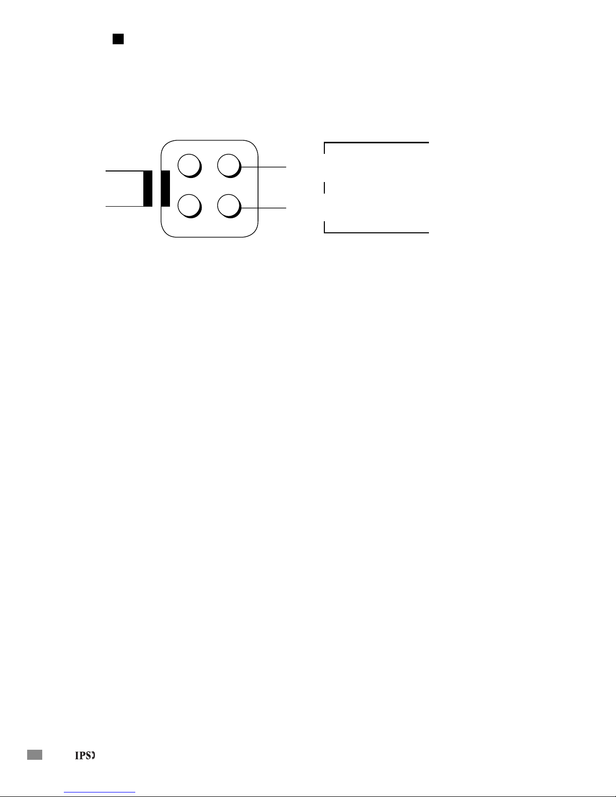
Single Line Telephone Wiring
Single pair (2 conductor) line cord connections:
For all extensions except those connected to key telephones, use only a 2-wire and not a 4wire connection. Some older telephones may use the outer two wires, which can disrupt either
the operation of the phones or the operation of key telephones at other locations. Some of the
equipment that will require a single pair (2-wire) line cord are: Electronic single line phones, door
phones, fax machines, or answering machines.
Some fax and answering machines require a longer ringing time for the machines to recognize an
incoming call. To adjust for this extended ring time you may want to program these stations with
Distinctive Ringing feature. The Distinctive Ringing feature will allow you to change the ringing
pattern of your extension equipment.
To change the ringing pattern:
1. Plug in a single line telephone set at the extension location
2. Lift the handset and dial “4711”
3. The extension is now programmed for a long ring pattern
Some single line telephones are polarity sensitive. If you go off-hook, and cannot break CO dial
tone, your phone is polarity sensitive. Reversing the White/Blue, Blue/White pair should correct
the problem.
Y G
B R
To Phone
2 Conductor
Line Card
White/Blue or
Green Wire
Blue/ White or
Red Wire
Cable
Installing Your Phone System Unit
Chapter 2 - Installation Guide
Page 21
15
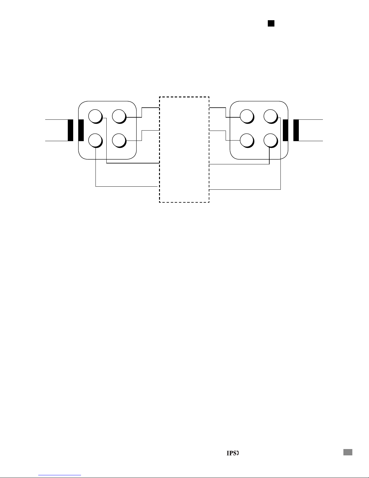
Key telephone wiring problems
1. If the key telephone has no response when you press any of its key:
The extension port that the key telephone is plugged into needs to be programmed as a Key
Telephone extension. This can be done by using the confi guration program on a personal
computer or from the System Manager’s extension.
2. If the key telephone does not operate at all:
The key telephone WILL NOT work if the polarity is Reversed! The polarity of the White/
Orange, Orange/White wires is VERY IMPORTANT. If the key telephone does not work,
try changing the positions of the White/Orange, Orange/White wires on that key telephone’s
extension port jack.
Key Telephone Wiring
G Y
R B
White/Blue or
Green Wire
Blue/ White or
Red Wire
Cable
Y G
B R
Line
Cord
Line
Cord
White/Orange
or Black Wire
Orange/White
or Yellow Wire
Telephone Equipment
(BBS IPS Unit Location)
Extension Location
(O ce or Room)
Installing Your Phone System Unit
Chapter 2 - Installation Guide
Page 22

16
Connecting Optional Peripherals
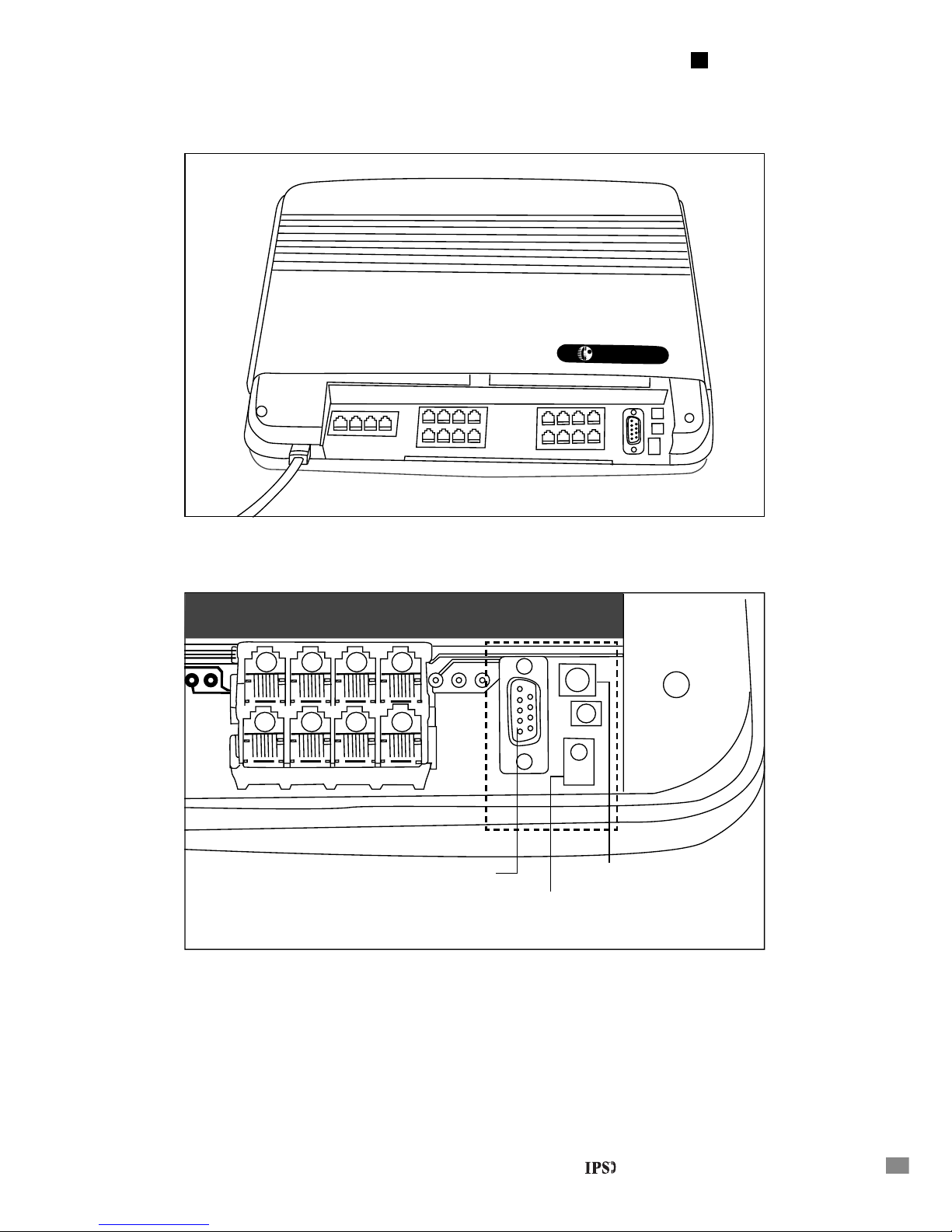
Peripherals are connected to the three special-purpose jacks located on the far right of the unit (See
Fig.E-1). You will need to obtain the wires necessary to connect your peripherals to these jacks.
Please consult the system guide for descriptions of the features that require these peripherals. If
you won’t be using the feature, you won’t need the peripheral.
WARNING:
For safety reasons, power must be off before connecting peripheral equipment.
Music On Hold (MOH)
Any external music source can be used to connect Music On Hold to the IPS system. You will
need to plug your music source unit into the RCA jack labeled “External Music” (See Fig.E-2).
The IPS system has an internal computer-generated music melody source for its Music On Hold.
This internal music source is disabled when the RCA mini plug is inserted into the “External
Music” jack. When an unconnected mini plug is inserted into the “External Music” jack and an
outside call is placed on hold, the caller will only hear silence.
External Paging / Common Audible Ringing
To have external paging and to have incoming calls ring over the paging system, plug your paging
system connector into the RCA jack labeled “Pager”. (See Fig.E-2)
Computer / Printer
The connection from the IPS system to a computer is made through the Computer/Printer
(RS232C) port (See Fig.E-2). To make the connection to a computer, you will need a straight (not
a null Modem) RS232 cable. The RS232 cable is connected from your computer/printer to the
jack labeled “RS232” (See Fig.E-2).
Your computer/printer needs to be able to receive information which is sent serially on an
RS232C compatible line at a rate of 9600 baud, 8 data bits, 1 stop bit, no parity. (see page 89 for
details on the RS 232 applications)
Installing Your Phone System Unit
Chapter 2 - Installation Guide
Page 23
17
BBS T
elecom
BBSBBS
Fig. E-1 IPS 416
Fig. E-2 IPS 416
08
09
10
11
12
13
14
15
8
12
J12
External MOH
Computer/Printer Paging/Common Audible
Installing Your Phone System Unit
Chapter 2 - Installation Guide
Page 24

18
RS232 Pin-out Diagram For Printer Connection
Pin Function
1 No Connection
2 Data out of IPS
3 Data into IPS
4 Data Terminal Ready (Connected to Pin 6 on IPS)
5 Ground
6 Data Set Ready (Connected to Pin 4 on IPS)
7 Request to Send (Connected to Pin 8 on IPS)
8 Clear to Send (Connected to Pin 7 on IPS)
9 No Connection
Checking The System For Proper Operation
After all the necessary extension wiring is properly connected, replace the phone jack access
panel and fasten it using the retaining screw. Plug the IPS unit in the A.C. outlet.
Test each extension
1. Plug a single line telephone into the RJ-11 connector at the extension location and listen to the
system dial tone.
2. Call another extension and listen for a ring.
3. Dial “9”, then listen for an outside dial tone.
If a dial tone is not heard and/or dialing cannot be performed, check the wiring at the jack for that
extension. For all extensions except those connected to key telephones, use only a 2-wire and not
a 4-wire connection. Do not connect the second pair. Some older telephones may use the outer
two wires which can disrupt the operation of the phones or disrupt the operation of key telephones
at other extensions. If the connection is good, it is possible that the telephone you are using is
polarity sensitive. Please reverse the wiring at the terminal block for the problem extension. A dial
tone should now be heard and you should be able to dial.
Installing Your Phone System Unit
Chapter 2 - Installation Guide
Page 25

19
Test each outside line
Use a single line telephone at any extension. For each line, dial the testing code from the chart
below. You should hear CO dial tone. Attempt to dial a phone number. If the call goes through,
the line has been properly connected.
For Line 1 Dial “61”
For Line 2 Dial “62”
For Line 3 Dial “63”
For Line 4 Dial “64”
CONGRATULATIONS!
YOUR UNIT IS NOW FULLY INSTALLED.
Installing Your Phone System Unit
Chapter 2 - Installation Guide
Page 26

20
Troubleshooting Tips
If your system is not working, check the following:
1. Has the telephone company installed your Central Offi ce (Outside Lines)?
2. Is your IPS unit plugged into the electrical outlet? Does the electrical outlet have voltage
going to it?
To check this, plug a radio, lamp, or any other electrical appliance into the outlet to see if the
appliance works.
3. Are all the RJ-11 connectors properly and securely connected?
4. Have all the key telephones been programmed for Key Telephone operation?
(See Chapter 3 to 5)
Single extension troubleshooting tips
If one extension is not working, check the following:
Plug a single line telephone set that you know works properly into the extension jack location at
the IPS unit. Lift the handset and listen for the system dial tone. If a dial tone is not heard, check
the connections on the jack. There could be a fault with the IPS unit. If a dial tone is heard, there
is a possible problem with the wiring from the IPS unit to the extension’s location.
Central Offi ce (Outside Line) troubleshooting tips
If the Central Offi ce line is not working, you may have exchange cable or system trunk port
problems. To test the CO lines you will need a single line telephone set. Now go to where your IPS
unit is installed and locate where the telephone company brought your Central Offi ce lines into the
building. If needed, this can be done by tracing the line cord that is plugged into your IPS unit’s
CO 1 port to the telephone company’s jack. Remove the line cord from the telephone company’s
RJ-11 jack. Plug the single line telephone into the jack. Lift the handset of the telephone set and
listen for dial tone. If a dial tone is heard, the trouble IS NOT with the telephone company. Check
all jack connections, check that all line cords are securely connected, and check the programming
to ensure that the CO line is enabled.
If the unit still does not seem to be working, please contact your local IPS distributor.
Troubleshooting Tips
Chapter 2 - Installation Guide
Page 27

21
Power failure note (Only for use with single line telephones)
If power to the unit fails, the system will not work as usual. The unit does not have an internal
backup power source.
However, it is programmed for backup protection. In the event of a power failure, extensions
00 and 01 become directly connected to outside lines 1 and 4 (for IPS 308 model, lines 1 and
3). A single line telephone must be connected at extensions 00 and 01. You will then be able to
receive and make calls as usual. All other extensions and outside lines will be inoperable until
power returns.
Troubleshooting Tips
Chapter 2 - Installation Guide
Page 28

23
Functions Of
Chapter 3
IPS System
Page 29
24
Preparing To Program
7832
Before entering the system program features, take some time to look over the different options
you have in setting up an extension as “System Manager”.
Designate An Extension For System Manager
All programming functions in this guide must be performed from the programming extension.
Initial programming of the IPS system must be done from extension #15 (or extension #07
for IPS 308). This extension should be assigned to the person who will program the system
and serve as System Manager for the offi ce.
NOTE: The Auto-Attendant message must be recorded from extension #15 (or #07 for IPS 308).
It cannot be recorded from extension #00.
The default programming extension is preset as extension #15 (or #07 for IPS 308). You have the
option of changing it to extension #00. This may be desired if the Operator is at extension #00 and
you want the Operator to also serve as the System Manager.
7833
To change the programming extension to #00:
At the System Manager’s extension, lift the handset and enter “7832”.
Pause for confi rmation tone. Hang up or continue programming.
To set the programming extension to #15 (#07 for IPS 308):
At the System Manager’s extension, lift the handset and enter “7833”.
Pause for confi rmation tone. Hang up or continue programming.
Choosing The Programming Mode – With or Without Password
With the default settings, the System Manager is required to enter a 6-digit password from their
extension to place the IPS in the programming mode. The password is entered by dialing the
code ‘761’, followed by a 6-digit password (The default value of password is ‘123456’). In
this mode, the System Manager can enter any programming codes. The password requirement
prohibits unauthorized persons from changing the programming. It can also reduce the likelihood
of accidental changes in the confi guration.
Preparing To Program
Page 30
25
If desired, you can remove the password entry requirement. This may be desirable for installations
where security is not an issue. It is, however, strongly suggested that the password be used so
that an accidental dialing sequence does not alter the system programming. For instance, if the
System Manager forgets to dial ‘9’ (or ‘0’) to make an outgoing call and then dials a number
sequence beginning with a ‘7’, they could be accidentally entering a programming command.
7849
7848
To allow programming without the entry of a password:
At the System Manager’s extension, lift the handset and enter “7849”.
Pause for confi rmation tone.
To require the entry of a password to enter programming mode:
At the System Manager’s extension, lift the handset and enter “7848”.
Pause for confi rmation tone.
Programming Tips
• All programming described in this guide must be performed in the programming
mode (see “Entering The Programming Mode Password”, page 28) and performed from the
programming extension (see “Designate An Extension For System Manager”, page 24).
• We recommend that the programming extension be assigned to the person who will act as
System Manager for the offi ce.
• If a desired feature is preset in the “enabled” mode, no programming is needed unless you
want to disable the feature.
• If the fi nal step in an operation reads “hang up”, you must do so for the programming to register .
• If the fi nal step reads “hang up or continue with programming” you can stay in the programming
mode and proceed directly to programming another feature.
• You probably will want to program a number of features in one sitting. However, please be
aware that you will be automatically “bumped” from the programming mode if you hang up
for more than two seconds.
• This guide can be used with both the IPS 416 and IPS 308 models of the BBS Hybrid Key
System. The IPS 416 accommodates up to 4 outside lines and 16 extensions numbered as #00
to #15. The IPS 308 accommodates up to 3 outside lines and 8 extensions numbered as #00
to #07. This guide is written to the capabilities of the IPS 416 model, with notes as necessary
for the IPS 308 model.
Chapter 3 - Functions Of IPS System
Preparing To Program
Page 31

26
Factory Default Settings
Password Entry for Programming Mode Required
System Mode Password 123456
Programming Extension #15 (#07 for IPS 308 model)
Basic Features
RS232C Mode System Mode
Call Follow Me Enabled
Require “Star” key before user programming Disabled
Operator Extension Extension #00
Advanced System Features
Direct Access to Extensions (DISA or Auto-Attendant) Disabled
Direct Outward Station Access (DOSA) Disabled
Automatic Day / Night Switching Disabled
Voice Announcement Message Not Recorded
Call History Memory Cleared
Call Records Format Short Format
Toll Restriction (Call Barring) Disabled
Hunt Groups Disabled
Key Telephone Clock Display Mode 24-Hour
Outside Line Features
To Access Outside Lines Dial “9”
Incoming Call Mode All Standard Incoming Lines
Incoming Call List Extension 00 to 15 in that order
Outgoing Call Group List Outside Line 1 to 4 in that order
Tone (DTMF) Dialing Enabled
Incoming Call Ring Over Paging System Disabled
Recognition of Incoming Fax Tones Disabled
Switch-hook to Outside Line Allowed
Clear Forward and Polarity Reversal Detection Disabled
Metering Pulse Detection Disabled
Rollover of Unattached Calls to Operator
Caller ID Detection Disabled
All Timing Parameters Default Values
Preparing To Program
Chapter 3 - Functions Of IPS System
Page 32

27
Extension Features (for all extensions)
Phone Type All ordinary phones, key telephones or door phones
Automatically access outside line Disabled
Call Transfer/Hold Allow
Call Hold Retrieval Allow
Call Break-in Disallow
Rollover Extension Assignments None Set
Emergency Alarm Disallow
Paging Groups None Assigned
Caller ID Display on IVT-16D key telephone Enabled
Extension Numbering Assigned Number is Physical Extension Number
When You Reset The System To Default Values:
All features are reset to the factory default settings. These will be the same as the values on your
new system. In addition:
• All call forwarding is cleared.
• All alarms are cleared.
• Call history memory is erased.
• Extensions assigned to call barring (toll restriction) tables are cleared, but contents of the call
barring tables are not affected.
• Speed dial numbers are not affected.
• Your voice announcement message is not affected.
Preparing To Program
Chapter 3 - Functions Of IPS System
Page 33
28
Entering The Programming Mode Password
If you are required to input a password to enter the programming mode, the following password
command will be used.
2. Enter the 6-digit password (Default = “123456”).
Pause for confi rmation tone.
Changing The Programming Mode Password
If you are requiring the System Manager to input a password to enter the programming mode, you
may change the password if, for security reasons, you do not want unauthorized people changing
the system settings. The default value of the password is ‘123456’. To change the value:
1. At the System Manager’s extension, lift the handset and enter “761”.
4. Pause for confi rmation tone.
Hang up or continue programming.
1. At the System Manager’s extension, lift the handset and enter “761”.
Followed by the current 6-digit password (Default = ‘123456’).
Pause for confi rmation tone.
2. Enter “762”.
3. Enter the new 6-digit password.
Then enter the new 6-digit password again.
761
“Password”
761
762
“Password”
Preparing To Program
Chapter 3 - Functions Of IPS System
Page 34
29
Resetting The System To Default Values
This command will reset all features on the system to default values. Please see the default
settings list on page 26 which shows what the settings will be for all features after you perform
this command.
Resetting the system to default values allows you to start from a “clean state” when reprogramming
the system after values have been changed.
7873
To reset the system to default values:
1. In the programming mode, enter “7873”.
Pause for the confi rmation tone.
2. Hang up or continue programming.
Preparing To Program
Chapter 3 - Functions Of IPS System
Page 35

30
Confi guring The Extensions
Choices When Programming The Extensions
Each extension must be individually defi ned in the way that best suits your needs. The options to
be decided upon are described below. These choices are programmed for the extension using the
commands given on the following pages.
1. What type of the phone will be connected to the extension?
An extension can be connected to an ordinary phone, a BBS key telephone, a fax machine, or
a door phone. (A door phone is an intercom at the outside door of your offi ce, which visitors
use to reach an operator. See page
34 for further details.) The system needs to know the phone
type to communicate properly.
Almost all ordinary phones with electronic ringers will work on the system, including most
cordless phones. Phones with mechanical (bell) ringers will function but will NOT ring
properly. Most answering machines, either tape or digital based will work with the IPS.
Most Voice Mail units with analog interfaces will work but they may require some additional
confi guration.
2. Which special feature do you want to allow the extension?
• Call Hold / Transfer: Allows the extension to put an outside call on hold or transfer an
outside call to other extensions. This capability may not be withheld from key telephones.
• Call Hold Retrieval: Allows retrieving a call placed on hold at another extension. This
capability may not be withheld from key telephones.
• Rollover Extension: Typically a voice mail or answering machine. (See “Rollover
Extensions – Advanced Topics”, page
70)
• Exclusive Answering Machine Privilege: Allows this extension to have a dedicated
answering machine on the next numerical extension. (See “Rollover Extensions – Advanced
Topics”, page
70)
• Call Break-in: Allows “breaking in” or interrupting another extension’s phone call.
• Emergency Alarm: Allows an extension to generate an emergency alarm signal to other
extensions.
• Paging Groups: Allows a key telephone or a door phone at the extension to be part of a
paging group.
Con guring The Extensions
Page 36

31
• Caller ID Display: Allows an IVT-16 series key telephone to display the incoming Caller
ID information.
• Automatic Outside Line Seize: Allows an extension to automatically connect to an outside
line when they lift their handset without dialing ‘9’ (or ‘0’). If the person at that extension
wants to make an intercom call or use other IPS functions, they can simply switch-hook
before dialing any digits to drop the outside line and connect to the IPS dial tone.
3. Do you want to give new numbers to the extension?
Each extension is automatically given a number by the system. This is the number on the
jack at the unit into which the extension line is plugged. The numbers are ‘00’ to ‘15’ for the
IPS 416 and ‘00’ to ‘07’ for the IPS 308. However, it may be more logical to give your lines
different numbers (e.g. ones that correspond to offi ce or room numbers).
NOTE: Even after you assign new numbers, the extension numbers on the jacks (‘00’ to ‘15’) still
need to be used for all system programming where a “2-digit extension number” is required. The
new extension numbers you assign are used when:
• Making intercom calls,
• Transferring outside calls to another extension,
• Entering an extension number in the Auto-Attendant (or DISA) mode,
• Forwarding calls to another extension,
• And turning on or off the message lamp of another extension.
If Hunt Groups are used (see “Hunt Groups”, page
61), the extension numbers 122, 133, 144, and
155 are reserved. You may not assign an extension to use one of these numbers.
Con guring The Extensions
Chapter 3 - Functions Of IPS System
Page 37
32
Programming The Extensions
The confi guration settings for each extension must be programmed separately. The programming
procedure is simple if you take it step-by-step. First, decide on the codes you want to enter for
each extension. Write the code for each of your choices in the table provided on page 34. Then
program one extension at a time. You must complete all steps for each extension before starting
on the next one. The “*” mark indicates the default value of each setting.
75
1. In the programming mode, enter “75”.
2. Enter the 2-digit extension number (“00” to “15”).
3. Enter the code for the phone type and features:
0 ordinary phone (with no special features)
* 1 ordinary phone + enable call hold retrieval
2 key telephone
3 key telephone + enable call hold retrieval
4 ordinary phone + rollover extension
5 ordinary phone + rollover extension + enable call hold retrieval
6 key telephone + rollover extension
7 key telephone + rollover extension + enable call hold retrieval
4. Enter the code for other features:
0 no additional features
* 1 enable call transfer / hold
2 enable call break-in
3 enable call transfer / hold + call break-in
4 enable emergency alarm
5 enable call transfer / hold + emergency alarm
6 enable call break-in + emergency alarm
7 enable call transfer / hold + call break-in + emergency alarm
Con guring The Extensions
Chapter 3 - Functions Of IPS System
Page 38
33
5. Enter the code for paging and door phone assignment.
Door Phone Member of
Paging Group:
*0 No 1 Yes 2 No 1
3 Yes 1
4 No 2
5 Yes 2
6 No 1 and 2
7 Yes 1 and 2
6. Enter the code for automatic connection to an outside line, exclusive
answering machine privilege, and Caller ID Enabling.
Automatic Exclusive Display of
Outside Line Answering Caller ID
Connection Machine Privilege Privilege
*0 No No Yes
1 Yes No Yes
2 No Yes Yes
3 Yes Yes Yes
4 No No No
5 Yes No No
6 No Yes No
7 Yes Yes No
7. Enter the new 2-digit number desired for the extension (or hang up or
re-enter existing extension number). Pause for confi rmation tone. Hang
up or continue programming.
Con guring The Extensions
Chapter 3 - Functions Of IPS System
Page 39

34
Extension Programming Summary – To program the extensions, enter the following:
Enter Extn. Step 3 Step 4 Step 5 Step 6 Step 7
“ 75 ” Number Code Code Code Code New
Number
75 00
75 01
75 02
75 03
75 04
75 05
75 06
75 07
75 08
75 09
75 10
75 11
75 12
75 13
75 14
75 15
Door Phone Operation Details
Any extension with the exception of extension #00 and the System Manager’s extension may be
confi gured to be a door phone. The BBS door phone may be placed at any location requiring a
hands free intercom station. In addition, any ordinary phone can be used as a door phone. When a
person at the door phone goes off hook (or presses the button on the BBS door phone), an alert ring
is heard on the fi rst four available extensions in the Standard Incoming List. This is similar to any
incoming call where the fi rst four available extensions in the Standard Incoming List are rung.
Any of the ringing phones may go off hook within the next 12 seconds to make a connection with
the Door Phone extension. More than one phone may connect to the Door Phone extension.
Con guring The Extensions
Chapter 3 - Functions Of IPS System
Page 40
35
Also, any extension can make an intercom call to a BBS door phone and they will be immediately
connected with the BBS door phone operating in a hands-free mode. An intercom call to an
ordinary phone connected to an extension programmed to be a door phone will ring normally.
Call Forwarding / Call Follow Me
Occasionally you may be required to work in an associates offi ce and will want to have your
phone forwarded to the other person’s offi ce. This feature is called “Call Forwarding” when you
enter the forwarding command from your extension. The feature is called “Call Follow Me”
when you issue the command from the extension to which you want the calls forwarded.
NOTE: In some installations, it may not be desirable to allow any user the ability to have calls transferred
to it by invoking the Call Follow Me command. For instance, a person at an extension in a hotel
could accidentally cause calls meant for the Operator to be directed to them.
7822
To disable the Call Follow Me function:
In the programming mode, lift the handset and enter “7822”.
Pause for the confi rmation tone. Hang up or continue programming.
A special exception to Call Forwarding is made to facilitate operation between a manager and
their secretary. If the manager has their calls forwarded to the secretary’s extension, the secretary
(but no one else) is able to make an intercom call to the manager’s extension or transfer an outside
call to the manager. Any other extension attempting such a call would have the call forwarded to
the secretary’s extension.
7823
To enable the Call Follow Me function:
In the programming mode, lift the handset and enter “7823”.
Pause for the confi rmation tone. Hang up or continue programming.
Con guring The Extensions
Chapter 3 - Functions Of IPS System
Page 41
36
Activating Programming Mode Using Star Key
All of the user programming commands begin with the ‘4’ or ‘5’ digit. In some installations, it
may be desirable to require that the user enter a ‘*’ key from the keypad of the phone before
entering one of these commands. This will prevent unintentional programming if a person dials a
phone number beginning with a ‘4’ or a ‘5’ but forgets to dial ‘9’ (or ‘0’) to connect to an outside
line. For instance, an extension could be accidentally placed in the Do Not Disturb mode or the
Day/Night setting could be changed. When this new parameter is set, dialing a ‘4’ or a ‘5’ without
fi rst dialing a ‘*’ digit will give an error tone.
Note that telephone sets with rotary dials cannot dial a ‘*’ digit. Thus, this setting should not be
enabled if there are pulse dialing telephones connected to the system.
7838
7839
To require a ‘*’ digit to be entered before a ‘4’ or a ‘5’:
At the System Manager’s extension, lift the handset and enter ‘7838’.
Pause for confi rmation tone.
To not require a ‘*’ digit to be entered before a ‘4’ or a ‘5’:
At the System Manager’s extension, lift the handset and enter “7839”.
Pause for confi rmation tone.
Con guring The Extensions
Chapter 3 - Functions Of IPS System
Page 42

37
Introduction: Confi guring Outside Lines
Now, we describe how incoming calls are handled in the IPS, begins the discussion of how to
confi gure the outside lines. Later, we describe the main confi guration commands, followed by
a discussion of Auto-Attendant or DISA (Direct Inward Station Access), then a description of
Outgoing Call Groups, and fi nally a discussion of DOSA (Direct Outward Station Access). And
also, in this chapter, there is a discussion of advanced topics concerning the setup of outside lines.
Overview: Choices In Handling Incoming Calls
Your fl exible Hybrid Key System offers many options for handling incoming calls. The choices
are as follows:
Standard Incoming Line or Private Incoming Line
The fi rst choice to be made for each outside line is whether you want the IPS to handle incoming
calls in a “standard” fashion or whether you want a particular line to be a “private incoming line”
and ring at an extension other than the Operator. Outside line #1 is always a Standard Incoming
Line while each of the others may be optionally confi gured to be Private Incoming Lines.
Auto-Attendant or Direct Inward Station Access (DISA)
Next, you can decide if you want the IPS to automatically connect incoming calls to a recorded
voice announcement which leads the caller through options for reaching individual extensions.
In this mode, the IPS can also be programmed to listen for an incoming fax tone and route the call
directly to the extension where the fax machine is located. This type of operation called AutoAttendant or DISA (Direct Inward Station Access).
The alternative to DISA is that the IPS will sense an incoming call and cause one or more
extensions to ring. In this case, a connection to the outside line will not be made until one of the
ringing extensions goes off hook.
Day Time And Night Time Handling Of Incoming Calls
The IPS can operate in the Day Mode or the Night Mode and each outside line can be set to
operate differently when in the two modes. For instance, an outside line can operate as a Standard
Incoming Line during the day and as a Private Incoming Line during the night. You can have an
incoming call ring at one group of extensions during the day and a different group of extensions
at night. You can also choose to have the Auto-Attendant (or DISA) mode operate during the day,
night, or both.
Technical SupportCentral Offi ce Lines – Incoming Calls
Central O ce Lines- Incoming Calls
Page 43

38
Incoming Call Alert Tone To The Paging System
Calls can be set up to ring over a paging system in addition to ringing at individual extensions.
Anyone can answer the call from any extension by dialing “3”. This is recommended for
businesses where employees are not seated at desks with phones, or where there is no dedicated
receptionist/operator.
Incoming Calls T o An Auto-Attendant System
If you are using an external Auto-Attendant / Voice Mail system, you can choose to have incoming
calls ring at the Voice Mail unit or at an operator’s extension. Simply enter the Standard Incoming
Line list to refl ect the extensions to which you would like to direct the incoming calls.
Defi ning The Standard Incoming Line
In most installations, all outside lines would be confi gured as a Standard Incoming Line. You will
fi rst defi ne a list of extensions which will ring when an incoming call is detected. You might also
choose to defi ne a second list of extensions which will ring when an incoming call is detected in
the Night Mode.
The operation of an outside line confi gured to be a Standard Incoming Line is as follows. When
an incoming call is detected, the IPS checks the extensions starting at the top of the appropriate
(day or night) list to fi nd the fi rst available extension. This extension will start ringing. Zero to
nine rings later (see “Multiple Ringing Time”, page
101), the IPS will fi nd the next three available
extensions in the list and start to ringing. After 5 to 60 seconds have passed (see “Rollover On
Standard Incoming Calls Timing”, page
98), the IPS will ring an available Rollover Extension
(usually a Voice Mail unit or answering machine).
Additionally, all BBS key telephones with the ‘RP’ (Ring Position) indicator set will also ring
when incoming calls are detected on outside lines confi gured as Standard Incoming Lines.
Central O ce Lines- Incoming Calls
Chapter 3 - Functions Of IPS System
Page 44

39
The Operator Extension
One extension is designated to be the Operator. The Operator extension is used by the IPS in the
following ways:
• Any extension may dial ‘0’ (or ‘9’) to place an intercom call to the Operator or to transfer an
outside call to the Operator.
• The Day mode Operator only may issue a ‘56’ command or a ‘57’ command to manually
switch the IPS into the Night mode or the Day mode.
• An incoming call to an extension on a Private Incoming Line that goes unanswered will ring
the Operator extension if the Operator is not busy.
• A call left on hold too long will ring at the extension which placed it on hold. If that extension
does not answer or is busy, the call will ring at the Operator extension if it is not busy.
• A call parked at an extension will ring the Operator (or a Rollover Extension, as programmed
by the System Manager) if the extension at which the call is parked does not become available
or if the extension becomes available but does not answer when the phone rings.
• A blind transfer of an outside call to an extension which does not answer will ring the Operator
(or a Rollover Extension, as programmed by the System Manager) if the extension to which
the call is being transferred does not answer.
• If an incoming caller to an outside line operating in the Auto-Attendant (or DISA) mode
specifi es an extension which does not answer, the call will transfer to the Operator.
• If no input (either DTMF or a fax Calling Tone) is detected during a DISA call, the call will
ring at either the Operator or the fax extension, as programmed by the System Manager.
Central O ce Lines- Incoming Calls
Chapter 3 - Functions Of IPS System
Page 45
40
The Standard Incoming List – Which Extension Is The Operator
The fi rst (non-Rollover) extension in the Standard Incoming List is defi ned to be the Operator.
This means that if your Standard Incoming Line List directs incoming calls to an Auto-Attendant
/ Voice Mail, the Operator will be defi ned as the next extension in the list after the Voice Mail
extensions (because your Voice Mail extensions would be defi ned as Rollover Extensions). Since
there is a separate list for Day and Night operation, a different Operator extension can be defi ned
for each mode.
Entering The Standard Incoming List
730 or 790
1. In the programming mode, enter “730” for the Day mode list or enter
“790” for the Night mode list.
2. Enter 2-digit extension numbers (“00” to “15”) assigned to the Standard
Incoming List.
Enter all of the extension numbers in succession. You can assign up
to 16 extensions. Be sure to enter the extensions in the order you want
them to be searched.
3. Hang up.
Hanging up is necessary for the assignments to register.
Central O ce Lines- Incoming Calls
Chapter 3 - Functions Of IPS System
Page 46

41
Keep a record of your Standard Incoming List assignments. Write the 2-digit extension
numbers in the following table.
Extension Numbers in the Extension Numbers in the
Standard Incoming List, Standard Incoming List,
Day Mode Night Mode
Enter 730 790
1st (Operator):
2nd
3rd
4th
5th
6th
7th
8th
9th
10th
11th
12th
13th
14th
15th
16th
Central O ce Lines- Incoming Calls
Chapter 3 - Functions Of IPS System
Page 47
42
Private Incoming Lines
You may wish to confi gure one or more of the outside lines to operate as a Private Incoming Line.
This would allow an incoming call to ring at an extension other than the Operator. Outside lines 2,
3, and 4 may be defi ned as Private Incoming Lines. As such you can defi ne the list of extensions
which the IPS will search when an incoming call is detected on that line. Only one extension will
ring. This is different from outside lines defi ned as Standard Incoming Lines where more than one
extension can ring at the same time.
Entering The Private Incoming List(s)
1. In the programming mode, enter the code for the desired Private
Incoming List.
731 Outside Line 2, Day Mode List
732 Outside Line 3, Day Mode List
733 Outside Line 4, Day Mode List
791 Outside Line 2, Night Mode List
792 Outside Line 3, Night Mode List
793 Outside Line 4, Night Mode List
2. Enter 2-digit extension numbers (“00” to “15”) assigned to the Private
Incoming List.
Enter all of the extension numbers in succession. You can assign up
to 16 extensions. Be sure to enter the extensions in the order you want
them to be searched.
3. Hang up.
Hanging up is necessary for the assignments to register.
Central O ce Lines- Incoming Calls
Chapter 3 - Functions Of IPS System
Page 48

43
For non-DISA calls to a Private Incoming Line, the IPS will ring the fi rst available extension in
the appropriate (day or night) list. If the extension does not answer within the “Rollover After
Call to Extension” time, the call will start ringing at the next available extension in the Private
Incoming List, not including the extension which is currently ringing. This proccess will repeat
until the incoming caller hangs up and the ringer signal is no longer present. Thus, the fi rst two
available extensions in the Private Incoming List will alternately ring until the call is answered or
the ringer input goes away.
One typical confi guration would be to put the Operator as the second extension in a Private
Incoming List. If the Operator does not answer, the call will start ringing at an available Rollover
Extension. Another typical confi guration would be to put an answering machine or voice mail
unit extensions in the list. Since the IPS unit allows both Day mode and Night mode lists, you will
want to make sure that an answering machine or voice mail is the fi rst or second extension in the
night list so that calls received after hours will never go unanswered.
In any case, it is best that the Private Incoming List be fi lled with enough entries so that the call
always has a place to ring. If there is no available extension in the Private Incoming List, the call
will park at the fi rst extension in the list and give a beep signal to that extension if it is a single
line telephone every few seconds to inform them that a call is waiting.
Central O ce Lines- Incoming Calls
Chapter 3 - Functions Of IPS System
Page 49

44
Keep a record of the Private Incoming Line List. Enter the extension numbers for each
outside line confi gured as a Private Incoming Line:
Outside Line 2 Outside Line 3 Outside Line 4
Day Night Day Night Day Night
Enter 731 791 732 792 733 793
1st
2nd
3rd
4th
5th
6th
7th
8th
9th
10th
11th
12th
13th
14th
15th
16th
Central O ce Lines- Incoming Calls
Chapter 3 - Functions Of IPS System
Page 50
45
Setting Incoming Calls To Ring Over Paging System
This option allows incoming calls to ring over a paging system in addition to the operator.
Anyone can pick up an extension and press “3” to answer the call. This is useful in businesses
where employees are not seated at desks with phones, or where there is no dedicated receptionist/
operator. Outside lines must have the Auto-Attendant (or DISA) mode disabled for this feature to
work. Also, your paging system must be plugged into paging system jack of the unit.
7810
To enable a ringback tone over the paging system:
In the programming mode, lift the handset, enter “7810”.
Pause for confi rmation tone.
To disable a ringback tone over the paging system:
In the programming mode, lift the handset, enter “7811”.
Pause for confi rmation tone.
7811
Central O ce Lines- Incoming Calls
Chapter 3 - Functions Of IPS System
Page 51

46
Central Offi ce Lines – Programming
Choices In Confi guring Central Offi ce (CO) Lines
Each CO line should be confi gured so that it best suits your needs. The options that must be
decided upon are described below.
1. Do you want to dial ‘9’ or ‘0’ to access an outside line ?
You can choose either ‘9’ or ‘0’ as the code for user to dial when requesting an outside line.
2. Are you using this CO line ?
If you do not use all of the CO line ports of the system, then the vacant ports need to be
programmed as “Disable”. This will make sure the IPS does not allow any extension to
connect to this line.
3. How should an incoming call be answered ?
If desired, you may select DISA (Direct Inward Station Access) for answering incoming calls.
This feature is also called Auto-Attendant mode. In this mode, the IPS will answer (Day and
/ or Night) and prompt the incoming caller to enter the digits or code of the desired extension
or department that they wish to speak with. It is suggested that you read more about DISA on
page 37 and 50 before selecting this feature so as to better understand its function.
If you choose to use the line so that calls must be answered by an extension before the outside
line is seized, then you will need to enter the code for “No DISA”.
4. Does your CO line accept tone (DTMF) or pulse (rotary) dialing ?
Some older Central Offi ce switches can interpret only pulse or rotary dialing. Most newer
Central Offi ce lines can accept tone or DTMF (Dual-Tone Multi-Frequency) dialing. The IPS
will need to know how it should dial digits when it is dialing a speed dial number or redialing
the last number dialed. See “Tone or Pulse Dialing Details” on page 65 for a complete
discussion of the dialing mode.
5. Do you want to be able to send a “switch-hook” to the CO line ?
Some Central Offi ce features, such as Call Waiting, are enabled by sending a “Switch-hook”
or “Flash” to the Central Offi ce. Some Central Offi ce switches will reset the CO line and
give a new dial tone in response to a Flash signal. If a new dial tone is given, the caller could
bypass the Call Barring (Toll Restriction) protection as the system would not know that a new
dial tone was received. If this is a consideration, you may wish to disable the sending of the
“Switch-hook” signal to the CO line.
Central O ce Lines- Programming
Page 52
47
The system Flash signal is set at a default value of 480 ms. This default value should work
with most signaling requirement. If not, the timing duration of this signal may be changed
to work with the requirements suggested by the Central Offi ce for the features that they may
provide in your area. (see “Switch-hook (Flash) Timing”, page 94)
6. How do you want the incoming lines to ring ?
All incoming CO lines will ring into the system. This step is used to select the manner in
which you wish them to ring according to the use of the desired CO line. For each line, you
can choose to confi gure it to handle incoming calls according to the Standard Incoming Line
confi guration or you can confi gure it to be a Private Incoming Line.
7. Do you want the unit to automatically detect incoming FAXes ?
Each CO line can have an assigned FAX extension to allow the system to automatically
direct an incoming fax (when the fax tone is detected) to an extension where a fax machine is
connected. The CO line must be in the DISA mode to allow automatic FAX detection.
Dialing “9” To Access Outside Lines
The system is preset so that users dial “9” to access an outside line and dial “0” to make an
intercom call to the Operator. You may want to change the “9” to a “0” if this is the standard in
your area.
Note: If you confi gure the system so that “0” accesses an outside line, “9” will then directly dial the
operator. If “9” is the number for outside line access, then “0” will dial the operator.
7801
To access an outside line by dialing “0”:
In the programming mode, lift the handset, enter “7801”.
Pause for confi rmation tone. Hang up or continue programming.
To access an outside line by dialing “9”:
In the programming mode, lift the handset, enter “7800”.
Pause for confi rmation tone. Hang up or continue programming.
7800
Central O ce Lines- Programming
Chapter 3 - Functions Of IPS System
Page 53
48
Programming Outside Lines
Each outside line must be programmed separately. The programming procedure is quite simple if
you take it step-by-step. First, decide on the codes you want to enter for each line. Write the code
for each of your choices in the table provided on the next page. Then program one line at a time.
The default settings are marked with an asterisk (*).
739
1. In the programming mode, lift the handset and dial “739”.
2. Enter the line number (1 to 4).
(For IPS 308 model, 1 to 3.)
3. Enter the code for enabling the CO line and for Auto-Attendant
(or DISA) operation.
* 0 No DISA
1 DISA in day mode only
2 DISA in night mode only
3 DISA always
4 Disable this CO line
4. Enter the code for the desired dialing mode and switch-hook (fl ashing)
capability.
0 Pulse dialing, switch-hook not allowed.
2 Tone (DTMF) dialing, switch-hook not allowed.
4 Pulse dialing, switch-hook allowed.
* 6 Tone (DTMF) dialing, switch-hook allowed.
Central O ce Lines- Programming
Chapter 3 - Functions Of IPS System
Page 54
49
To keep a record of the programming of the outside lines, enter the following:
Enter Enter Step 3 Step 4 Step 5 FAX Pause
“739” Line # Code Code Code Extn.
739 1 Pause
739 2 Pause
739 3 Pause
739 4 Pause
5. Enter the code for the desired incoming ringing mode.
4 Private Incoming Line always.
1 Standard Incoming Line in daytime. Private Incoming Line
at night.
2 Standard Incoming Line at night. Private Incoming Line in
daytime.
* 3 Standard Incoming Line always.
6. Enter the 2-digit F AX extension (“00” to “15”) used for automatic FAX
detection.
(If automatic FAX detection is not used on this line, hang up.)
7. Pause for confi rmation tone. Hang up or continue programming.
Central O ce Lines- Programming
Chapter 3 - Functions Of IPS System
Page 55

50
Auto-Attendant (DISA) Feature
About DISA And Direct Caller Access To Extensions
Enabling the Auto-Attendant or DISA (Direct Inward Station Access) feature for outside lines
allows incoming callers to connect themselves directly to an extension. The optional Voice
Announcement module can be enabled to lead the caller through options for reaching individual
extensions. The IPS can also be programmed to listen for an incoming fax tone and route the call
directly to the extension where the fax machine is located.
Setting DISA as enabled or disabled is done as part of setting the command sequence for
“Programming Outside Lines” (see page
48). This is done separately for each line. You have the
option of enabling DISA at all times, during regular business hours (Day Mode), or after regular
business hours (Night Mode).
In the IPS, there is only one Voice Announcement module and one circuit to collect the digits
coming from the outside caller when the call is answered in the DISA mode. If two incoming
calls are received at the same time and both outside lines operate in the DISA mode, the second
incoming call will continue to ring and will not be answered until after the caller on the fi rst line
has made their DISA selection.
After the IPS answers the incoming call and the optional voice announcement module is playing
the recorded message, the incoming caller can dial:
‘0’: to call the Operator.
‘1xx’: to ring extension “1xx” where “xx” is the extension number (“00” to
“99”) assigned using the Confi gure Extension command (see page 3
2).
‘2’, ‘3’, ‘4’, or ‘5’: to ring the fi rst available extension in Hunt Group 2, 3, 4, or 5
(see page 61).
‘6’ or ‘7’: to invoke the DOSA feature (see page
59).
Auto-Attendant (DISA) Feature
Page 56
51
Recording A V oice Announcement
This command allows you to record an announcement to greet callers. The recording can be
made only from extension #15 (or #07 for IPS 308). (See “Designate An Extension For System
Manager” on page
24 if you need to change the programming extension to 15)
Time the length of your spoken announcement before recording it. If you want to record a very
short announcement, you can enter the digit ‘0’ at the end of your message which will cause the
IPS to ring the Operator.
Sample Announcement
“Hello, you have reached XYZ Corporation. To send a fax, press the start button on your fax
machine at anytime. If you are calling from a touch-tone phone, you may enter the extension
number of your desired party at any time. Press ‘2’ to place an order. Press ‘3’ for customer
service. Press ‘0’ to reach the operator. Press ‘106’ for accounting. Thank you.”
728
1. In the programming mode, enter “728”. Pause for the confi rmation tone.
2. Record your announcement by speaking into the handset. When you
have fi nished speaking, keep the phone off the hook until you hear a
confi rmation tone. This marks the end of the 20 seconds available. (If the
tone cuts you off, re-enter “728” and record a shorter announcement.)
3. Hang up or continue with programming.
Auto-Attendant (DISA) Feature
Chapter 3 - Functions Of IPS System
Page 57
52
Enabling The Voice Announcement
For an outside line operating in the DISA mode, the voice announcement module may be enabled
or disabled. Some hardware models do not have the voice announce module. This parameter must
be enabled to allow the IPS to play the voice announcement. If the voice announcement module is
not enabled, the incoming caller will hear silence after the IPS answers the call in the DISA mode.
7806
7807
To enable the Voice Announcement Module:
In the programming mode, lift the handset, enter “7806”.
Pause for confi rmation tone.
To disable the Voice Announcement Module:
In the programming mode, lift the handset, enter “7807”.
Pause for confi rmation tone.
Setting The Length Of The DISA Input Time
The length of the Voice Announcement recording is fi xed at 20 seconds. The length of time that
the system waits for the incoming caller to make a choice can be set at 25 seconds or 75 seconds
if the Voice Announcement module is enabled or it can be set at 6 seconds or 12 seconds if the
voice announcement module is not enabled.
To set the DISA input time at 75 seconds or 12 seconds:
In the programming mode, lift the handset, enter “7812”.
Pause for confi rmation tone.
To set the DISA input time at 25 seconds or 6 seconds:
In the programming mode, lift the handset, enter “7813”.
Pause for confi rmation tone.
7812
7813
Auto-Attendant (DISA) Feature
Chapter 3 - Functions Of IPS System
Page 58
53
What Happens After The DISA Entry
After the incoming caller has entered their selection on an incoming line operating in the AutoAttendant (or DISA) mode, the IPS will start ringing at an extension. While the extension is
ringing, the caller will either hear a ringback tone or the Music On Hold input.
7808
To enable the Music On Hold input after DISA input:
In the programming mode, lift the handset, enter “7808”.
Pause for confi rmation tone.
To enable the ringback tone after DISA input:
In the programming mode, lift the handset, enter “7809”.
Pause for confi rmation tone.
7809
If the caller specifi es an extension which is not available, they will hear a short busy signal. Then
the call will ring at the fi rst available extension in the appropriate incoming call group if the
outside line is confi gured to be a Private Incoming Line or it will ring as a Standard Incoming
Line if it is confi gured.
If the DISA call is directed to an extension which does not answer after 5 to 50 seconds, the call
will transfer to the operator (see “Rollover After Call to Extension” on pag
e 99). If the operator
does not answer after 5 to 60 seconds, the call will transfer to an available Rollover Extension (see
“Rollover On Standard Incoming Calls Timing” on pag
e 98).
Any external music source can be used to connect Music On Hold to the IPS system. You will
need to plug your music source unit into the RCA jack labeled “External Music” on the IPS. The
IPS system has an internal computer-generated music melody source which is disabled when
the RCA mini plug is inserted into the “External Music” jack. This music signal is heard by the
incoming caller when they are placed on hold.
Auto-Attendant (DISA) Feature
Chapter 3 - Functions Of IPS System
Page 59
54
What Happens If There Is No DISA Entry
If an outside line answers in the Auto-Attendant (or DISA) mode and the caller does not enter
any DTMF digits and no fax tone is detected, the IPS can transfer the call to either the operator
or to the designated fax machine. You should choose for these calls to go to the FAX extension
if this outside line is used mostly for receiving faxes. This is helpful since some fax machines do
not send the calling tone until after the called fax machine answers and thus the IPS cannot detect
the incoming fax tone.
You should choose for these calls to go to the “Operator” if the outside line is used mostly for
voice callers. A caller using a pulse dial telephone would not be able to enter any DTMF digits
and you would want this call be directed to the operator. (If the outside line is set to ring according
to the Standard Incoming Line defi nition, the “Operator” setting here will cause these calls to ring
extension(s) according to that defi nition. If the outside line is confi gured as a Private Incoming
Line, the “Operator” setting will cause these calls to ring at the fi rst available extension in the
private incoming call list for that outside line.)
To ring the operator if there is no DISA entry:
In the programming mode, lift the handset, enter “7856”.
Pause for confi rmation tone.
To ring the FAX extension if there is no DISA entry:
In the programming mode, lift the handset, enter “7857”.
Pause for confi rmation tone.
7856
7857
One option for a line which is to be used mostly for fax reception might be to program the outside
line to operate in the DISA mode during the day time with this parameter set to send calls with no
DTMF or FAX input to the operator. During the day time, the operator would hear either silence
or a fax tone and manually transfer the call to the FAX extension. In the night mode, the outside
line could be confi gured to be a Private Incoming Line, ringing only at the FAX extension.
Auto-Attendant (DISA) Feature
Chapter 3 - Functions Of IPS System
Page 60
55
Multiple Fax Extensions
If a fax tone is detected on an incoming DISA call, the IPS would normally try to transfer the
call only to the fax station associated with that outside line. In installations where you have more
than one extension with a fax machine, this parameter allows the call to be transferred to the Fax
extension assigned to any of the CO lines. This reduces the likelihood that an incoming fax call
will not have an available FAX extension to which it can be transferred.
7858
To allow a fax detected on an outside line to ring at a FAX extension
assigned to a different outside line:
In the programming mode, lift the handset, enter “7858”.
Pause for confi rmation tone.
T o allow a fax detected on an outside line to only ring at the F AX extension
assigned to that outside line:
In the programming mode, lift the handset, enter “7859”.
Pause for confi rmation tone.
7859
If an incoming fax is detected but there is not an available FAX extension, the call will ring at
the operator.
Auto-Attendant (DISA) Feature
Chapter 3 - Functions Of IPS System
Page 61

56
Central Offi ce Lines – Outgoing Calls
About Outgoing Call Groups
The purpose of the Outgoing Call Groups is to provide the optimal management of outgoing calls,
giving maximum outside line access to the users and extensions that need them most. The system
has the capability to defi ne up to 4 Outgoing Call Groups. Each group is a list of outside lines and
every extension is assigned to one of these four groups. When the extension dials ‘9’ (or ‘0’) to
make an outside call, the system uses the list to fi nd the fi rst available CO line.
Example: An offi ce with 4 outside phone lines, a fax machine, 10 employees in two departments,
and one top executive might create the following trunk groups:
FAX Group You may prefer that the FAX extension use only a certain outgoing line. You
could create an Outgoing Call Group which contains the preferred outside line
fi rst with other lines also available.
If you have an outside line dedicated solely for the use of the fax machine and
you do not want anyone to make voice calls on this line, you may want to connect
the fax machine directly to the outside line, bypassing the system.
Sales Group All extensions assigned to the sales staff might have access to all of the lines.
This provides them with maximum access to lines on which to make sales calls
– which is good for business!
Tech Group If this group needs to make fewer calls, they might be linked with only one or two
outside lines, keeping the rest free for sales calls.
Executive Optionally, the executive may want a dedicated phone line for their extension,
so that they always have a line available and can have a private number. The
disadvantage would be that other extensions are left with one less line for
outgoing calls.
Central O ce Lines- Outgoing Calls
Page 62
57
1. In the programming mode, enter “73”.
2. Enter the code for the Outgoing Call Group being created:
4 Outgoing Call Group #1
5 Outgoing Call Group #2
6 Outgoing Call Group #3
7 Outgoing Call Group #4
If you do not want any outside lines in this Outgoing Call Group, hang up.
3. Enter the line numbers of the outside phone lines(s) that are part of this
Outgoing Call Group. Enter one to four entries.
1 Outside Line #1
2 Outside Line #2
3 Outside Line #3
4 Outside Line #4 (IPS 416 model only)
4. Hang up
Hanging up is necessary if fewer than 4 outside lines were entered.
Defi ning Outgoing Call Groups
You can defi ne up to 4 Outgoing Call Groups. Each group can include from none to 4 (3 for IPS
308 model) outside lines. Each outside line can be included in more than one trunk group. The
order in which the line numbers are entered (in Step 3) will determine the order in which the
system searches them for availability when an extension dials ‘9’ (or ‘0’) to connect to an outside
line. If you want a certain line to be tied up the least (i.e., the fax line) but still available for outside
calls, enter it last.
73
Central O ce Lines- Outgoing Calls
Chapter 3 - Functions Of IPS System
Page 63
58
738
1. In the programming mode, enter “738”.
2. Enter the 2-digit extension number (“00” to “15”).
3. Enter the number of the Outgoing Call Group (“1” to “4”) to which this
extension is assigned.
4. Pause for confi rmation tone. Hang up or continue programming.
Assigning Extensions To An Outgoing Call Group
This feature links each extension to a specifi c Outgoing Call Group. It thereby defi nes which
outside phone line(s) the extension can use. Any number of extensions can be assigned to a given
group. This command must be repeated separately for each extension.
You could assign an extension to an Outgoing Call Group containing no outside lines which
would prohibit the extension from placing any outgoing calls.
With default settings, Outgoing Call Groups #1 and #4 contain CO lines #1, #2, #3 and #4 in the
order. Outgoing Call Groups #2 and #3 contain no CO lines. All extensions are assigned to use
Outgoing Call Group #1.
Central O ce Lines- Outgoing Calls
Chapter 3 - Functions Of IPS System
Page 64

59
Direct Outward Station Access (DOSA) allows an incoming caller to enter a password and be
connected to a different outside line within the system and make an outgoing call. The original
incoming call must be directed to a CO line which is programmed to operate in the DISA mode
(See “Choices In Confi guring Central Offi ce (CO) Lines” on page 46).
After the system answers the incoming call in the DISA mode, the caller should dial a “6” or
a “7”, followed by the 6-digit DOSA password. If the password entered matches the password
stored in memory, a connection will be made to the fi rst available CO line listed in Outgoing Call
Group #4 (See “Defi ning Outgoing Call Groups” on page 57).
If the incoming caller entered a “6”, the system must detect a DTMF digit within 35 seconds in
order to allow the connection to continue. If no digit is detected after 20 seconds, a beep tone
will be heard. When a digit is entered the beep tone will cease. Thereafter the beep tone will be
heard every 4 minutes and a DTMF digit must be entered within 15 seconds to continue the call.
This will prevent the situation where the incoming caller hangs up and the system is connected
to the CO line indefi nitely. In all cases, the call will be terminated in 15 minutes or when a Clear
Forwarding / Polarity Reversal signal is detected, if enabled.
If the incoming caller entered a “7” followed by the 6-digit password, the operation is exactly the
same as for a “6” except there will be no prompts for DTMF digits. This can facilitate fax and data
transfers via DOSA since it would be impossible to enter a DTMF digit during data transmission.
The “6” entry is still preferred for voice conversation so that the CO line can be released in a short
time after the conversation has ended.
If the outgoing CO line (to which DOSA is connected) is confi gured for pulse dialing, any digits
entered by the caller will also be output as pulses. This conversion of DTMF to pulses will continue
until either a “*” or “#” digit is entered. Thus the “*” or “#” are the preferred entry when responding
to the disconnect warning signal so that there will not be any pulses output on the CO line.
Direct Outward Station Access (DOSA)
Direct Outward Station Access (DOSA)
Page 65
60
7834
To enable DOSA:
In the programming mode, enter “7834”.
Pause for confi rmation tone.
To disable DOSA:
In the programming mode, enter “7835”.
Pause for confi rmation tone.
Enable Direct Outward Station Access (DOSA)
The DOSA function must be enabled by the System Manager to allow an incoming caller to enter
a password and be connected to a different CO line to make an outgoing call.
Entering The DOSA Password
The DOSA password must be specifi ed using this command.
Enter password:
1. In the programming mode, enter “764”.
2. Enter a 6-digit password.
Pause for confi rmation tone.
7835
764
“Password”
Direct Outward Station Access (DOSA)
Chapter 3 - Functions Of IPS System
Page 66
61
Four separate Hunt Groups can be implemented, allowing a person to dial a number which will
ring at the fi rst available extension of that group. This can be used for intercom calls or for
incoming DISA calls where the incoming caller can be prompted to “press 3 for sales, press 4 for
technical support, etc.”. There are four groups named as Hunt Group #2, #3, #4, and #5 and each
Hunt Group can contain 4 extensions. The Hunt Groups are accessed as follows:
To call an For intercom calls or to For an incoming
extension in: transfer an outside line: DISA caller:
Hunt Group #2 dial “ 122 ” dial “ 2 ”
Hunt Group #3 dial “ 133 ” dial “ 3 ”
Hunt Group #4 dial “ 144 ” dial “ 4 ”
Hunt Group #5 dial “ 155 ” dial “ 5 ”
If an extension in a Hunt Group desires not to receive calls temporarily, then they may forward
their calls to another extension or to a different Hunt Group. If an extension in a Hunt Group
desires not to receive calls for a period of time (i.e. out of the offi ce or vacation), then that
extension should enter the Do Not Disturb mode.
To Enable The Use Of The Four Different Hunt Groups
Hunt Groups must be enabled so that the Hunt Group codes will be recognized by the unit.
Hunt Groups
7854
To enable Hunt Groups:
In the programming mode, enter “7854”.
Pause for the confi rmation tone.
To disable Hunt Groups:
In the programming mode, enter “7855”.
Pause for the confi rmation tone.
7855
Hunt Groups
Page 67
62
795
1. In the programming mode, enter “795”.
2. You must assign 4 extensions per Hunt Group. Enter the 2-digit
extension numbers (“00” to “15”) of the 4 extensions that will be in
Hunt Group #2.
3. Repeat Step 2 for extensions in Hunt Groups #3, #4 and #5.
Pause for confi rmation tone.
Assigning Extensions To The Hunt Groups
This command allows you to specify the extensions in each of the Hunt Groups.
NOTE: If it is desired to have fewer than 4 extensions in any group, the number of one of the extension
members should be repeated more than once to fi ll all four places in the group list.
It is recommended that all four of the Hunt Group Lists be fi lled. This would prevent an incoming
caller from accessing a vacant group if they dialed the wrong Hunt Group number. If only using
two groups, then it may be best that the other two group extensions be entered as “00” (Operator)
or another extension that you wish to answer the calls.
The following table gives an example of how to use this command.
First dial “795”
• then dial “01 03 04 11” Hunt Group #2: Extension #1, #3, #4, #11
• then dial “05 06 06 06” Hunt Group #3: Extension #5, #6
• then dial “12 13 14 14” Hunt Group #4: Extension #12, #13, #14
• then dial “00 00 00 00” Hunt Group #5: Extension #0
• then pause for the confi rmation tone.
Keep a record of your Hunt Groups in the following table:
First dial “795”, then
Hunt Group #2:
Hunt Group #3:
Hunt Group #4:
Hunt Group #5:
Hunt Groups
Chapter 3 - Functions Of IPS System
Page 68
63
Automatic Day / Night Mode Switching
The operator extension can manually switch the system into Night mode by dialing “56” or into
the Day mode by dialing “57”. This command is only valid if issued from the Day mode operator
extension (see “The Standard Incoming List” on page
40). It is also possible for the system to
automatically switch from one mode to another at certain times of the day.
Day And Night Modes
7826
To enable automatic switching between modes:
In the programming mode, enter “7826”.
Pause for the confi rmation tone.
To disable automatic switching between modes:
In the programming mode, enter “7827”.
Pause for the confi rmation tone.
7827
If this automatic switching option is desired, the System Manager would need to inform the
daytime operator of feature commands “56” and “57”, plus the feature functions.
The IPS can be programmed to refrain from automatically switching into the Day mode on
days defi ned as weekends (Friday, Saturday, and/or Sunday). There may be times you want to
temporarily disable automatic switching into the Day mode on other days due to holidays and
long weekends. You can enter the manual switching commands (“56” and “57” from the Day
mode Operator’s extension) which disables automatic switching. At a later time you can re-enable
automatic switching to return to your normal schedule.
Day And Night Modes
Page 69
64
1. In the programming mode, enter “794”.
2. Enter the desired 4 digits to specify the hour (“00” to “23”) and the
minutes (“00” to “59”) at which the system switches into the Night
mode.
3. Enter the digit that specifi es the weekend day/days during which
automatic switching into the day mode is enabled.
0 Disable switching into Day mode on Friday, Saturday and Sunday.
1 Enable Day mode on Sunday only.
2 Enable Day mode on Saturday only.
3 Enable Day mode on Sunday and Saturday only.
* 4 Enable Day mode on Friday only.
5 Enable Day mode on Friday and Sunday.
6 Enable Day mode on Friday and Saturday only.
7 Enable Day mode on Friday, Saturday and Sunday only.
4. Pause for confi rmation tone.
Hang up or continue programming.
If Automatic Day/Night Switching is enabled, the IPS will automatically determine (upon
power up or Switching time changes) whether it should be in the Day or Night mode. For proper
operation, it is necessary that the time specifi ed for switching into the Day mode must be earlier in
the day than the time specifi ed for switching into the Night mode. Otherwise, improper operation
will result.
If the Operator enters the “56” or “57” command to manually change the operating mode,
automatic switching will be disabled and must be re-enabled by the System Manager (if desired)
by entering the “7826” command from the System Manager’s extension.
Automatic Day / Night Mode Switching Times
When the automatic Day/Night switching is enabled, the command to specify the switching times
are as follows:
794
Day And Night Modes
Chapter 3 - Functions Of IPS System
Page 70

65
Tone or Pulse Dialing Details
Each outside line can be set in the programming command to be a default tone (DTMF) or rotary
(pulse) dialing type. During speed dialing or redialing, digits will always be output in the tone
mode if the outside line is set to tone. If the outside line is programmed to dial in the pulse mode,
digits will be output as dial pulses until a star (‘*’) or a pound (‘#’) is encountered. Dialing will
then switch to the tone mode. The initial ‘*’ or ‘#’ digit will not be sent to the outside line.
In a simple connection from an extension to an outside line, extensions with ordinary phones are
treated differently than extensions with key telephones. An ordinary phone can send either DTMF
tones or pulses to the IPS. If the outside line is confi gured for tone dialing, the DTMF digits from
the phone simply pass through the IPS to the outside line. If the phone sends pulses, the IPS will
receive the entire digit and then output digit pulses onto the outside line using the pulse mode
timing programmed by the System Manager (see “Pulse Dialing Timing”, p
age 96). Note that
when an extension invokes the Last Number Redial command, the IPS will output DTM
F tones
since the outside line is confi gured for tone mode dialing, even if extension originally dialed the
number using pulse dialing.
If the outside line is confi gured for pulse dialing, the IPS can receive dial pulses from an ordinary
phone and will receive each entire digit and then output digit pulses onto the outside line. If the
phone is sending DTMF digits, the IPS will receive the DTMF digits and send dial pulses to the
outside line. Note that the DTMF tones sent from the phone will be passed through to the outside
line even though the IPS will also send dial pulses. The IPS will convert the DTMF tones into
dial pulses until a ‘*’ or a ‘#’ digit is encountered which will disable pulses from being sent to the
outside line for the duration of the call.
For extensions connected to key telephones, each key telephone has a TONE/PULSE key which
causes a light on the phone to be lit if the phone is in the pulse mode. In the pulse mode, digits
pressed are sent to the IPS in computer code and the IPS will send the equivalent dial pulses to
the outside line. Thus, unlike with an ordinary phone, DTMF tones are not passed through to the
outside line before the dial pulses are sent. In the tone mode, the phone sends the DTMF tones
which are simply passed through the unit to the outside line. Note that the default dialing mode
set for the outside line only affects speed dialing and redialing operations. If a key telephone
sends a DTMF tone to an outside line which is confi gured to operate in the pulse mode, the IPS
will only pass the DTMF digit dialed and will not end dial pulses. The PAUSE key on the key
telephone can be pressed during dialing which will insert a 2-second pause during a subsequent
Last Number Redial.
Central Offi ce Lines – Advanced Topics
Central O ce Lines – Advanced Topics
Page 71
66
Disconnect Supervision: Polarity Reversal / Clear Forwarding
Some Central Offi ce switches signal the unit when the remote party in an outside call has
disconnected from the line. For example, if an outside call is placed on hold and during that time
the outside party hangs up, the system will know to release the line. The IPS supports two types
of signaling. With Clear Forward signaling, the Central Offi ce removes the battery feed from
the Tips and Ring lines to signal that the remote party has disconnected. With Polarity Reversal
signaling, the Central offi ce reverses the polarity of the Tip and Ring signals to inform the unit
when a connection has been completed and when it has been disconnected. If a disconnect signal
is detected during an outside line conversation, the extension hears special tone (on for 1 second,
then 2 brief beeps, then the system dial tone) to indicate that the call has been disconnected.
If you are being inappropriately disconnected from outside calls, disable both of these
parameters.
7844
To enable Polarity Reversal detection:
In programming mode, enter “7844”.
Pause for confi rmation tone. Hang up or continue with programming.
To disable Polarity Reversal detection:
In programming mode, enter “7845”.
Pause for confi rmation tone. Hang up or continue with programming.
7845
When Polarity Reversal detection is enabled, the IPS software will only store the details of an
outgoing call into Call History memory if the fi rst polarity reversal is received, indicating that the
connection to the called party is made. Thus if an outgoing call is made and the called phone rings
for longer than 20 seconds but never answers, the call is not recorded.
7820
To enable Clear Forward Detection
In programming mode, enter “7820”. Pause for confi rmation tone.
Hang up or continue with programming..
Central O ce Lines – Advanced Topics
Chapter 3 - Functions Of IPS System
Page 72
67
To disable Clear Forward Detection:
In programming mode, enter “7821”. Pause for confi rmation tone.
Hang up or continue with programming.
7821
There are 4 DIP switches on the Trunk Board of the IPS 416 (or 3 DIP switches on the main board
of the IPS 308) which must be set in the “Up” or “Off” position to allow Polarity Reversal to be
detected or in the “Down” or “On” position to allow Clear Forwarding to be detected.
If the DIP switches on the Trunk Board are set differently from the system software setting,
improper operation will result.
If the System Manager inadvertently confi gures the system to detect both the Polarity Reversal and
the Clear Forwarding signals, the system software will look only for the Polarity Reversal signal.
Metering Pulse Detection
Some Central Offi ce switches send 12 KHz or 16 KHz metering pulses to indicate to the system
that a unit of connection time has been used. These pulses can be counted by the IPS and appear
as part of the Call History record output. If your unit is equipped with the metering pulse detection
hardware, this command will enable the detection of the metering pulses.
To enable metering:
In programming mode, enter “7816”. Pause for confi rmation tone.
Hang up or continue with programming.
To disable metering:
In programming mode, enter “7817”. Pause for confi rmation tone.
Hang up or continue with programming.
7816
7817
Central O ce Lines – Advanced Topics
Chapter 3 - Functions Of IPS System
Page 73
68
Metering Pulse Frequency
If metering is enabled, you must select either 12 KHz or 16 KHz as the frequency to be detected.
7818
To select 16 KHz as the metering frequency:
In programming mode, enter “7818”. Pause for confi rmation tone.
Hang up or continue with programming.
To select 12 KHz as the metering frequency:
In programming mode, enter “7819”. Pause for confi rmation tone.
Hang up or continue with programming.
7819
Caller ID
If your IPS is equipped with the optional Caller ID feature, this parameter should be enabled to
allow IPS to capture the Caller ID data sent by the Central Offi ce switch between the fi rst and
second ring of any incoming call. This information will be output on the RS232C port of the
system to a computer equipped with appropriate translation and display software. The RS232C
port must be in the “Features Mode” to allow the information to be output normally or in the
“System Mode” to allow the information to be transmitted via the CAT interface if your IPS is
equipped with the CAT version of the software (see “RS232C Port – Choosing The Operating
Mode”, page 89 and “Computer Aided Telephony (CAT) Software”, page
91).
7828
To enable Caller ID detection:
In the programming mode, enter “7828”. Pause for confi rmation tone.
Hang up or continue with programming.
To disable Caller ID detection:
In the programming mode, enter “7829”. Pause for confi rmation tone.
Hang up or continue with programming.
7829
Central O ce Lines – Advanced Topics
Chapter 3 - Functions Of IPS System
Page 74

69
It is also possible to display the Caller ID information on the LCD screen of the key telephones.
The IVT-16 series of key telephones can display both the name and number.
In some offi ce situations, it may not be desirable to allow all key telephones to display and keep a
record of the Caller ID information describing the name and number of incoming callers. A new
parameter has been added to instruct the IVT-16D key telephone as to whether it will display the
Caller ID information as it is sent from the Central Offi ce and keep a Caller ID history in memory.
(See “Programming The Extensions”, page
32)
IVT-16 key telephones which are not given this privilege will still be able to display the Caller
ID information for any call which is transferred to the key telephone while the call is in progress.
After the key telephone is no longer connected to the outside line, the Caller ID information is lost
from that phone. Be aware that this parameter setting is sent to the key telephone only when the key
telephone is fi rst plugged into the IPS system. Thus, the key telephone should be unplugged from
the system and then reconnected for a “Display Caller ID” programming change to take effect.
Central O ce Lines – Advanced Topics
Chapter 3 - Functions Of IPS System
Page 75

70
Rollover Extensions – Advanced Topics
Any number of extensions can be confi gured to be a Rollover Extension. These extensions have
special properties. Generally, calls directed to extensions which are busy or do not answer will
be directed to an available Rollover Extension. Typically, extensions connected to a Voice Mail
unit or to an answering machine would be designated as Rollover Extensions though it is possible
to confi gure any extension to be a Rollover Extension. It is also possible to assign an Exclusive
Answering Machine to an extension. When the IPS wants to ring an available Rollover Extension
(due to the conditions listed below), it will fi rst check to see if there is an Exclusive Answering
Machine available for the extension.
The IPS will ring an available Rollover Extension or Exclusive Answering Machine when:
• An incoming call has been ringing for greater than a specify amount of time (5 to 60 seconds).
See “Rollover On Standard Incoming Calls Timing”, page
98.
• The MSG button on a key telephone is pressed (if Voice Mail is enabled).
• An intercom call was attempted to an extension which is in the Do Not Disturb mode (if
Rollover on Intercom Calls is set), see “Rollover of Intercom Calls”, page
71.
• An intercom call was attempted to an extension connected to an ordinary phone which is busy
(if Rollover on Intercom Calls is set).
• An intercom call was attempted to an extension connected to a busy key telephone or to any
phone which does not answer within fi ve rings (if Rollover on Intercom Calls is set).
• An outside line has been blind transferred to an extension which does not answer or parked at
an extension which does not answer (provided the “Transfer to operator / Rollover Extension”
parameter specifi cs Rollover Extension).
• After the operator is rung and does not answer after a call left on hold for too long rings at the
Operator, see “Rollover On Standard Incoming Calls Timing”, page
98.
When the IPS is looking for a Rollover Extension, it checks the extensions in the order of physical
extension #00 to extension #15 to fi nd an extension which is both available and designated to be
a Rollover Extension.
Exclusive Answering Machine Privilege
The Rollover Extensions feature allows you to specify which extension(s) will be rung when a
call is directed to an extension which is busy or does not answer. More than one extension can
be specifi ed as a Rollover Extension so that a multi-channel Voice Mail unit can be attached to
the IPS.
In some installations, it may be desirable to give separate answering machines to certain people to
allow messages intended for them to be stored and retrieved independently. This may now be done
as part of the “Programming the Extensions” command (see “Programming The Extensions”,
page
32).
Rollover Extensions – Advanced Topics
Page 76

71
When an extension is enabled to have the Exclusive Answering Machine privilege, the next
numerical extension will be used as the Answering Machine extension. For example, if physical
extension #05 is enabled for this feature, calls directed to extension #05 will ring at extension
#06 if extension #05 is busy or does not answer. If extension #06 (the answering machine) also
happened to be busy, the IPS would look for an available Rollover Extension. Please note that
calls may not be forwarded from the answering machine extension (in this case extension #06) to
a different extension.
In order to use this feature, the System Manager must correctly assign the extensions such that a
person’s answering machine is assigned to be the extension immediately after that person’s phone
extension.
Some answering machines will not respond to an incoming ring if the length of the ringing signal
is too short. Therefore, it is advisable to set the distinctive ringing feature for the answering
machine extension to have the IPS give the longest possible ringing signal. This can be done by
attaching a single-line telephone to the answering machine extension and dialing “4711” at the
IPS dial tone.
Rollover Of Intercom Calls
You can specify when and how the Rollover Extension are to be used. In most installations, the
Rollover Extension are used to take outside calls which are not answered by the desired extension.
If this parameter is set, the IPS will also cause unanswered intercom calls to be directed to the
Rollover Extensions. This will occur if an intercom call is made to (1) an extension which is in
the Do Not Disturb mode, (2) an extension connected to an ordinary phone which is busy, (3)
an extension which does not answer after 20 seconds, or (4) an extension connected to a key
telephone which is busy and does not answer the intercom call with 20 seconds.
For unanswered intercom calls to transfer to a Rollover Extension:
In the programming mode, lift the handset and enter “7803”.
Pause for confi rmation tone.
For unanswered intercom calls to continue ringing at the dialed extension:
In the programming mode, lift the handset and enter “7802”.
Pause for confi rmation tone.
7803
7802
Rollover Extensions – Advanced Topics
Chapter 3 - Functions Of IPS System
Page 77
72
Rollover Of Unattached Calls
Certain outside calls which are “forgotten” can be programmed to ring at either the operator or
an available Rollover Extension. The types of calls affected by this setting are:
• Blind transfers to an extension which does not answer within 5 to 50 seconds (see “Rollover
After Call To Extension”, page
99).
• Calls parked at a busy extension for too long (see “Reminder Feature Timing”, page
95).
• Incoming DISA calls directed to a busy extension.
• Incoming DISA calls directed to an extension which does not answer.
7804
To transfer unattached calls to an available Rollover Extension:
At the System Manager’s extension, lift the handset and enter “7804”.
Pause for confi rmation tone.
To transfer unattached calls to the operator:
At the System Manager’s extension, lift the handset and enter “7805”.
Pause for confi rmation tone.
7805
Voice Mail Unit Interface
A Voice Mail unit can be attached to the Rollover Extension(s) of your IPS system. It will have
a voice announcement to enable callers to your business to access employees and/or their voice
mailboxes. Enabling this parameter allows information to be sent from the IPS to the Voice Mail
unit to tell the original extension dialed that the Voice Mail unit can play the appropriate outgoing
message. Also, this parameter allows the MSG key from a key telephone to be interpreted as a
call to the Voice Mail unit.
7824
To enable operation with the Voice Mail unit:
At the System Manager’s extension, lift the handset and enter “7824”.
Pause for confi rmation tone.
To disable operation with the Voice Mail unit:
At the System Manager’s extension, lift the handset and enter “7825”.
Pause for confi rmation tone.
7825
Rollover Extensions – Advanced Topics
Chapter 3 - Functions Of IPS System
Page 78
73
Simplifi ed Voice Mail Interface
When the Voice Mail Unit Interface is enabled, the IPS will send DTMF (touch tone) digits to the
Rollover Extension to inform the Voice Mail unit as to (1) the original extension dialed so that the
Voice Mail unit can play the appropriate outgoing message, or (2) the extension dialing directly
into the Voice Mail unit to retrieve their messages.
The Simplifi ed Voice Mail Interface setting has been implemented to allow the IPS to easily
interface with simpler voice mail and message storage devices. These devices typically accept
only a single digit to direct the caller into one of the limited number of internal mailboxes. If
“Voice Mail Unit Interface” is enabled and “Simplifi ed Voice Mail Interface” is also enabled, the
IPS will send only a single digit to the Rollover Extension. This digit will be the last digit in the
extension’s physical number. Thus, a call intended for extension ‘104’ would cause a ‘4’ digit to
be sent to the Rollover Extension. A call intended for extension ‘100’ would cause a ‘0’ digit to
be sent to the Rollover Extension. A call intended for extension ‘110’ would also cause a ‘0’ digit
to be sent to the Rollover Extension.
REMEMBER: Voice Mail must be enabled (“7824”) for this command to cause a single digit to
be sent to the Rollover Extension.
To enable operation in the Simplifi ed Voice Mail mode:
At the System Manager’s extension, lift the handset and enter “7862”.
Pause for confi rmation tone.
To enable operation in the Standard Voice Mail mode:
At the System Manager’s extension, lift the handset and enter “7863”.
Pause for confi rmation tone.
7862
7863
MSG Button On A Key Telephone
If the System Manager has enabled the Voice Mail setting, a person at a key telephone can press
the MSG key and make an intercom call directly into a Rollover Extension. If the key telephone
extension has Exclusive Answering machine privilege, pressing the MSG key causes an intercom
call to be made to the answering machine extension associated with the extension.
Rollover Extensions – Advanced Topics
Chapter 3 - Functions Of IPS System
Page 79

74
Call Baring (Toll Restriction)
About Call Barring
The Call Barring (or Toll Restriction) feature lets you bar specifi c extensions from calling certain
types of phone numbers (or prefi xes). This feature is most commonly used to bar toll calls, i.e.
long-distance, international, and/or 1-900 number calls. If this is not a concern in your offi ce,
there is no need to program this feature.
When Call Barring is operating, the system consults a Call Barring Disallow Table of phone
number (or prefi xes) each time a call is placed. It scans the table as each digit is entered. If a match
with the Disallow Table is found, the call is denied. If no match is found, the call is permitted.
Most commonly a Disallow Table will include the prefi xes “1” (long-distance calls) and “011”
(overseas calls).
Exception to the Disallow Table are needed to allow users to call “1-800” numbers when all
other numbers beginning with “1” are barred. In this case, you will need to create an Allow Table
and enter the “1-800” prefi x. Similarly, you can enter any other “exceptions” to numbers barred
such as out of town suppliers or clients. Because the system searches the Allow Table(s) fi rst, the
Disallow Table will not bar the call.
The system can store up to three call barring Allow Tables and three Disallow Tables. For most
offi ces, one Disallow Table, or one per call group, is suffi cient. But if you want to have a wide
variety of restriction options, you can use up to three Disallow Tables and three Allow Tables.
Call Barring (Toll Restriction) Details
As an extension dials each digit, the IPS scans the complete sequence of digits dialed to check if
the extension is barred from dialing the sequence. If the extension is restricted from dialing the
number, the outside line is immediately released and the person at the extension will hear the fast
error tone.
A special case can arise if an outgoing call is made from an unrestricted extension and then
transferred to a restricted extension. If the extension were to dial another digit, the unit would
normally examine the complete sequence of digits dialed and determine that the extension is not
allowed to make the call. The extension would be disconnected from the outside line. A special
provision has been made to the operation of the IPS such that it will not check the call barring
restrictions on a transferred call, unless and until the extension fl ashes, in order to place the call
on hold or transfer the call. This allows the caller to enter additional digits (perhaps to a remote
Voice Mail unit) without getting disconnected from the outside line.
Call Baring (Toll Restriction)
Page 80
75
A second special case can arise if the outside lines are confi gured to allow a switch-hook (fl ash)
to be sent to the outside line. A switch-hook to an outside line may be needed to affect certain
features like Call Waiting. However, some Central Offi ce switches may give a new dial tone in
response to the switch-hook. In this case, the caller could possibly dial an allowed number, send
the switch-hook, and then dial a restricted number. The IPS is only able to examine the digits
dialed starting at the beginning of the sequence and the call would not be from being sent to an
outside line. (see “Programming Outside Lines”, page
48)
Filling The Call Barring Allow And Disallow Tables
The system can store up to three call barring Allow Tables and three Disallow Tables. Each table
has 10 slots (numbered 0 to 9). Each slot stores one phone number or prefi x. (See the sample table
on following page)
You must program all 10 slots for the table to work. If a slot is to be left empty, you must still
program it as an “empty” slot by simply hanging up, as described below. You can clear all slots of
all tables by entering the “Clear Speed Dialing And Call Barring Tables” command on page
81.
To fi ll a Call Barring Allow or Disallow Table:
1. In the programming mode, enter the code for the desired table:
720 Allow Table #1
721 Allow Table #2
722 Allow Table #3
723 Disallow Table #1
724 Disallow Table #2
725 Disallow Table #3
2. Enter the number (0 to 9) of the slot you want to program.
3. Enter the phone number or prefi x you are putting in that slot .
(maximum 12 digits)
If the slot is to be left empty, hang up.
4. Hang up
You must hang up after each slot for the programming to register.
720
Call Baring (Toll Restriction)
Chapter 3 - Functions Of IPS System
Page 81
76
Sample Disallow Table
Slot Prefi x or Number
to Disallow
0 1
1 011
2 empty
3 empty
4 empty
5 empty
6 empty
7 empty
8 empty
9 empty
Sample Allow T able
Slot Prefi x or Number
to Disallow
0 1800
1 empty
2 empty
3 empty
4 empty
5 empty
6 empty
7 empty
8 empty
9 empty
Assigning Extensions To T ables
Once you have generated your Call Barring Table(s), you need to assign each extension to a
table. This is the step that bars specifi c extensions from calling the numbers on the table(s). Any
extension can be assigned to one or more tables. Extensions you do not wish to bar can be left
unassigned.
1. In the programming mode, enter “726”. Then enter the 2-digit extension
number (“00” to “15”)
2. Assign the Allow Table(s) to this extension. Enter the 1-digit code from
the table:
Code Table Assigned
0 None
1 Allow Table #1
2 Allow Table #2
3 Allow Table #1 and #2
4 Allow Table #3
5 Allow Table #1 and #3
6 Allow Table #2 and #3
7 All three Allow tables
726
Call Baring (Toll Restriction)
Chapter 3 - Functions Of IPS System
Page 82
77
3. Assign the Disallow Table(s) to this extension.
Enter the 1-digit code from the above table:
Code Table Assigned
0 None
1 Disallow Table #1
2 Disallow Table #2
3 Disallow Table #1 and #2
4 Disallow Table #3
5 Disallow Table #1 and #3
6 Disallow Table #2 and #3
7 All three Disallow tables
4. Pause for the confi rmation tone.
Hang up or continue with programming.
Password To Override Call Barring
This feature gives you the fl exibility to allow extensions to override call barring (toll restrictions)
for a single phone call. To override Call Barring, the user must be provided with a 6-digit
password. This feature would most likely be used if a manager needs to make restricted calls from
any telephone in the system. It is also possible to restrict all extensions and this requires password
to be entered whenever a toll call is to be made.
To set the override Call Barring password:
1. In the programming mode, enter “763”.
2. Enter a 6-digit password. Pause for confi rmation tone.
3. Hang up or continue with programming.
To use this password, from any extension dial ‘40’, followed by the 6digit password entered in this command. A confi rmation tone will be given
if the password is entered correctly. The extension can continue making
unrestricted calls until it goes on hook for at least 2 seconds.
763
“Password”
Call Baring (Toll Restriction)
Chapter 3 - Functions Of IPS System
Page 83
78
Restrict Calls At Night
This setting will force all extensions to use Allow Table #3 and Disallow Table #3 when the IPS
enters the Night mode (see “Automatic Day / Night Mode Switching”, page 63). Tables #3 would
typically contain a very restrictive set of dialing sequences, perhaps allowing only local and
emergency calls.
7830
To force all extensions to use restrictive call barring at night:
In the programming mode, enter “7830”. Pause for the confi rmation tone.
To allow all extensions to use their normal call barring at night:
In the programming mode, enter “7831”. Pause for the confi rmation tone
7831
Once this parameter causes an extension to use the restricted call barring tables, the individual
extension password must be entered to remove the extension from the restricted mode. This
password is entered by dialing ‘50’, followed by the 6-digit password which they have previously
set. (The individual extension password is programmed by dialing “255” followed by the 6digit password and can only be entered while the extension is NOT in the restricted mode. The
default value is “111 111”. When the IPS switches back into the Day mode, the extensions are not
automatically removed from the restricted calling mode.
Additionally, individual extensions can dial a code (‘59’) which forces the extension to use the
restrictive tables, perhaps when they leave the offi ce for lunch or at the end of the day. At a later
time, the person at the extension can dial ‘50’, followed by the 6-digit password to allow the
extension to use its normally assigned call barring tables.
Call Baring (Toll Restriction)
Chapter 3 - Functions Of IPS System
Page 84
79
This feature allows you to assign a 2-digit speed dial number for as many as 45 frequently called
phone numbers. The assigned speed dial numbers can be used by everyone offi ce-wide. (The
system also lets individual users program up to 4 speed dial numbers for their extensions only.
See page 122 & 159 for more details.)
When a speed dial number is used, the system automatically accesses an outside line. This saves
the step of dialing ‘9’. The speed numbers are used by dialing ‘2’, followed by the 2-digit speed
dial number. From a key telephone, you can press the MEM button, followed by the 2-digit speed
dial number.
Record your speed dial number assignments on the following page. You may want to provide
everyone in the offi ce with a copy of this chart.
Assigning Speed Dial Numbers
To enter a speed dial number:
1. In the programming mode, lift the handset and enter “71”
2. Enter a 2-digit speed dial number (“06” to “50”)
3. Enter the phone number (up to 20 digits) that you are assigning
to the code.
To insert a two-second pause in the string of digits, switch-hook (or
press PAUSE from a key telephone)
4. Hang up
You must hang up after each number in order for the system to
store the number
71
Assigning Speed Dial Numbers
Page 85

80
Speed Dial # Assignment Speed Dial # Assignment
06 29
07 30
08 31
09 32
10 33
11 34
12 35
13 36
14 37
15 38
16 39
17 40
18 41
19 42
20 43
21 44
22 45
23 46
24 47
25 48
26 49
27 50
28
Assigning Speed Dial Numbers
Chapter 3 - Functions Of IPS System
Page 86
81
Clear Speed Dialing And Call Barring Tables
This command will erase all of the values in the global speed dialing table and all of the values
in the Call Barring (Toll Restriction) tables. The speed dialing numbers assigned to individual
extensions are not affected. This command also resets the individual extension Call Barring
passwords to their default value (“111111”). (See page 117 & 154 for more information about
individual call barring.)
In the programming mode, enter “7875”. Pause for the confi rmation tone.
Hang up or continue programming.
7875
Dial Tone Detection
Specially equipped versions of the IPS can be programmed to detect that a dial tone is present
from the Central Offi ce before a speed dial or redial operation will start sending the digits to the
Central Offi ce. When this command is disabled (default condition), the IPS will wait the amount
of time set in the “Speed Dialing Delay Time” parameter before dialing the digits (see “Speed
Dialing Delay Time”, page
100).
Dial Tone Detection will only operate on IPS units which contain the optional dial tone
detection hardware.
To enable Dial Tone Detection for speed dialing and redialing:
At the System Manager’s extension, lift the handset and enter “7840”.
Pause for confi rmation tone.
To disable Dial Tone Detection and use the speed dial delay time:
At the System Manager’s extension, lift the handset and enter “7841”.
Pause for confi rmation tone.
7840
7841
Assigning Speed Dial Numbers
Chapter 3 - Functions Of IPS System
Page 87
82
The System Clock – Date And Time
The IPS contains an on-board clock which contains the date and time. The system records into
Call History memory the details of an outgoing call which includes the date and time. The key
telephone is also able to show the date and time on its display.
Setting The System Clock
Setting the “Clock” on your system allows it to correctly record the date and time when calls are
made. This is necessary for accurate outgoing call records.
1. In the programming mode, lift the handset and enter “729”.
2. Enter two digits each for the following settings:
Date: ‘01’ to ‘31’
Month: ‘01’ to ‘12’
Year: ‘00’ to ‘99’
Hour: ‘00’ to ‘23’
Minute: ‘00’ to ‘59’
3. Enter a digit for the day of week
‘1’ = Sunday
‘2’ = Monday
‘3’ = Tuesday
‘4’ = Wednesday
‘5’ = Thursday
‘6’ = Friday
‘7’ = Saturday
4. Pause for confi rmation tone.
Hang up or continue with programming.
729
The System Clock – Date And Time
Page 88
83
Key Telephone Clock Display Format
The key telephone is capable of displaying the current time in the 12-hour mode or the 24-hour
mode. For example, 2.00 pm in the 12-hour mode would correspond to 14:00 in the 24-hour mode.
To display the time in the 12-hour mode:
In the programming mode, lift the handset and enter “7836”.
To display the time in the 24-hour mode:
In the programming mode, lift the handset and enter “7837”.
7836
7837
The System Clock – Date And Time
Chapter 3 - Functions Of IPS System
Page 89
84
Outgoing Call Records And Histories
About Outgoing Call Records
Setting the “Clock” on your system allows it to correctly record the date and time when calls are
made. This is necessary for accurate outgoing call records.
Each time an outgoing call lasting longer than 25 seconds is made (or the fi rst polarity reversal
is detected when Polarity Reversal signaling is enabled), the system stores a record of the call.
The outgoing call record is also called Station Message Detail Recording or SMDR. Keeping
the history of outgoing calls is useful for tracking and billing long distance calls. If this is not a
concern in your offi ce, there is no need to program this feature.
How To Output The Outgoing Call Records
The IPS can connect to a computer or printer via the RS232C port. The Outgoing Call Records
can be output to the RS232C port in a variety of ways.
Output The Complete Contents Of The Outgoing Call Records
You can choose to output the calling history for all extensions. The history shows a record for all
calls made since the last “Clear Call History” command.
To output the complete contents of the Call History memory:
1. In the programming mode, lift the handset and enter “741”.
2. The IPS will send all records, followed by the confi rmation tone.
Hang up or continue with programming.
741
This procedure will tie up the programming extension until all data has been sent. No dial tone
will be available on the System Manager’s phone. A confi rmation tone will be heard when the
output is complete.
Outgoing Call Records And Histories
Page 90
85
Output The Call History Of A Single Extension
You can also choose to output the Call History records of a single extension. This command will
search the Call History memory to fi nd only those calls by the specifi ed extension.
To output the Call History of one extension:
1. In the programming mode, lift the handset and enter “742”.
2. Enter the 2-digit extension number (‘00’ to ‘15’)
3. The IPS will send all records, followed by the confi rmation tone.
Hang up or continue with programming.
742
Clearing The Call History Memory
The Call History Memory has room for about 120 records. Once the memory is full, no new
records can be stored until the memory is cleared. It is recommended that you print out call
records regularly (i.e. at the end of each day, week, or month), then clear the memory.
To clear the contents of Call History Memory:
In the programming mode, lift the handset and enter “749”.
Pause for the confi rmation tone. Hang up or continue with programming.
749
Outgoing Call Records And Histories
Chapter 3 - Functions Of IPS System
Page 91
86
Output The Call History After Each Outgoing Call
You can choose to have the IPS output the Call History records at the end of each outgoing call
lasting more than 25 seconds. The information will also be stored into Call History Memory if
space is available.
7842
To output the Call History record at the end of each call:
In the programming mode, lift the handset and enter “7842”.
To not output the Call History record at the end of each call:
In the programming mode, lift the handset and enter “7843”.
7843
Automatic Call History Retrieval Program
The IPS allows an external computer program to retrieve the call records stored in Call History
memory to send commands to the IPS via the RS232C port. This feature must be enabled by
the following command to allow the IPS to respond to these commands from the PC. Also, the
RS232C port must be in the “Feature Mode” (see “RS232C Port – Choosing The Operating
Mode”, page
89).
7852
To enable the Automatic Call History Retrieval program:
In the programming mode, lift the handset and enter “7852”.
To disable the Automatic Call History Retrieval program:
In the the programming mode, lift the handset and enter “7853”.
7853
Outgoing Call Records And Histories
Chapter 3 - Functions Of IPS System
Page 92
87
There are two commands which can be sent by the computer to the IPS, each command consisting
of two ASCII characters. The characters ‘%’, then ‘d’ cause the IPS to output the complete contents
of Call History memory. The characters ‘%’, then ‘E’ cause the IPS to output the complete contents
of Call History memory after which the Call History memory is cleared. The second character
‘d’ or the ‘E’ must be sent within 120 milliseconds of the fi rst character (‘%’) for the command
to be recognized.
Please note that this feature is not available in the Computer Aided Telephony (CAT) version of
the IPS software.
Formats For The Call History Records
Records of outgoing calls can be output in either a long format or a short format. The long
format is an easy-to-read log. For each call, it shows in table format the line number, extension
number, date and time, number dialed, duration of call, and the number of metering pulses. The
short format organizes the same data in a comma delimited format, so that it can be ready by call
accounting software packages. The records will be output in short format unless you switch to
the long format.
To enable the long format for Call History record output:
In the programming mode, lift the handset and enter “7815”.
Pause for the confi rmation tone. Hang up or continue with programming.
To enable the short format for Call History record output:
In the programming mode, lift the handset and enter “7814”.
Pause for the confi rmation tone. Hang up or continue with programming.
7815
7814
An example of one line of the short format is shown below. The long format contains the same
information separated by spaces.
Outside Line number
Extension number Number Dialed
Number Of Metering Pluses
Date, Month, Year Time (Hours, Minutes) Duration Of Call: Hours, Minutes, Seconds
1, 05, 15, JUL, 95, 14, 10, 5551212, 00, 04, 21, 0
Outgoing Call Records And Histories
Chapter 3 - Functions Of IPS System
Page 93

88
Connection To A Computer or A Printer
To print records, the system must be connected to either a printer or a computer. The device used
must have an RS232C port capable of receiving data at 9600 baud. The protocol is 8 bits, 1 stop
bit, and no parity.
An IBM® compatible PC can be connected to the IPS using a straight (not a null modem) cable.
You can use the following procedure to retrieve Call History records to your computer.
1. In Windows®, enter the Program Manager window, then the Accessories window. Select the
Terminal icon.
2. Pull down the Settings menu and select “Communications”. Verify that the communication
settings are as follows. Change settings to match if necessary.
Baud Rate: 9600
Data Bits: 8
Parity: None
Stop Bits: 1
Flow Control: None
Connector: Either COM1 or COM2, whichever corresponds to the RS232 port being used.
3. Pull down the Transfer menu. Select “Receive Text” fi le. Create a new text fi led named
“CALL.TXT”.
4. Once these steps are successfully completed, you are ready to receive call history data. Enter
the Call History output command on page 84. This writes the data to the text fi le. It then can
be printed out directly in the long format. Or you can import it in the short format into an
accounting or spreadsheet program.
Outgoing Call Records And Histories
Chapter 3 - Functions Of IPS System
Page 94

89
There are many instances where the IPS can be connected to a computer to enhance the overall
operation of the system. These include:
• IPS Confi guration Program: This program is designed to run under Windows® and can
guide the System Manager through every detail concerning the setup of the IPS. After the
selections have been made in the program, the entire confi guration program can be written
into the IPS via the RS232C port. There is no need to manually enter all of the commands
detailed in this guide (see “IPS Confi guration Program”, page
90).
• Call History Reporting: The details of outgoing calls can be sent from the IPS to the
computer. An application on the computer can collect the information into a data base and
generate useful reports. (See “Connection To A Computer or A printer”, page
88).
• Caller ID Processing: On IPS units equipped with the optional Caller ID detection capability,
the unit will send the Caller ID information to the computer. An application on the computer
can collect the information into a data base and generate useful reports (see “Caller ID”,
page
68).
• Computer Aided Telephony (CAT) Interface: On IPS units equipped with the optional
Computer Aided Telephony (CAT) software, the system can operate in a computer environment
where it can be controlled by an application running on the computer (see “Computer Aided
Telephony (CAT) Software”, page
91).
RS232C Port – Choosing The Operating Mode
The RS232C port on the IPS mode can operate in one of the two modes.
• System Mode: The IPS must be in this mode in order to communicate with the IPS Confi guration
Program. It must also be in this mode to operate in the Computer Aided Telephony (CAT)
environment (if your unit is equipped with the CAT version of the software).
• Features Mode: The IPS must be in the mode to allow it to (1) output the Call History
information, (2) output the Caller ID data at the beginning of incoming calls (except for CAT
units), or (3) respond to the Automatic Call History Retrieval program running on attached
computer (see page
86).
Interfacing The IPS To A Computer
Interfacing The IPS To A Computer
Page 95
90
7851
To enable the System Mode of the RS232C Port:
In the programming mode, lift the handset and enter “7851”.
Pause for the confi rmation tone. Hang up or continue programming.
To enable the Features Mode of the RS232C Port:
In the programming mode, lift the handset and enter “7850”.
Pause for the confi rmation tone. Hang up or continue programming.
7850
IPS Confi guration Program
This program is designed to run under Windows® and can minimize the need to manually enter
all of the commands detailed in this manual. (To install the program, simply insert the “IPS User
Guide CD” into your CD-Rom then explore the CD, select folder “IPS Programming Software”,
click SETUP). There are still many instances where you will need to use the telephone at the
System Manager’s extension to set certain features or operating modes. These are as follows:
• Set the mode of the RS232C serial port. The “System Mode” must be set to allow the
confi guration program to communicate with the IPS. This mode must also be set for the
CAT version of the IPS software to function. The “Features Mode” is enabled to allow it
to (1) output the Call History information, (2) output the Caller ID data at the beginning of
incoming calls (except for the CAT version of the software), or (3) respond to the Automatic
Call History Retrieval program running on attached computer.
• The message in the voice announcement module can only be recorded from extension #15 (or
extension #7 for the IPS 308) when that extension is designated as the System Manager. (See
“Recording A Voice Announcement”, page
51).
• If a person loses their Individual Call Barring Password, enter the fi rst part of the Confi gure
Extension command. Enter “75 nn” then hang up. “nn” is the physical extension number 00
to 15 (See “Programming The Extensions”, page
32).
• Manually output the Call History Buffer contents to the RS232C port (See “Output The
Complete Contents Of The Outgoing Call Records”, page 84).
• Clear the contents of the Call History Buffer (See “Clearing The Call History Memory”,
page 85).
Interfacing The IPS To A Computer
Chapter 3 - Functions Of IPS System
Page 96

91
• Reset the entire system to default values (See “Resetting The System To Default Values”,
page
29).
• Set the date, time and the day of the week (See “Setting The System Clock”, page
82).
IPS Confi guration Program – Remote Operation
It is possible for a computer running the Confi guration Program in one location to communicate
with an IPS unit at another site.
Remote confi guration is enabled when the System Manager enters the “772” command. When
this command is entered, the IPS will answer the next incoming Central Offi ce call in the DISA
mode. If the incoming caller enters an ‘8’, the unit will enter a mode allowing a remote program
to confi gure the IPS via tones sent through the incoming line. An external modem is not required.
A special translation unit is required at the host computer site in order to allow the standard PCbased IPS Confi guration Program to connect to the remote IPS.
In this confi guration mode, the resources required for answering calls in the DISA mode will be
in use. Therefore, all incoming calls will be answered in the non-DISA mode for as long as the
confi guration process is in progress.
NOTE: The ability to remotely pr ogram by using an external modem at the IPS unit site (using the “771”
command) which was supported by earlier versions of the software is no longer supported.
Computer Aided Telephony (CAT) Software
The Computer Aided Telephony (CAT) version of the IPS software can operate in a computer
environment where it can be controlled by an application running on the computer. All of the modes
and commands discussed in this Chapter will operate as described. A person at any extension can
use all of the features listed. However, there may be other commands and capabilities which can
be accessed from the computer application controlling the IPS.
Chapter 3 - Functions Of IPS System
Interfacing The IPS To A Computer
Page 97
92
7860
To report incoming DISA digits to the CAT Applications:
In the programming mode, lift the handset and enter “7860”.
Pause for the confi rmation tone. Hang up or continue programming.
To enable the normal mode of DISA Operation:
In the programming mode, lift the handset and enter “7861”.
Pause for the confi rmation tone. Hang up or continue programming.
7861
Report DISA Digits To The CAT Application
The CAT software can be confi gured to send a message to the CAT application as each digit is
entered by an incoming caller to an outside line confi gured to operate in the DISA mode. In this
mode, the IPS will not try to interpret the digits entered. It will not cause the call to ring at any
extension. The CAT application would typically process the digits entered and send a command
to the IPS causing the incoming call to ring at a specifi ed extension.
Chapter 3 - Functions Of IPS System
Interfacing The IPS To A Computer
Page 98
93
About System Timing Parameters
The default value for the system timing parameters should be suitable for most applications and will
never need to be changed. There may be for most applications and will never need to be changed.
There may be some changes you will desire to make which will affect the operation of the system
under certain conditions. Any changes made affect all outside lines and all extensions.
Changing System Timing Parameters
The command to change the system timing parameters requires that each setting be entered in
the order shown. If you are modifying only a few of the settings in the list, you should enter the
default value, shown with an “*”, for other parameters which you do not intend to change.
System Timing Parameters
1. In the programming mode, enter “727”.
727
Delay After Each RS232C Character
This determines the amount of delay inserted after a character is sent across the RS232C port to
the printer or PC. This setting is important only if you directly connect a computer or dedicated
printer to the RS232C port.
2. Enter the 2-digit code for the character delay.
00 0 milliseconds
* 01 8 milliseconds
02 16 milliseconds
…
99 792 milliseconds
System Timing Parameters
Page 99
94
Delay After Each RS232C Line
This determines the amount of delay inserted after each line of Call History information is sent
across the RS232C port to the printer or PC. This setting is important only if you directly connect
a computer or dedicated printer to the RS232C port.
3. Enter the 2-digit code for the line delay:
00 0 milliseconds
01 16 milliseconds
…
* 04 64 milliseconds
…
99 1584 milliseconds
Switch-hook (Flash) Timing
This is the minimum amount of time necessary to perform a switch-hook. If the switch-hook is
depressed for less than this amount of time, the system recognizes it as a dial pulse and not as
a switch-hook (or fl ash). The “200 ms” and “300 ms” entries have been included because some
phone instruments do not go on hook cleanly and this can cause an outside call to be inadvertently
placed on hold when trying to hang up on the call. The longer switch-hook times can help to
compensate for these phones.
4. Enter the “switch-hook time” code:
0 300 milliseconds ± 8 ms.
1 200 milliseconds ± 8 ms.
2 112 milliseconds ± 8 ms.
3 104 milliseconds ± 8 ms.
4 96 milliseconds ± 8 ms.
* 5 88 milliseconds ± 8 ms.
6 80 milliseconds ± 8 ms.
7 72 milliseconds ± 8 ms.
8 64 milliseconds ± 8 ms.
9 56 milliseconds ± 8 ms.
Chapter 3 - Functions Of IPS System
System Timing Parameters
Page 100
95
5. Enter the “Reminder Feature Timing” code.
This parameter sets the time for calls placed on hold by an extension.
0 25 seconds
1 50 seconds
* 2 175 seconds
3 300 seconds
4 425 seconds
5 550 seconds
6 675 seconds
7 800 seconds
8 925 seconds
9 5 seconds
Reminder Feature Timing
When a call is put on hold, this setting determines the amount of time to wait to ring the person
that placed the call on hold or to ring the Operator or a Rollover Extension if the extension which
placed the call on hold is not available.
Outside Line Guard Time
Once an outside call is complete (i.e., one of the parties hangs up), that particular outside line is
inactive for a defi ned period of time. This gives the Central offi ce an on hook condition for this
amount of time.
6. Enter the “outside line guard time” code:
0 0.75 seconds
1 1.5 seconds
* 2 2.25 seconds
3 3.0 seconds
4 3.75 seconds
5 4.5 seconds
6 5.25 seconds
7 6.0 seconds
8 6.75 seconds
9 7.5 seconds
Chapter 3 - Functions Of IPS System
System Timing Parameters
 Loading...