

Page 1
“Check-out All
the Great BBK
Products and
Apparel Online!”
Electronic Throttle Control (ETC)
Throttle Body
Part # 1757
INS-092
!CAUTION!
This installation involves desconnecting coolant hoses. Be sure to give the engine plenty of time to cool before beginning.
Included in this Kit:
BBK throttle body, 3 Allen head mounting bolts, and 4 Phillips head screws, Puller tool (2 Allen heads, and 2 self tapping screws).
Tools Required:
1/4" Ratchet 6" Extension
4mm, 8mm, and °” Short Sockets 10mm Deep Socket
T-25 Torx 5mm, 4mm Allen Wrenchs
Pliers Vise Grips (recommended)
Phillips Screwdriver Drill with a 3/16" Bit
Removal
Step 1 Disconnect negative (–) battery terminal.
Step 2 Remove decorative cover from top of intake.
Step 3 Separate the coolant hose retaining clip from the bottom of the intake air
inlet hose, loosen the hose clamps at the throttle body, and at the mass air
meter. Remove the intake hose assembly from the vehicle.
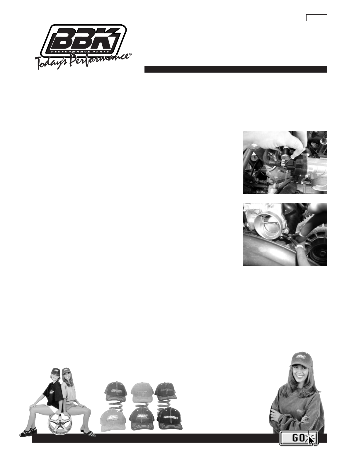
Step 4 (See Photo) Unplug the throttle body electric motor by removing the gray
colored locking clip, and then squeezing the tab on the wiring connector
while pulling it from the motor housing.
Step 5 (See Photo) Using pliers remove the coolant pass through hoses from the
bottom of the throttle body by squeezing the tabs on the hose clamps
together and pulling the hoses away from the throttle body.
NOTE
To prevent the spillage of coolant, we recommend gently clamping vise grip type pliers
onto the hoses before removing.
Step 6 Unbolt and remove the throttle body.
NOTE
Be careful not to damage the throttle body motor housing as you will be re-using it.
Step 7 Using a 4mm socket remove the throttle body mounting studs from the intake manifold.
INSTALLATION INSTRUCTIONS
www.BBKPERFORMANCE.com
IMPORTANT—All appropriate safety equipment (e.i., gloves, tools) must be used during the installation of this product(s).
BBK Performance, Inc. accepts no responsibility for injuries resulting in the installation of any product(s).
Removal Step 4
Removal Step 5
Page 2
Assembly
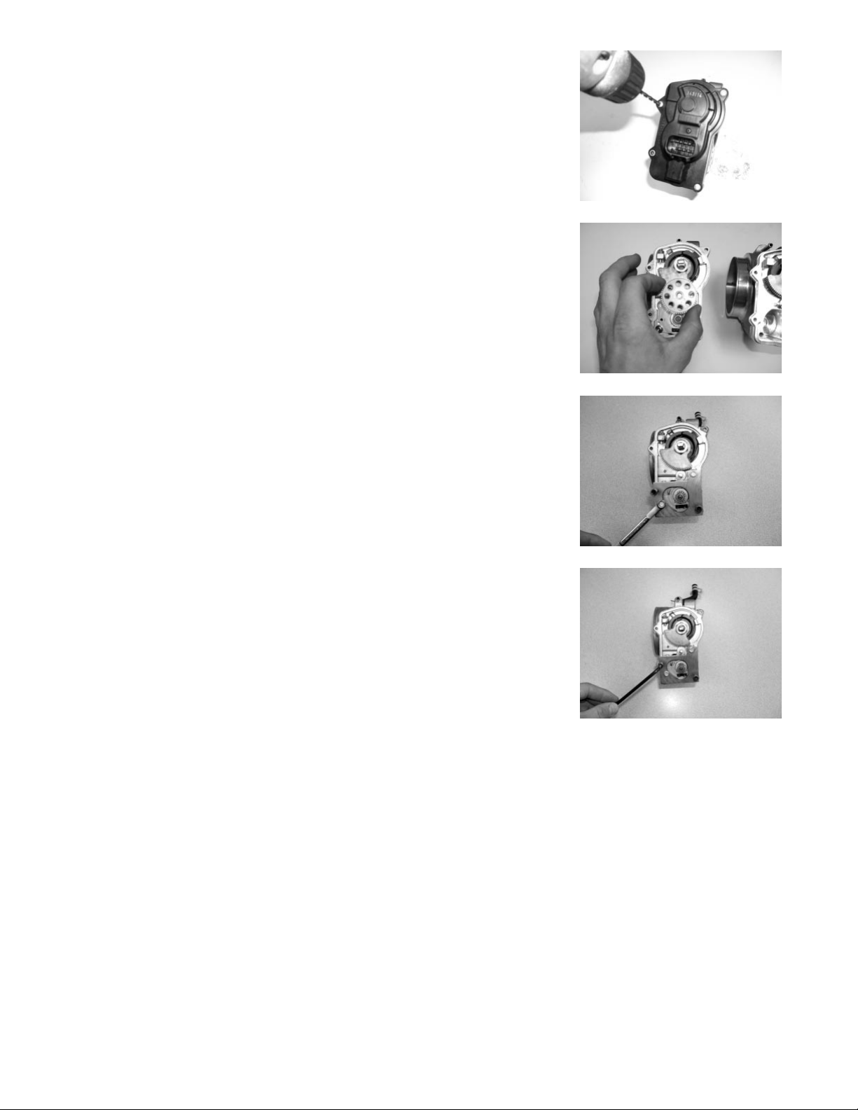
Step 1 (See Photo) Using a drill with a 3/16 bit CAREFULLY drill out the rivets
that attach the throttle body motor housing to the throttle body.
Step 2 Remove the motor housing from the throttle body by gently and evenly
prying the plastic housing up from the throttle body.
Step 3 (See Photo) Remove the round idler gear from the throttle body.
NOTE
Rotation orientation is not critical on assembly.
Step 4 Using a T-25 Torx, unbolt the motor from the throttle body.
Step 5 (See Photos) Using the puller tool remove the motor.
NOTE
To use the puller; lay it flat over the top of the motor. Put the self-tapping
screws through the small puller holes and tighten them with a ºîsocket
into the small holes on top of the motor until the screw heads touch the
puller. Insert the 4mm Allen heads into the threaded holes on the puller
and tighten them evenly against the throttle body. This will pull the
motor straight up and out.
The BBK throttle body is designed to accept the motor with or without
the circular clip
Step 6 Install the motor into the BBK throttle body and tighten the Torx bolts.
Step 7 Install the idler gear onto the BBK throttle body insuring engagement
onto the other gears.
Step 8 8Install the motor housing, be sure to note the electrical contacts.
Be careful not to bend them while sliding the housing into place.
Insert and tighten the supplied Phillips head screws around the housing.
Installation
Step 1 Connect the coolant pass through hoses to the BBK throttle body.
Step 2 Using a 5mm Allen wrench and the supplied bolts, install the throttle
body onto the intake manifold.
Step 3 Plug in the throttle body motor wiring connector, and re-insert the gray
retaining clip.
Step 4 Re-install the intake air inlet hose and attach the coolant hose to the
locating clip.
Step 5 Re-install the decorative intake cover.
Step 6 Connect negative battery cable.
Step 7 Start your engine and let it idle completely uninterrupted for approx. 20 minutes before driving. This will give
the engine management computer time to adapt to the BBK throttle body at normal operating temperatures.
Please visit us at WWW.BBKPERFORMANCE.COM to view a fully photographed installation of this and many other BBK products.
To maximize the performance potential of your GM truck we recommend the following products from BBK PERFORMANCE:
BBK HEADERS
BBK COLD AIR INDUCTION SYSTEM
Assembly Step 1
Assembly Step 3
Assembly Step 5
Assembly Step 5
 Loading...