

Page 1

‘05-'07 5.7 V8 DODGE/CHRYSLER
Magnum / Charger / 300
Cold-Air Induction System
INS-111
Part # 1738
Included in this kit: Inlet pipe, coupler hose, (3) hose clamps, air filter, air filter shield,
locating stud, (1) Phillips head screw, rubber grommet, & rubber trim.
Tools required: Phillips heads screwdriver, 1/4" ratchet, 8mm, and 10mm sockets.
STEP 1
STEP 2
STEP 3
STEP 4
STEP 5
STEP 6
STEP 7
Unplug the Inlet air temperautre (IAT) sensor (located on the inlet tube) by sliding the red colored
locking clip back, and then squeezing the tab on the connector while pulling it from the inlet tube.
Gently pull the PCV tube from the molded nipple on the side of the factory airbox to disconnect it.
Loosen the hose clamp that attaches the inlet hose to the throttle body.
Remove the bolt that attaches the factory air filter box to the core support (behind driver headlight).
Remove the stock intake hose/air box assembly from the vehicle by lifting the air
box straight up and pulling the inlet hose away from the throttle body.
Remove the rubber cup from the bottom of the factory air box. Place the cup back
into its hole in the fender apron.
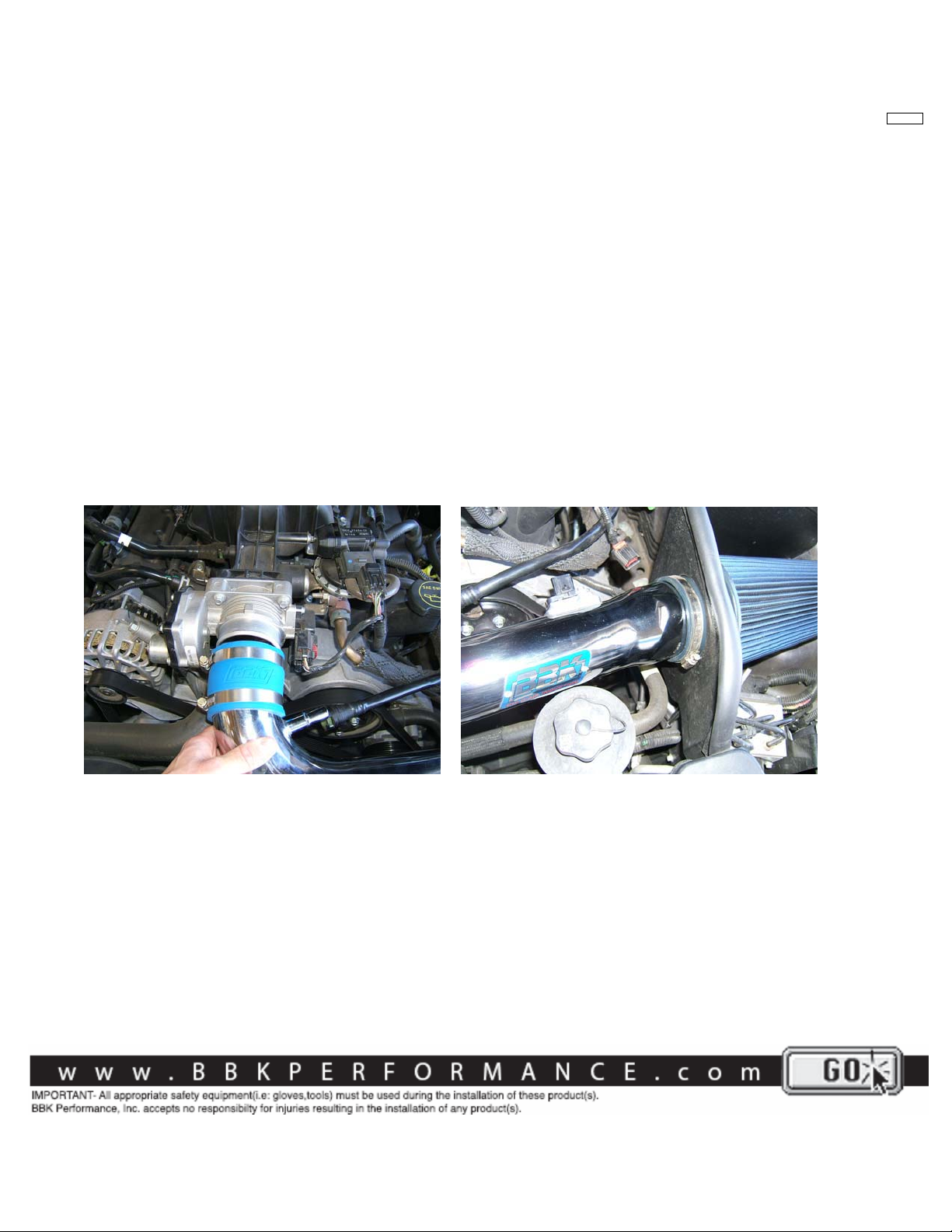
Place the supplied blue coupler hose over the throttle body opening and secure it with one of the
supplied hose clamps. Place another hose clamp over the coupler, but do not tighten it yet.
INSTALLATIONINSTRUCTIONS
STEP 8
STEP 9
NOTE; Steps 8&9 will be performed outside of the vehicle. Install the supplied locating stud into the
small hole in the bottom of the BBK filter shield using the supplied Phillips head screw.The stud will
mount into the rubber cup.
Locate the PCV hole in the supplied filter. This hole will need to line up with the PCV
“pass through” hole in the shield. Place the mouth of the BBK air filter through the
opening in the filter shield and put one of the supplied hose clamps over the end of
the mouth, but do not tighten it yet. Slip the end of the inlet tube into the mouth of
the filter. The mouth of the filter will act as an isolator between the inlet tube
and the filter shield.
Page 2
INS-111
STEP 10
STEP 11
the original mounting hole.
STEP 12
STEP 13
Drop the inlet tube/air filter/shield assembly into place by simultaneously guiding the
stud on the bottom of the shield into the rubber cup, and guiding the inlet tube into
the coupler on the throttle body. NOTE; for this application, the air filter will need
to be rotated and mounted at an angle for proper fitment. The filter should be
high in the back and slope down to the front of the car. When properly
mounted, the “pass through” hole in the shield and the PCV hole in the filter will
line up.
Insert the original air box mounting bolt through the tab on the front of the shield and tighten it into
Tighten the remaining hose clamps over the blue coupler hose and filter.
Push the open end of the PCV hose through the "pass through" hole in the filter shield, then into
the hole in the air filter until at least 1/2” of hose is inside the filter.
STEP 14 Install the IAT sensor by first pushing the supplied rubber grommet into the inlet tube, then
pushing the tip of the sensor into the grommet until the sensor is fully seated in the grommet.
Re-establish wiring connection.
TYPICAL INSTALLATION PHOTOS
Make connection at throttle body. Use air filter mouth as an isolator.
 Loading...