

Page 1

Instruction Manual
Page 2

WARRANTY
Warranty service covers a period of one year from the date of original purchase.
In case of technical failure within one year, repair service will be provided by our
service center or sales outlet free of charge.
We charge customers for repairs after the one-year warranty period has expired.
We charge for repairs regardless of the warranty period if failure resulted from the
user’s negligence, natural disaster or accident.
For more professional repair service, be sure to contact our service center or sales
outlet.
Page 3
Introduction
Thank you for purchasing our product. Electronic measuring instruments
produced by us are high technology products made under strict quality control. We
guarantee their exceptional precision and utmost reliability. For proper use of the
product, please read this operation manual carefully.
Note
l To maintain the full precision and reliability of this product, use it within the
temperature range of 10 °C to 35 °C (50 oF to 95 oF), and within a humidity of
45% to 85%.
l After turning on the power, allow a warm up period of about 30 minutes before
use.
l This equipment should be used with a triple line power cord for safety.
l Due to ongoing product development and improvement, things such as exterior
design and technical specifications can change without prior notice.
l If you have further questions concerning use of this product, visit
www.bkprecision.com.
Safety Summary
Please take a moment to read these operating instructions thoroughly and
completely before operating this instrument. Pay particular attention to WARNINGS
concerning conditions and actions that pose a hazard to the user and CAUTIONS
describing conditions and actions that may damage the instrument.
Before every use, inspect the instrument and other accessories for signs of
l
damage or abnormality.
Keep your body isolated from ground.
l
Never touch exposed wiring, connections or any live circuit conductors.
l
Do not install substitute parts or perform any unauthorized modifications on the
l
instrument.
Use caution when working above 60V DC or 30V AC rms. Such voltages pose
l
a shock hazard.
l Remember that line voltage is present on circuit points such as on-off switches,
fuse, power transformers, etc., even when the equipment is turned off.
l Remember that high voltage may appear at unexpected points in defective
equipment.
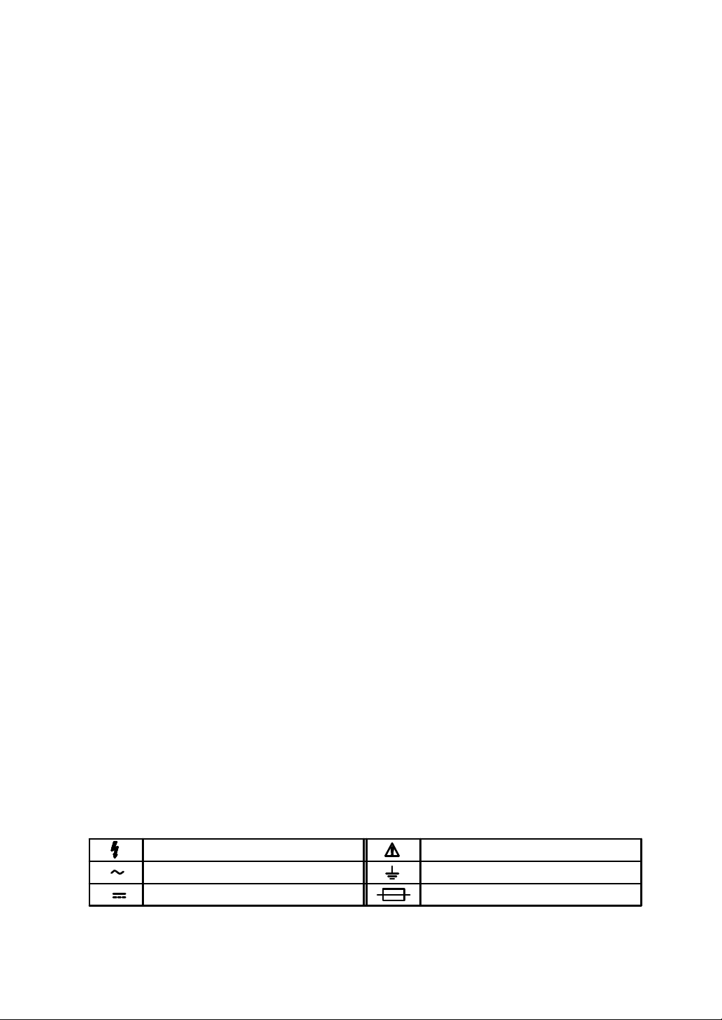
Safety Symbols
DANGEROUS VOLTAGE
AC-ALTERNATING CURRENT
DC-DIRECT CURRENT
SEE EXPLANATION IN MANUAL
GROUND
FUSE
Page 4

CONTENTS
1. PRODUCT DESCRIPTION
1-1. Introduction ----------------------------------------------------- (5)
1-2. Technical Specifications ------------------------------------ (6)
1-3. Equipment Ratings ------------------------------------------- (9)
1-4. Supplied Accessories ---------------------------------------- (10)
2. INSTALLATION
2-1. Initial Inspection ----------------------------------------------- (10)
2-2. Connecting AC Power --------------------------------------- (10)
2-3. Cooling and Ventilation -------------------------------------- (10)
2-4. Position ---------------------------------------------------------- (10)
2-5. Warming-Up --------------------------------------------------- (11)
3. OPERATION
3-1. Controls, Indicators and Connectors --------------------- (11)
3-2. Operating Instructions---------------------------------------- (14)
3-3. Frequency Measurements ---------------------------------- (14)
3-4. Period Measurements --------------------------------------- (16)
3-5. Total Measurements ----------------------------------------- (16)
3-6. RPM Measurements ----------------------------------------- (16)
3-7. Use of RS-232C Serial Interfacing ------------------------ (17)
4. MAINTENANCE
4-1. Fuse Replacement ------------------------------------------- (18)
4-2. Adjustment and Calibration -------------------------------- (18)
4-3. Cleaning and Decontamination ---------------------------- (18)
5. OTHER
5-1. BNC Cable Considerations --------------------------------- (19)
5-2. Attenuator Probes -------------------------------------------- (20)
5-3. Line Frequency Measurements---------------------------- (20)
1. PRODUCT DESCRIPTION
Page 5

1-1. Introduction
This reciprocal FREQUENCY COUNTER is a microprocessor-controlled
instrument for frequency measurement. Due to uniquely developed LSI circuitry in
an expanding/reciprocal system, high accuracy with 9-digit resolution is achieved
with a one second gate time. It covers a frequency range of from 0.1 Hz to 3.5
GHz based on a 10 MHz TCO (Temperature Controlled Oscillator). Other features
include:
l RPM (Revolutions Per Minute) Measuring Function
l External Frequency Standard Input with 9 Digit LED Display
l Attenuator
l Period
l Total
l Low Pass Filter
l Line Filter
Also provided is a self-test function for a quick check of several operating modes.
Each mode can be selected by a front panel push button switch with automatic
decimal points and indicators. The high accuracy, sensitivity and versatility of this
counter make it an extremely valuable instrument to the scientist, engineer,
experimenter and communications technician. Lightweight and compact size make it
practical for use by the hobbyist or field technician.
Page 6
1-2. Technical Specifications
g INPUT A CHARACTERISTICS
h FREQUENCY RANGE: 0.1 Hz to 100 MHz (DC coupled)
30 Hz to 100 MHz (AC coupled)
h SENSITIVITY: 30 mV rms
h COUPLING: AC or DC selectable.
h IMPEDANCE: 1 MΩ resistance shunted by < 40 pF
h ATTENUATOR: x1 or x10 switch selectable
h LOW PASS FILTER: -3 dB point at approx. 100 KHz, switch selectable
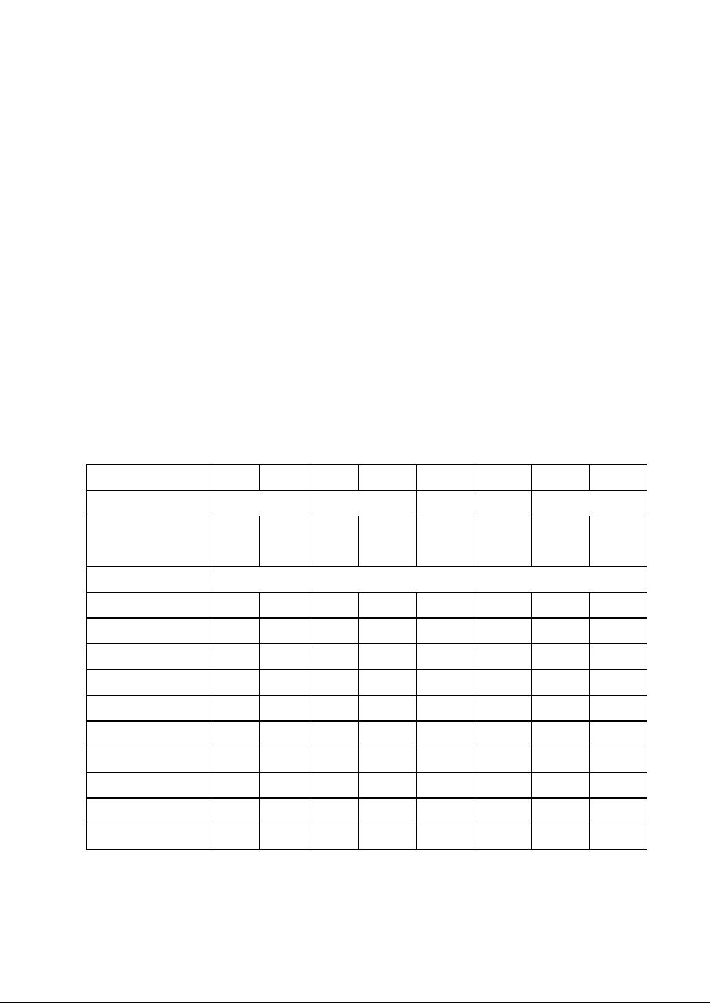
h ACCURACY: ± Time base error ± resolution (Table 1)
h Resolution and Number of Displayed Digits
Time Base Selector INT EXT INT EXT INT EXT INT EXT
Gate Time 0.01S 0.1S 1S 10S
Number of Display
Digits
Frequency (Input A)
0.1 Hz-0.99 Hz 10 uHz 1 uHz 1 uHz 0.1 uHz 0.1 uHz 10nHz 10nHz 1nHz
1 Hz-9.9 Hz 0.1mHz 10 uHz 10 uHz 1 uHz 1 uHz 0.1 uHz 0.1 uHz 10nHz
10 Hz-99 Hz 1 mHZ 0.1mHz 0.1mHz 10 uHz 10 uHz 1 uHz 1 uHz 0.1 uHz
100 Hz-999 Hz 10mHz 1 mHz 1 mHz 0.1mHz 0.1mHz 10 uHz 10 uHz 1 uHz
1 KHz-9.9 KHz 0.1 Hz 10 mHz 10 mHz 1 mHz 1 mHz 0.1 Hz 0.1 mHz 10 uHz
10 KHz-99 KHz 1 Hz 0.1 Hz 0.1 Hz 10 mHz 10 mHz 1 mHz 1 mHZ 0.1mHz
100 KHz-999 KHz 10 Hz 1 Hz 1 Hz 0.1 Hz 0.1 Hz 10 mHz 10 mHz 1 mHZ
1 MHz-9.9 MHz 100 Hz 10 Hz 10 Hz 1 Hz Hz 0.1 Hz 0.1 Hz 10 mHz
10 MHz-99 MHz 1 KHz 100 Hz 100 Hz 10 Hz 10 Hz 1 Hz 1 Hz 0.1 Hz
100MHz 10 KHz 1 KHz 1 KHz 100 Hz 100 Hz 10 Hz 10 Hz 1 Hz
5 6 6 7 7 8 8 9
RESOLUTION
(Table 1)
Page 7
h Max. Input Voltage Level
300
250
200
150
100
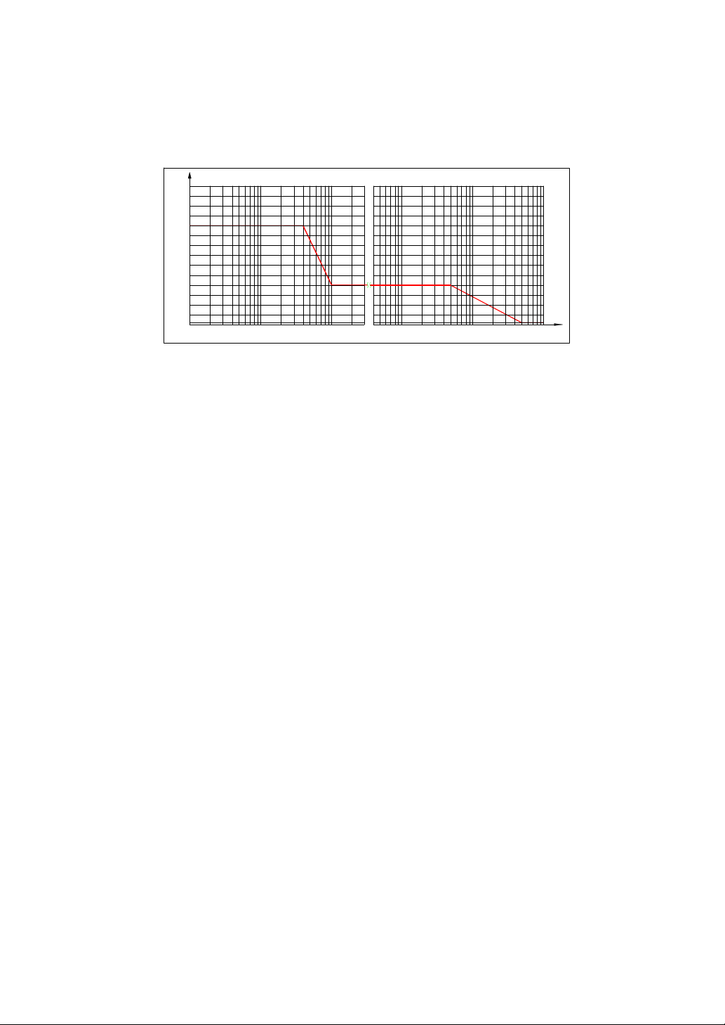
MAX INPUT VOLTAGE (ACV & DCV)
50
25
5
0 100 500
1K 1M 5M 10M 50M 100M
FREQUENCY (Hz)
FIG. 1 MAX. Input Level. (Input A)
h PERIOD RANGE: 10 nS to 10 S
DISPLAY: n/u/m (nano/micro/milli) Sec. with decimal
point
h TOTAL RANGE: 10 Hz to 30 MHz
CAPACITY: 0 to 999 999 999, OVER FLOW : “OF”
h RPM RANGE: 600 to 600 x 106 RPM, OVER FLOW : “OF”
g INPUT C. CHARACTERISTICS
h FREQUENCY RANGE: 80 MHz to 3.5 GHz
h SENSITIVITY: 15mV from 80 MHz to 2000 MHz
20mV from 2000 MHz to 3.0 GHz
30mV from 3.0GHz to 3.2GHz
50mV from 3.2GHz to 3.5GHz
h COUPLING: AC only
h IMPEDANCE: 50 Ω ±5%
h MAX. INPUT LEVEL: 3 V rms sine wave
Page 8
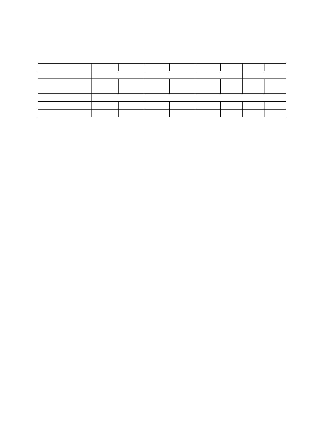
h Resolution and Number of Displayed Digits
Time Base Selector INT EXT INT EXT INT EXT INT EXT
Gate Time 0.01S 0.1S 1S 10S
Number Of
Displayed Digits
Frequency (Input C)
100 MHz-999 MHz 10 KHz 1 KHz 1 KHz 100 Hz 100 Hz 10 Hz 10 Hz 1 Hz
1 GHz-3.7 GHz 100 KHz 10 KHz 10 KHz 1 KHz 1 KHz 100 Hz 100 Hz 10 Hz
5 6 6 7 7 8 8 9
RESOLUTION
(Table 2)
g TIME BASE CHARACTERISTICS
h TYPE: TCO (Temperature Controlled Oscillator)
h FREQUENCY: 10.000000 MHz
h STABILITY: ±1 PPM (±1 count)
h LINE VOLTAGE STABILITY:
Less than ± 1 PPM with ± 10% line voltage variation
h TEMPERATURE STABILITY:
±5 PPM from 0°C to 50°C
h MAX. AGING RATE: ±5 PPM/year
h INT. STD. OUT: 10 MHz (Internal Standard Frequency Output)
LEVEL: 1 V p-p or more. TTL (10TTL)
CAPACITANCE: 15pF
h EXT. STD. IN: 10 MHz (External Standard Frequency Input)
LEVEL: 1.5Vrms to 5Vrms
IMPEDANCE: Approx. 600Ω
g DISPLAY CHARACTERISTICS
h DISPLAY: Nine Digit 0.56" LED with M (Mega) or K (Kilo) Hz; nano, micro,
or milli (n/u/m) Sec.; GT (GATE TIME); H (HOLD); and OF
(OVERFLOW) indicators. FUNCTION and GATE TIME are
user selected. OF display is shown when the count exceeds 999
999 999.
h HOLD: In the FREQUENCY, PERIOD, TOTAL, RPM modes,
measurement in progress is stopped; and the last complete
measurement is displayed. When HOLD is released, a new
measurement begins.
Page 9
h GATE TIME: Depending on input frequency
< 10 mS----------- Somewhere between 0.9 and 9mS
< 0.1 S------------- Somewhere between 9 and 90mS
< 1 S----------------Somewhere between 90 and 900mS
< 10 S---------------Somewhere between 0.9 and 9S
NOTE:
LAST MEASUREMENT DISPLAY WILL REMAIN FOR 10 SECONDS AFTER
SIGNAL OFF.
g DIMENSIONS AND WEIGHT
h Dimensions (WxHxD): 9.4 x 3.5 x 10.6” (240 x 90 x 270mm)
h Weigh (Approx)t: 5.5lbs. (2.5 kg.)
1-3. Equipment Ratings
l Power: 115VAC±10% , 50-60 Hz, 9 W
l Plug and Socket: 3 wire ac power plug and 3 wire outlet
l Fuse: 500 mA/ 250V F type
l Operating Environment:
TEMPERATURE: 0 °C to + 40 °C (Accuracy Specified at 23 °C ± 5 °C)
HUMIDITY: up to 85% RH (Relative Humidity) to 40°C without
temperature extremes causing condensation within the
instrument.
l Storage Environment:
TEMPERATURE: -20°C to +70°C
HUMIDITY: below 85% RH
l Insulation Category II: Portable equipment of local level.
l Pollution Degree: 2
l Protection to IEC 529: Ordinary
Note: Specifications are subject to change without notice.
Page 10
1-4. Supplied Accessories
l User’s Manual --------------------------------------------------------------1
l BNC cable -------------------------------------------------------------------1
l Power cord-------------------------------------------------------------------1
l Spare Fuse-------------------------------------------------------------------1
2. INSTALLATION
2-1. Initial Inspection
This instrument was carefully inspected both mechanically and electrically before
shipment. It should be physically free of damage. To confirm this, the instrument
should be inspected for physical damage which may have occurred in transit. Also,
verify that all supplied accessories have been included.
2-2. Connecting AC Power
This instrument requires 115V AC, 50-60 Hz power through a 3-conductor AC
power cable to be plugged into a three-contact electrical outlet to secure grounding.
If adapted into a 2-conductor cable, use the ground terminal on the rear panel for
grounding the instrument.
CAUTION
THIS INSTRUMENT IS SET TO 115V, AC. BEFORE TURNING ON THE POWER
TO THE INSTRUMENT, MAKE SURE THE VOLTAGE OF THE POWER SOURCE
IS 115V, AC.
2-3. Cooling and Ventilation
No special cooling and ventilation is required. However, the instrument should be
operated where the ambient temperature is maintained.
2-4. Position
This instrument is built as a bench-type instrument with rubber feet and tilt stand
in place. The stand-up angle can be adjusted by changing the angle of the
carrying handle.
Page 11
ON
POWER
OFF
k/u
SEC
RX
RMT
FREQ. A
G.T
PRIOD CATOTAL AARPM 00.1S
0.1S1S10S
mHTX
0.F
M/n
Hz
INPUT C
80MHz 3V MAX. 3.7GHz 100MHz 250V MAX.
INPUT A
1M
FUNCTION
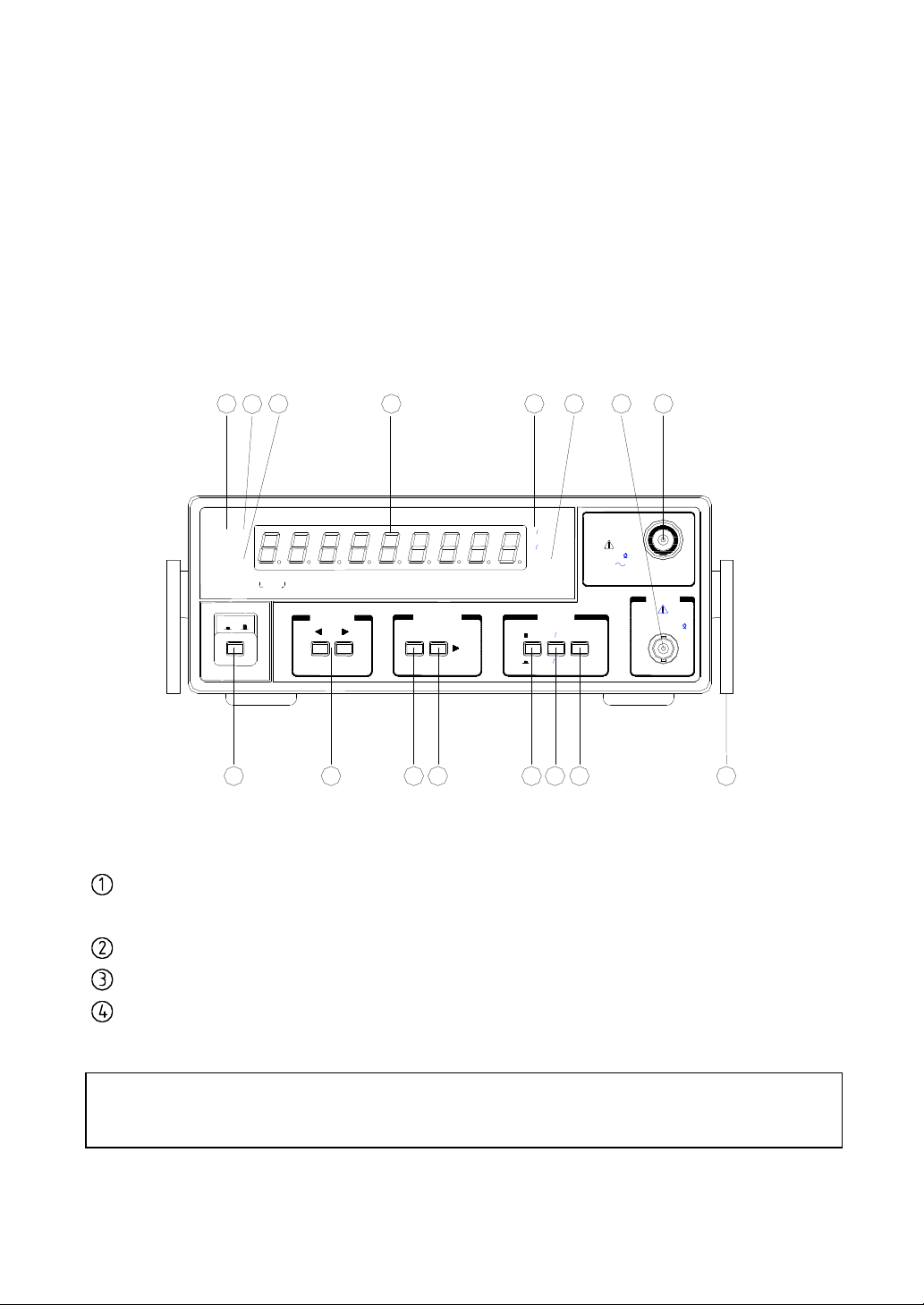
18 15 16 10 12 9 2 3 1 4 5 6 14 8
GATE TIME
MULTIPLIER HOLD TOTAL RESET
OFF LPF
INPUT A
COU
PLE AC ATT 1/1 ON DC 1/10
50
2-5. Warming-Up
Allow at least 30 minutes for the unit to warm up so that it can stabilize.
3. OPERATION
3-1. Controls, Indicators and Connectors
19
20
FIG.2 FRONT PANEL
GATE INDICATOR: The gate light, when lit, indicates the main gate is open
and measurement is in progress.
RS-232C INDICATOR: TX (transmitting), RX (receiving) blinking
OVER FLOW INDICATOR: OF is displayed when there is an overflow.
DISPLAY: 9 digit (0.56“) green LED display used for all readings.
NOTE: LAST MEASUREMENT DISPLAY WILL REMAIN FOR 10 SECONDS
AFTER SIGNAL OFF.
Page 12
UNIT INDICATOR: When lit, indicates that the frequency displayed is in
MHz, KHz, Hz and period is in nano, micro, or milli
(n/u/m) Sec.
HOLD INDICATOR: The HOLD function is engaged the when lit.
INPUT C: Use this input for all frequency measurements above 80
MHz. Female N type connector terminated in 50Ω.
LOW PASS FILTER: With this switch pushed in, the A input is routed through
a low-pass filter with a -3 dB point at approximately 100
KHz. When it is released, the A input is applied directly
to the counter.
ATT. SWITCH: When this switch is set to x10 (pushed in) the A input is
attenuated 10:1 before application to the counter. With
the switch set to x1 (pushed out), the A input signal is
applied unattenuated. The attenuator has no effect on
the C input.
COUPLE. SWITCH: This switch is used to select the input coupling mode,
AC or DC.
INPUT A: Use this input for frequency measurements below 100
MHz and all period measurements. Female BNC
connector. Input impedance is1 MΩ shunted by < 40 pF.
GATE TIME SWITCH: This switch selects the degree of resolution on the
display in all modes except TOTAL.
HOLD SWITCH: In the HOLD function, the display is held but the counter
continues to increment. When HOLD is released, the
display is updated and resumes counting.
FUNCTION SWITCH: This selects the desired operating mode.
a. FREQ. A: When this mode is selected, the counter reads the
frequency of the input at A. Resolution is selected
using the GATE TIME.
b. FREQ. C: When this mode is selected, the counter reads the
frequency of the input at C. All readings are in MHz.
c. PERIOD A: When this mode is selected, the counter reads the
period of the input at A. Resolution is selected using
Page 13
the GATE TIME.
d. TOTAL A: When this mode is selected, the unit counts the cycles of
the signal at input A and continuously displays that count.
e. RPM A: When this mode is selected, the unit displays the RPM
(Revolutions Per Minute) of the signal at input A.
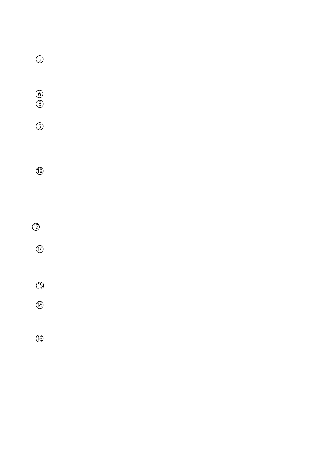
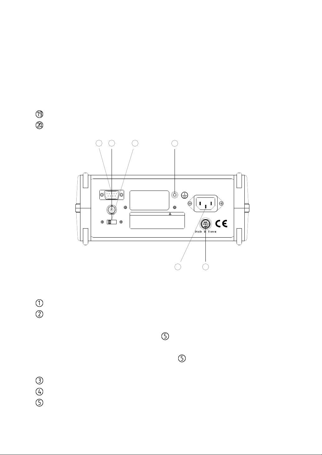
POWER SWITCH: This push type switch, turns on the power when pressed.
TILT STAND: Pull out to adjust tilt.
5
6
2
3
RS-232C
WARNING
TO PREVENT ELECTRIC SHOCK HAZARD AND FIRE,
REPLACE ONLY WITH FUSE OF SAME RATING AND TYPE.
DISCONNECT POWER SUPPLY BEFORE REPLACING FUSE.
INT STD OUT QUALIFIED PERSONNEL.
DO NOT REMOVE COVER. REFER SERVICING TO
EXT STD IN
1
230V~, 50Hz/60Hz
FUSE
4
FIG.3 REAR PANEL
AC INLET: AC power input connector
INT/EXT TIME BASE SELECTOR:
Selects the source of the time base. EXT.STD. IN
sets up BNC as a nominal 600Ω input impedance
path for an external 10 MHz time base signal. INT. STD.
OUT sets up BNC to monitor the internal time base
signal.
GROUND TERMINAL
FUSE HOLDER: Replace fuse by unscrewing
INT/EXT TIME BASE BNC:
Provides a connector through which the internal time
Page 14

base signal can be monitored or through which an
external time base signal can be applied (see item
above). The external signal should have a voltage
range of 1.5 V~5 V rms.
RS-232C CONNECTOR:
Connector for serial interfacing with a computer.
3-2. Operating Instructions
a. Connect the unit up to the AC power.
b. Turn on the unit by pushing in the POWER on-off switch.
c. Set the FUNCTION indicator position to FREQ A and the gate TIME
indicator to the 1 Sec, position.
CAUTION
1. APPLICATION OF INPUT VOLTAGES HIGHER THAN THE LIMITS LISTED IN
THE SPECIFICATIONS SECTION MAY DAMAGE THE COUNTER. BEFORE
APPLYING ANY SIGNAL TO THE INPUTS, MAKE CERTAIN THAT IT DOES NOT
EXCEED THESE SPECIFIED MAXIMUMS.
2. FREQUENCY COUNTER GROUND POINTS ARE CONNECTED DIRECTLY TO
EARTH GROUND. CONNECT GROUND OF THE CIRCUIT UNDER TEST TO
THE FREQUENCY COUNTER GROUND ONLY
3-3. Frequency Measurements
A. INPUT A (0.1 Hz to 100 MHz):
a. Apply the signal to be measured at input A.
b. Set the FUNCTION indicator to FREQ. A
c. Select the resolution using the GATE TIME selector switch.
d. The frequency is indicated on the display. The gate indicator is lit while
the measurement is in progress, and the display is updated at the end of
each measurement interval.
Page 15
e. Engaging the HOLD switch “freezes” the display at the existing reading.
When HOLD is released, the display is updated and resumes counting.
f. Engage the ATTENUATOR if necessary. When set to x10 (pushed in),
the signal at input A is attenuated by a factor of approximately 10 before it
is applied to the counter. This helps prevent miscounting caused by noisy
or improperly terminated high amplitude signals.
g. Engage the LOW PASS FILTER (LPF) if necessary. When this switch is
pushed in, the signal at input A is routed through a low pass filter (-3 dB
point at approximately 100 KHz) before it is applied to the counter. This
helps eliminate counting errors in low frequency measurements by
minimizing effects of high frequency noise that may accompany the signal.
h. When making measurements near the lower cut-off frequency of input A
(10 Hz or less), use DC coupling (Push in the DC COUPLING switch).
B. INPUT C (80 MHz to 3.5 GHz)
CAUTION
THE MAXIMUM INPUT TO THIS INPUT IS 3 Vrms OVER THE INPUT
FREQUENCY RANGE. THE “X 10 ATTENUATOR” DOES NOT APPLY.
a. Apply the signal to be measured at input C.
b. Set the FUNCTION indicator to FREQ. C
c. Select the resolution using the GATE TIME selector switch.
d. The frequency is indicated on the display. The gate indicator is lit while the
measurement is in progress, and the display is updated at the end of each
measurement interval.
e. Engaging the HOLD switch “freezes” the display at the existing reading,
When HOLD is released, the display is updated and resumes counting.
f. The ATTENUATOR, LPF, and COUPLING switches have no effect with
input C.
Page 16
3-4. Period Measurements
a. Apply the signal to be measured at input A.
b. Select the resolution using the GATE TIME selector switch.
c. The period is indicated on the display. The gate indicator is lit while the
measurement is in progress.
d. The ATTENUATOR, LPF, and COUPLING switches operate the same as
they do in the frequency measurements modes.
3-5. Total Measurements
The totalize mode is used to count the total number of events occurring during a
specific time period. The maximum frequency is 30 MHz.
a. With the FUNCTION switch, select the TOTAL A mode. Gate and unit
settings are ignored.
b. Apply the signal to be measured at input A. The accumulated counts will
be displayed continuously to a maximum count of 999999999. If this is
exceeded, the overflow message, OF, will be displayed.
c. The ATTENUATOR, LPF, and COUPLING switches operate the same as
they do in the frequency measurements modes.
NOTE
THE HOLD SWITCH MAY BE USED TO LATCH THE DISPLAY. THE COUNTER,
HOWEVER, WILL CONTINUE TO INCREMENT. WHEN THE HOLD SWITCH IS
RELEASED, THE UPDATED COUNT WILL BE DISPLAYED.
3-6. RPM (Revolutions Per Minute) Measurement
a. Apply the signal to be measured at input A. The count will be
displayed as revolutions per minute (RPM). Maximum count is 999999999.
If this is exceeded, the overflow message, OF, will be displayed.
b. The ATTENUATOR, LPF, and COUPLING switches operate the same as
they do in the frequency measurements modes.
Page 17
3-7. Use of RS-232C Serial Interfacing
1) Hardware/Software Requirements
IBM PC/XT/AT or compatible computer
Microsoft Windows
Serial port for connection with counter
2) Output Data Formats
(1) Baud rate : 9600BPS
1 start bit (0)
8 data bit
1 stop bit (1)
NONE PARITY
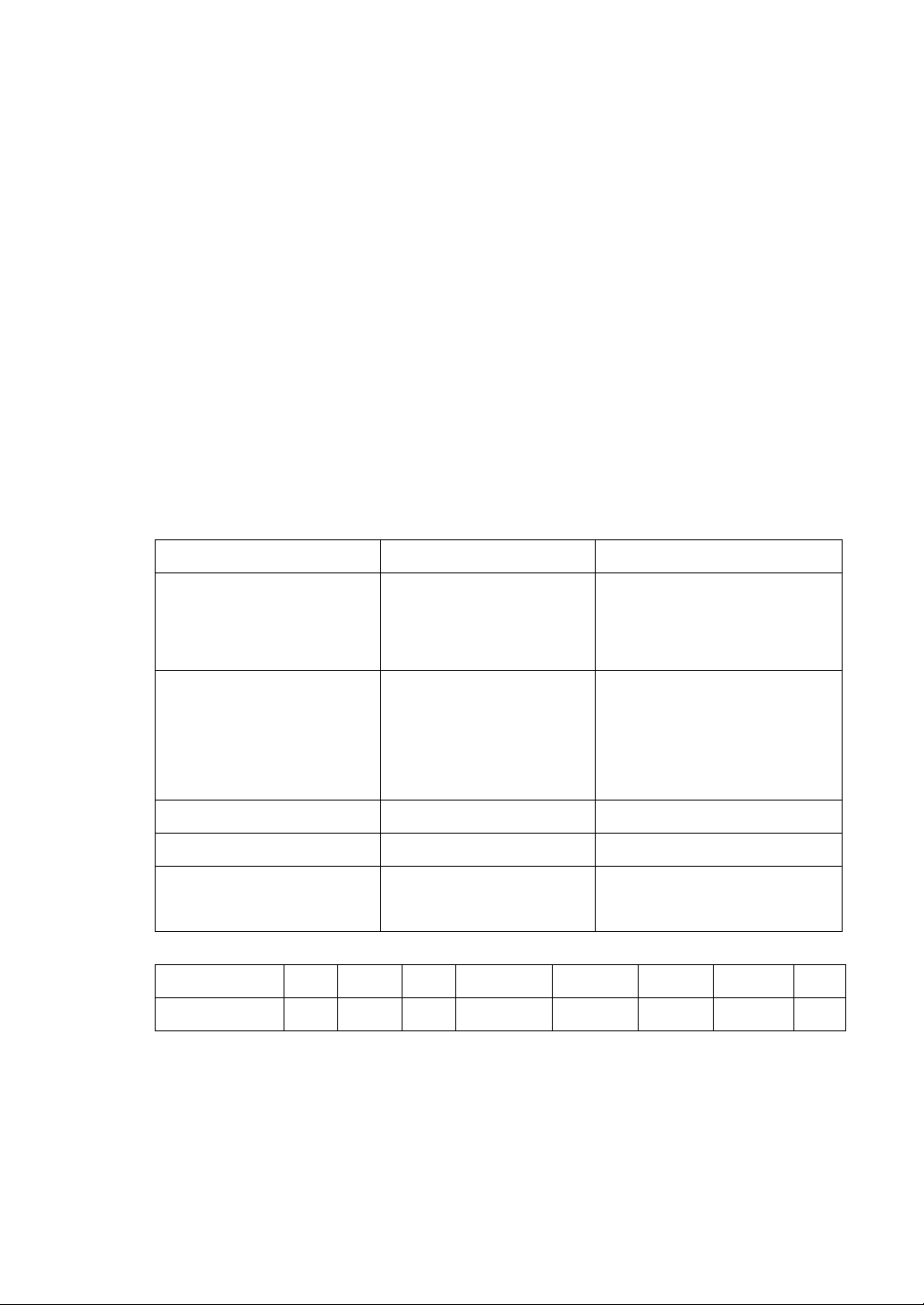
(2) To Frequency counter
Command Parameter Terminate Code
'H' : HOLD '0' : OFF
'1' : ON
CR (0DH)
'2' : TOGGLE
'G' : GATE '0' : 0.01 SEC
'1' : 0.1 SEC
CR (0DH)
'2' : 1 SEC
'3' : 10 SEC
'D' : DATA REQUEST DON'T CARE CR(0DH)
'F' : FUNCTION SET N* CR(0DH)
'R' : REMOTE '0' : OFF
CR(0DH)
'1' : ON
N*= 0 1 2 3 4 5 6 7
3.5GHz,F/C FA NC FC PERIOD TOTAL RPM NC NC
(3) From Frequency counter
DATA UNIT
10BYTES include dp 4bytes CR
Page 18
4. MAINTENANCE
CAUTION
FOR SAFETY, IT IS ESSENTIAL TO PROPERLY MAINTAIN AND SERVICE THIS
INSTRUMENT
WARNING
VOLTAGES WITHIN THIS INSTRUMENT ARE SUFFICIENTLY HIGH TO BE
LETHAL. COVERS MUST NOT BE REMOVED EXCEPT BY PERSONS
QUALIFIED AND AUTHORIZED TO DO SO, AND THESE PERSONS SHOULD
ALWAYS USE EXTREME CARE ONCE THE COVERS HAVE BEEN REMOVED.
4-1. Fuse Replacement
a. Disconnect and remove all connections from any live power source.
b. Unscrew the fuse holder with a screwdriver.
c. Remove the defective fuse.
d. Install a new fuse of the SAME SIZE AND RATING.
e. Screw the fuse holder back in.
CAUTION
REPLACEMENT FUSES MUST HAVE THE SAME SIZE AND RATING AS THOSE
BEING REPLACED.
4-2. Adjustment and Calibration
Regular adjustment and calibration of this instrument is recommended. The
procedures involved should be executed by qualified and authorized personnel only.
4-3. Cleaning and decontamination
The instrument can be cleaned with a soft clean cloth to remove any oil, grease
or grime. Never use liquid solvents or detergents. If the instrument gets wet for any
reason, dry it using low-pressure clean air at less than 25 PSI. Use care and caution
Page 19

around the window cover areas where water could leak into the instrument while
drying.
5. OTHER
5-1. BNC Cable Considerations
The accuracy of radio frequency measurements can be affected by the
connections between the signal source and counter. The main issues involved are
standing waves and cable shunt capacitance.
Waves propagating along a transmission line will be reflected at its ends if the
line is not terminated in its characteristic impedance. These reflections will set up
standing waves in the line, which may cause damage to the signal source or
produce inaccurate measurements. This effect increases as the cable length
reaches one-fourth of the wavelength for the frequency being measured. Standing
waves can be minimized by keeping cable lengths short, or eliminated by providing
a proper termination. RG58 cable, for example, has a characteristic impedance of
50Ω. The proper termination for this cable would, therefore, be a 50Ω resistor
between the center conductor and the shield. A standard BNC, 50Ω cable
termination is most often used for this.
Input A has an input impedance of 1 MO shunted by < 40 pF. Radio frequency
measurements made at this input will experience standing waves and attenuation
due to the shunt capacitance of the cable which adds to the shunt capacitance at
the input. For RF measurements at input A, it is recommended that a 50Ω
termination be used, or that the cable be no longer than three feet (91 cm).
Input C has a built in impedance of 50Ω, thus the need for an external
termination is eliminated.
In situations where a 50Ω termination could affect bias voltages or other DC
voltages in the circuit under test, a blocking capacitor should be used.
Page 20

5-2. Attenuator Probes
When measuring signals at input A that will exceed its maximum input voltage
level (See FIG. 1), a 10:1 attenuating probe such as an oscilloscope probe should
be used.
NOTE
DO NOT USE A 10:1 PROBE WITH THE INPUT C. THESE PROBES ARE
DESIGNED WITH A 10:1 ATTENUATION FOR AN INSTRUMENT WITH AN
INPUT RESISTANCE OF 1 M Ω. THE 50 Ω TERMINATION OF INPUT C WOULD
RESULT IN UNACCEPTABLY HIGH ATTENUATION.
5-3. Line Frequency Measurements
When making line frequency measurements, use of the LOW PASS FILTER, the
ATTENUATOR, and/or the 10:1 probe is recommended.
WARNING
USE CAUTION WHEN MEASURING THE LINE FREQUENCY OF AN AC
OUTLET. USE THE PROBE TIP ONLY, AND MEASURE BOTH SIDES OF THE
LINE. THE NEUTRAL SIDE WILL GIVE A ZERO READING AND THE HOT SIDE
WILL PROVIDE THE DESIRED MEASUREMENT. DO NOT USE THE "GROUND"
LEAD OF THE PROBE. REMEMBER THAT THE CHASSIS OF THE COUNTER
AND THE “GROUND” LEAD OF THE PROBE ARE ALREADY AT EARTH
GROUND (VIA THE 3-WIRE POWER CORD OF THE INSTRUMENT). TOUCHING
THE “GROUND" LEAD TO THE 'HOT" SIDE OF THE LINE WOULD PLACE A
DIRECT SHORT ON THE POWER LINE THROUGH THE PROBE CABLE,
RESULTING IN A BIG SPARK, DAMAGE TO THE PROBE CABLE, AND
POSSIBLE INJURY TO THE USER.
Page 21

Limited One-Year Warranty
B&K Precision Corp. warrants to the original purchaser that its product and the
component parts thereof, will be free from defects in workmanship and materials for
a period of one year from the data of purchase.
B&K Precision Corp. will, without charge, repair or replace, at its’ option, defective
product or component parts. Returned product must be accompanied by proof of
the purchase date in the form a sales receipt.
To obtain warranty coverage in the U.S.A., this product must be registered by
completing and mailing the enclosed warranty card to B&K Precision Corp., 22820
Savi Ranch Parkway, Yorba Linda, CA 92887 within fifteen (15) days from proof of
purchase.
Exclusions: This warranty does not apply in the event of misuse or abuse of the
product or as a result of unauthorized alternations or repairs. It is void if the serial
number is alternated, defaced or removed.
B&K Precision Corp. shall not be liable for any consequential damages, including
without limitation damages resulting from loss of use. Some states do not allow
limitation of incidental or consequential damages, so the above limitation or
exclusion may not apply to you.
This warranty gives you specific rights and you may have other rights, which vary
from state-to-state.
Model Number: ______________ Date Purchased: __________
Page 22

Service Information
Warranty Service: Please return the product in the original packaging with proof of
purchase to the below address. Clearly state in writing the performance problem
and return any leads, connectors and accessories that you are using with the device.
Non-Warranty Service: Return the product in the original packaging to the below
address. Clearly state in writing the performance problem and return any leads,
connectors and accessories that you are using with the device. Customers not on
open account must include payment in the form of a money order or credit card. For
the most current repair charges contact the factory before shipping the product.
Return all merchandise to B&K Precision Corp. with pre-paid shipping. The flatrate repair charge includes return shipping to locations in North America. For
overnight shipments and non-North America shipping fees contact B&K Precision
Corp..
B&K Precision Corp.
22820 Savi Ranch Parkway
Yorba Linda, CA 92887
Phone: 714- 921-9095
Facsimile: 714-921-6422
Email: [email protected]
Include with the instrument your complete return shipping address, contact name,
phone number and description of problem.
Page 23

22820 Savi Ranch Parkway
Printed in Korea
PN: 481-532-9-001
Yorba Linda, CA 92887
USA
TEL: 714-921-9095
 Loading...