

Page 1

Service Manual
(1906 2206)
HDMI
MST719
2009/10/13 - 1 -
Page 2

Contents
1. Precautions and Safety Notices…………………………………………………………3
2. Specification…………………………………………………………………………………5
3. Function Control Description…………………………………………………………….10
4. Circuit Description…………………………………………………………………………11
5. Adjusting Procedure………………………………………………………………………17
6. Trouble Shooting Flow Chart……………………………............................................23
7. Block Diagrams…………………………………………………………………………….26
2009/10/13 - 2 -
Page 3

1. Precautions and Safety Notices
Prior to using this service manual, please ensure that you have carefully followed all the
procedures outlined in the user’s manual for this product.
(1) Read all of these instructions.
(2) Save these instructions.
(3) Follow all warnings and instructions a marked on the product.
(4) Unplug this product from the wall outlet before cleaning. Do not use liquid cleaners or
aerosol cleaners, use a damp cloth for cleaning.
(5) Do not use this product near water.
(6) Do not place this product on an unstable cart, stand or table. The product may fall, causing
serious damage to the product.
(7) Slots and openings in the cabinet and the back or bottom are provided for ventilation, to
ensure reliable operation of the product and to protect it from overheating, those openings
must not be blocked or covered. The openings should never be blocked by placing the
product on a bed, sofa, rug, or other similar surface. This product should not be placed in a
built-in installation less proper ventilation is provided.
(8) These products should be operated from the type of power source indicated on the
marketing label. If you are not sure of the type of power available, consult your dealer or
local power company.
(9) This product is equipped with a 3-wire grounding type plug, a plug having a third (grounding)
pin. This plug will only fit into a grounding-type power outlet. This is a safety feature, if you
are unable to insert the plug into the outlet, contact your electrician to replace your obsolete
outlet. Do not defeat the purpose of the grounding-type plug.
(10) Do not allow anything to rest on the power cord. Do not locate this product where persons
will walk on the cord.
(11) If an extension cord is used with this product, make sure that the total of the ampere
ratings on the product plugged into the extension cord to the waplugged into outlet does not
exceed 15 ampere.
(12) Never push objects of any kind into this product through cabinet slots as they may touch
dangerous voltage points or short out parts that could result in a risk of fire or electric shock.
Never spill liquid of any kind on the product.
(13) Do not attempt to service this product yourself, as opening or removing covers may
expose you to dangerous voltage points or other risks. Refer all servicing to service
personnel.
(14) Unplug this product from the wall outlet and refer servicing to qualified service personnel
under the following conditions:
a. When the power cord or plug is damaged or frayed.
b. If liquid has been spilled into the product.
2009/10/13 - 3 -
Page 4

c. If the product has been exposed to rain or water.
d. If the product does not operate normally, when the operating instructions are followed.
Adjust only those controls that are covered by the operating instructions since improper
adjustment of other controls may result in damage and will often require extension
work by a qualified technician to restore the product to normal operation.
e. If the product has been dropped or the cabinet has been damaged.
f. If the product exhibits a distinct change in performance, indicating a need for service.
2009/10/13 - 4 -
Page 5
2.Specification
Model No.
Display Pixel
Pixel Pitch 0.285mm (H) x0.285mm (V) 0.282mm (H) x0.282mm (V)
Active Display Area 410.4 (H) x 256.5 (V) 473.76 (H) x 296.1(V)
Pixel Type R+G+B vertical stripe R+G+B vertical stripe
Number of Colors 16.2M 16.7M
View Angle
Brightness 300cd/m2 typical 300cd/m2 typical
Contrast Ratio 850:1 typical at CR 10≧ 700:1 typical at CR 10≧
Brightness Uniformity 75% min. 75% min.
Power Source 100-240V~,50/60Hz,50W 100-240V~,50/60Hz,50W
Power Consumption
Sound Output 3W ×2 8Ω 3W ×2 8Ω
±85°degree(H), ±80°degree (V)
<42W Max with speaker
Standby: <1.5W
19”
1440 (H) x 900(V) 1680 (H) x 1050(V)
±85°degree(H), ±80°degree (V)
Typical
<50W Max with speaker
Standby: <1.5W
22”
Typical
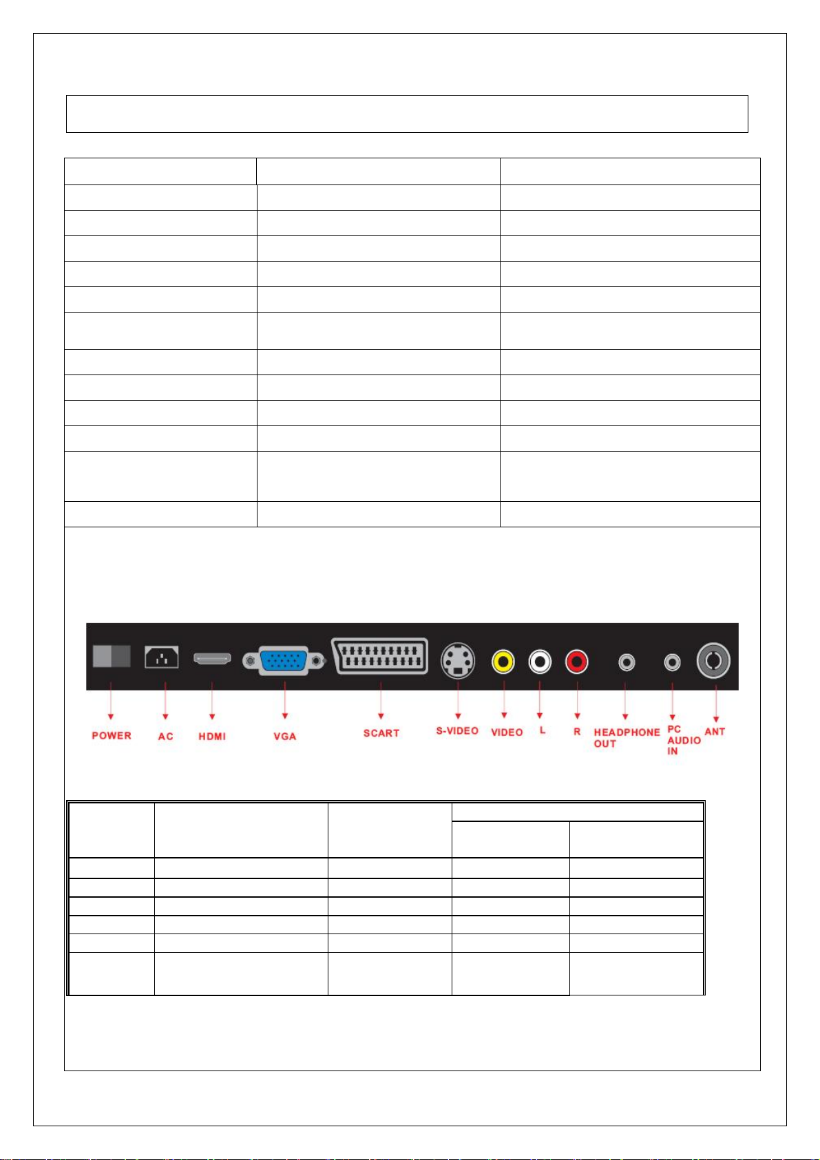
AV/TV Source
Inputs &
Signals Video Format
Outputs
ANT Main-TV
VIDEO Video + L/R Audio CVBS RCA x 1 RCA x 2
S-VIDEO S-VIDEO+ L/R Audio Y/C Mini Din 4 Pin RCA x 2
VGA VGA+ L/R Earphone Analog RGB VGA15 Pin Earphone
HDMI HDMI Digital RGB 19 Pin
SCART
CVBS/RGB ,Video IN/OUT,
Audio IN/OUT
PAL/SECAM
PAL,NTSC,SECA
M
connector
Connector types
Video Sound
PH Type None
SCART
2009/10/13 - 5 -
Page 6
Graphic and Video signal
Output Source
Speaker Out
The Speaker Out Output Jack Shall Consist of
1. 3.5mm Mini-stereo ×1
Analog HD15 PC Signal (RGB)
Format R, G, B Analog
Level/Impedance 0.7Vp-p / 75
DDC 1/2B Compliant with Revision 1.3
Sync H/V separate
3V TTL level / 1k
Frequency
Fh﹦31~80kHz
Fv﹦56~76Hz
Maximum Pixel Clock 135MHz
Connector Mini VGA 15pin (female) ×1
Video (Composite) CVBS Signal
Format PAL,NTSC,SECAM
Level / Impedance 1.0Vp-p / 75
S-Video (Y/C) Signal
Formal Y, C
Level / Impedance Y: 1.0Vp-p / 75
C: ±286mV / 75
RGB PC Timing
STANDARD RESOLUTION V FREQ
Hz
H FREQ
Hz
CLK
MHz
VESA 640×400 85.081 37.861 31.500
VESA 720×400 85.081 37.861 35.500
VGA 640×480 59.941 31.469 25.175
SVGA 800×600 56.250 35.156 36.000
SVGA 800×600 60.317 37.879 40.000
XGA 1024×768 60.004 48.363 65.000
SXGA 1280×1024 60.020 63.981 108.000
Video & S-Video AV Timing
STANDARD RESOLUTION V FREQ
Hz
H FREQ
KHz
CLK
MHz
NTSC 525 60 15.734 12.65
PAL 625 50 15.625 14.50
HDTV/Component A V Timing
STANDARD STANDARD STANDARD STANDARD STANDARD
SDTV 576i SDTV 576i SDTV 576i SDTV 576i SDTV 576i
2009/10/13 - 6 -
Page 7

SDTV 576p SDTV 576p SDTV 576p SDTV 576p SDTV 576p
SDTV 480i SDTV 480i SDTV 480i SDTV 480i SDTV 480i
SDTV 480p SDTV 480p SDTV 480p SDTV 480p SDTV 480p
HDTV 720p HDTV 720p HDTV 720p HDTV 720p HDTV 720p
HDTV 720p HDTV 720p HDTV 720p HDTV 720p HDTV 720p
HDTV 1080i HDTV 1080i HDTV 1080i HDTV 1080i HDTV 1080i
2009/10/13 - 7 -
Page 8
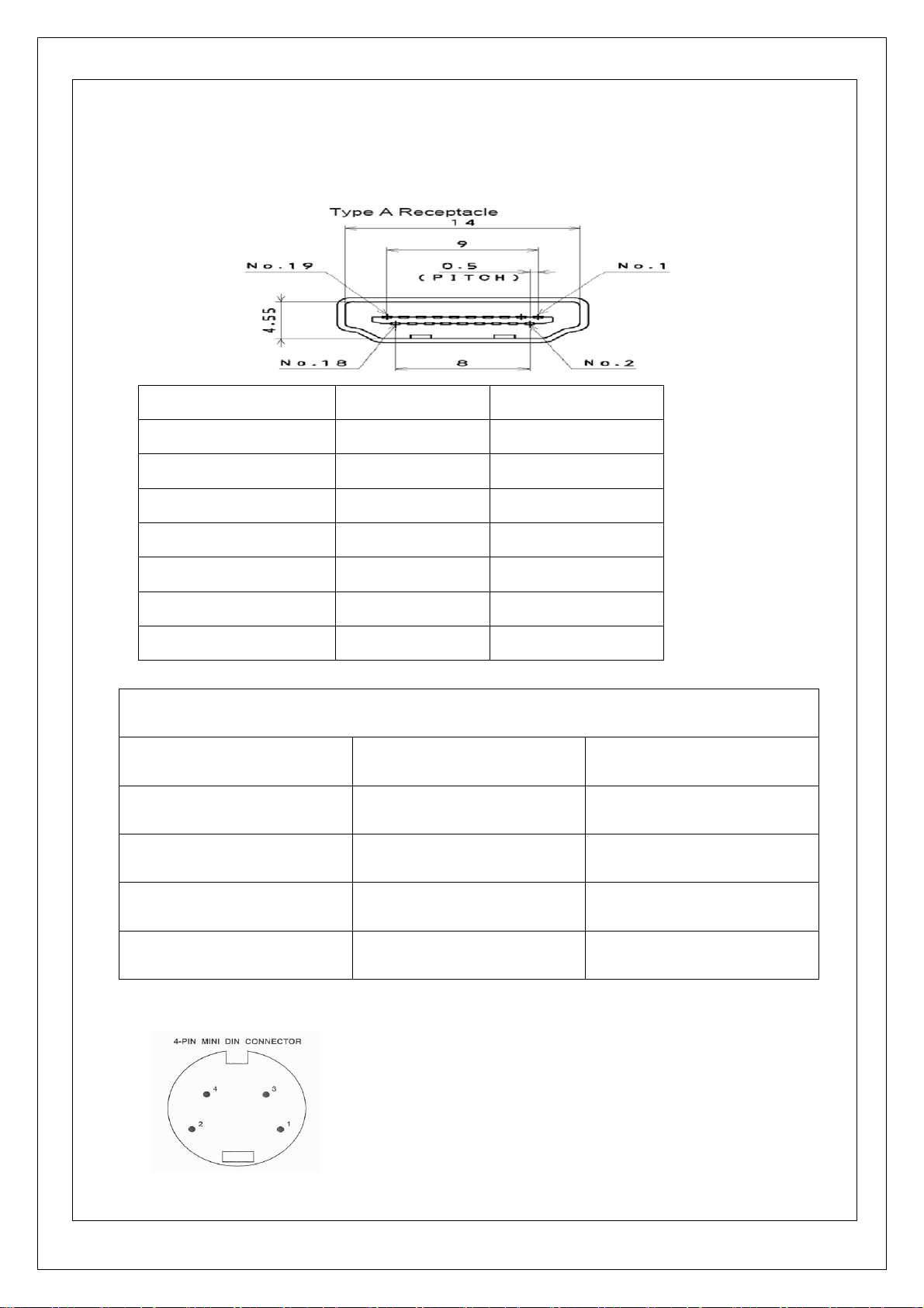
Signal Connector Pin Assignment
HMDI connector is a type A receptacle for video/audio mode.
1.TMDS Data 2+ 9.TMDS Data 0- 17.CEC/GND
2.TMDS Data 2 shield 10.Clock + 18.+5V Power
3.TMDS Data 2- 11.Clock shield 19.Hot Plug Detect
4.TMDS Data 1+ 12.Clock -
5.TMDS Data 1 shield 13.CEC
6.TMDS Data 1- 14.NC
7.TMDS Data 0+ 15.DDC CLK
8.TMDS Data 0 shield 16.DDC Data
VGA connector
VGA connector pin assignment
1.Red 6.GND 11.ISP SDA
2.Green 7.GND 12.VGA SDA
3.Blue 8.GND 13.H-sync.
4.ISP SCL 9.+5V 14.V-sync.
5.GND 10. GND 15.VGA SCL
Mini DIN CNC 4 Pins (SCN570S3NS00000) for S-video, the pin assignment is described as below:
1: Ground
2: Ground
3: Y
4: C
2009/10/13 - 8 -
Page 9
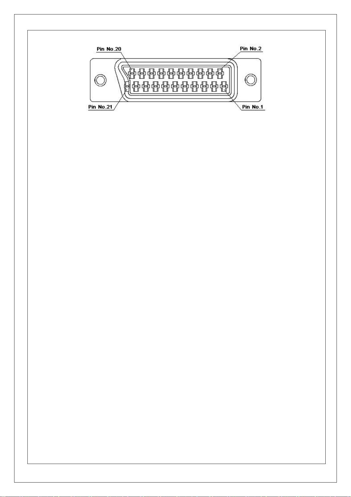
SCART connector
Pin No. Signal Inter Connection Pin No.
1 Audio right channel output (0.5 Vrms, < 1K ohms) 2
2 Audio right channel input (0.5 Vrms, > 10K ohms) 1
3 Audio left channel output (0.5 Vrms, < 1K ohms) 6
4 Audio ground 4
5 Blue signal ground 5
6 Audio left channel input (0.5 Vrms, > 10K ohms) 3
7 Blue signal I/O (0.7 Vp-p, 75 ohms) 7
8 Function switching I/O (L: < 2V, H: > 10V, 10K ohms) 8
9 Green signal ground 9
10 Intercommunication data line No. 1 10
11 Green signal I/O (0.7 Vp-p, 75 ohms) 11
12 Intercommunication data line No. 2 12
13 Red signal ground 13
14 Blanking signal ground 14
15 Red signal I/O (0.7 Vp-p, 75 ohms) 15
16 Blanking signal I/O (L: < 0.4V, H: >1.0V, 75 ohms) 16
17 Composite video signal ground 18
18 Blanking signal ground 17
19 Composite video signal output (1 Vp-p, 75 ohms, sync: negative) 20
20 Composite video signal input (1 Vp-p, 75 ohms, sync: negative) 19
21 Plug shield (common ground) 21
2009/10/13 - 9 -
Page 10
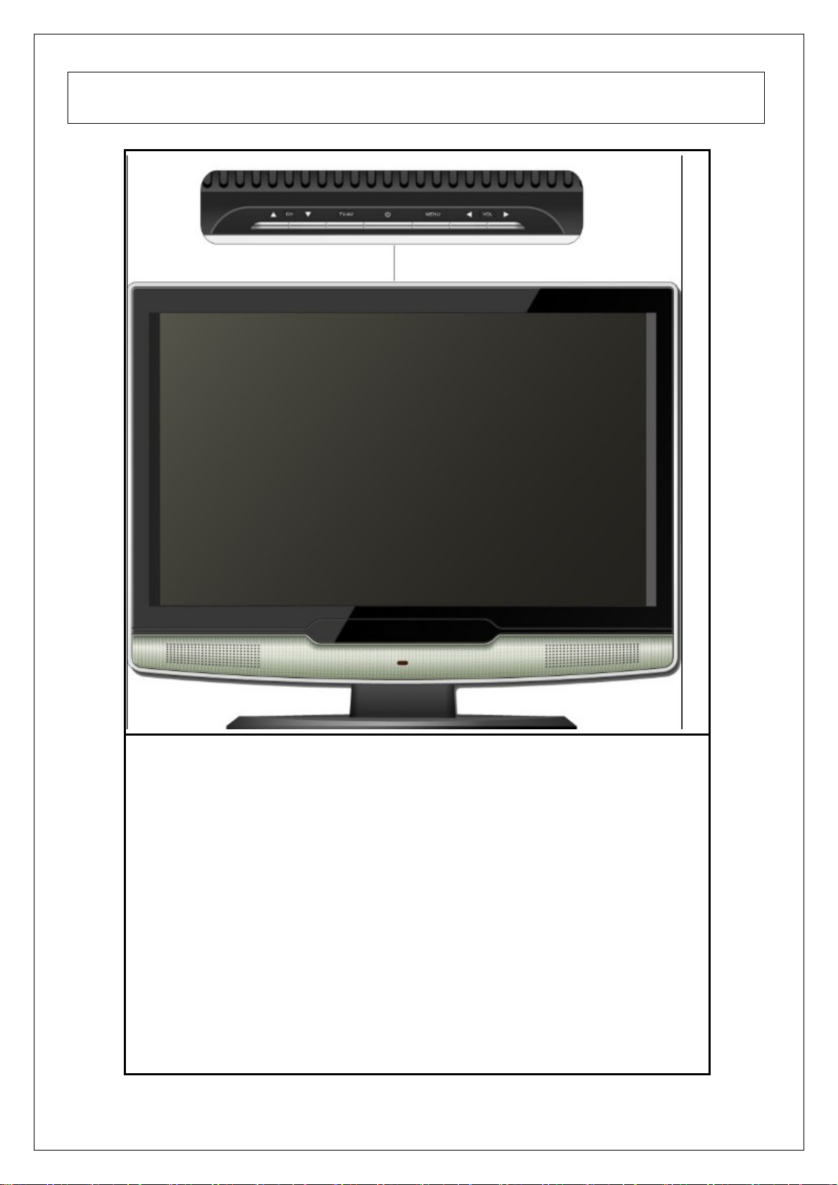
3. Function Control Description
Operation, Adjust and Programming
1.POWER Button
Push this button to turn the unit on, and press it one more time to turn it off.
2.MENU Button
Press this key to pop up the OSD menu under the current selected input mode.
3.TV/AV Button
Press this key to select input sources.
4.CHANNEL (+, - ) Buttons
Press CHANNEL - or + to browse through the TV channels which are not
skipped.
Press CHANNEL - or + as up or down select keys to select the OSD menu item.
5.VOLUME (+ ,-) Buttons
Press VOLUME - or + to adjust the audio volume increase and decrease.
Press VOLUME - or + as right or left select key to select the OSD main menu
item.
2009/10/13 - 10 -
Page 11
4. Circuit Description
(1) SMPS and Voltage Regulator circuit
The LCD TV power board should be designed so that AC power supply AC 100V to 240V and the
input frequency within 50/60Hz can be applied.
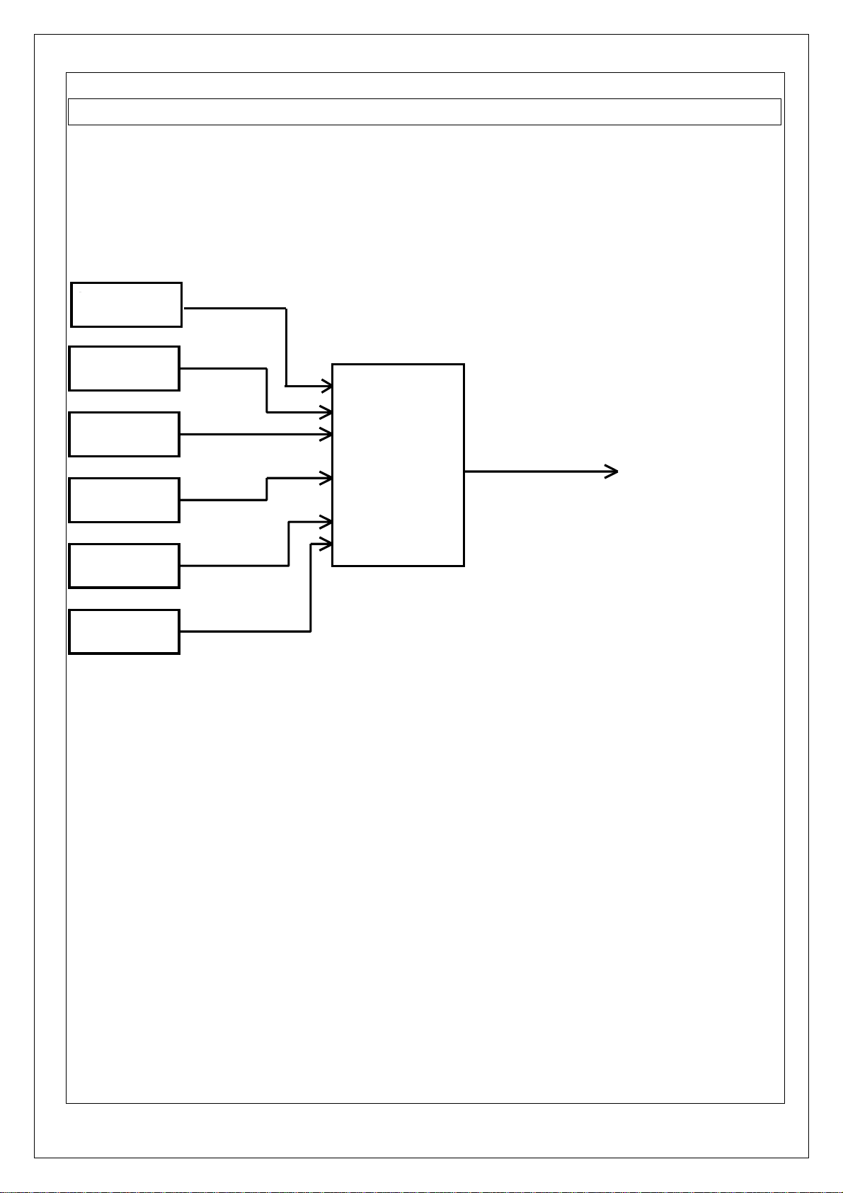
(2) Video Circuit
HDMI
SCART
VGA
MST719
LVDS
TO PANEL
AV
S-VIDEO
ATV
TV
Video Decoder / De-interlace / Scaler MST719
The MST719 is a high performance and fully integrated IC for multi-function LCD monitor/TV
with resolutions up to SXGA(1280x1024)/WXGA+(1440x900). It is configured with an integrated
triple-ADC/PLL, a multi-standard TV video and audio decoder, a video de-interlacer, a scaling engine,
an on-screen display controller, an 8-bit MCU, and a built-in output panel interface. To further reduce
system costs, the MST719 also integrates intelligent power management control capability for
green-mode requirements and spread-spectrum support for EMI management.
2009/10/13 - 11 -
Page 12

(3) Audio Circuit
Multiplexer 4052
DESCRIPTION
The UTC 4052 analog multiplexers is digitally controlled analog switch. The device feature low ON
impedance and very low OFF leakage current. Control of analog signals up to the complete supply
voltage range can be achieved.
FEATURES
*Triple Diode Protection on Control Inputs
*Switch Function is Break Before Make
*Supply Voltage Range=3.0 Vdc to 18 Vdc
*Analog Voltage Range(VDD-VEE)=3.0 to 18V
*Note:VEE must be≤Vss
*Linearized Transfer Characterisstics
*Low-noise-12nV/√Cycle ,f≥1.0kHz Typical
2009/10/13 - 12 -
Page 13

2-channel multiplexer PI5V330
DESCRIPTION
Pericom Semiconductor's PI5V330 is a true bidirectional Quad 2-channel multiplexer/
demultiplexer recommended for both RGB and composite video switching applications. The
switch can bi driven from a current output RAMDAC or voltage output composite video source.
FEATURES
*High-performance solution to switch between video sources
*Wide bandwidth:200MHz
*Low On-Resistance:3Ω
*Ultra-low quiescent power(0.1µA typical)
*Single supply operation:+5.0V
*Fast switching:10ns
*High-current output:100mA
*Packaging(Pb-free & Green Available):
―16-pin 300-mil wide plastic SOIC(S)
―16-pin 150-mil wide plastic SOIC(W)
―16-pin 150-mil wide plastic QSOP(Q)
2009/10/13 - 13 -
Page 14

Stereo D/A Converter CS4334
DESCRIPTION
The CS4334 family members are complete, stereo digital to analog out put systems including
interpolation, 1-bit D/A conversion and out put analog filtering in an 8-pin package. The CS4334
support all major audio data interface formats, and the individual devices differ only in the supported
interface format.
The CS4334 family is based on delta-sigma modulation, where the modulator output controls the
reference voltage input to an ultra-linear analog low-pass filter. This architecture allows for infinite
adjustment of sample rate between 2kHz and 100kHz simply by changing the master clock frequency.
FEATURES
*Complete stereo DAC system: Interpolation D/A, Output analog filtering.
*24bit Conversion.
*96dB dynamic range.
*-88dB THD+N
*Low clock jitter sensitivity.
*Filtered line level outputs
*On-Chip digital de-emphasis
*Popgaurd technology.
2009/10/13 - 14 -
Page 15

Audio Processor MSP3415G
DESCRIPTION
The MSP 34×5G family of single-chip Multistandard Sound Processors covers the sound
Processing of all analog TV standards worldwide, as well as the NICAM digital sound standards. The
full TV sound processing, starting with analog sound IF signal-in, down to processed analog AF-out, is
performed in a single chip. Figure 1-1 shows a simplified functional block diagram of the MSP 34×5G.
FEATURES
* A2-Systems *Japan Stereo
* NICAM-Systems *FM-Satellite Sound
* Very high deviation FM-Mono *FM-Stereo-Radio
* BTSC-Stereo *Standard Selection
* BTSC-Mono + SAP *Automatic Carrier Mute
Block Diagram
2009/10/13 - 15 -
Page 16

Audio Amp. TDA1517
Description
The TDA1517P is an integrated class-B dual output amplifier in a 18-lead dual in-line (DIP18)
plastic medium power package. The device is primarily developed for multi-media applications.
FEATURES
*Requires very few external components
*High output power
*Fixed gain
*Good ripple rejection
*Mute/stand-by switch
*Load dump protection
*AC and DC short-circuit-safe to ground and Vcc
*Thermally protected
*Reverse polarity safe
*Capability to handle high energy on outputs (Vcc=0V)
*No switch-on/switch-off plop
*Protected against electrostatic discharge
2009/10/13 - 16 -
Page 17

5. Adjusting Procedure
A
A
ITEM
Program
Menu
1. M/B Voltage
confirmation
2. Manual
adjustment VGA
Auto adjustment
3. Color Temp.
Adjustment
White-balance
Equipments
Digital
Multimeter
VG828
Pattern
Generator
VG828
Chroma/7110
Requirement
s
Connect with
AC Adapter
Procedure & SPEC
‧ Connect Power to check if Power LED displays the
RED light
‧ Use voltmeter to measure output position, and
check voltage CON1/Pin1-2(12V);
CON25/Pin1-2(5V)
‧ Please refer to appendix A if there is abnormal
phenomenon.
‧ To select the SOURCE then choose VGA.
‧ Press MENU button and use the up/down button to
select the AUTO SYNC of SCREEN menu.(do
twice and confirm the complete action.)
‧ Select SOURCE then choose VGA
‧ Enter the factory area
‧ Select Calibration
calibrate
a. Natural
adjustment
b. Warm
adjustment
c. Cool adjustment Select Cool
4. VIDEO
Select Natural
Enter R.G.B
adjustment
screen
Select Warm
Enter R.G.B
adjustment
screen
Enter R.G.B
adjustment
screen
DVD
Play DVD
‧ Enter Color Temp. to User
‧ Enter User Color temp and adjust the R G B
offset/gain value
‧ Auto adjustment R.G.B value, make the color
temperature of the white screen to
‧
uto adjustment R.G.B value, make the color
temperature of the white screen to
‧
uto adjustment R.G.B number, make the color
temperature of the white screen to
Screen is clear and fluent
adjustment
5.S-VIDEO
adjustment
2009/10/13 - 17 -
Video Cable
DVD
S-Video
Set DVD to
interlaced
output
Play DVD
Set DVD to
Screen is clear and fluent
Page 18

Cable interlaced
output
6. TV
de-interlacing
7. VGA PC
8. VGA TV BOX
9.
PICTURE/VIDEO
Brightness
adjustment
FLUKE
54200
Or other
seem rate of
equipment
PC Mode
VGA Cable
VGA Cable
DVD
S-Video
Cable
Video Cable
Play DVD test
disc VIDEO
ESSENTIAL(
A-1) Play
‧ To send out the TV signal by 54200
‧ To set up the Reduce of OSD to be Strong, and to
reduce snowflakes.
‧ To set up the Reduce of OSD to be OFF, and the
image will display serious snowflakes.
‧ Each Mode can display normally. If there is a
specific Mode that is not appropriate after switch,
press Auto Adjust will to automatically adjust for
appropriate screen.
‧ Confirm PC can automated identify the model of
LCD
‧ Utilize external-connect TV BOX, watching the TV
program; the screen is clear and fluent.
‧ Select the SOURCE to be or AV2
‧ Then press MENU Key to enter the adjustment
mode.
‧ Sending the signal from DVD test disc (second
Contrast
adjustment
or TV Signal
Generator
“FLUKE
54200” or the
same rank
and approved
equipment.
DVD
Set DVD to
interlaced
output Visual
examining
conditions as
follow:
1. Observing
2. Ambient
3. Observing
‧ DVD PLUGE w_Gray Scale
distance
is about
35cm
brightness
is about
‧ Adjust BRIGHTNESS to increase the value.
‧ Then see this line and adjust the default value to
‧ Selects MENU to exit after finishing.
‧ Screen changes evenly. (contrast: turn from min to
150 LUX
angle: 90
paragraph).
be 50.
max).
degree
(measure
from the
central of
2009/10/13 - 18 -
Page 19

the panel
A
A
as 90
degrees)
4. Ambient
temperatu
re: 25±5 C
5. Ambient
humidity:
65±20%
10. Display Mode
Tes t
11.
PICTURE/VIDEO
TINT adjustment
COLOR
adjustment
PC
DVD
S-Video
HDTV
VGA
HDMI
Cable
Video Cable
TV Signal
HDMI Cable
DVD
S-Video
Cable
Video Cable
TV Signal
GENERTOR
FLUKE54200
or the same
rank and
approved
Play DVD test
disc VIDEO
ESSENTIALS
(A-1)
Set DVD to
interlaced
output. Hue
(COLOR)
adjusts from
maximum to
‧ Select the source to be
TV,SCART,Video,S-Video,VGA,HDMI.
‧ Press MENU to select the Screen and Select the
Display Mode to be 16:9, 4:3, Zoom or
Anamorphic.
‧ Make sure the each of Display Mode is normal
work.
‧ Select source then choose VIDEO or S-VIDEO.
‧ Then press MENU Key to enter the adjustment
mode.
‧ Sending the signal from DVD test disc (fifth
paragraph)
equipment.
minimum and
color present
variation
‧ TINT_COLOR
‧
between
black and
white.
‧
djust TINT value to meet the requirement, and
collocate blue attachment slice to see the color
identical from up to down. Default value is 50.
djust COLOR value to meet the requirement and
collocate blue attachment slice to see the color
identical from up and down. Default value is 30 or
25. Select MENU to exit after finishing.
12.
PICTURE/VIDEO
3D COMB FILTER
DVD
S-Video
Cable
Video Cable
Play DVD test
disc VIDEO
‧ Select source then choose VIDEO or S-VIDEO.
‧ Sending the signal from DVD test disc (twelfth
ESSENTIALS
(A-1)
paragraph)
Interlaced
2009/10/13 - 19 -
Page 20

output(NTSC
Mode)
13. WINDOWS.
OVERSCAN(6%)
DVD
S-Video
Cable
Video Cable
‧
‧ Under S-VIDEO MODE, watch the movable circle
‧ Under VIDEO MODE, watch the movable circle
Play DVD test
disc VIDEO
‧ Select source then choose VIDEO or S-VIDEO.
‧ Sending the signal from DVD test disc (eighth
ESSENTIALS
(A-1)
Set DVD to
interlaced
output
pattern is normal without tint. The pattern is normal
under 300 and 400.
patter, static state is normal without the tint, and
movement contains the tint (it is normal
phenomenon). Pattern is normal under 300 and
400, if set DVD to PAL, it will contain tint under
VIDEO MODE.
paragraph)
14. WINDOWS
FREEZE Window
DVD
S-Video
Cable
Video Cable
‧
‧ Watch the screen to check if sees the block screen
Play DVD test
disc VIDEO
‧ Select source then choose VIDEO or S-VIDEO.
‧ Sending the signal from DVD test disc (twelfth
ESSENTIALS
(A-1)
Set DVD to
interlaced
output
‧
‧ Select Freeze Windows function to ON and Check
within SAFE ACTION.
paragraph)
if the screen is pause, then restoring the function to
Default value OFF.
2009/10/13 - 20 -
Page 21

15. NTSC/PAL
DVD
Play DVD test
‧ Select source then choose VIDEO or S-VIDEO.
switch
16. 480p/480i
switch
S-Video
Cable
Video Cable
DVD
Component
Cable
disc VIDEO
‧ Sending the signal from DVD test disc (sixth
ESSENTIALS
(A-1)
Set DVD to
interlaced
output
‧
‧ Switch DVD to output mode NTSC/PAL if there is
Play DVD test
disc VIDEO
‧ Select source then choose VIDEO or S-VIDEO.
‧ Sending the signal from DVD test disc (sixth
ESSENTIALS
(A-1)
Set the DVD
to progressive
paragraph)
the action of switch.
paragraph).
17. Audio
adjustment
a. Volume
Pattern
Generator
Sound input
External
connect
left-right
trumpet(10W/
8Ω)
output
(P-SCAN)
Any Pattern
‧
‧ Switch DVD output mode P-SCN ON/OFF, see if
there is the action of switch mode on the screen.
(480p/480i).
‧ Select source
‧ Then press MENU Key enter AUDIO adjustment
item.
‧ Press < / > Key to Setup the sound volume.
‧ Check if the action is normal.
b. Balance
‧ Press < / > Key to Setup the balance between
left-right trumpet.
‧ Check if the action is normal.
‧ The initial value is located at middle.
i. Sound Mode
2009/10/13 - 21 -
‧ Press < / > Key to setup the surround/off.
Page 22

‧ Check if the action is normal.
18. Setting DPMS Power
regulator
Chroma/6530
VG828
VGA Cable
Signal wire
don connect
with any
signal.
Full White
VGA Input
(800×600/60
Hz)
19. Language
adjustment
20. Defective Cell VG828 Full Red
Full Green
Full Blue
Black
‧ Check OSD if the screen displays count down
picture.
‧ Check if it turns off when the time ends off.
‧ Check if LED show red color.
‧ Check if Power is normal.
‧ AU CMO19” Panel <0.5W
‧ Then press Power ON to check if it can turn on and
LED show blue color.
‧ Check if power is normal.
‧ AU CMO19” Panel <21W
‧ Select required language.
‧ Initial value is set to English or set upon clients’
requirement.
‧ Black pixels:
Section A 2≦
Section B 8≦
‧ RGB: Examination of all the dead pixels in pure
21. Remote
control Function
examination
VGA
Pattern
Generator
TV Signal
Generator
Green and pure Red also pure Blue display.
‧ White pixels
Section A 1≦
Section B 2≦
‧ RGB: Examination of all the dead pixels in pure
Green and pure Red also pure Blue display.
‧ Total: Black Pixels + White Pixels + Sparking Pixels
8≦
‧ Exam all the functions that remote control offered
under all the mode that LCD provides.
DVD or VCD
HDTV Player
HDMI Player
2009/10/13 - 22 -
Page 23

6. Tr ouble Shooting Flow Chart
2009/10/13 - 23 -
Page 24

2009/10/13 - 24 -
Page 25

2009/10/13 - 25 -
Page 26

7. Block Diagram
2009/10/13 - 26 -
Page 27

5
4
3
2
1
INPUT
SCART_CVBS
HDMI_CEC
HDMI_RXCHDMI_RXC+
RX0N
RX0P
RX1N
RX1P
RX2N
RX2P
HOTPLUG
HDMI_SDA
HDMI_SCL
AUMCK
AURCK
AUSCK
AUSD
AV_MODE
FB
PR
PY
PB
S/D_Y
S/D_C
AV_CVBS
CVBS/Y
VGA_R
VGA_G
VGA_B
VGA_VS
VGA_HS
TXD_SDA
RXD_SCL
VSEL
AV_MODE
S/D_Y
S/D_C
SCART_CVBS
AV_CVBS
CVBS/Y
VGA_R
VGA_G
VGA_B
VGA_VS
VGA_HS
TXD_SDA
RXD_SCL
VSEL
RST_34XX
RX0N
RX0P
RX1N
RX1P
RX2N
RX2P
FB
PR
PY
PB
D D
AV_RIN
AV_LIN
PC_RIN
PC_LIN
SCART_VOUT
SCART_RIN
SCART_LIN
INNER_RIN
INNER_LIN
AV_RIN
AV_LIN
SCART_ROUT
SCART_LOUT
PC_RIN
PC_LIN
HDMI_RIN
HDMI_LIN
SCART_VOUT
SCART_RIN
SCART_LIN
INNER_RIN
INNER_LIN
AV_RIN
AV_LIN
SCART_ROUT
SCART_LOUT
PC_RIN
PC_LIN
02_INPUT
HDMI
HDMI_RIN
HDMI_LIN
HDMI_CEC
HDMI_RXC-
HDMI_RXC+
AUDIO
DACM_R
DACM_L
PWD_MT
IF
AF
SDA
SCL
SCART_RIN
SCART_LIN
INNER_RIN
INNER_LIN
SCART_ROUT
SCART_LOUT
AUDIO_MUTE
AMPLIFIER
DACM_R
DACM_L
PWD_MT
AUDIO_MUTE
07_POWERAMPLIFIER
DACM_R
DACM_L
PWD_MT
IF
AF
SDA
SCL
RST_34XX
C C
06_AUDIO
HDMI_RIN
HDMI_LIN
HOTPLUG
HDMI_SDA
HDMI_SCL
AUMCK
AURCK
AUSCK
AUSD
B B
03_HDMI
TUNER
CVBS_OUT
TV_CVBS+
TV_CVBS-
IF
AF
IF
AF
08_TUNER
SCART_VOUT
SDA
SCL
TV_CVBS+
TV_CVBS-
SCART_VOUT
SDA
SCL
AUDIO_MUTE
MST719
AV_MODE
FB
PR
PY
PB
S/D_Y
S/D_C
SCART_CVBS
AV_CVBS
CVBS/Y
VGA_R
VGA_G
VGA_B
VGA_VS
VGA_HS
TXD_SDA
RXD_SCL
VSEL
RST_34XX
HDMI_CEC
HDMI_RXCHDMI_RXC+
RX0N
RX0P
RX1N
RX1P
RX2N
RX2P
HOTPLUG
HDMI_SDA
HDMI_SCL
AUMCK
AURCK
AUSCK
AUSD
CVBS_OUT
TV_CVBS+
TV_CVBS-
SDA
SCL
AUDIO_MUTE
DVDIR_EN
DVD_AUTO
DVD_ON/OFF
PANEL_EN
DVD_STB
DVD_IR
POW_OFF
PHS
PVS
PDE
PCLK
RA[7:0]
GA[7:0]
BA[7:0]
VBL_CTL
BLK_ADJ
DVDIR_EN
DVD_AUTO
DVD_ON/OFF
PANEL_EN
DVD_STB
DVD_IR
POW_OFF
PHS
PVS
PDE
PCLK
RA[7:0]
GA[7:0]
BA[7:0]
VBL_CTL
BLK_ADJ
POWER
09_POWER
PANEL
PHS
PVS
PDE
PCLK
RA[7:0]
GA[7:0]
BA[7:0]
BLK_ON
BLK_ADJ
05_PANEL
DVDIR_EN
DVD_AUTO
DVD_ON/OFF
PANEL_EN
DVD_STB
DVD_IR
POW_OFF
A A
Title
01_TOP
Size Do cument Number Rev
5
4
3
2
Date: Sheet
A3
CV719H_V1.0
CONFIDENTIAL
3000 LongDong Road
19Friday, August 08, 2008
1
Shanghai,China
(86) 021-68791101
of
V1.0
Page 28

5
J20
SCART
SHIELD
21
V_IN
20
V_OUT
19
BLANKGND
18
VGND
17
BLANK
16
R
15
DATAGND
14
RGND
13
DATA
12
G
D D
J24 SVIDEO
C C
J26
AV3-8R4-5
L
R
V
B B
J16
1
2
3
4
5
6
PH-6A
J11
A A
PH-3A
11
CLKOUT
10
GGND
9
SWTCH
8
B
7
A_IN_L
6
BGND
5
AGND
4
A_OUT_L
3
A_IN_R
2
A_OUT_R
1
S_Y
31
S_C
42
7
6
5
D28
6
5
4
3
2
1
D30
D32
1
2
3
4
5
6
12
R157
R165
75
75
3
3
2
2
1
1
AUDIO/RGB/16:9
D29
L13 0
1 2
12
D33
C179
220p/nc
12
R136
75
5
CVBS/C
SCART_VOUT
FB
SCART_R
SCART_G
SCART_B
SCART_LIN
SCART_LOUT
SCART_RIN
SCART_ROUT
C178
220p/nc
C177
220p/nc
C176
220p/nc
12
INNER_LIN
INNER_RIN
12
12
D12
R186 10k
1 2
1 2
1 2
12
L12 0
L11 0
C175
220p/nc
AV_CVBS
12
R192
75
C148 470n
1 2
C155 470n
1 2
C160 470n
1 2
D9
D10
SCART_VOUT
SCART_LIN
SCART_LOUT
SCART_RIN
SCART_ROUT
12
C174
220p/nc
INNER_PY
INNER_PR
INNER_PB
12
12
R183 75
AV_RIN
AV_LIN
AV_CVBS
R188 75
R187 3.3k
12
12
12
C166
220p/nc
R181 75
1 2
12
D19
D20
L10 0
C165
220p/nc
FB
AV_MODE
S/D_Y
S/D_C
16 17
4
12
DB15HD
6
1
11
7
2
12
8
3
13
9
4
14
10
5
15
J27
4
SCART_CVBS
12
75
R182
INNER_PR
SC_R
INNER_PY
SC_G
INNER_PB
SC_B
VGA_5V
3
J15
1
1
PH-6A
D22
2
3
4
5
6
D23
2
3
4
5
6
C167 470n
C168 470n
SCART_CVBS
J23
AV3-8R4-5
L
R
V
SCART_R
6
5
SCART_B
4
3
SCART_G
2
1
12
12
+5Vsb_IN +5V_VSW V_CLAMP
12
R19375
R18975
L8 10R/500mA
1 2
R19075
12
C140
100u/16v
D36
D37
D42
D38
V_CLAMP
12
12
12
12
12
VSEL
L14 10R/500mA
R206 33
PC_R
1 2
RXD
L15 10R/500mA
PC_G
1 2
L16 10R/500mA
PC_B
1 2
R205 33
VGA_SCL
D41
D39
D40
D35
D43
1 2
C169 470n
1 2
1 2
D21
R148 47k
1 2
12
SCART_VOUT
SCART_LOUT
SCART_ROUT
SC_R PR
SC_B
SC_G
12
R15447k
R13247k
11
10
14
13
15
RXD_SCL
12
VGA_SDA
VGA_HS
TXD_SDATXD
12
VGA_VS
3
R155
47k
2
3
5
6
1
R14747k
U16
1B1
1B2
2B1
2B2
3B1
3B2
4B1
4B2
S
OE
R167 0/nc
1 2
R160 0/nc
1 2
R161 0/nc
1 2
12
C138
100n
R13347k
R17147k
PI5V330S
VCC
1A
2A
3A
4A
GND
VGA_HS
VGA_VS
12
C152
10u/25v
R16647k
16
4
7
9
12
8
2
2
1
3
12
PH-2A
2
1
J14
J18
PHONOJACK
TXD_SDA
RXD_SCL
L7 0
1 2
12
C96
220p/nc
GND
1
AUDIO_R
AUDIO_L
8
VCC
7
WP
4
GND
PC_RIN
3
5
4
PC_LIN
2
U18
SCL
SDA
A0
A1
A2
FM24C02
Title
02_INPUT
Size Do cument Number Rev
A3
Date: Sheet
FERRITEBEAD0603
J22
RCA-1
L9
C164
220p/nc
J12
1
1
2
2
3
3
4
4
5
5
6
6
VGA_5V +5Vs b_IN
12
CVBS/C
SCART_RIN
SCART_LIN
1
2
+5V_VSW
12
PH-6A
PR
PY
PB
PB
PY
PR
PY
PB
2
1
D14 BAV70L
VG_R
VG_G
VG_B
12
12
12
R209 75
R210 75
R208 75
VGA_R
VGA_G
VGA_B
C161
100n
2
+5Vsb_IN
TXD_SDA
RXD_SCL
12
C107
220p/nc
VGA_SCL
6
VGA_SDA
5
1
2
3
CV719H_V1.0
1 2
12
R196
R197
4.7k
4.7k
1 2
3
2
1
J17
CVBS/Y
R107
75
PC_RIN
PC_LIN
4.7k
4.7k
R203
R202
1 2
1 2
CONFIDENTIAL
1
PH-3A
3
2
1
1
3000 LongDong Road
Shanghai,China
(86) 021-68791101
29Friday, August 08, 2008
V1.0
of
Page 29

5
4
3
2
1
D27
D26
D D
HDMI_5V
D16
D25 D18
D15
D24
D17
ESD/NC
J25
TMDS_RX2+
CEC
SCL
SDA
PLUG
1
3
4
6
7
9
10
12
13
15
16
19
HDMI_5V
TMDS_RX2-
TMDS_RX1+
TMDS_RX1-
TMDS_RX0+
TMDS_RX0-
TMDS_RXC+
TMDS_RXC-
1 2
R146 100
12
R177
1k
Q27
MMBT3904
1
2 3
18
+5V
2
DATA2 SHIELD
5
DATA1 SHIELD
8
DATA0 SHIELD
11
CLOCK SHIELD
17
GND
20
C C
GND1
21
GND2
22
GND3
23
GND4
14
NC
TMDS DATA2+
TMDS DATA2-
TMDS DATA1+
TMDS DATA1-
TMDS DATA0+
TMDS DATA0-
TMDS CLOCK+
TMDS CLOCK-
HDMI_A
R144 10
R143 10
R142 10
R141 10
R140 10
R139 10
R138 10
R137 10
R178 1k
+5Vsb_IN
12
12
12
12
12
12
12
12
12
HDMI_SCL
HDMI_SDA
12
HDMI_RX2+
HDMI_RX2-
HDMI_RX1+
HDMI_RX1-
HDMI_RX0+
HDMI_RX0-
HDMI_RXC+
HDMI_RXC-
HOTPLUG
R204
RX2P
RX2N
RX1P
RX1N
RX0P
RX0N
HDMI_RXC+
HDMI_RXC-
3
2N7002
Q22
HOTPLUG
+5Vsb_IN+3.3V_stb
12
1
R124
1k
2
1 2
R125 100
HDMI_CEC
4.7k
HDMI_5V
+5Vsb_IN
12
C72
100n
B B
4.7k
C159
100n
4.7k
U17
8
VCC
12
7
WP
4
GND
SCL
SDA
A0
A1
A2
R149
R156
1 2
6
5
1
2
3
1 2
D31
HDMI_SCL
HDMI_SDA
D34
HDMI_SCL
HDMI_SDA
AUSD
AUSCK
AURCK
AUMCK
AUSD
AUSCK
AURCK
AUMCK
U12
1
SDATA
2
SCLK/DEM1
3
LRCK
4
MCLK
CS4334
AOUTL
VA
AGND
AOUTR
8
7
6
5
HDMI_LIN
HDMI_RIN
FM24C02
A A
Title
CONFIDENTIAL
03_HDMI
Size Document Number R e v
A4
5
4
3
Dat e: Sheet
2
CV719H_V1.0
3000 LongDong Road
Shanghai,China
(86) 021-68791101
39Friday, August 08, 2008
of
1
V1.0
Page 30

5
4
3
2
1
VDDP
CRYSTAL
C74
RXCKN
VSYNC1
VGA_B+
VGA_SOG
VGA_G+
VGA_R+
BB+
YY+
SOY
RR+
AVDD_ADC
AV_MODE
C1IN+
Y1IN+
CVBS3P
CVBS2P
CVBS1P
VCOM1
CVBS0P
VCOM0
1 2
1 2
22p
C104
22p
AVDD_DVI
12
X2
12M
1 2
RXCKP
RX0N
RX0P
RX1N
RX1P
RX2N
RX2P
HOTPLUG
R112 390R 1%
HDMI_SDA
HDMI_SCL
HSYNC1
100n
C139
1 2
C137
100n
1 2
C146 100n
1 2
R100
1M
12
R101 1k
VDDP
AVDD_LDVI
AVDD_MPLL
U10
1
2
3
4
5
6
7
8
9
10
11
12
13
14
15
16
17
18
19
20
21
22
23
24
25
26
27
28
29
30
31
32
33
34
35
36
37
38
12
RXCKP
GND1
RX0N
RX0P
AVDD_33
RX1N
RX1P
RX2N
RX2P
HPLUG
REXT
DDCD_DA
DDCD_CK
HSYNC1
VCLAMP
REFP
REFM
BIN1P
SOGIN1
GIN1P
RIN1P
BIN0M
BIN0P
GIN0M
GIN0P
SOGIN0
RIN0M
RIN0P
AVDD_33_1
GND2
HSYNC0
CVBS5P
CVBS4P
CVBS3P
CVBS2P
CVBS1P
VCOM1
CVBS0P
XTAL_IN
128
127
RXCKN
AVDD_MPLL
VCOM039CVBS_OUT40AVDD_33_241GND342SAR043SAR144SAR245VSYNC046VDDP147MCKO48AMUTE49AUWS50AUSCK51AUSD52SPDIFO53PWMD154PWMD255VDDC56SCK57SDI58SDO59CSN60UART1_RX61UART1_TX62GPIO[0]63GPIO[1]
CVBS_OUT
AVDD_ADC
KEYSAR1
KEYSAR0
FB
VDDP
I2S_MCKO
I2S_AUWS
I2S_AUSCK
I2S_AUSD
+1V2
AVDD_LDVI
C109
100n
1 2
12
12
12
C6
C7
C8
100n
100n
22p
C80
100n
1 2
VDDCVDDP VDDP VDDP
C63
C70
100n
100n
1 2
1 2
5V_Keypad
KEY0
KEY1
REMOTE
RED/GRN_LED
DVD_IR
PDE
PCLK
PDE
PCLK
124
126
122
123
120
121
125
119
XIN
DEO
CLKO
XOUT
VDDP4
GPIO[9]
VSYNC1
AVDD_12
MST719
TTL/LVDS/Mini-LVDS
6-bits RSDS
2A/6C/HDMI/CCIR656
3
PVS
PHS
PHS
PVS
118
117
116
GND6
VSYNCO
HSYNCO
R39 4.7k
1 2
115
114
VDDC1
AVDD_LPLL
113
112
VDDP3
111
GPIO[12]
GPIO[11]
1
BA7
108
109
110
GPIO[14]
GPIO[13]
+5Vsb_IN
1 2
2 3
BA6
106
107
GPIO[16]
GPIO[15]
CSN
SDO
SDI
SCK
R36
4.7k
Q11
MMBT3904
VDDC
AVDD_LPLL
VDDP
104
105
GPIO[18]
GPIO[17]
1 2
R89 22k
R73
100
R76100
103
GPIO[20]
GPIO[19]
GPIO[21]
GPIO[22]
GPIO[29]
GPIO[30]
LVB0P
LVB0M
LVB1P
LVB1M
LVB2P
LVB2M
VDDP2
LVBCKP
LVBCKM
LVB3P
LVB3M
LVA0P
LVA0M
PWMD3
PWMD4
GPIO[25]
GPIO[26]
LVA1P
LVA1M
GPIO[27]
GPIO[28]
LVA2P
LVA2M
LVACKP
LVACKM
LVA3P
LVA3M
GND5
RESET
GND4
CS_CEC
64
WP_CTL
7
12
12
SCL
SDA
INT
R59 10k
RN147R
R28 22k
1 2
1 2
VBL_CTL
PANEL_EN
DVD_AUTO
DVD_ON/OFF
DVD_STB
DVDIR_EN
102
101
100
99
98
97
96
95
94
93
92
91
90
89
88
87
86
85
84
83
82
81
80
79
78
77
76
75
74
73
72
71
70
69
68
67
66
65
12
3456
2
18
R29
22k
VDDC
12
R60
0/nc
WP_CTL
RxD_MSCL
TxD_MSDA
+5Vsb_IN
RESET
1 2
1 2
1 2
R65 0
1 2
Q18
MMBT3906
+3.3V_stb
R34 4.7k
R44 4.7k
R33 4.7k
R35 4.7k
R43 4.7k
R46 4.7k
1 2
1 2
1 2
1 2
1 2
1 2
1 2
1 2
BA7
BA6
BA5
BA4
BA3
BA2
BA1
BA0
GA7
GA6
GA5
GA4
GA3
GA2
GA1
GA0
RA7
RA6
RA5
RA4
RA3
RA2
RA1
RA0
SDA
SCL
BLK_ADJ
+5Vsb_IN
U5
Microchip24LC32
8
A0
VCC
7
A1
WP
6
A2
SCL
5
GND4SDA
R71
22k
2
R80
1 2
1
22k
3
R84
33K
1 2
R42 4.7k
R41 4.7k
R45 4.7k
R85 4.7k
R120 4.7k
BA[7:0]
BA[7:0]
GA[7:0]
GA[7:0]
RA[7:0]
RA[7:0]
C42
1
100n
1 2
2
3
R72 0
1 2
1 2
D6
BAV99
12
C46
1u/50v
.
Title
04_MST719
Size Document Number Rev
A2
Date: Sheet
CONFIDENTIAL
CV719H_V1.0
1
3000 LongDong Road
Shanghai,China
(86) 021-68791101
of
49Friday, Augus t 08, 2008
V1.0
VBL_CTL
P_KEY
PANEL_EN
DVD_AUTO
DVD_ON/OFF
DVD_STB
DVDIR_EN
BA5
BA4
BA3
BA2
BA1
BA0
GA7
GA6
VDDP
GA5
GA4
GA3
GA2
GA1
GA0
POW_OFF
RED/GRN_LED
RA7
RA6
RST_34XX
VSEL
RA5
RA4
RA3
RA2
RA1
RA0
RESET
RXD_SCL
TXD_SDA
IR
AUDIO_MUTE
+5Vsb_IN
1 2
R69 4.7k
GPIO0
1 2
TxD_MSDA
R58 33
RxD_MSCL
BLK_ADJ
EEP_WP
R68 10k
Q15
MMBT3904
2 3
R27
510
nRED
Q6
R26
510
Q5
nGRN
1
CS
2
SO
3
WP
GND4SI
U8
WIN25X32
1
+5Vsb_IN
1 2
1
MMBT3904
2 3
+5Vsb_IN
12
1
MMBT3904
2 3
POW_OFF
RST_34XX
VSEL
HDMI_CEC
RXD_SCL
TXD_SDA
AUDIO_MUTE
+3.3V_stb
12
8
VCC
7
HOLD
6
SCK
5
J1
4
4
3
3
2
2
1
1
PH-4A
J2
1
1
2
2
3
3
4
4
5
5
6
6
PH-6A
2
C45
100n
1 2
POWER_KEY
KEY1
KEY0
REMOTE
nGRN
nRED
5V_Keypad
POWER_KEY
PANEL_EN
DVD_AUTO
DVD_ON/OFF
AUDIO_MUTE
VBL_CTL
P_KEY
DVD_STB
POW_OFF
RED/GRN_LED
DVDIR_EN
VSEL
+5Vsb_IN
12
12
R54
R53
4.7k
4.7k
R198 10
靠 俗
1 2
1 2
1 2
1 2
1 2
R176 0
1 2
+3.3V_stb
KEYSAR0
KEYSAR1
IR
R195 470
R199 10
1 2
1 2
R151 10
1 2
1 2
1 2
1 2
1 2
R11510
R17910
R18010
R18410
R17310
1 2
1 2
1 2
R200
1 2
R152 10
R168 0
R170 0
R153 470
R150 10
R169 0
靠 俗
CVBS0P
VCOM0
L5
1 2
10
C111
470p/NC
1 2
C123
470p/NC
1 2
C116
470p/NC
1 2
C106
1 2
470p/NC
10R/500mA
1 2
1 2
1 2
1 2
1 2
C120 220n
1 2
C115 220n
1 2
C110
1 2
C105 220n
1 2
C113 220n
AVDD_DVI
1 2
R111k
R141k
C67
100n
VGA_R
VGA_G
D D
C C
B B
A A
VGA_B
PR
PB
PY
CVBS/Y
S/D_C
S/D_Y
AV_CVBS
SCART_CVBS
TV_CVBS+
TV_CVBS-
靠 俗
5
C143 47n
C142 1n
C131 47n
C129 47n
C171
C172
100p
100p
靠近
C130 47n
1 2
C145 47n
1 2
C147 47n
1 2
C132 47n
1 2
C134 1n
1 2
C144 47n
1 2
C133 47n
1 2
靠近
CVBS2P
C112 220n
C1IN+
Y1IN+
CVBS1P
220n
VCOM1
CVBS3P
靠近
IC
AVDD_ADC
C61
100n
1 2
12
12
1 2
1 2
1 2
1 2
C173
100p
IC
IC
+3.3V_stb
VGA_R+
VGA_SOG
VGA_G+
VGA_B+
R+
R-
B+
B-
SOY
Y+
Y-
C50
100n
1 2
AVDD_LPLL AVDD_MPLL
C108
100n
1 2
+5Vsb_IN
2k
2k
22
4.7k
R22
R12
R13
1 2
1 2
1 2
HDMI_RXCHDMI_RXC+
RX0N
RX0P
RX1N
RX1P
RX2N
RX2P
HOTPLUG
HDMI_SDA
HDMI_SCL
VGA_HS
VGA_VS
AV_MODE
CVBS_OUT
FB
AUMCK
AURCK
AUSCK
AUSD
C86
C75
C94
100n
100n
100n
1 2
1 2
1 2
C77
100n
1 2
12
R16
P_KEY POWER_KEY
12
R1522
12
C2
100u/16v
4
Page 31

5 4 3 2 1
A
+5Vsb_IN
+12V
+5Vsb_IN
R113
+5Vsb_IN
1516
14
13
12
11
10
9
8
7
6
5
4
3
2
1
PDE
10
PHS
9
8
BA6
7
BA4
4.7k
1 2
Q21
MMBT3904
2 3
12
R114
4.7k
R127
Q23
MMBT3904
2 3
4.7k
RXE0-BA2
RXE1-BA0
RXE2-GA6
RXEC-GA4
RXE3-GA2
RXO0-GA0
RXO1-RA6
RXO2-RA4
RXOC-RA2
RXO3-RA0
12
12
INV_ON
INV_ADJ
C128
100n
PH-9A
9
9
8
8
7
7
6
6
5
5
4
4
3
3
2
2
1
1
J13
PHS
PVS
PDE
PCLK
BA7
BA6
BA5
BA4
BA3
BA2
BA1
BA0
BA[7:0]
GA[7:0]
RA[7:0]
GA7
GA6
GA5
GA4
GA3
GA2
GA1
GA0
RA7
RA6
RA5
RA4
RA3
RA2
RA1
RA0
PANEL_POWER
HS
VS
DE
CLK
FH12_50S
J6
1
P1
2
P2
3
P3
4
P4
5
P5
6
P6
7
P7
8
P8
9
P9
10
P10
11
P11
12
P12
13
P13
14
P14
15
P15
16
P16
17
P17
18
P18
19
P19
20
P20
21
P21
22
P22
23
P23
24
P24
25
P25
26
P26
27
P27
28
P28
29
P29
30
P30
31
P31
32
P32
33
P33
34
P34
35
P35
36
P36
37
P37
38
P38
39
P39
40
P40
41
P41
42
P42
43
P43
44
P44
45
P45
46
P46
47
P47
48
P48
49
P49
50
P50
D
R126
BLK_ON
1 2
C
BLK_ADJ
RXE0+ BA3
RXE1+ BA1
RXE2+ GA7
RXEC+ GA5
RXE3+ GA3
RXO0+ GA1
B
RXO1+ RA7
RXO2+ RA5
RXOC+ RA3
RXO3+ RA1
PANEL_POWER
1 2
17
18
19
20
21
22
23
24
25
26
27
28
29
30
PCLK
PVS
BA7
BA5
1
4.7k
R134
1
10k
J8
J7
1
2
3
4
5 6
A
Title
CONFIDENTIAL
05_PANEL
Size Document Number R e v
A4
Dat e: Sheet
CV719H_V1.0
3000 LongDong Road
Shanghai,China
(86) 021-68791101
59Friday, August 08, 2008
of
V1.0
Page 32

5
A
C99 1u/10v
C97 1u/10v
C1001u/10v
C98 1u/10v
12
12
12
AUDIO_SEL1
AUDIO_SEL0
C54 1u/10v
C56 1u/10v
C55 1u/10v
C53 1u/10v
1 2
1 2
1 2
1 2
1 2
1 2
1 2
1 2
+5V_SW
R77
4.7k
1 2
D D
PC_LIN
SCART_LIN
INNER_LIN
HDMI_LIN
PC_RIN
SCART_RIN
INNER_RIN
HDMI_RIN
R110 100k
R111 100k
R207 100k
R90 100k
R201 100k
12
12
12
12
12
R83 100k
R82 100k
R97 100k
C C
12
12
12
R92 47k
R96 47k
+5V_SW
1 2
R78
4.7k
R94 47k
R99 47k
12
12
12
12
R98 47k
R93 47k
R91 47k
R95 47k
4
+8V_LDO
R55
47k
1 2
12
12
C64 100n
1 2
1
5
2
4
12
14
15
11
9
10
6
33K
R56
10u/25v
C28
U11
0Y
1Y
2Y
3Y
0X
1X
2X
3X
B
A
INH
VEE7VSS
CD4052B
VDD
16
3
Y
13
X
8
12
1 2
100n
C57
AUDIO_L
AUDIO_R
RST_34XX
AUDIO_L
AUDIO_R
+5VD_34XX
AV_LIN
AV_RIN
1 2
IF
AF
R104 100k
R105 100k
R106 100k
R81 1k
R63
4.7k
3
U7
MSP34x5G_PMQFP44
C69 56p
1 2
C73
100p
12
12
12
12
C92 330n
C89 330n
C90 330n
C87 330n
C88 330n
+5VD_34XX
R79 1k
SCL
SDA
1 2
C65 56p
1 2
1 2
1 2
1 2
1 2
1 2
1 2
1 2
X1
18.432M
C60
22p
12
2
ANA_IN1+
3
ANA_IN-
43
MONO_IN
40
SC1_IN_L
41
AUDIOL
AUDIOR L_OUT
SC1_IN_R
37
SC2_IN_L
38
SC2_IN_R
11
STANDBYQ
10
ADR_SEL
12
I2C_SCL
13
I2C_SDA
18
ADR_CL
21
I2S_DA_IN2
14
I2S_CL
17
I2S_DA_IN1
15
I2S_WS
16
I2S_DA_OUT
22
RESETQ
5
XTAL_IN
6
XTAL_OUT
C51
22p
1 2
2
D_CTR_OUT0
D_CTR_OUT1
NC2
NC023NC124NC3
28
32
DVSUP
AVSUP
AHVSUP
DACM_L
DACM_R
SC1_OUT_L
SC1_OUT_R
CAPL_M
AGNDC
VREFTOP
AHVSS
AVSS
DVSS
TESTEN
VREF1
VREF2
ASG
1
+5VD_34XX
+5VA_34XX
+8V_LDO
19
1
33
DACML
27
DACMR
26
C117 1.5n
C118 1.5n
1 2
1 2
31
R_OUT
30
+8V_LDO
AUDIO_SEL0
9
AUDIO_SEL1
8
7
TP
34
36
42
35
44
20
4
29
25
39
12
12
1 2
C103 100u/16v
C91 10n
C76 10u/25V
12
C102 3.3u/50V
C93 100n
1 2
DACM_L
DACM_R
L_OUT
R_OUT
B B
+5V_SW
+5VD_34XX +5VA_34XX
12
C81100n
1 2
+5V_SW
C4010n
C41100n
1 2
+8V_LDO
C8210n
12
C62100n
C6810n
12
1 2
PWD_MT
PWD_MT
C71 100u/16V
+
+
C52 100u/16V
C170
220p
R174
1 2
1k
R162
1 2
1k
1
1
1 2
2 3
2 3
1 2
1 2
C154
220p
1 2
Q26
MMBT3904
Q24
MMBT3904
R158 1k
R194 1k
SCART_LOUT
SCART_ROUT
Title
06_AUDIO
Size Do cument Number Rev
Date: Sheet
CV719H_V1.0
A3
CONFIDENTIAL
3000 LongDong Road
Shanghai,China
(86) 021-68791101
69Friday, August 08, 2008
V1.0
of
A
Page 33

5
4
3
2
1
+12V_SW
R21 100k
C4 100u/16v
MMBT3906
12
D2
R32 10k
12
Q9
21
1N4148
2
R23 10k
1
3
PWD_MT
1
2
BAV70L
PWD_MT
D D
+6V
C156100n
C149
100u/16V
+
12
R128 33K
1 2
U15A
84
3
+
2
-
R135 27K
1 2
C141 100p
OP_VCC
1
POL4558
R159
1 2
33K
R118 100
DACM_L
C C
1 2
C124 1u/10V
12
C121 18n
R119 13K
R130 10k
C126
1n
C135
100n
+12V_SW
R129
100
1 2
+
C158 10u/16V/nc
C114
220u/16V
C162
+
100u/16V
R191 33
AUDIO_MUTE
PHONE_LIN
12
D13
OP_VCC
Q28
1
MMBT3904
2 3
Q25
1
MMBT3904
2 3
DACM_R
R116 100
1 2
C125 1u/10V
12
C122 18n
R117 13K
C127
1n
R131 10k
U15B
84
5
+
12
7
6
-
POL4558
R145 27K
1 2
C157 10u/16V/nc
C163
+
100u/16V
C150 100p
R164 33
PHONE_RIN
12
D11
PWD_MT
1 2
R175 1k
R163 1k
1 2
+12V_SW
12
12
D3
1 2
3
R384.7k
PWD_MT
PHONE_LIN
PHONE_RIN
12
R37
4.7k
MUTE
12
R40
0
Q12
1
MMBT3904
2 3
+12V_SW +12V_AMP
1 2
VCC
OUT1
OUT2
HGND1019HGND11
5
20
L1 31R/3A
7
4
6
B B
C1
J19
GND
1
Audio_R
3
AMP_RIN
5
AMP_LIN
4
PHONE_LIN
2
Audio_L
PHONOJACK
A A
5
R172 0/nc
R185 0/nc
12
12
4
AMP_LIN
AMP_RINPHONE_RIN
R51 10k
R2 10k
12
12
R50
16k
1 2
0-2V STANDBY
3.3V-6.4V MUTE
8.5V-18V POWERON
R1
16k
1 2
C14
10u/25v
1u/10v
1 2
MUTE
12
3
1 2
C18
1u/10v
12
C16
100u/16v
U1
1
INV1
INV2
M/SB
SVRR
TPA1517P
9
8
3
SGND2HGND110HGND211HGND312HGND413HGND514HGND615HGND716HGND817HGND918PGND
C10 470u/16v
1 2
1 2
C11 470u/16v
2
12
C9
470u/16v
C12
100n
1 2
AUDIO_L+
AUDIO_R+
4
3
2
1
TJC3-4A
4
3
2
1
J9
Title
07_POWERAMPLIFIER
Size Do cument Number Rev
CV719H_V1.0
A3
CONFIDENTIAL
Date: Sheet
1
3000 LongDong Road
Shanghai,China
(86) 021-68791101
of
79Friday, August 08, 2008
V1.0
Page 34

5
4
3
2
1
SCL
+12V_SW
SDA
TV_CVBS
AF
12
C25
100u/16v_nc
U13FQ1216ME
SCL
SDA
D D
+5V_TUNER_RF
4
SCL
5
SDA
6
AS
AF_AUDIO
IF_AUDIO
CVBS
12
14
11
TV_CVBS
AF
IF
+5V_TUNER_RF
+5V_TUNER_RF
L3
3
12
C136
220u/16v
C151
100n
12
10n/NC
C153
12
C C
P5VRF
GND115GND216GND317GND418NC11NC22NC37NC48NC59NC6
P5VIF
13
12
12
C31
100n
10
C32
10n/NC
12
C30
220u/16v
FB0805
12
12
C21
100u/16v
1
2
3
4
5
6
7
8
9
10
11
12
13
14
J10
1
2
3
4
5
6
7
8
9
10
11
12
13
14
PH-14A/NC
+5V_TUNER_RF
R103 470k
L4 0
1 2
C38
220p/nc
R66 10
1 2
12
R61
75
1 2
1 2
R62 0
C101
1 2
220n
C95
1 2
220n
TV_CVBS+TV_CVBS
TV_CVBS-
TV_CVBS+
TV_CVBS-
CVBS_OUT
TV_CVBS
R75 0/nc
R74 0
12
21
D7
1N4148
C78
1 2
12
470n
B B
TP4
1
12
TEST POINT
1
C20
100n
U3
VIN
GND
2
78M05
LM340
VOUT
TAB
4
+5V_TUNER_RF
3
1
TP3
TEST POINT
+12V_SW
D4
2 1
1N4001
12
100u/16v
C24
12
C22
100n
C27
+8V_LDO
3
12
78M08
U2
LM340
1
VIN
VOUT
GND
TAB
2
4
100u/16v
12
R108
1
R123
120
680
12
Q19
MMBT3904
2 3
12
R109
100
R122120
1 2
+5V_TUNER_RF
2
1
12
12
Q20
MMBT3906
3
1 2
R121
SCART_VOUT
68
C11910p/nc
A A
5
4
3
Title
CONFIDENTIAL
08_TUNER
Size Document Number R e v
A4
Dat e: Sheet
2
CV719H_V1.0
3000 LongDong Road
Shanghai,China
(86) 021-68791101
89Tuesday, August 26, 2008
of
1
V1.0
Page 35

5
C58 100n
+12V_IN
12
C44
470u/16v
DC3AIN
1
2
+12V
1 2
FS1 20N-060H/L
J21
3
D D
1 2
12
C48
120p
1 2
1 2
R87
100k
C47
1n
8
SYNC
7
EN
6
COMP
5
FB
MP1423
VSW
GND
PAD
4
+12V_IN
U9
BS
VIN
C84 10n
1
1 2
2
3
4
12
C83
100n
C85
470p/nc
R102
10/nc
9
1 2
1 2
L6 47uH/3A
D8
SK34B
2 1
R86 10k 1%
1 2
1 2
R88
31K 1%
12
C39
470u/16v
3
+5Vsb_IN
12
C29
100n
1
TP6
TEST POINT
2
+5Vsb_IN
R24
47k
1
R19
1 2
0/NC
+5V_DVD
Q8
AO3401
2
12
C13
10u/25v
1 2
3
1
+5Vsb_IN
1
C79
100n
Q17
AO3401
12
1
1
+5V_DVD+12V_IN
C15
470u/16v
TP8
TEST POINT
3
A4
AHOLE138
1
3
12
C5
100n
1
TP2
TEST POINT
A2
AHOLE138
1
A3
AHOLE138
1
DVD_CTRL
PANEL_EN
DVD_IR
DVDIR_EN
DVD_ON/OFF
DVD_AUTO
TP1
TEST POINT
1
R25
10k
1 2
DVD_CTRL
R8
4.7k
DVD_STB
DVD_STB
C C
+5Vsb_IN +3.3V_stb
1 2
CM1084
U6
CM1084
3
VIN
GND
1
B B
A A
POW_OFF
1 2
VOUT
TAB
R3
4.7k
Q4
MMBT3904
2
4
1
C49
220u/16v
1
2 3
12
+12V_IN
R4
10k
1 2
Q2
MMBT3904
2 3
C23 100n
1 2
12
R47
100k
C19
120p
C17
1 2
1n
1 2
TP7
1
TEST POINT
C66
100n
1 2
+12V_IN +12V_SW
R17
47k
R20
2.2k
12
R18
4.7k
1
8
SYNC
7
EN
6
COMP
5
FB
+3.3V_stb
1 2
1 2
Q7
MMBT3904
2 3
VSW
GND
PAD
MP1423
U4
BS
VIN
12
C36 10n
1
1 2
2
3
4
9
3
C3
10u/25v
C37
12
470p/nc
C34
100n
R67
10/nc
BM1117-ADJ
U14
BM1117-ADJ
VIN
2
VOUT
4
TAB
ADJ
1
+5Vsb_IN +5V_SW
R70
47k
1 2
R64
2.2k
1 2
1 2
2
Q1
AO3401
C43
12
10u/25v
2 1
L2 47uH/3A
D5
SK34B
R48 10k 1%
1 2
+1V2
C59
100u/16v
3
1
12
1 2
R49
31K 1%
12
2
A1
AHOLE138
1 2
POW_OFF_INV
5
1
Q16
MMBT3904
2 3
4
R7
4.7k
1 2
TP10
TEST POINT
R31
4.7k
1
R5
12
2.2k
1
Q10
MMBT3904
2
1 2
Q3
MMBT3904
2 3
D1
1
2
+5Vsb_IN
1 2
1
2 3
+12V_IN
TP9
TEST POINT
1
BAW56L
3
10k
R30
+5V_DVD +12V_IN
J4
1
1
2
2
3
3
4
4
5
5
6
J3
1
2
3
4
5
PH-5A
PANEL_POWER
3
C35
100n
1
6
PH-6A
12
99Friday, August 08, 2008
1
1
3000 LongDong Road
Shanghai,China
(86) 021-68791101
+5Vsb_IN
R10 1 0k
1 2
R9 0/ nc
12
PANEL_POWER_IN
1
+3.3V_stb
+5Vsb_IN
Title
Size Do cument Number Rev
Date: Sheet
1 2
R57 47k
1 2
R52 2.2k
1 2
Q13
MMBT3904
2 3
PANEL_POWER_IN
3
2
1
J5
09_POWER
A3
R6 0
12
6
5
4
12
CV719H_V1.0
2
C33
10u/25v
C26
100u/16v
1
2
3
4
5
Q14
AO3401
CONFIDENTIAL
TP5
TEST POINT
of
V1.0
 Loading...