

Page 1
SUBJECT:
( )
( )
DK1594-TP0
Service Manual
MODEL NO:
DK1594-TP0
( )
DOC.NO:
( )
EFFECTIVE DATE:
( )
REVISION: A1
( )
PAGE 1 OF 34
REVISION STATUS
( )
PAGE
1
2
3
4
5
6
7
8
9
10
11
12
13
14
15
16
17
18
19
20
21
…
33
34
REV.
A1
A1
A1
A1
A1
A1
A1
A1
A1
A1
A1
A1
A1
A1
A1
A1
A1
A1
A1
A1
A1
A1
A1
A1
COPY TO All CONTENTS
APPROVED BY/
( )
CONCURRED BY/
REVIEWED BY/
PREPARED BY/
1
Page 2

TABLE OF CONTENTS
1. Precautions and Safety Notices ································· 1
2. Specification ················································· 2
3. Front Panel Function Control Description ························· 8
4. Adjusting Procedure ········································· 13
5. Trouble Shooting Flow Chart ·································· 16
6. Exploded Diagram and Spare Parts List ·························· 19
7. Block Diagram ·············································20
8. Schematic Diagram ·············································21
9. PCB Layout Diagrams ·········································31
0
Page 3

1. Precautions and Safety Notices
Prior to using this service manual,please ensure that you have carefully followed all the procedures outlined in
the user's manual for this product.
(1) Read all of these instructions.
(2) Save these instructions.
(3) Follow all warnings and instructions a marked on the product.
(4) Unplug this product from the wall outlet before cleaning.Do not use liquid cleaners or aerosol cleaners, use
a damp cloth for cleaning.
(5) Do not use this product near water.
(6) Do not place this product on an unstable cart,stand or tablle.The product may fall,causing serious
damage to the product.
(7) Do not tear up the EMI label, if the label has been destroyed,that must to past same size label on the same
position.
(8) Slots and openings in the cabinet and the back or bottom are provided for ventilation,to ensure reliable
operation of the product and to protect it from overheating,those openings must not be blocked or
covered.The openings should never be blocked by placing the product on a bed,sofa, rug, or other similar
surface.This product should not be placed in a built-in installation less proper ventilation is provided.
(9) This products should be operated from the type of power source indicated on the marketin label. If you are
not sure of the type of power available, consult your dealer or local power company
(10) This product is equipped with a 3-wire grounding type plug,a plug having a third (grounding) pin. This
plug will only fit into a grounding-type power outlet. This is a safety feature, if you are unable to insert the
plug into the outlet, contact your electrician to replace your obsolete outlet. Do not defeat the purpose of
the grounding-type plug.
(11) Pay attention to the code which connects with apheliotropism board of inside panel.and don’t hook it.
(12) Do not allow anything to rest on the power cord.Do not locate this product where persons will walk on the
cord.
(13) If an extension cord is used with this product,make sure that the total of the ampere ratings on the
product plugged into the extension cord to the waplugged into outlet does not exceed 15 ampere.
(14) Never push objects of any kind into this product through cabinet slots as they may touch dangerous
voltage points or short out parts that could result in a risk of fire or electric shock.Never spill liquid of any
kind on the product.
(15) Do not attempt to service this product yourself,as opening or removing covers may expose you to
dangerous voltage points or other risks.Refer all servicing to service personnel.
(16) Unplug this product from the wall outlet and refer servicing to qualified service personnel under the
following conditions :
a.
When the power cord or plug is damaged or frayed.
b.
If liquid has been spilled into the product.
c.
If the product has been exposed to rain or water.
d.
If the product does not operate normally,when the operating instructions are followed.Adjust only those
controls that are covered by the operating instructions since improper adjustment of other controls may
result in damage and will often require extension work by a qualified technician to restore the product to
normal operation.
e.
If the product has been dropped or the cabinet has been damaged.
f.
If the product exhibits a distinct change in performance,indicating a need for service.
1
Page 4
2. Specification
15” panel specification:
Item Specifications
Display pixels
1024 (H) x768 (V) pixels ( 1 pixel = 1 RGB cells )
Active Area 304.128mm (H) x 228.096mm (V)
Pixel Pitch 0.297mm (H) x 0.297mm (V)
Display Colors 16.2M
Pixel Arrangement R+G+B vertical stripe
Display Mode Normally white
Brightness 250 cd/m2 typical
Contrast Ratio 400:1 typical
Brightness Uniformity 75% min.
Viewing Angle
120°(H) 100°(V) at CR ≧ 10
Color Chromaticity (CIE) White: x = 0.313 , y = 0.329 typical
Frame Rate
Response Time
Surface Treatment
60Hz
16ms typical
Hard Coating(3H),Anti-glare(Haze 25)
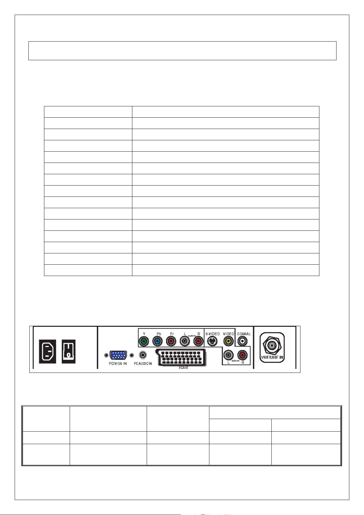
INPUT Source :
Signals Video Format
Outputs
Main-TV Analog TV PAL/SECAM PH Type TV (CABLE/AIR)
VIDEO Video + L/R Audio CVBS RCAx1+ RCAx2
(Red, White)
2
Connector types Inputs &
OSD
VIDEO1 (REAR)
Page 5
S-VIDEO S-VIDEO+ L/R Audio Y/C Mini Din 4 Pin VIDEO2 (S-VIDEO)
SCART RGB+Y/C+
CVBS(input/output)+
SCART 21pin VIDEO3(SCART IN)
L/R(input/output)
YPbPr
Component
(Y, Pb/Cb, Pr/Cr)
480i, 576i, 480p,
576p, 720p, 1080i
RCAx3+RCAx2
(Red, White)
VIDEO4 (YPbPr)
+ L/R Audio
PC/VGA
AC IN/Power
Switch
Note:
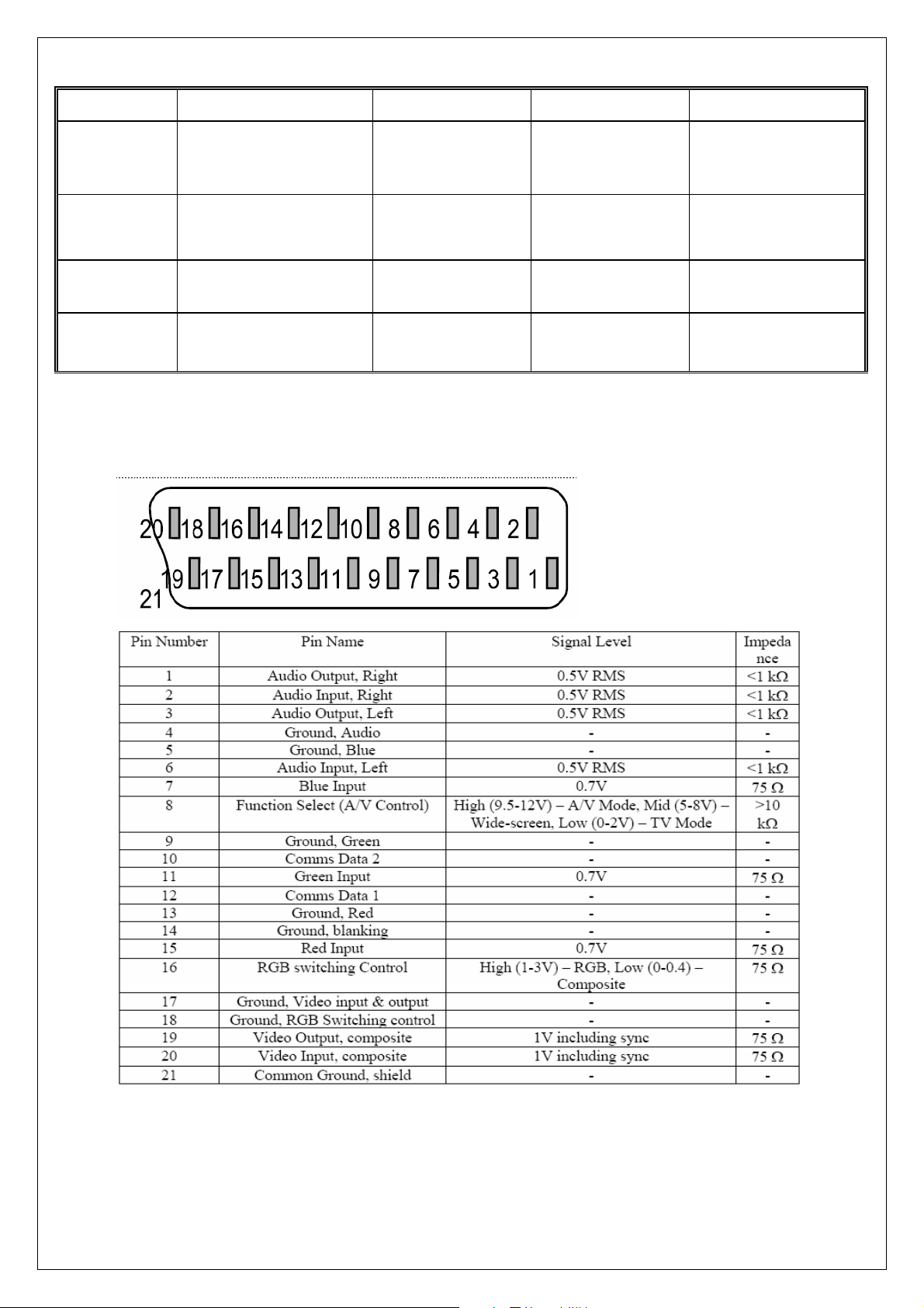
A. SCART connector.
VGA IN+ PC AUDIO
Analog RGB VGA 15 Pin
VIDEO5(VGA IN)
IN
AC Power IN AC 100~240V YC14 AC IN
B. VGA Connector.
3
Page 6
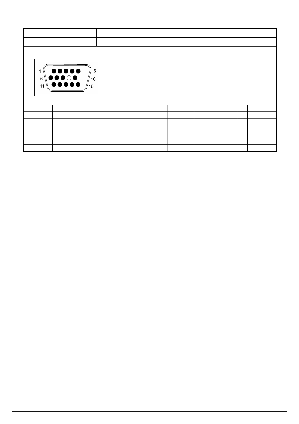
VGA type connector pin assignment
1.Red Video 6.Red Ground 11.ISP-SEL-I
2.Green Video 7.Green Ground 12.SDA
3.Blue Video 8.Blue Ground 13.H-sync.
4.None 9.+5V 14.V-sync.
5.GND 10.Sync GND 15.SCL
C.RCA jacks are all female type.
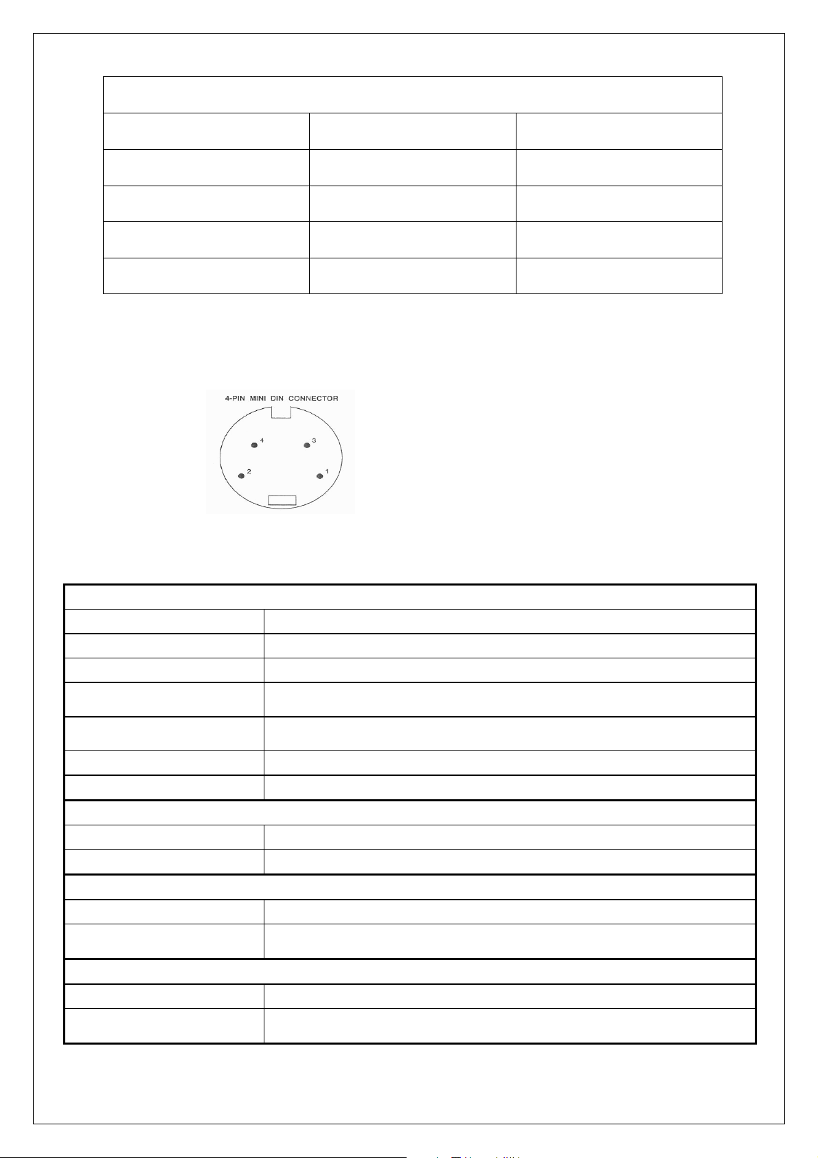
D.Mini DIN CNC 4 Pins (SCN570S3NS00000) for S-video, the pin assignment is
described as below:
1: Ground
2: Ground
3: Y
4: C
VGA
Format
Level/Impedance
DDC 1/2B
Sync H/V separate
Frequency Fh = 31~80 kHz
Maximum Pixel Clock
Connector
Format
Level / Impedance
Format
Level / Impedance Y: 1.0Vp-p / 75Ω
Format
Level / Impedance Y: 1.0Vp-p / 75Ω
4
R, G, B Analog
0.7Vp-p / 75Ω
Compliant with Revision 1.0
3V TTL level / 1kΩ
Fv = 56~76 Hz
135 Mhz
Mini VGA 15 pin (female) x 1
Video (Composite) CVBS Signal
NTSC, 4.43NTSC, PAL_M, PAL(B,G,H,D,N), SECAM
1.0Vp-p / 75Ω
S-Video (Y/C) Signal
Y, C
C: ± 286 mV/ 75Ω
Analog HD15 Video Signal (YPbPr/YCbCr)
Y, Pb, Pr or Y, Cb, Cr
Pb/Cb, Pr/Cr: 0.7 ± 0.035Vp-p / 75Ω
Page 7
HDMI Timing
STANDARD RESOLUTION
V FREQ
Hz
H FREQ
kHz
CLK
MHz
480p 720x480 60 31.46 27
576p 720x576 50 31.25 27
720p 1280x720 50 37.5 74.25
720p 1280x720 60 45.0 74.25
1080i 1920x1080 50 28.12 74.25
1080i 1920x1080 60 33.75 74.25
VGA Timing
STANDARD RESOLUTION
V FREQ
Hz
H FREQ
kHz
CLK
MHz
VGA 640x480 60 31.47 25.17
VGA 640x480 72 37.86 31.5
VGA 640x480 75 37.5 31.5
SVGA 800x600 60 37.88 40
SVGA 800x600 72 48.07 50
SVGA 800x600 75 46.9 49.5
XGA 1024x768 60 48.36 65.0
XGA 1024x768 70 56.47 75
XGA 1024x768 75 60.02 78.75
SXGA 1280x1024 60 64 108
Video & S-Video AV Timing
STANDARD RESOLUTION
V FREQ
Hz
H FREQ
kHz
CLK
MHz
NTSC 525 60 15.734 12.65
PAL(B,G,H,D,I) 625 50 15.625 14.50
SECAM 625 50 15.625 14.50
4.43NTSC 525 60 15.734 12.65
HDTV/Component AV Timing
SDTV 480p 720x480 60 31.461 27
SDTV 480i 720x480 60 15.734 13.5
SDTV 576p 720x576 50 31.25 27
SDTV 576i 720x576 50 15.62 13.5
HDTV 720p 1280x720 50 37.5 74.25
HDTV 720p 1280x720 60 45 74.25
HDTV 1080i 1920x1080 50 28.12 74.25
HDTV 1080i 1920x1080 60 33.7 74.25
5
Page 8
t
y
Power Source
Sound Output 10W X2, 8 Ohm.
Signal Connector Pin Assignment
AC100 – 240 V, 60/50 Hz
Pin Assignment Pin Assignment Pin Assignmen
1. Red 6. Red Ground 11. Ground
2. Green 7. Green Gro und 12. SDA
3. Blue 8. Blue Ground 13. Horizontal S
4. Ground 9. Not Connected 14.
5. Self Test 10. Sync. Ground 15. SCL
Vertical
Sync.
6
Page 9
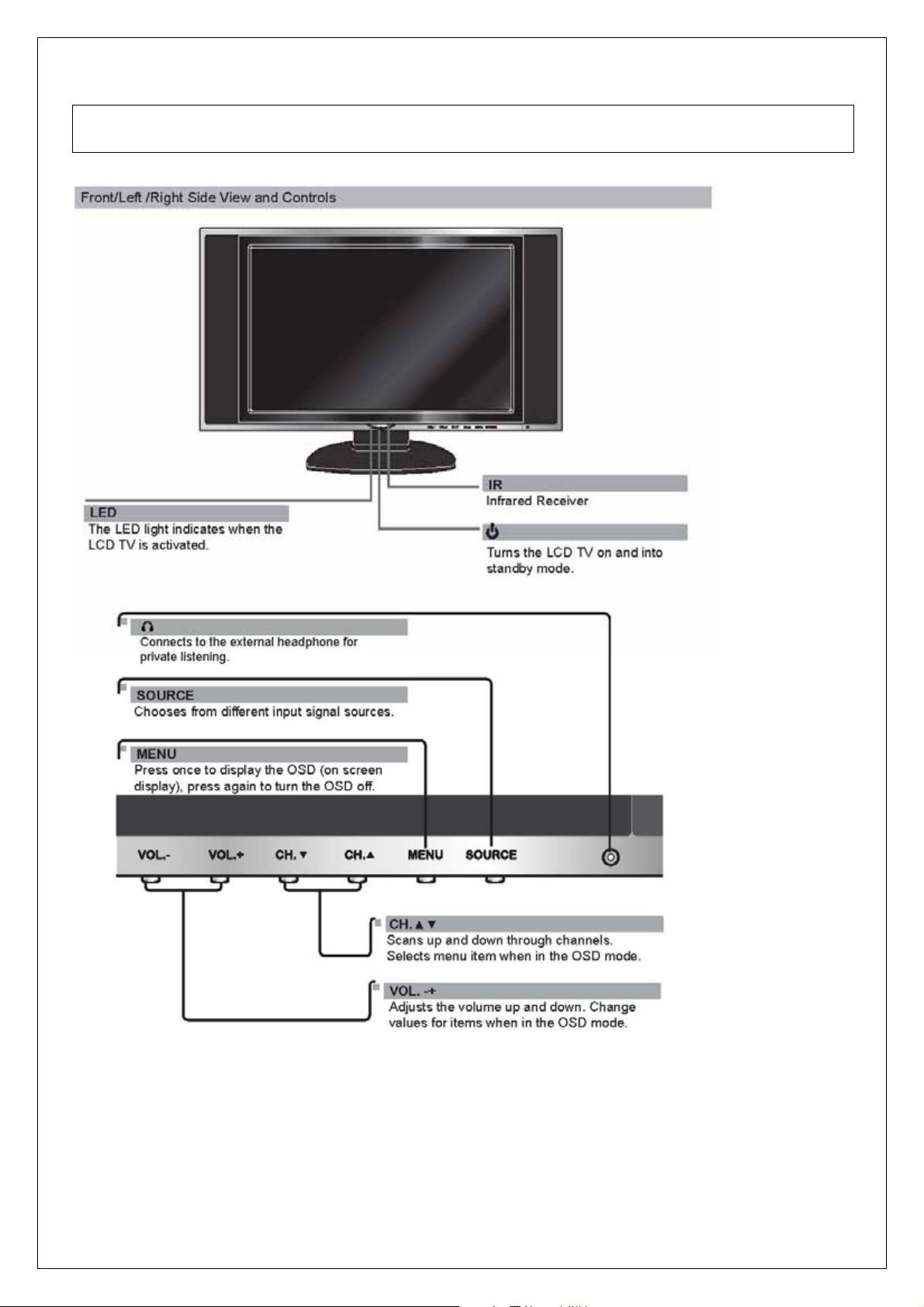
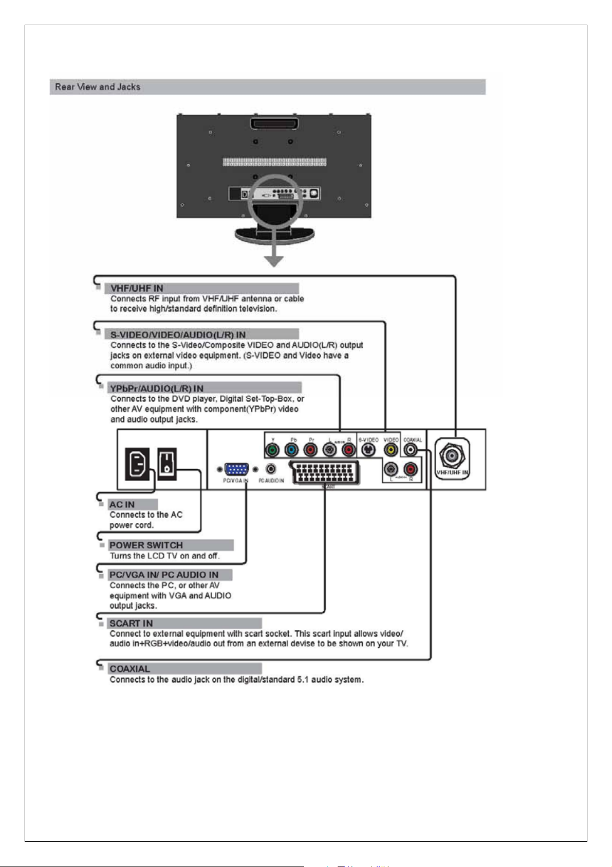
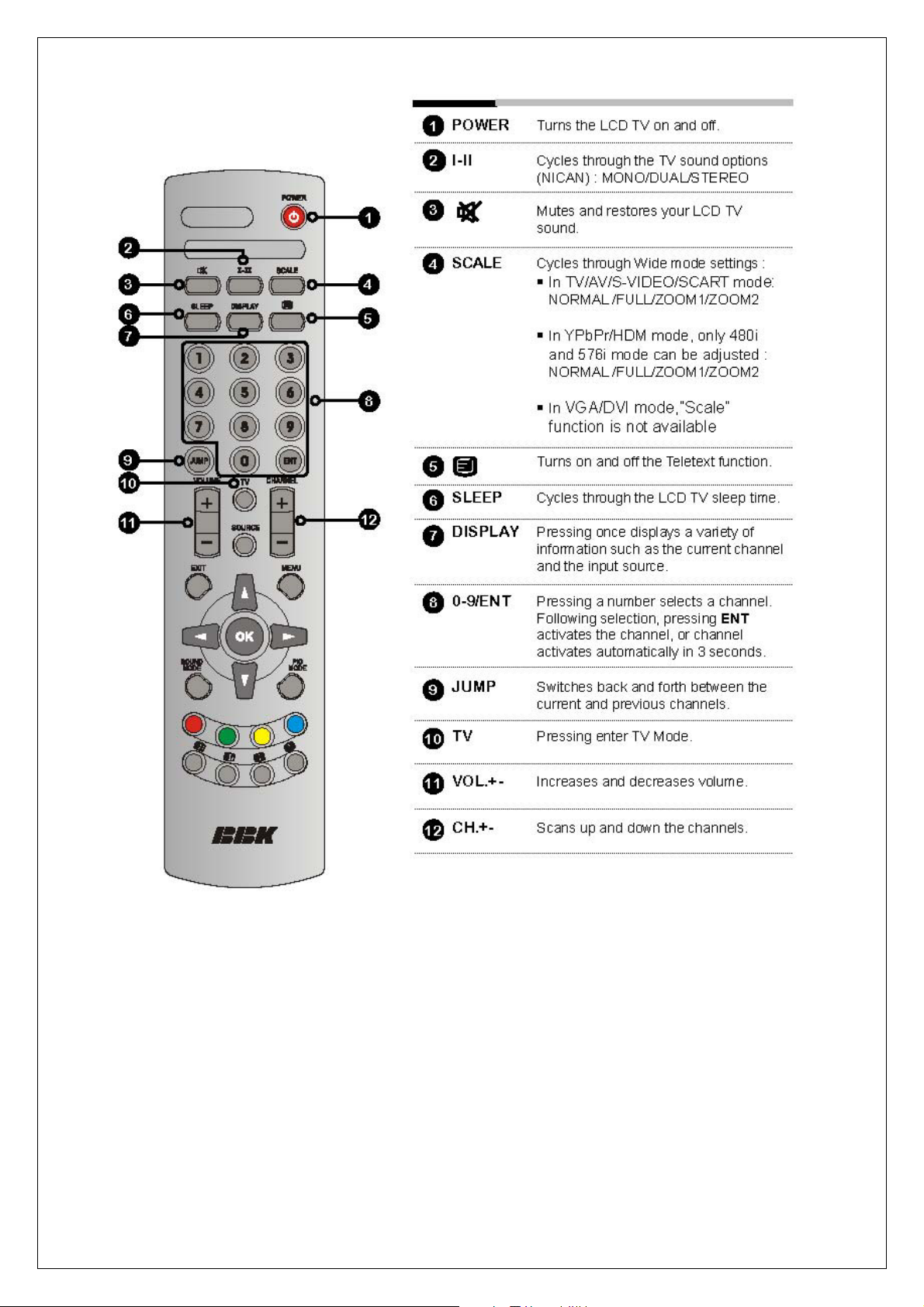
3. Front Panel Function Control Description
Operation, Adjust and Programming
7
Page 10
8
Page 11
9
Page 12

10
Page 13

The operation of each OSD controls is described as following table:
Option Description
User
Game
Movie
Vivid
Sport
Full
Zoom1
Zoom2
Normal
User
Cool
Warm
User
Live
Pop
Rock
Press e/f to change the Picture Mode to be User, Vivid,
Game, Sport, and Movie
Press e/f to adjust the Brightness from 0 to 100
Press e/f to adjust the Contrast from 0 to 100
Press e/f to adjust the Tint from 0 to 100
Press e/f to adjust the Saturation from 0 to 100
to adjust the Sharpness from 0 to 100
e/f
Switch between user, zoom1, zoom2 and normal in all
video mode
Press e/f to select the color Temperature to be User,
Warm, or Cool
Press e/fto change Sound Mode to be User, Live, POP
and Rock
Press e/fto adjust the Volume from 0 to 100
Press e/fto change the Bass from 0 to 100
Press e/fto change the Treble from 0 to 100
Press e/fto adjust the Balance from 0 to 100
Picture
Audio setup
Picture(not
support VGA)
Brightness
Contrast
Tint(not support
PAL)
Saturation
Sharpness Press
Scale (Input
HDMI, YPbPr
(except 480I ) /
VGA source, does
not support scale
function)
Color temp
Sound mode
Volume
Base
Treble
Balance
Osd setup
TV setup
Mute
English,
German,
French,
Language
(待定)
Time out
Transparency
Sleep time
Reset Recall factory setting.
APS Start auto search and auto process
Fine tune Press e/f to adjust the Fine Tune from -50 to 50
Italian,
Spanish,
Portugal,
Holland
Poland
Press e/fto adjust the Mute on or off
Allow you to select a language for all the on-screen menu.
Press e/f to select the Menu Timeout to be 5,10,15,20,25,
30,35,40,45,50,55,60 seconds.
Press e/f to select the Sleep Timer to be 15, 30, 45, 60,
90, 120 minutes or Off.
Add/Erase Allow you to add/remove channels.
11
Page 14

VGA setup
Channel Name Edit the channel name. (Europe only)
Channel Swap Swap the channel location . (Europe only)
Channel reset
Auto Allows you to auto adjust the display mode.
H-Position
V- Position
Clock
Phase
Allow you to restore a default TV channel table. (TV
only)
Allows you to adjust the position of the picture left and right
in the window
Press VOLUME ( -, +) to adjust the Sharpness from 0 to
100
Allows you to adjust the position of the picture left and right
in the window
Press VOLUME ( -, +) to adjust the Sharpness from 0 to
100
AControls the width of the picture based on the VGA mode.
Allows you to improve focus clarity and image stability
Press VOLUME ( -, +) to adjust the Hue from 0 to 100
12
Page 15

4. Adjusting Procedure
ITEM Equipments Requirements Procedure and SPEC
‧ Select SOURCE then choose VGA
Color
Temp.Adustment
White balance
adjustment
a. warm Brightness and
VG828/Croma2327
Chroma 7120
(untouchable)
Contrast =>50
1280*800/60 all white
balance
Select the warm to
enter the adjustment
option of R.G.B.
b. standard Brightness and
Contrast =>50
Select the standard to
enter the adjustment
option of R.G.B
c. cool
Brightness and
Contrast =>50
Select the cool to enter
the adjustment option
of R.G.B
TV mode test Factory TV signal or
S-VIDEO adjsutment
TV signal generator
DVD
S-Video Cable
Output PAL signal
Play DVD
Set DVD to interlaced
output
SACRT output test To accept TV signal Send TV signal
through the SCART
‧ Enter the factory area
‧ Select Calibration
‧ Enter Color Temp. to User
‧ Enter User Color temp and adjust the R
Automatically adjust the value of R.G.B and
adjust the Color Temp. of white image to be
x:313 ± 20,y:316 ± 20Y: 200cd/ m
Automatically adjust the value of R.G.B and
adjust the Color Temp. of white image to be
x:295 ± 20.y:305 ± 20 Y: 200%cd/ m
Automatically adjust the value of R.G.B and
adjust the Color Temp. of white image to be
x:281 ± 20.y:288 ± 20 Y:200%cd/ m
Check if the picture is normally display under
User menu, and it will display snow without
any signal, and then enter the standby mode
after 15 mins without any signal.
Screen is clear and fluent
Screen is clear and fluent
G B offset/gain value
2
2
2
SDTV(Y,Pb,Pr) 576P
480P
HDTV (Y,Pb,Pr)
720p/1080i
HDTV Receiver
ATSC HDTV Tuner
Component Cable
Hard disc player
Play SDTV/HDTV
(Y,Pr,Pb)
13
Screen is clear and fluent
Page 16

V
GA INPUT
VGA INPUT
PC
VGA Cable
TV BOX
D-SUB Cable
z Each Mode can display normally. If there
is a specific Mode that is not appropriate
after switch, press Auto Adjust will to
automatically adjust for appropriate
screen.
z Confirm PC can automated identify the
hd155tpLCD NO.
z Use external-connect TV BOX, watching
the TV program; the screen is clear and
fluent.
z Select SOURCE then choose
S-VIDEO.
z Sending the signal from DVD test disc
(sixth paragraph)
NTSC/PAL Switch
.480P/480i switch
DVD
S-Video Cable
or TV Signal
GENERTOR
”FLUKE 54200” or
approved equipment
Play DVD test disc
VIDEO ESSENTIALS
(A-1)
Set DVD to interlaced
output
DVD
Component Cable or
TVSignalGENERTO
R
”FLUKE 54200” or
approved equipment
Play DVD test disc
VIDEO ESSENTIALS
(A-1)
Set DVD to
progressive output (P-
SCAN)
z Switch DVD output mode from
NTSCand PAL, Watch the
screen to check if has switch
NTSC/PAL
z Select SOURCE then choose
Y CBCR/Y PBPR
z Sending the signal from DVD
test disc(sixth paragraph)
z Switch DVD to output mode P-SCN
ON/OFF
z see if there is the action of switch
(480i/480p).
14
Page 17

.SOUND mode
a. Volume
b. Treble
c. Bass
d.Balance
e.Mute
Pattern Generator
Audio source output
External connect
Left/Right speaker
(2.5/8ohm)
DVD/VCD plays
music or DVD disc
DVD/VCD plays
music or DVD disc
DVD/VCD plays
music or DVD disc
Any Pattern
z Selects SOURCE menu
z Enterthe SOUND adjustment
item.
z Press ▲ /▼ to set audio volume
z Check if the action is normal.
z Press▲ /▼ to set audio volume
z Check if the action is normal.
z The default is”50”
z Press ▲ /▼ to set Bass volume
z Check if the action is normal.
z The default is”50”
z Press ▲ /▼ to set balance
z The default is”50”
z Press ▲ /▼ to set balance
z The default is”off”
Surround Mode
NICAM
Super Freq. test
Remote function test.
.TUNER FLUKE54200
DVD/VCD plays
music or DVD disc
GENERTOR"FLUKE
54200"or approved
equipment
Pattern Generator
VGA Cable
PC
Pattern Generator
TV Signal Generator
DVD or VCD
HDTV Player
15
z Press
z Check if the sound has change
z The default is”OFF”
z Press I-II button on the remote
z Check if the sound has
change.
z Check if OSD displays”super Freq.”
z Check if each function is normal under
each mode
z Selects SOURCE to be TV
z Selects TV SOURCE AIR
z Check if Screen is clear and
fluent
z Selects TV SOURCE CABLE
z Check if Screen is clear and
fluent
to set ON/OFF
Page 18

5. Trouble Shooting Flow Chart
STEP 1.
No NO No
NO
NO
YES
NO
OK
YES
NO
16
No Display
( Black )
LED ON ?
YES YES
Push the power
ON/OFF switch
NO
LED Color
change ?
Check KEY/ LED
board &J7
OK
A
NG YES
Change AD
Board
C
Check AC
Socket ?
YES YES
LCD TV
ON?
Check the A/D board
tuner U16-Pin3
U16-Pin3
High ?
Check Inverter Power
(24V)of LCD Panel, OK?
B
Change AC Socket
Fuse or power board
Check
Video& Audio
Function
Make sure the
LVDS
connection of
LCD Panel is
fine ?
Display ?
Check Video&
Audio Function
Page 19

Check the connection
NO
of Signal cable
YES
YES
YES
NO
YES
YES
NO
Change AD Board
Check Video&
Audio Function
A
Display ?
NO
B
U16-PIN5
Active low(Se
e
Panel SPEC.) ?
Change the LCD
Panel
Display ?
Change AD
Board
Change AD Board
Check Video&
Audio Function
17
Page 20

STEP 2.
NO
NO
OK
No TV,VIDEO
and VGA
Picture
C
Change AD
Board
Check
Video&
Audio
Function
Check
Video&
Audio
Function
OK
STEP 3.
OK OK OK
NG
NG
No Audio
Check
A/D board
J4
Change AD
Check
Speaker
Change Speaker
Check
Video&
Audio
Function
Board or U2
18
Page 21

6. Exploded Diagram and Spare Parts List
19
Page 22

U12
HDMI/DVI
HDMI
RGB/Audio L/R
VGA
Composite/Audio L/R
S-video/Audio L/R
Compoment/Audio L/R
VIDEO/AUDIO
Composite /SIF
AV
S-video
YPbPr
SCART
TV
MST97885LD/96885LD
7. Block Diagram
U9
PANEL
1024*768
U2
Audio amp
U8
Earphone
AMP
U7
DDR
20
Page 23

8. Schematic Diagram
21
Page 24

22
Page 25

23
Page 26

24
Page 27

25
Page 28

26
Page 29

27
Page 30

28
Page 31

29
Page 32

30
Page 33

9. PCB Layout Diagram
Keypad Board (Component Side Top)
Keypad Board (Component Side Bottom)
IR/LED Board (Component Side Top)
IR/LED Board (Component Side Bottom)
32
Page 34

Main Board (Component Side Top)
33
Page 35

Main Board (Component Side buttom)
34
 Loading...