

BBK LD1916DK Service manual

LD1916DK(RU)
9
Service Manual
Model version:M7C1V2.00
M7C2V2.00
7
7

Catalog
Chapter One About Maintenance
1.1 Safety precautions
1.1.1 Power supply
1.1.2 Precautions for antistatic
1.1.3 Precautions for display screen
1.1.4 Precautions for laser head
1.1.5 About placement position
1.2 Maintenance method
1.2.1 Electric resistance method
1.2.2 Voltage method
1.2.3 Current method
1.2.4 Element substitution method
1.2.5 Cutting method
1.2.6 Visualized method
1.2.7 Comparison method
1
1
1
1
1
2
2
2
2
2
2
2
2
3
3
1.3 Required device for maintenance
Chapter Two Functions and Operation Instructions
Section One TV Segment
2.1.1 Features
2.1.2 Set list
2.1.3 Controls and functions
2.1.4 Connection and starting
2.1.5 TV Mode
2.1.6 PC Monitor mode
2.2 Section Two DVD segment
2.2.1 Controls and functions
DVD Function settings
2.2.2
3
4
4
4
5
5
7
7
9
10
10
10

15
2.2.3 DVB Function settings
2.2.4 Others
Chapter Three Principle and Servicing
The previous manual: TV part
Section One Principle of the player
3.1.1 System control principle
OVerall wiring diagram
3.1.2
3.1.3
3.1.6
3.1.7 Block diagram of DVB
Section Two Troubleshooting flow chart
Section Three
Block diagram of the player
Audio circuit
3.1.4
3.1.5
Power circuit
Video circuit
Waveform diagram
12
14
17
17
17
17
18
19
20
20
21
21
23
36
The next manual: DVD part
Section One Principle of the player
3.1.1 Audio circuit
3.1.2 Video
3.1.3 Servo circuit
3.1.4 USB/CARD circuit
3.1.5 Decode circuit
Section Two Troubleshooting flow chart
Section Three
Chapter Four
Chapter Cinque PCB board & Circuit diagram
Section One PCB board
Section Two Circuit diagram
circuit
Waveform diagram
Block Diagram of Play Disassembly and Explosion
45
45
45
45
46
46
47
48
54
59
62
62
66
Chapter Six BOM List
84

Caution :
This Service Manual is applicable to LD1916DK(RU)-2 M7C1V2.00,M7C2V2.00.

Chapter One About Maintenance
- 1 -
1.1 Safety precautions
1.1.1 Power supply
When maintenance personnel are repairing DVD TV, he should pay special attention to the power
with 220V 800V AC and 330V DC which will cause hurt and damage to persons!
1.1.2 Precautions for antistatic
Movement and friction will both bring static electricity which causes serious damages to integrated
IC. Though static charge is little, when a limited quantity of electric charge is added to large
scaleintegrated IC, as the capacitance is very small in the meantime, now the integrated IC is very much
easy to be struck through by static electricity or the performance will decrease. Thus static electricity
prevention is of extraordinary importance. The following are several measures to prevent static
electricity:
1. Use a piece of electric conduction metal with the length of about 2 metres to insert into the earth,
and Fetch the lead wire from the top of the surplus metal and connect to the required static electricity
device. The length and depth of the metal embedded under the earth should be determined according to
the wettability of the local soil. For humid places, it may be shorter, and longer and deeper for dry places.
If possible, it can be distributed and layed in terms of “#” shape.
2. On operating table-board, the antistatic table cushion should be covered and grounded.
3. All devices and equipments should be placed on the antistatic table cushion and grounded.
4. Maintenance personnel should wear antistatic wrist ring which should be grounded.
5. Places around the operating position should also be covered with electric conduction cushion or
Painted with antistatic paint.
1.1.3 Precautions for display screen
1. Display screen is breakable article, so please protect carefully when carrying and prevent fingers
or hard objects striking the screen to damage structure of the screen.
2. When cleaning screen, do not use organic chemicals. You should use cloth and use small
amount of special cleaning liquid in places difficult to clean.

1.1.4 Precautions for laser head
- 2 -
1. Do not stare at laser head directly, for laser emission will occur when laser head is working,
which will Hurt your eyes!
2. Do not use wiping water or alcohol to clean laser head, and you may use cotton swab.
1.1.5 About placement position
1. Never place TV in positions with high temperature and humidity.
2. Avoid placing near high magnetic fields, such as loudspeaker or magnet.
3. Positions for placement should be stable and secure.
1.2 Maintenance method
1.2.1 Electric resistance method
Set the multimeter in resistance position and test whether the numerical value of resistance of each
point in the circuit has difference from the normal value to judge the trouble spot. But in the circuit the
tested numerical value of resistance is not accurate, and the tested numerical value of integrated IC's
pins can only be used for reference, so the elements should be broken down for test.
1.2.2 Voltage method
Voltage method is relatively convenient, quick and accurate. Set the multimeter in voltage position
and test power supply voltage of the player and voltage of a certain point to judge the trouble spot
according to the tested voltage variation.
1.2.3 Current method
Set the multimeter in current position and test current of the player of a certain point to judge the
trouble spot. But when testing in current method, the multimeter should be series connected in the
circuit, which makes this method too trivial and troublesome, so it is less frequently used in reality.
1.2.4 Element substitution method
When some elements cannot be judged good or bad, substitution method may de adopted directly.
1.2.5 Cutting method
Cutting method should be combined with electric resistance method and voltage method to use.
This method is mainly used in phenomena of short circuit and current leakage of the circuit. When
cutting the input terminal voltage of a certain level, if voltage of the player rises again, it means that the
trouble lies in this level.
1.2.6 Visualized method
- 3 -
Directly view whether abnormalities of collision, lack of element, joint welding, shedding welding,
rosin joint, copper foil turning up, lead wire disconnection and elements burning up among pins of
Elements appear. Check power supply of the machine and then use hands to touch the casing of part of
elements and check whether they are hot to judge the trouble spot. You should pay more attention when
using this method to check in high voltage parts.
1.2.7 Comparison method
A same good PC board is usually used to test the correct voltage and waveform. Compared these
data with those tested through fault PC board, the cause of troubles may be found.
Through the above maintenance method, theoretical knowledge and maintenance experience, all
difficulties and troubles will be readily solved.
1.3 Required device for maintenance
Audio Generator
Digital oscillograph ( 100MHE)
SMD rework station
Multimeter
Soldering iron
Pointed-month pincers
Cutting nippers
Forceps
Electric screw driver
Terminals connecting cord
Headphone
Microphone

Chapter Two
- 4 -
Functions and Operation Instructions
2.1 Section One TV SEGMENT
2.1.1 Features
Technical Features
#High quality color TFT panel(15 inch for LD1516DK, 19 inch for LD1916DK )
#Maximum resolution 1366X768 for LD1516DK,1440X900 for LD1906DK.
#Built-in DVD player with Slot-in mechanism
#Multisystem TV tuner with NICAM decoding
#Biuilt-in stereo audio system
#USB port to playback compatible files stored on flash memory of external devises
#Composite video ,audio input
#Component, RGB/SCART and VGA video inputs
#Digital coaxial output for multi-channel sound playback
#Headphones output
#Universal holder for furniture or wall fixation with 270 rotation angle
TV Channels Receiving and External Signal Playback
#DVB-T turner for watching digital TV channels.
#Automatic and fine tuning functions with 100 channels memory
#Adjustable brightness, contrast, saturation, hue and 4 preset image settings
#Tone and sound balance adjustment and 4 preset audio settings
Disc playback mode
#Digital video playback: DVD-Video, Super VCD, VCD compatibility
#MPEG-4 standard support
#Digital audio playback: CD-DA, and HDCD compatibility
#Digital graphic albums playback: Kodak Picture CD and JPEG
#Compatible disc types: CD-R/CD-RW, DVD-R,/DVD-RW, DVD+R/DVD+RW
#Russia, Cls and Baltic States adaptation interface and filenames ID3-tags and CD-Text support
simplifies device operation
#”Q-Play” function provides direct playback and allows to skip commercial that is not possible to
rewind
#”Browser” function provides easy access to playback control
#Automatic screensaver function
#Parental control function to protect children from watching inappropriate discs
#Super wide range of operating power supplies(~100-240v) automatic short circuit protection
PC monitor mode
#Wide resolutions range
#RGB setting and 4 presets of color temperature
#Tone and sound balance adjustment and 4 preset audio settings
#External audio signal playback.
2.1.2 Set list
- 5 -
LCD TV
Remote Control
AAA Battery
Power Adapter
Power Cord
RCA-RCA cord
2XRCA-2XRCA cord
Microphone
Microphone cable
Wall Mount Holder
Screw M5X15
Screw PA5X25
Screw PM4X10
Expandable pipe
User manual
Warranty Card
Karaoke disc
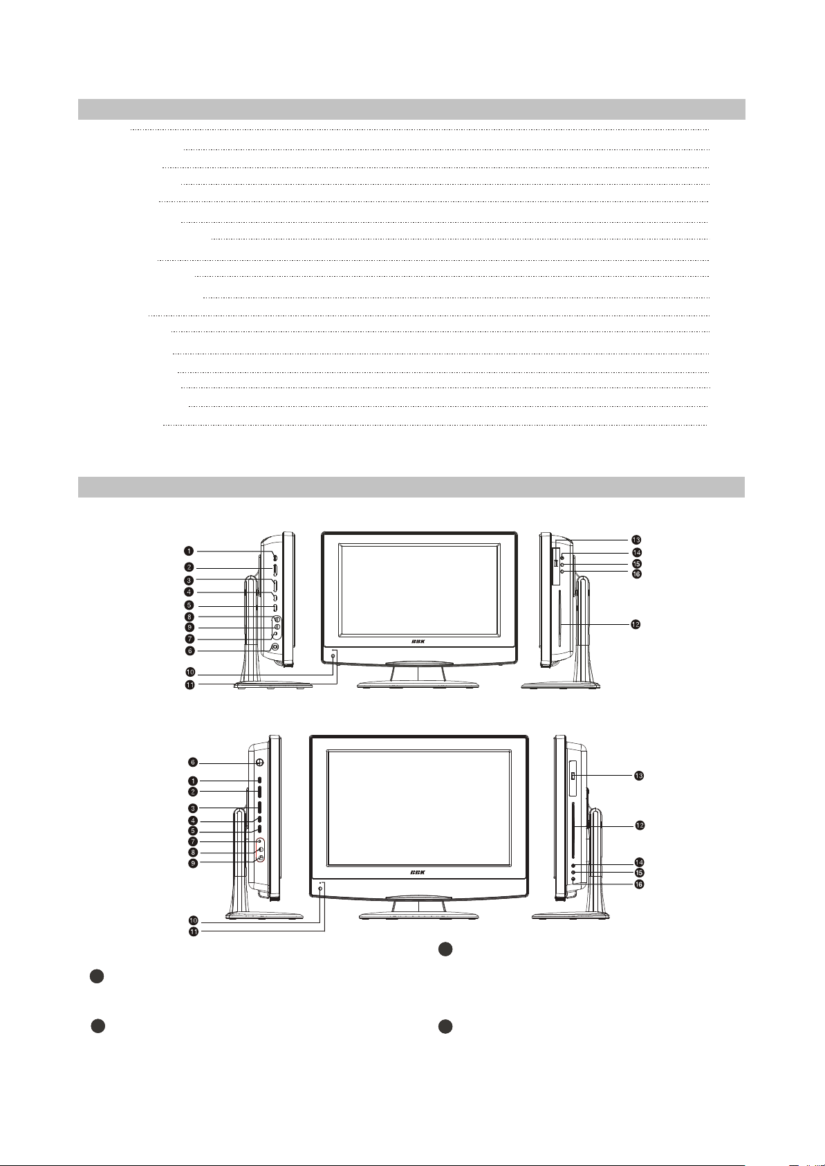
2.1.3 CONTROLS AND FUNCTIONS
(1) Panel controls and indication
1pcs
1pcs
2pcs
1pcs
1pcs
1pcs
1pcs
1pcs
1pcs
1pcs
1pcs
4pcs
4pcs
4pcs
1pcs
1pcs
1pcs
For LD1516DK
For LD1916DK
Left panel
SETUP button
1
Press to switch to setup mode
2
_VOL+button
Press to adjust the volume.
_CH+button
3
Press to switch between channels/to
choose menu item.
4
SOURCE button
Press to choose the playback mode.
STANDBY button
- 6 -
5
Press to switch on the device/into
standby mode.
6
POWER button
Turn on/off the power.
7
Headphones output
Microphone input 1
8
Microphone input 2
9
Front panel
Remote control sensor
10
Power supply indicator
11
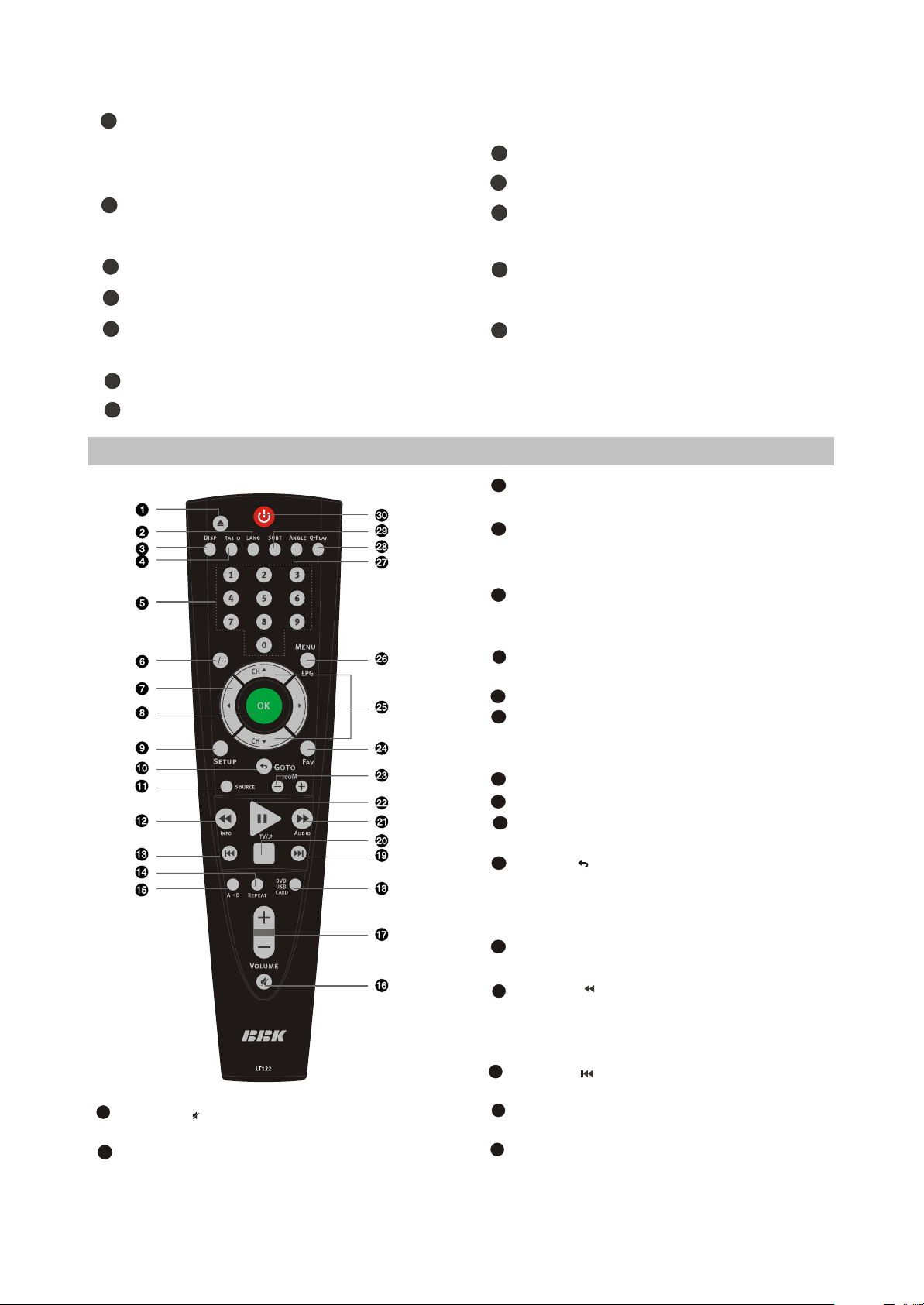
(2) Remote control general view
16
Button
Press to turn on/off the sound.
17
VOLUME+/-button
Press to adjust the volume.
Right panel
12
Disc tray
13
USB port
14
EJECT button
Press to open/close the disc tray.
15
STOP button
Press to stop the playback.
16
PLAY/PAUSE button
Press to playback/pause.
1
EJECT button
Press to open/close the disc tray.
2
LANG button
In DVD and DVB mode, press to change
language..
DISP button
3
Press to display the disc and the current
source information..
4
RATIO button
Press to switch a pect ratio mode.
5
Numeric buttons
6
-/-- button
Press to switch one or two-digit program
number..
7
CURSOR buttons
8
OK button
9
SETUP button
Press to enter setup mode.
10
Button /GOTO
Press to return to the previous channel in
TV and DVB mode/To play from a certain
time point in DVD mode.
11
SOURCE button
Press to change the mode.
Button /INFO
12
Press to start rewind/rewind scanning/To
display the information about channel and
program in DVB mode.
13
Button
Press to skip backward.
14
REPEAT button
Press to repeat.
15
A-B button
Press to repeat the selected section.
18
- 7 -
USB/DVD button
Press to switch between USB/DVD modes.
19
Button
Press to skip forward.
20
Button
Press to stop the playback.
21
Button AUDIO
Press to forward/forward scanning/In DVB
mode, to change sound track between left,
right and stereo.
22
Button /TV/
Press to playback/pause/Switch between
TV and radio modes, valid in DVB mode.
23
ZOOM+/-button
Press to zoom in/out.
24
FAV button
In DVB mode, open favourite channel list.
25
CH button
Press to switch between channels /to
choose menu item.
26
MENU / EPG button
DVD disk menu/PBC function/To display
the program guide valid in DVB mode.
27
ANGLE button
Press to change the camera angle.
28
Q-PLAY button
Press to turn the Q-PLAY mode on.
29
SUBT button
Press to change the subtitles language.
30
Button
Press to switch on the device on/into
standby mode.
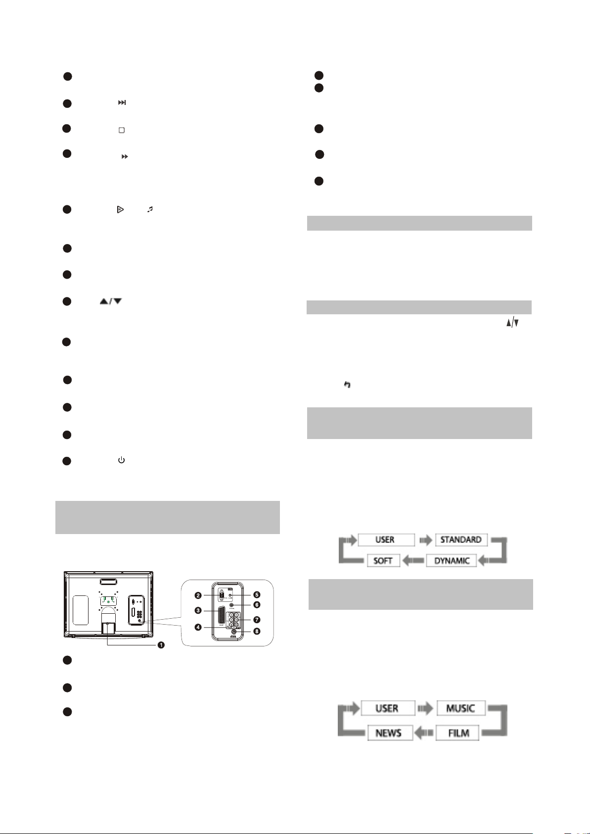
2.1.4 CONNECTION AND
STARTING
SELECT RETURN
ENTER
(1 )Switching interfaces
SETUP
4
Y Cb(Pb) Cr(Pr)
5
PC AUDIO IN
Meant for PC stereo audio output
connection.
COAXIAL OUT
6
Meant for multi-channel sound playback.
7
AUDIO VIDEO IN
Used for external signal source connection.
8
12 V socket
Meant for adapter connection.
2.1.5
TV MODE
This LCD TV can store up to 100 channels
and enables to scan channels thought automatic,
manual and fine tuning scanning mode. Built-in
TV tuner supports stereo audio playback in
NICAM system.
(1) Adjusted channels selection
#Press +CH-buttons on the left panel or CH
buttons on the remote control each time, when
you want to change a channel.
#Use numeric buttons to enter the number of the
channel.
#Press button to return to the previous
channel.
(2) Default picture settings
selection
#You may select one of the default picture
settings:
USER, STANDARD, DYNAMIC and SOFT.
#You may adjust necessary parameters in the
device menu.
#Turn to Picture item on this page for details.
For LD1516DK and LD1916DK
1
RF input
Meant for antenna connection.
2
VGA port
Meant for PC connection.
3
SCART socket
Meant for external audio video signal
source connection. There is no need to
use additional audiocord.
(3) Default sound settings
selection
#You may select one of the default sound
settings:
USER, MUSIC, FILM and NEWS.
#You may adjust necessary parameters in the
device menu.
#Turn to page.13 for details.
(4 )Accompanying sound type
- 8 -
#Only some of the TV channels have stereo
accompanying sound in NICAM system.
#Press NICAM button to select accompanying
sound.
(5 ) TV settings
#Press SETUP button to display the menu.
#Use cursor buttons on the remote control or
+CH-buttons on the left panel to select the item.
Use buttons to adjust selected parameter.
Use OK button for confirmation. Press SETUP
button again to return to the main menu or to
exit TV SETUP.
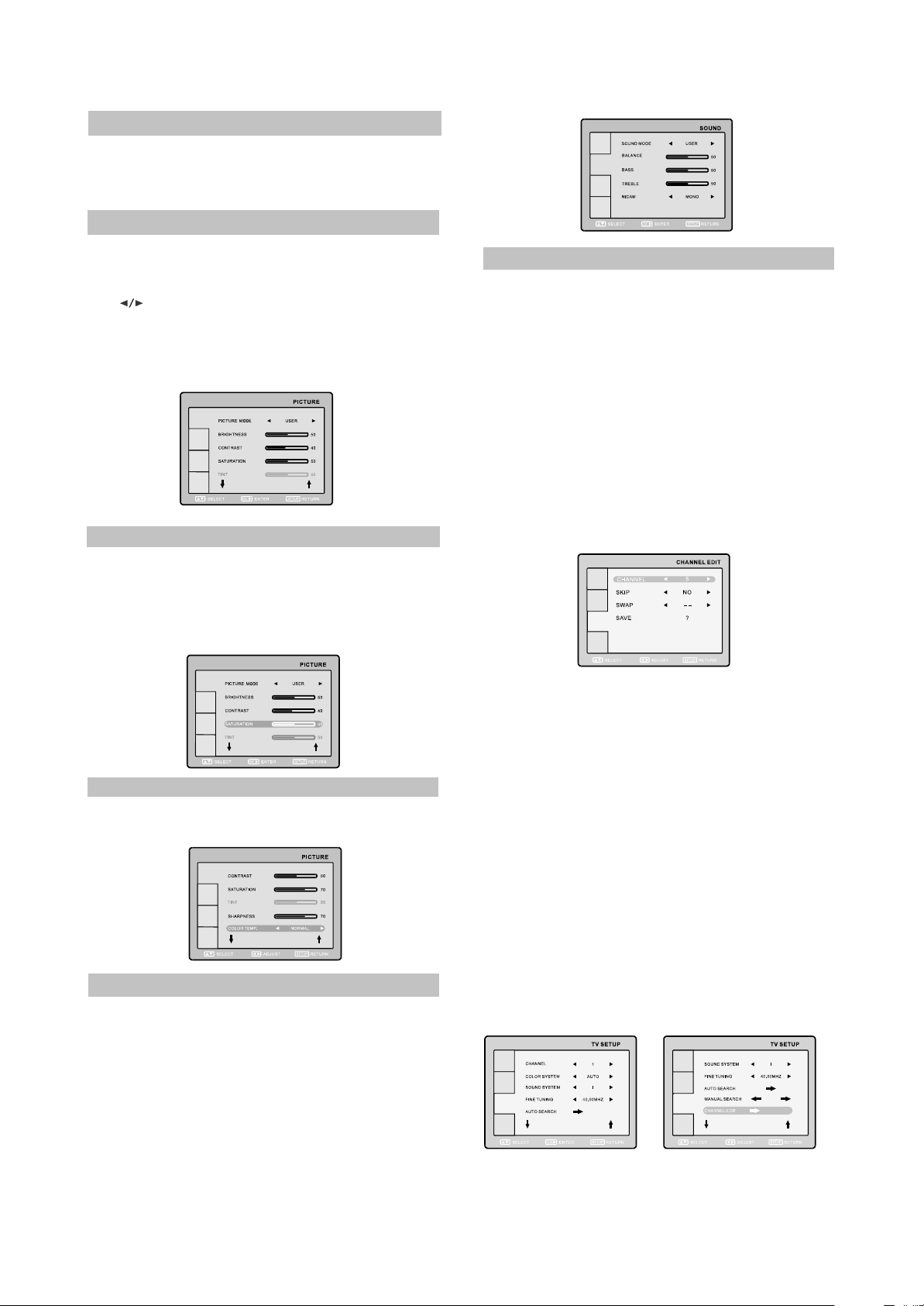
(6) Picture
#Select PICTURE item to adjust picture
parameters.
#You may adjust BRIGHTNESS, CONTRAST,
SATURATION, TINT, SHARPNESS and COLOR
TEMP.
(8) TV setup
Select TV SETUP item to adjust channels.
CHANNEL, COLOR SYSTEM, SOUND
SYSTEM, FINE TUNING, AUTO SEARCH,
MANUAL SEARCH and CHANNEL EDIT.
#CHANNEL item enables to select the number of
adjustable channel.
#CHANNEL EDIT submenu enables to select,
skip and swap the channel.
RETURN
SETUP
#CHANNEL parameter enables to select current
channel.
#SKIP function enables to make current channel
inaccessible while using +CH-button to browse
channels.
NOTE
You can’t adjust TINT while watching TV
channels.
(7) Sound
#Select SOUND item to adjust sound
parameters.
#You may adjust BALANCE, BASS, TREBLE
and NICAM.
ATTENTION! We recommend watching TV at
halfof maximum level of the sound. Continuous
listening at higher level may lead to hearing
reduction.
#SWAP function enables to select the channel
number to swap with current channel.
#SAVE parameter enables to confirm the swap
function.
#FINE TUNING item enables to adjust the
channel frequency accurately.
#MANUAL SEARCH item enables to change
channel settings.
#AUTO SEARCH item enables to adjust channel
setting automatically.
#COLOR SYSTEM item can be changed
between: AUTO, PAL and SECAM. We
recommend to set this item to AUTO.
#SOUND SYSTEM item can be changed
between: B/G, D/K, Land I.
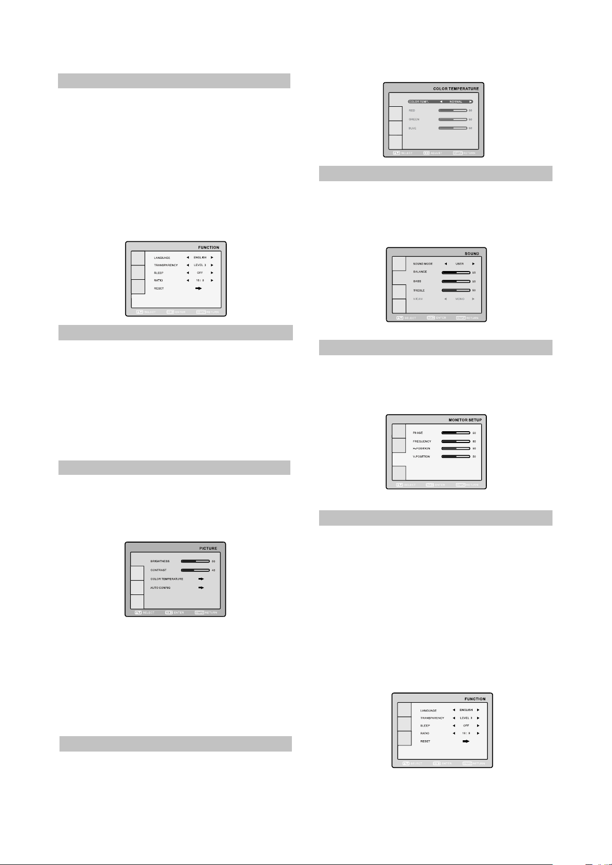
(9) Function
- 9 -
You may select LANGUAGE,
TRANSPARENCY, SLEEP and RATIO.
#LANGUAGE item enables to select the OSD
language.
#TRANSPARENCY item enables to adjust
transparency of OSD.
#SLEEP item enables to set the sleep timer.
#RATIO item can be changed between 16:9 and
4:3,ZOOM1 and ZOOM2.
#RESET item enables to reset all values to
default.
(10) Video settings
#Press SETUP button to display the menu.
#In external video signal playback mode the
menu is the same as the menu, described on
pages 12and 13.
NOTE:
In external video signal playback mode TV
SETUP item is inaccessible.
(2)Sound
Select SOUND item to adjust sound
parameters.
You may adjust BALANCE, BASS, TREBLE
and NICAM.
(3)Monitor setup
Select MONITOR item to adjust such
parameters as PHASE, FREQUENCY, HPOSITION and V-POSITION.
2.1.6 PC MONITOR MODE
(1)Picture
Select PICTURE item to adjust picture
parameters.
You may adjust BRIGHTNESS, CONTRAST,
COLOR TEMPERARURE and AUTO CONFIG.
#Select COLOR TEMPERATURE subment to
adjust color temperature of the picture.
#COLOR TEMP. Item can be set to :USER,
NORMAL, WARM and COOL.
#RED, GREEN and BLUE items enables to
adjust RGB value of color temperature.
#Use AUTOCONFIG to configure display
parameters automatically.
NOTE:
The picture can be displayed incorrectly
while adjusting.
(4)Function
You may select LANGUAGE,
TRANSPARENCY, SLEEP and RADIO.
#LANGUAGE item enables to select the OSD
language.
#TRANSPARENCY item enables to adjust
transparency of OSD.
#SLEEP item enables to set the sleep timer.
#RATIO item can be changed between 16:9 and
4:3,ZOOM1 and ZOOM2.
#RESET item enables to reset all values to
defaule except ratio function.
2.2 Section Two DVD SEGMENT
- 10 -
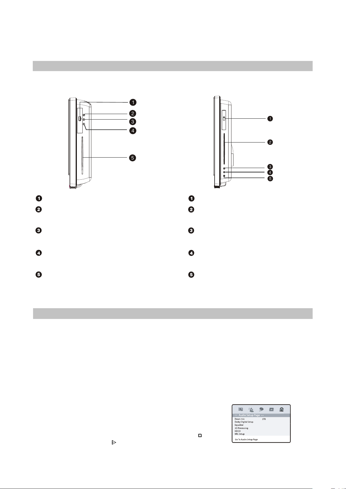
2.2.1 Controls and functions
Front panel controls
For LD1516DK
For LD1916DK
USB port
EJECT button
Press to open/close the disc tray.
STOP button
Press to stop the playback.
PLAY/PAUSE button
Press to playback/pause.
Disc tray
Note:
This model does not support the 8cm disc. Do not insert that type of disc into this device to avoid disc
jam.
USB ports
Disc tray
EJECT button
Press to open/close the disc tray.
STOP button
Press to stop the playback.
PLAY/PAUSE button
Press to playback/pause.
2.2.2 DVD FUNCTION SETTINGS
(1) General setup
1.TV Display: This item is used to set the output picture ratio of this unit.
#Optional settings: Normal/PS, Normal/LB, Wide Squeeze; Default: Wide.
2.OSD language: This item is used to set the OSD language.
#Optional settings: English, Russian; Default: English.
3.Screen Saver: Open or close the screen saver.
#Optional settings: On, Off, Default: Off.
4.Last Memory: This player can save the currently played time point automatically when you leave the
current DVD disc playback(switch from DVD signal source to other signal source, enter standby state in
DVD mode.)
#Optional settings: On, Off. Default: On
NOTE:
When switching to DVD playback state again, this player can
automatically search the time point saved last time to continue
playing. If you want to play from the beginning. Please press
button Twice and then press button.
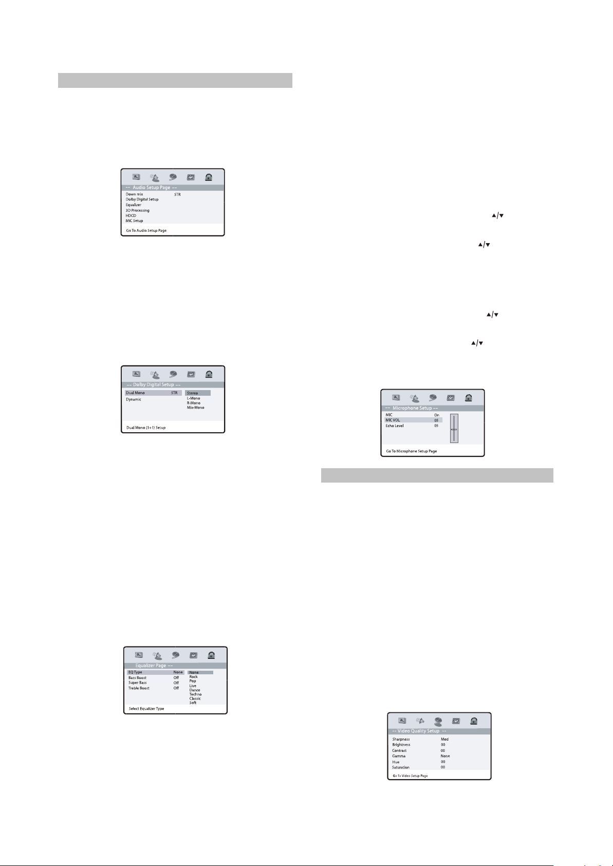
(2) Audio setup
- 11 -
1.Down mix mode: this item is used to set this
unit’s DOWN MIX mode to change multi channel
audio into 2-channel audio output.
#Optional settings: LT/RT, Stereo;
#Default: Stereo
2. Dolby Digital Setup:
Dual Mono:
#Optional settings: Stereo, L-Mono, R-Mono,
Mix-Mono;
#Default: Stereo
Dynamic:
#Set Dolby digital sound dynamic level,
#Default: Off.
5. HDCD: Set filter mode.
#Optional settings: Off, 1X, 2X;
#Default: 1X.
6. MIC Setup:
This item may be used to set volume and echo
of microphone.
MIC: Set MIC switch.
#Optional settings: On, Off; Default: On.
MIC VOL:
Volume adjustment of microphone.
# In micrpohone setup page, press button
to select “MIC VOL” item and press OK button
to enter adjustment menu. Press button to
adjust setup value. After adjustment, press OK
button to return to microphone setup page.
Echo Level:
Echo adjustment of microphone.
#In micrpohone setup page, press button to
select” Echo Level” item and press OK button to
enter adjustment menu. Press button to
adjust setup value. After adjustment, press OK
button to return to microphone setup page.
3.Equalizer:
#EQ Type:
Set equalizer type, optional settings: None,
Rock, Pop, Live, Dance, Techno, Classic, Soft;
Default: None.
#Bass Boost:
Enhance low frequency sound level, optional
settings: On, Off, default: Off.
#Super Bass:
Enhance very low frequency sound level,
optional settings: On, Off .default: Off.
#Treble Boost:
Enhance high frequency sound level, optional
settings: On, Off, default: Off.
--
4.3D Processing: Set reverberation mode.
#Optional settings: Off, Concert, Living Room,
Hall, Bathroom, Cave, Arena, Church;
#Default: Off.
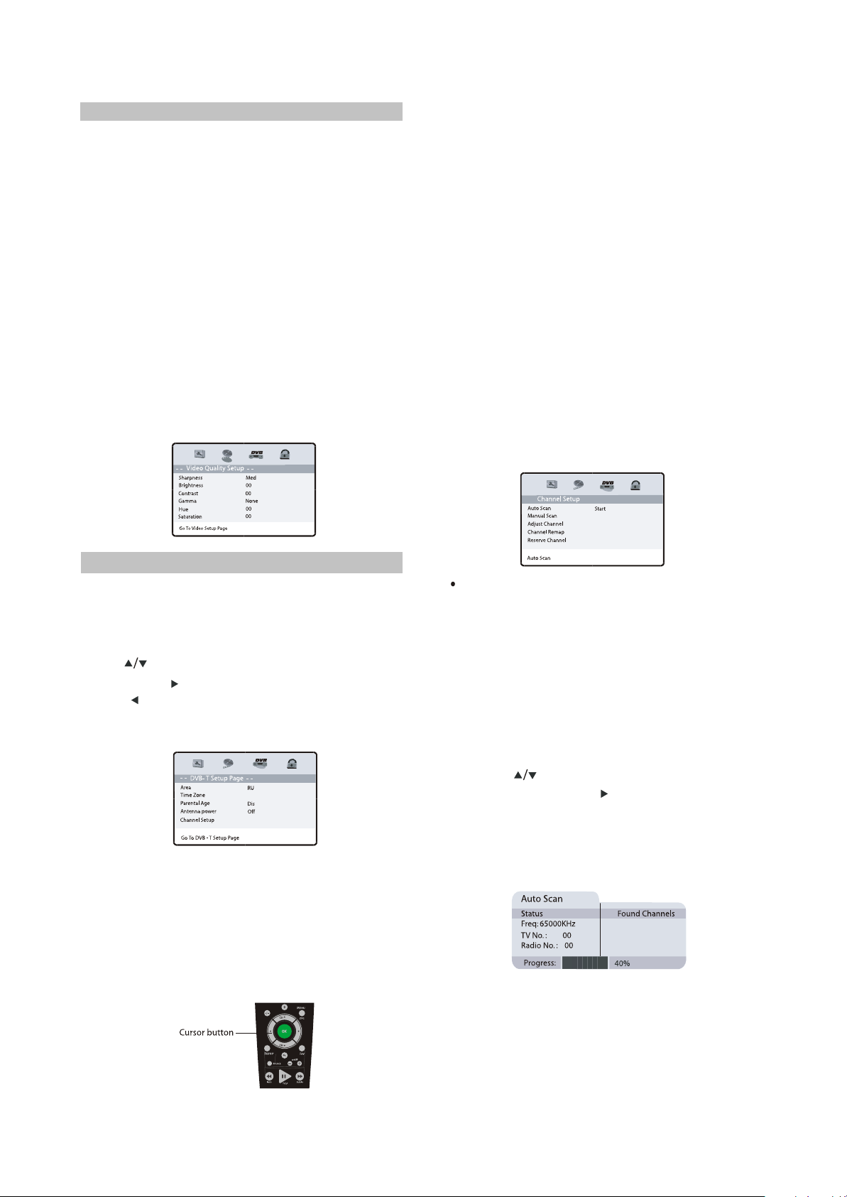
(3) Video setup
1. Sharpness: This item is used to set the
sharpness of video outputs.
#Optional settings: High, Medium, Low; Default:
Med.
2.Brightness: This item is used to set the
brightness of video outputs.
3.Contrast: This item is used to set the contrast
of video outputs.
4.Gamma: This item is used to set the color
temperature of video output.
#Optional settings: High, Medium, Low, None;
#Default: None.
5.Hue: This item is used to set the hue of video
outputs.
6. Saturation: This item is used to set the
saturation of video outputs.
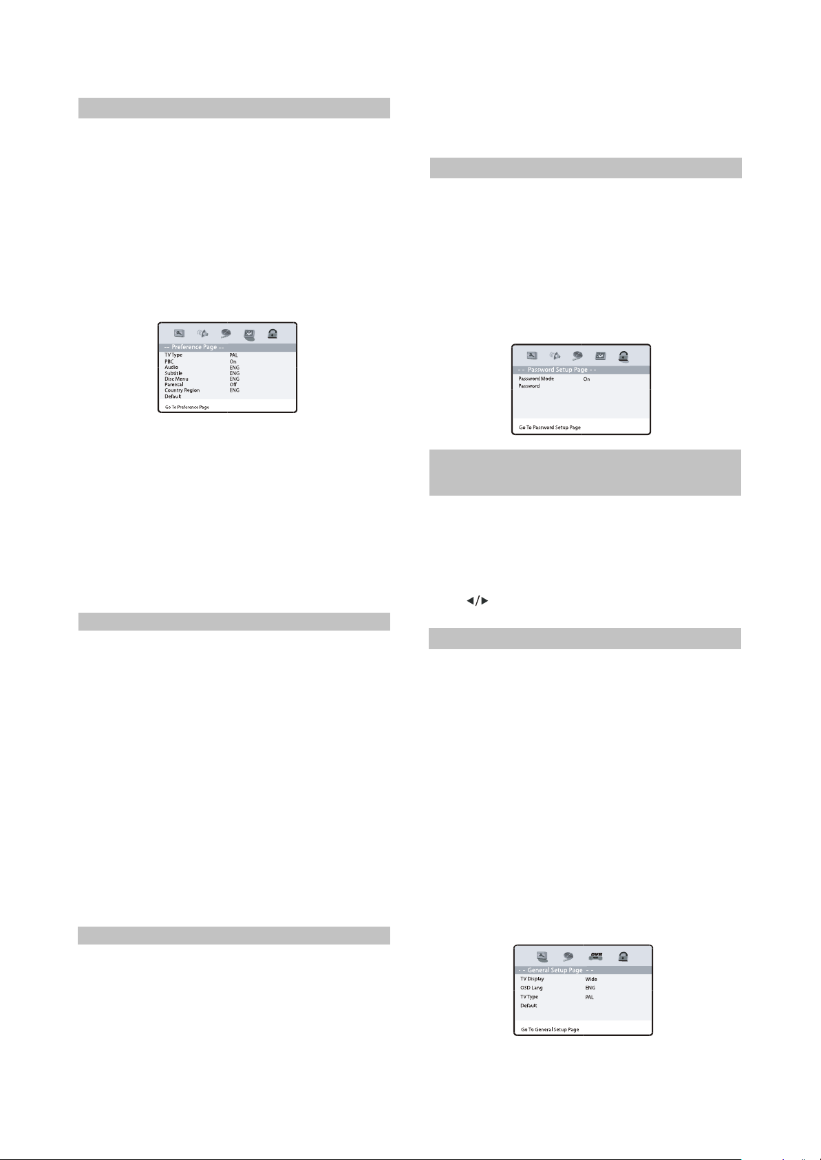
(4) Preference setup
- 12 -
1. TV Type: To set the output video system of this
player.
#Optional settings: PAL, Auto, NTSC; Default:
PAL.
2. PBC: To set the PBC status.
#When playing SVCD, VCD2.0 discs, if PBC is
set On, this unit enters PBC playback mode; if
PBC is set Off, the unit will play the disc
according to track sequence.
Optional settings: On, Off; Default: On.
3.Audio:
This item is used to set the preference audio
language when playing.
4.Subtitle:
This item is used to set the preference subtitle
language when playing.
5.Disc menu:
This item is used to set the preference disc
menu language when playing.
#Default of disc menu language: English
NOTE:
#Audio, subtitle and disc menu language are
only effective in DVD mode.
#If the disc is not recorded with the language you
appointed, the unit will apply the language that
the disc appointed to play.
#Select other languages: press button to move
cursor to “OTHER” item. Press OK button and
then number buttons to input the language code
you desired. After input finishes, press OK button
again.
6.Parental: this item is used to set the parental
control ratings to prevent children from watching
restricted contents.(In the event the disc
supports this function)
#Optional settings: KID SAFE, G, PG, PG
13,PGR,R,NC17,ADULT, Off, Default: Off.
NOTE:
#When changing the parental control ratings, a
password is needed. Please refer to the
following password item for details.
7.Country Region: Set the country region
according to your country.
8.Default: This item is used to restore all settings
to the default value except” Parental control” and
“ Password” in the setup menu.
(5) Password setup
Password: This item is used to set a six digit
password to enable you to change the parental
control ratings.
Password Mode: To set whether parental control
function needs a password, optional setting: On,
Off; Default: On.
Password: To change the password of the
parental control function, default:000000.
2.2.3 DVB FUNCTION
SETTINGS
Turn on the TV. Press SOURCE button to
change source to DVB, then you can enjoy the
rich and colorful contents of Digital Video
Broadcast!
In DVB mode, press SETUP button, then
press button to choose DVB item, the DVB
setup menu will be displayed as follow:
(1) General setup
1.TV Display: This item is used to set the output
picture ratio of this unit.
#Optional settings: Normal/PS, Normal/LB, Wide
Squeeze; Default: Wide.
2.OSD language: This item is used to set the
OSD language.
#Optional settings: English, Russian; Default:
English.
3.TV Type: To set the output video system of this
player.
#Optional settings: PAL, Auto, NTSC; Default:
PAL.
4.Default: This item is used to restore all settings
to the default value except” Parental control”
and “Password” in the setup menu.
(2) Video setup
- 13 -
1.Sharpness:This item is used to set the
sharpness of video ouputs.
#Optional settings: High, Medium, Low; Default:
Med.
2.Brightness: This item is used to set the
brightness of video outputs.
3.Contrast: This item is used to set the contrast
of video outputs.
4.Gamma: This item is used to set the color
temperature of video output.
#Optional settings: High, Medium, Low, None;
Default: None.
5.Hue: This item is used to set the hue of video
outputs.
6.Saturation: This item is used to set the
saturation of video outputs.
2.Time zone
To choose your time zone, it is set depending
on your country. If you don’t know the exact time,
please ask local time manage department.
Default:03:00
3.Parental age
This item is used to set the parental control
ratings. To prevent your children watching
undesired programmes.
#Optional settings:
4,5,6,7,8,9,10,11,12,13,14,15,16,17,18, Disable
Default: Disable
4.Antenna power
Turn on/off antenna power supply. Optional
settings: On. Off; Default: Off
5.Channel setup
This item is used to search channels, edit the
channel list or your favourite channel list. View
program guide information, etc.
(3) DVB-T setup
The DVB-T Setup Page is composed of five
parts: Area, Time Zone, parental Age, Antenna
Power, Channel Setup.
Note:
Press button to select different item, and
press OK or button to enter it.
Press button to return to the previous menu
or to exit the current menu.
1.Area
You can choose the area of your country.
Optional settings: Australia, Austria, Belgium,
Russian, Denmark, Estonia, Germany, Spain,
France, ltaly, Netherland, Taiwan, Others;
Default: Russian.
Note: you must set the correct area before
searching channels.
GOTO
- -
- -
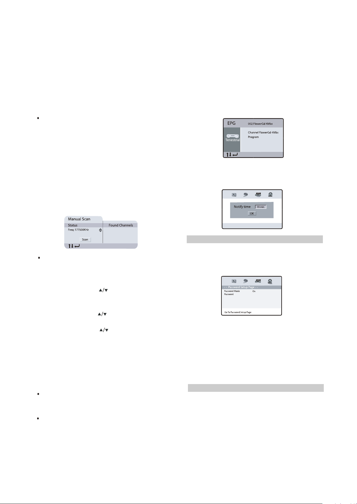
Auto Scan
Connect the antenna to the Therefore socket
on the TV, if the antenna needs a power supply,
turn on/off antenna power supply in the menu.
Then you can automatically search channels
without entering any other information.
In the scan process, the scan result will be
displayed in the Auto Scan window.
Press SETUP button to enter setup menu, then
choose the DVB item;
Using the button to select the Auto Scan
item, and press OK or button to select Start
item, then press OK button;
A prompting message will be displayed to
request that you confirm, select” OK” and press
the OK button to confirm.
Note: If you press the SETUP button during
scanning, the operation is stopped and a
prompting message will be displayed at the
buttom of Auto Scan window. Select” OK” and
press [OK] button to abort auto scan operation,
and the channels found until then will be saved.
And select “ Cancel” and press OK button to
- 14 -
return to auto scan process. Wait while the TV
searches for the channels, this may take a few
minutes.
Once you press OK button to start auto
search operation, all the saved channels will be
cleared.
Please don’t press any button during the course
fo default operation.
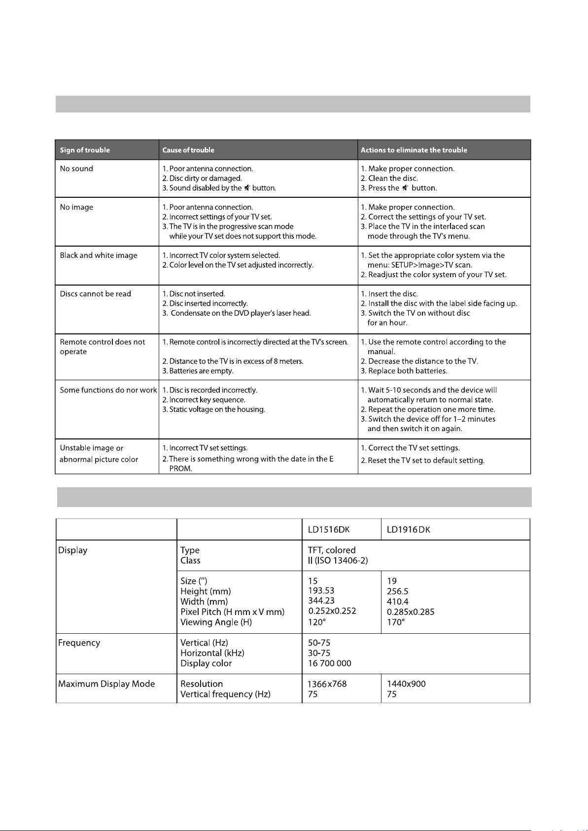
Manual scan
1. In setup menu, select” Manual Scan”, a
manual scan will be shown as follows:
2. Enter the frequency you want to scan by the
number buttons, then press “OK”, the scan
button seems be pressed, press “OK” again to
scan, a scan sign: scanning will be shown on the
window.
3. The scan result will be displayed on the right
halt of the manual scan window, you can save
the found channels or delete them if the TV has
the same program.
When playing a program on a channel, press
EPG button, then a program information list of
current channel will be displayed in a window,
move the cursor to PROGRAM, then press OK
button, a more detailed program list will be
displayed, move the cursor to the program which
you want to watch, then press OK button on
remote control as shown in the window. The
program is saved in your reserved channel.
DVB
You can set the time when the reminding
signal should be displayed before the program
starts.
Adjust channel
You can set your favorite channel, set
parental control age for some channels or delete
channel in Adjust Channel window.
1. Select channel using button, Press number
button 1 to set this channel as one of your
favorite channels.
2. Select channel using button, if you don’t like
this channel press number button 2 to skip it.
3. Select channel using button, press number
button 3 to set this channel as a protected one,
to prevent children from watching the undesired
program.
Note: If you set a channel protected, a password
will need to be inputted in the Protect Channel
window.
The default a password is 000000.
Channel remap
You can change every channel position as
you like in channel remap window.
Reserve channel
If you want to watch a special program on a
channel at a later time, you can reserve it. Then
a reminding signal will be displayed on screen
several minutes before it starts.
(4) Password setup
Password: This item is used to set a six digit
password to enable you to change the parental
control ratings.
Password Mode:
To set whether parental control function needs a
password, optional setting: On, Off; Default: On.
Password:
To change the password of the parental control
function, default:000000
2.2.4 OTHERS
(1) Useful notes
#To extend the service life of your LCD TV make
pauses of not less than 30 seconds between
switching off and repeatedly switching on the
LCD TV.
#Disconnect the LCD TV from the wall outlet
after shutdown.
#Some LCD TV’S functions may not be applied
to some discs.
#Use supply sources of rated voltage, otherwise the LCD TV may not function or be damaged.
- 15 -
#In case of the LCD TV’s occasional stops, please switch the power supply off and then on again.
(2)Trouble shooting
Please check probable causes of malfunction before addressing the service center.
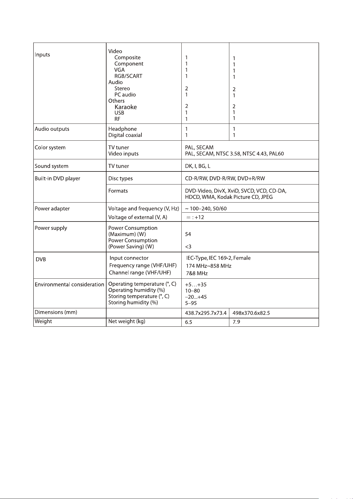
(3) Technical characteristics
- 16 -
#We are permanently improving the quality of our products; hence the product’s design, functionality
and technical characteristics may be modified without prior notice.
#We do not guarantee that all discs can be played smoothly due to the disc quality, disc recording quality
and recording format.
Chapter Three Principle and Servicing
- 17 -
The previous manual: TV part
Section One Principle of the player
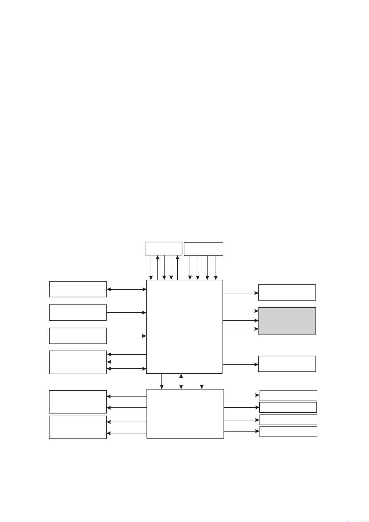
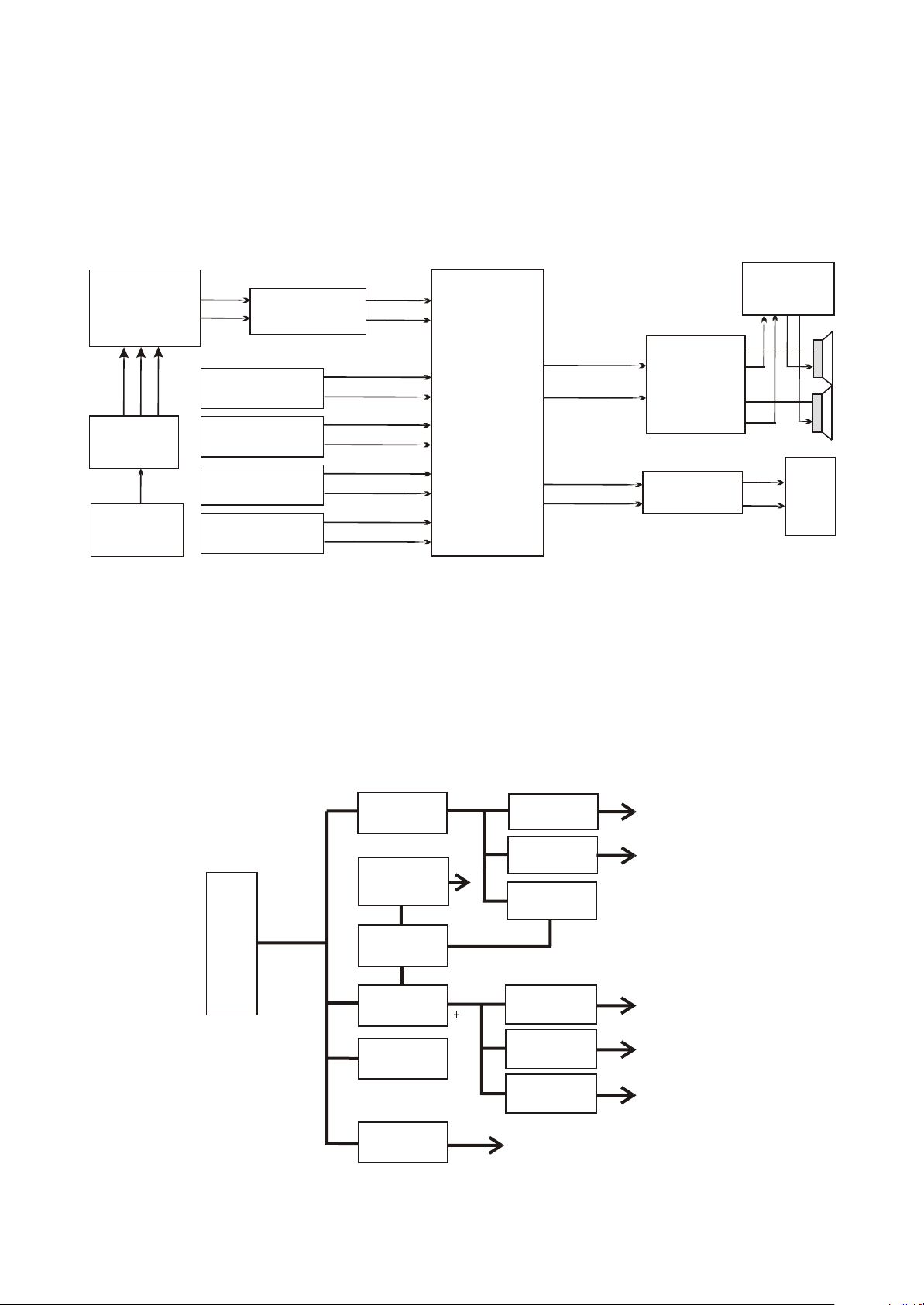
3.1.1 System control principle
System control schematic diagram is shown in the figure 3.1.1.1:
Key-press board
Reset circuit
Remote control board
MT1389HD
Mute control circuit
FSAV433
KEY1~KEY5
RESET
IR
DVSTB
DVSCK
DVSDA
MUTE
ONMUTE
VS1
VS2
U104
PS25LV010
SPIDI
SPICZ
SPIDO
WP
SPICK
SCART JACK
S
FB
S
U101
IC-MST718MCU
T4094
Serial/parallel converter
VSDA
U102
CD4094
VSCK
X
SCLT
RX
SDA
INVERTER
ON/OFF
PANEL_ON
FCLK
FDATA
FCS
ASW
8216_RST
STBY
FMUTE
Inverter components
Emitting module of RF
BH1418
PANEL_ON
control circuit
DVB Moduie
STV8317
power control circuit
BH1418
Figure 3.1.1.1 System control schematic diagram
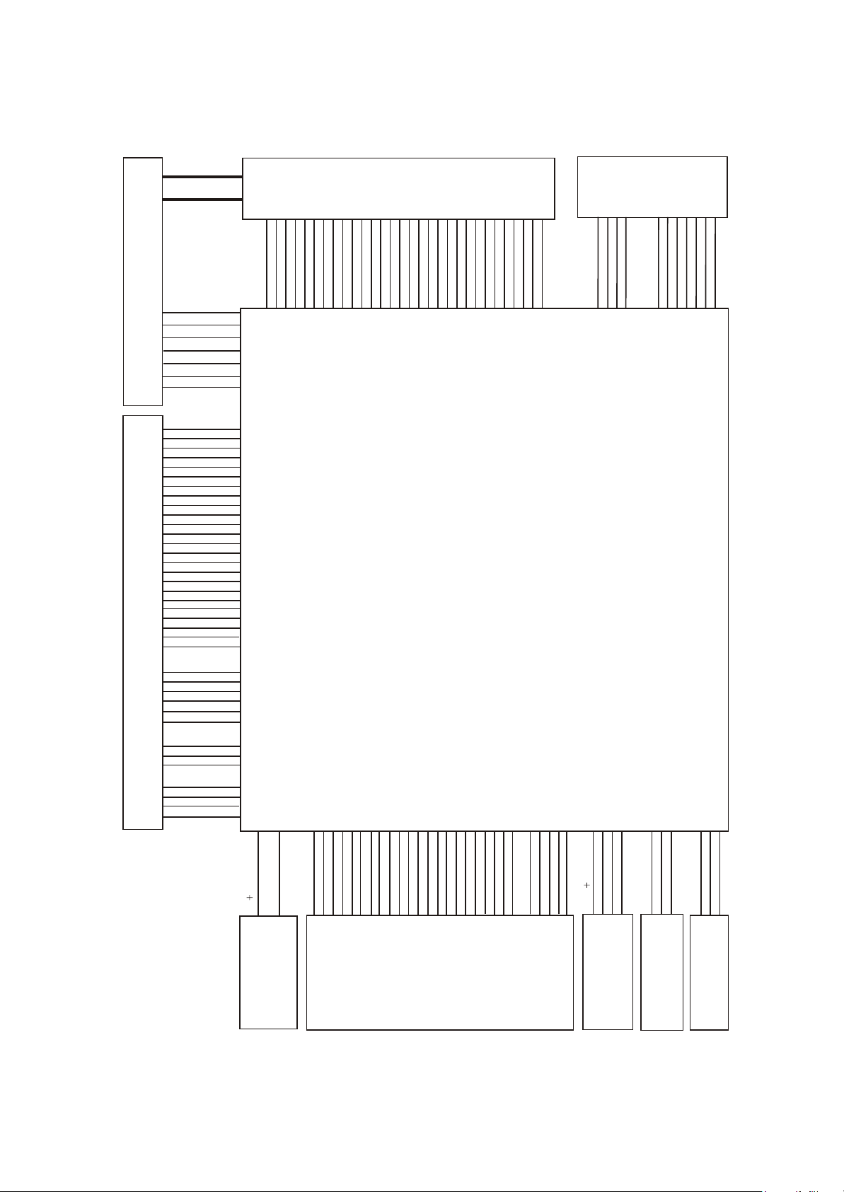
3.1.2 OVERALL WIRING DIAGRAM
PANEL
1234567891011121314151617181920212223242526272829
M156B1-L01 15" TFT
1210554
EARPHONE&MIC
PHONE BOARD
61901-2
4941233
30
CN102
CN701
5IN403-2
INVERTER BOARD
5462457
DVD-PICK UP
DVD LOARD
TD-S208-62SV1 PICKUP
2380370
GND
+12V
+12V
Brightness
GND
BLON
GND
GND
LD-DVD
NC
+5V
MDI
LD-CD
VRDVD
VRCD
NC
E
+5V
V20
GND
F
B
A
RFO
IOA
D
C
TKTK+
FC+
FC-
SL-
SL+
LIMIT
GND
SP+
SP-
TROUT
DISCEJT
GND
+5V
TRIN
GND
+5V
CN101 CN103
CN107
CN108
CN119
J501
GND
GND
ARPLIN-
CN113
AMPROUT-
AMPROUT+
AMPRIN+
GND
+12V
DET#
OKA
LVACKP
LVA3 M
LVA3 P
GND
GND
GND
GND
VCC-PANEL
VCC-PANEL
VCC-PANEL
LVACKM
LVA2 P
LVA1 P
LVA1 M
GND
LVA2 M
LVA0 P
GND
LVA0 M
GND
LVBCKM
LVA3 P
LVA3 M
LVBCKP
LVB0P
LVB1M
LVB0M
LVB1P
LVB2M
LVB2P
CN111
GND
CN2
MAIN BOARD
21901-4
4941840
CN110
CN102
CN105
CN104
CN106
LD1916DK
Block diagram
for machine
0
1
MSD
MSD
MSD2#
12VSW
GND
5449509
@5AK0833-0
POWER ADAPTER
figure 3.1.2.1 overall wiring diagram
CLK
D
S
MSD3#
GND
SDCLK
USB_SWITCH
M
GND
MSBS#
SDCMD
GN
MSINS
SDCD
GND
SDD0
4941842
D1903-4
CRAD&USB
BOARD
M
BP
S
Dv33
GND
SDD1
SDD2
SDD3
GND
USB
GND
U
5VEXT
GND
IR
STBY
KEY1
+5V
+5V
B1903-3
REMOTE BOARD
GND
4942009
DVD KEY BOARD
GND
SW1
KEY2
J1903-0
SW2
41903-0
5449477
5449438
TV KEY BOARD
- 18 -
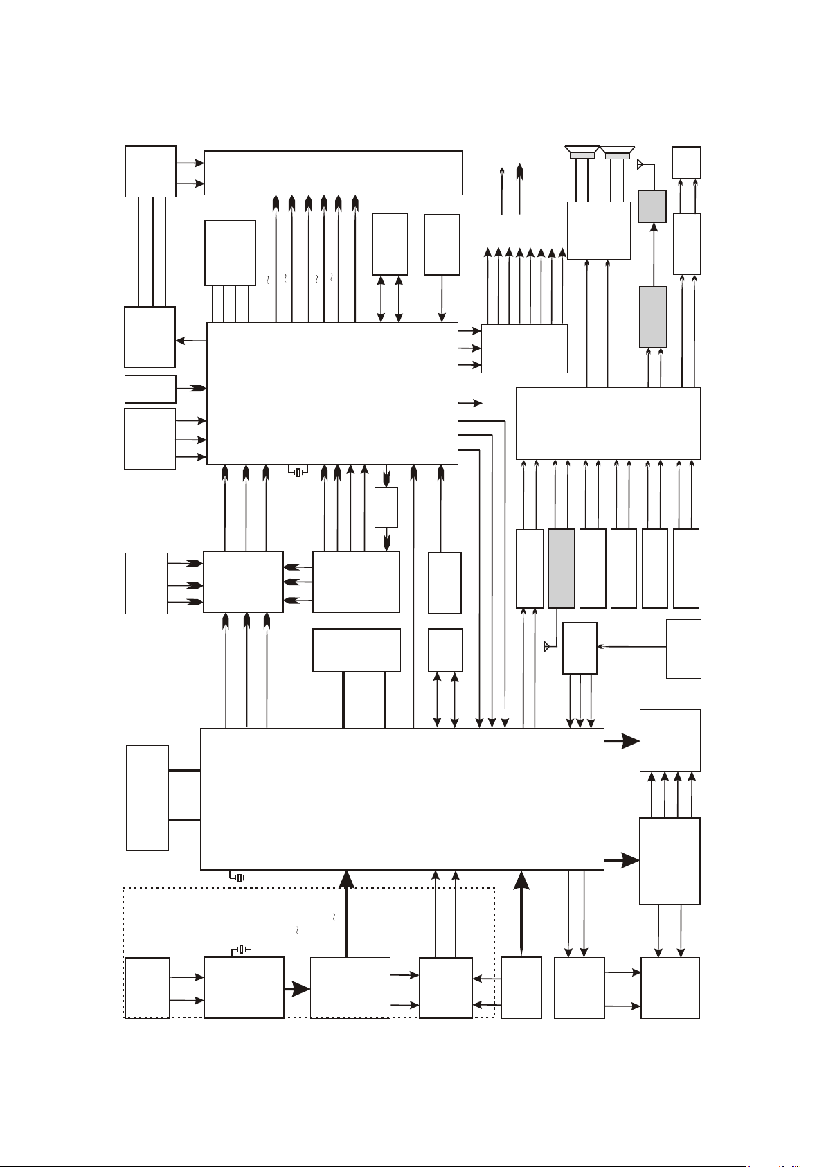
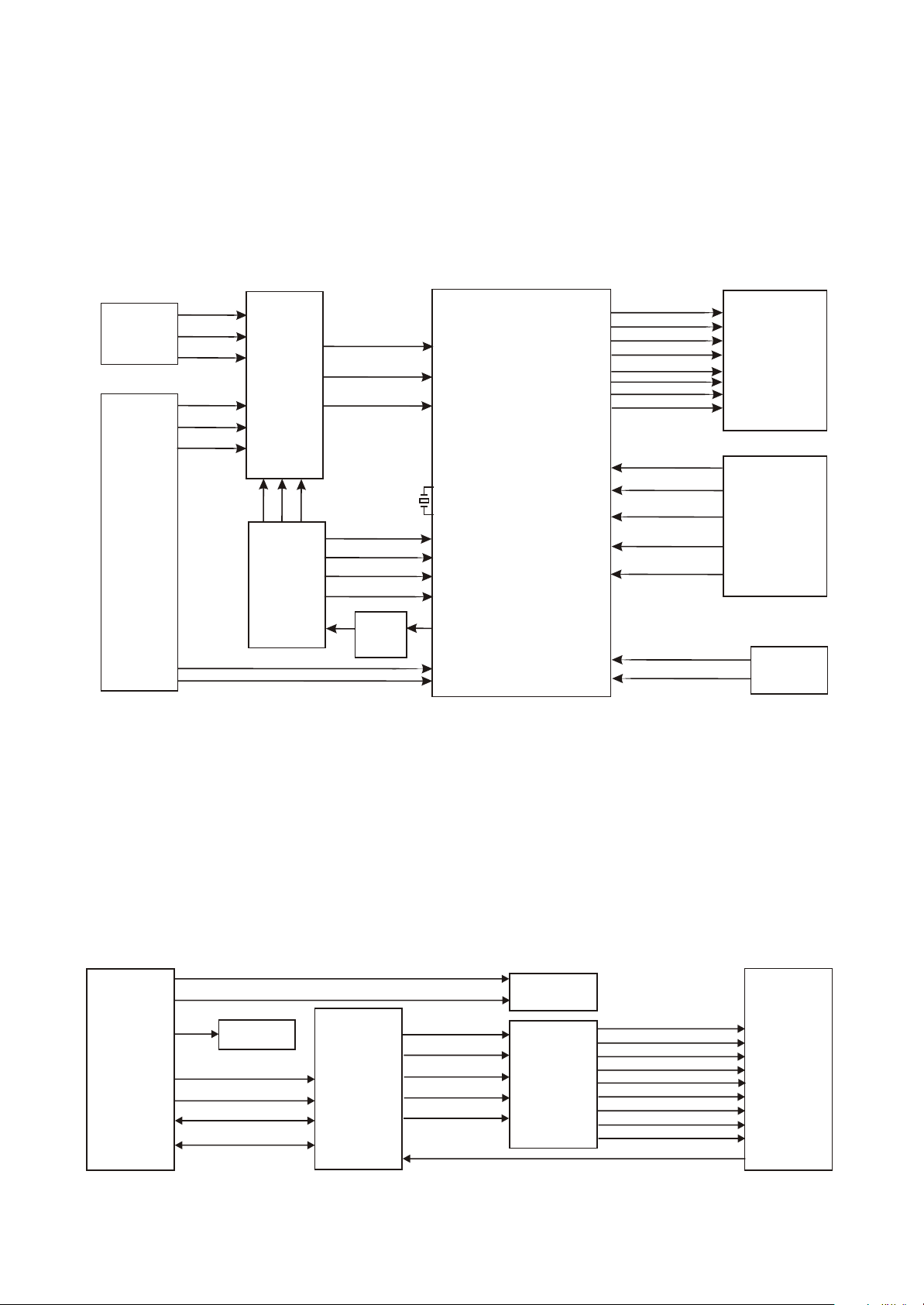
3.1.3 Block diagram of the player
- 19 -
BOARD
INVERTER
U104 FLASH
BLON
Brigtness
+12V
PS25LV010
LVA0 P LVA3P
SPICZ
SPIDI
SPICK
SPIDO
INVERTER_ON/OFF
Control circuit
of boost
voltageboard
JACK
VGA
IR
KEY1
KEY2
Button board
& receiving
board of RC
7/8
9/10
12/13
Y
PBIN
PRIN
EPR
EPB
U106
EY
FSAV433
Video
electronic
switch
YPBPR
INPUT
JACK J105
PANEL
U103
LVBCKP LVBCKM
LVB0P L VB3P
LVA0 M LVA3M
U101
X101
LVB0M L VB3M
LVACKP LVACKM
MST718
LCD picture
processor&MCU
67
24
25
66
12MHZ
SDARX
Video
SCLTX
SCVBS+
SCVBS-
SCART
JACK
SR SGSB
SCART
RF_OUT
1
2
14
VIDEO
AUDIO
21901-4
24C32
EEPROM
Reset circuit
Q103 Ce101
STBY1
8216_RST
FMUTE
ASW
ONMUTE
MUTE
VS1
MST_RESET
3
VSCK
2
VSDA
T4094
74
U102
1
PANEL ON
VS2
CD4094
83
73
34
amplify
30/31
22/23
63
DRIN
DLIN
FMR
FML
TV+/TV-
24
23
U117
DVSCK
DVSDA
DVSTB
U114
TUNER
U113
TEA5764
MC4580Audio
amplifying circuit
15
RF
Amplify
U112
Audio
amplify
TDA7266
4
12
Audio output
amplifying
RF_OUTPUT
LSL
LSR
BU1418
FLIN
circuit
FM Modulate
AO2L
AO2R
FRIN
U4
STV8317
NICAM
processing
circuit
AVRIN
PCLIN
J103
PC AUDIO
SRIN
MONOIN
U114
TUNER
SIOMAD
PCRIN
AVLIN
SLIN
J105
SCART JACK
A/V input terminal
DCVBSIN+/DCVBS-
U303
U301
SDRAM
DY
DPB
DPR
DDQ[0:15]
U302
DVD
FLASH
U115
DMA[0:11]
Mt1389
24C16
EEPROM
DSDA
DSCL
89AL
226
100
98
109
U5
CS5340A/D
89AR
Convertion
ABCK
ALRCK
AMDATA
224
OKA
MIC
BOARD
61506-2
DVD
PICK_UP
A/B/C
D/E/F
FC-
FC+
TK+
TK-
DFA[0:20] DFD[0:7]
X109
DVB Part
If1
If2
TUNER
U119
27MHZ
X602
20.48MHZ
PN2020
XIDD0 XIDD15
TSDATA0 TSDATA7
U116
MT8606
DVD decode chip
GPIO_4
GPIO_3
XIDD0
XIDD8
DVB/CARD
Conversion
MSD1
MSD0
CRAD
switch
U108/U2
BOARD
54
39
FOSO
TRSO
FMSO
TROPEN
TRCLOSE
U118
BA5954
Servo driving
DMSO
SL+
SL-
LOAD+
LOAD-
open/close
Tray
circuit
DVDLOAD
figure 3.1.3.1 Block diagram of the player
3.1.4 Audio circuit
- 20 -
Audio processing circuit is mainly responsible for the switch, amplifying and restire of audio and
composed of audio source input selection and NICAM processing circuit, audio amplifying circuit and
mute control circuit. Audio processing circuit block diagram is shown in the figure 3.1.4.1:
MT1389
ALRCK
ABCK
AMDATA
U5
CS5340A/D
conversion
OKA
MIC
BOARD
61506-2
89AL
226
89AR
224
PC AUDIO
J103
U114
TUNER
SCART JACK
J105
A/V input terminal
U117
MC4580Audio
amplify circuit
Figure 3.1.4.1 Audio processing circuit block diagram
DLIN
DRIN
PCLIN
PCRIN
SIOMAD
MONOIN
SLIN
SRIN
AVLIN
AVRIN
28
29
13
U4
14
STV8317
NICAM
92
98
processing
circuit
9
10
19
20
34
36
17
18
LSL
LSR
AO2L
AO2R
U112
4
TDA7266
Audio
12
amplifying
Audio output
Amplifying
circuit
1
2
15
14
3.1.5 Power circuit
Power circuit supplies stable and pure power for each unit circuit to ensure normal working of the
player. Power circuit block diagram is shown in the figure 3.1.5.1:
AMPRIN+
AMPLIN+
AMPROUT+
SCART
61506-2
AMPLOUT+
IC 503
AP1506
U511
+12V
Power adapter
Standby
control circuit
AP1506
U506
INVERTER
BOARD
U502
Si9435
Figure 3.1.5.1 Power circuit block diagram
+5VEXT
+12V
STBY
5V
U505
AMS1117
U507
Lm1085
MST718
U513
U1
AMS1117
U521
Lm1085
FOR PANEL
3.3V
+2.5V
MST718
+3.3V
1.8V
Dv33
3.1.6 Video circuit
- 21 -
Video circuit is mainly responsible for the input of external video signals, the processing of video
signals send from tuner, and the drive processing of LCD screen, including video input selection, video
A/D conversion circuit, LCD picture processing circuit and video output circuit. Video circuit block
diagram is shown in the figure 3.1.6.1:
Y PB PR
INPUT
JACK
185
183
182
Mt1389
187
EY
EPB
EPR
U106
Video
DY
Electronic
switch
DPB
DPR
FSAV433
SR
DCVBSIN+/DCVBS-
SG
SB
SCART
JACK
13
15
17
PRIN
PBIN
Y
X101
12MHZ
SCVBS+
SCVBS-
SCLTX
SDARX
Video
amplifying
7/8
9/10
12/13
U101
MST718LCD picture
processor&MCU
24
25
67
66
34
22/23
30/31
LVA0~3P
LVA0~3M
LVB0~3P
LVB0~3M
LVACKP
LVACKM
LVBCKP
LVBCKM
BIN+ BIN-
GIN+ GIN-
RIN+ RIN-
VGA-VSYN
VGA-HSYN
TV+/TV-
PANEL
VGA JACK
TUNER
Figure 3.1.6.1 Video circuit block diagram
3.1.7Block diagram of DVB is shown in figure3.1.7.1:
1.LD1506DK machine consists DVB function and can demodulate DVB-T signal.LD1506DK
does not consist this circuit.DVB part of this machine adopts PN2020AT+MT8606 and other
elements. Block diagram of DVB part is shown as follows:
STV8317
XIDD0~XIDD15
XIDA0~XIDA2
0689_CLK
8606_RST
XIIORDY
ASDFAT0
XIINTRO
XIDIOW
SIDIOR
MT1389
Aideo/Video
Decoder
U114
TUNER
TV+
MST718BU
TV-
IF1
IF2
TUNSDA_D1
TUNSCL_D1
TSDATA0~TSDATA7
TSVALID
TSSTRT
U119
PN202AT
Figure 3.1.7.1 DVB circuit block diagram
TSCLK
TSFALL/RESET
MT8606
Transport
stream
Receiver
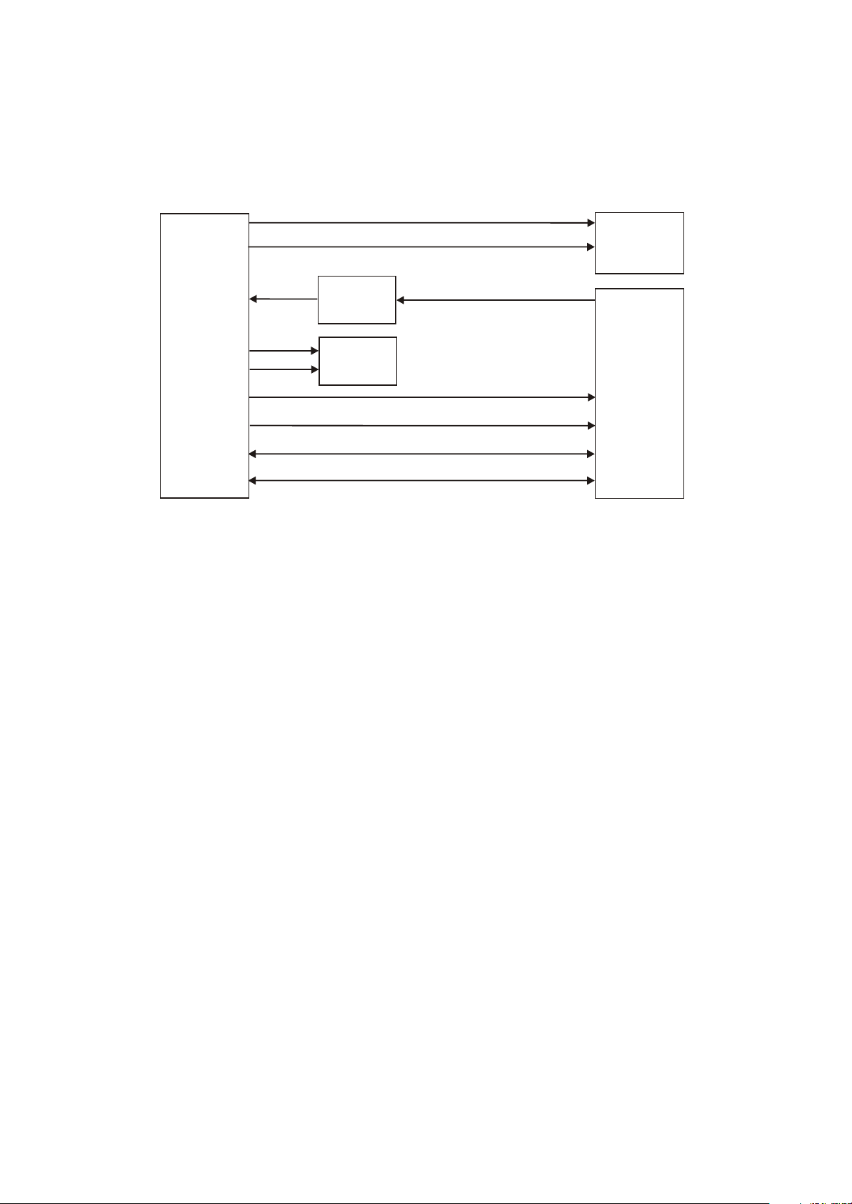
2.Block diagram of DVB receiving circuit is shown in igure 3.1.7.2:
- 22 -
NONIN
TUNER
IF_GAIN
TV+
TV-
SIOMAD
AGG
Feedback
Cirduit
MST718BU
IF1
IF2
TUNSDA_D1
TUNSCL_D1
STV8317F
PN2020AT
Section Two Troubleshooting flow chart
- 23 -
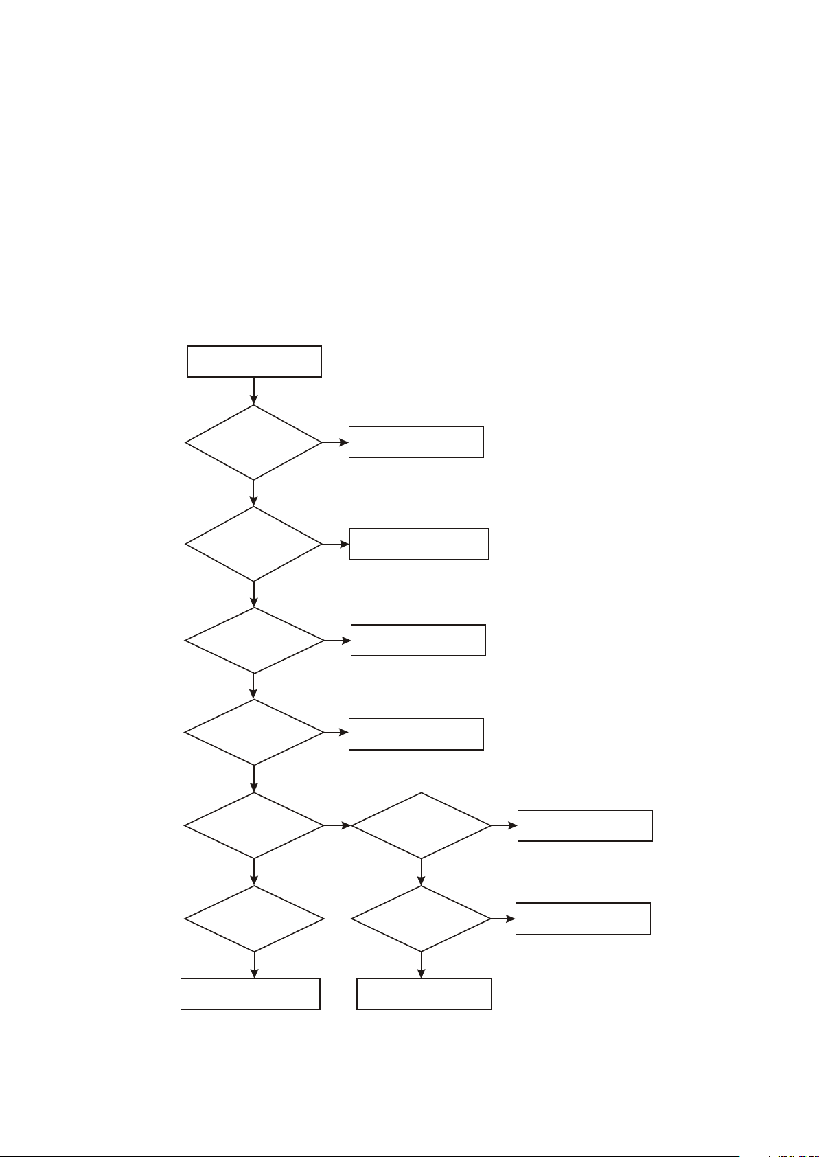
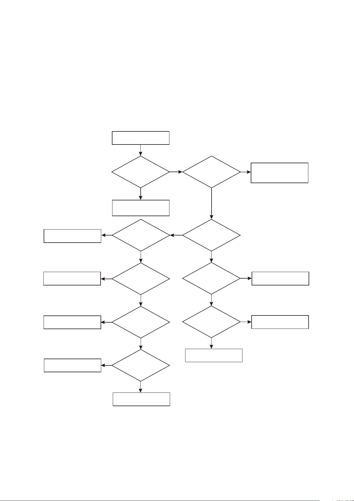
[ Flow chart 1 ] Trouble symptom: standby light is not on
Trouble description: connect with power, standby indicator light is not on, machine has no response
and buttons have no function.
Machine not power on
Whether
12V voltage
outputted by power
adapter is
normal
Y
Check
whether J501 pin 2
12Vvoltage is
normal
Y
Check
whether U503 pin 2
5V voltage is
normal
Y
Check
the power supply
loop from +5VEXT power
toMST718 is
normal
Y
Check
whether standby
control signal outputted
by MST718_57 is
normal
N
Check power adapter
N
Check flat cable from power
adapter to video main board
N
N
N
Change U503
Check power supply loop
Check
whether reset
signal of MST718
is normal
N
Check reset system circuit
Y
Check
whether Q117 is
normal
Y
Check the standby indication
circuit on subsidiary board
Y
Check
whether X101 clock
signal is normal
Y
Change MST718
N
Check clock system circuit
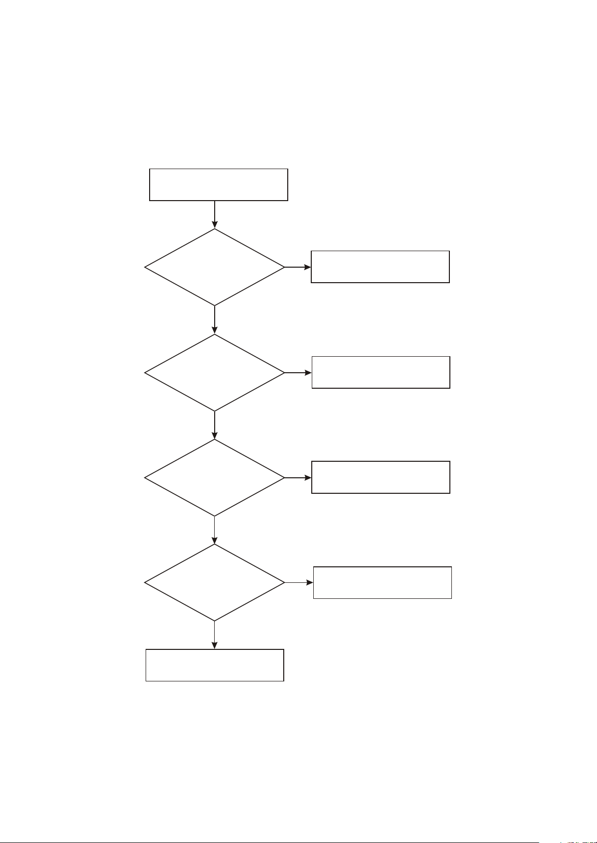
[ Flow chart 2 ] Symptom: power not on
- 24 -
Trouble description: test after machine power on, standby indicator light is not on and +12V power
outputted by power adapter is abnormal.
Power not on
Check fuse, TC1 and
rectifying bridge
Check NCP1207 and
peripheral elements
Change Q1
Check
whether power
board Cn2
has 12V voltage
Y
Check according to
troubleshooting process
for“player not switch on”
N
Check
whether power
board TC1 has 310v
voltage
Y
N
Check
whether each pin
voltage of U1 is
normal
Y
N
Check
whether Q1 is
damaged
Y
N
Check
whether 12v
resistor to ground
is normal
Check whether filtering
N
capacitor TC3/TC4 has
electric leakage and
short-circuit
Y
N
Check
whether VD4
has secondary
voltage
Y
Check
whether VD4
secondary voltage is
normal
N
Check feedback loop
U2/U3
Y
Check
whether voltage
of TC2 two ends
is normal
N
Change L3
Y
Change transformer
N
whether transformer
is normal
Check VD4
Check
END
Y
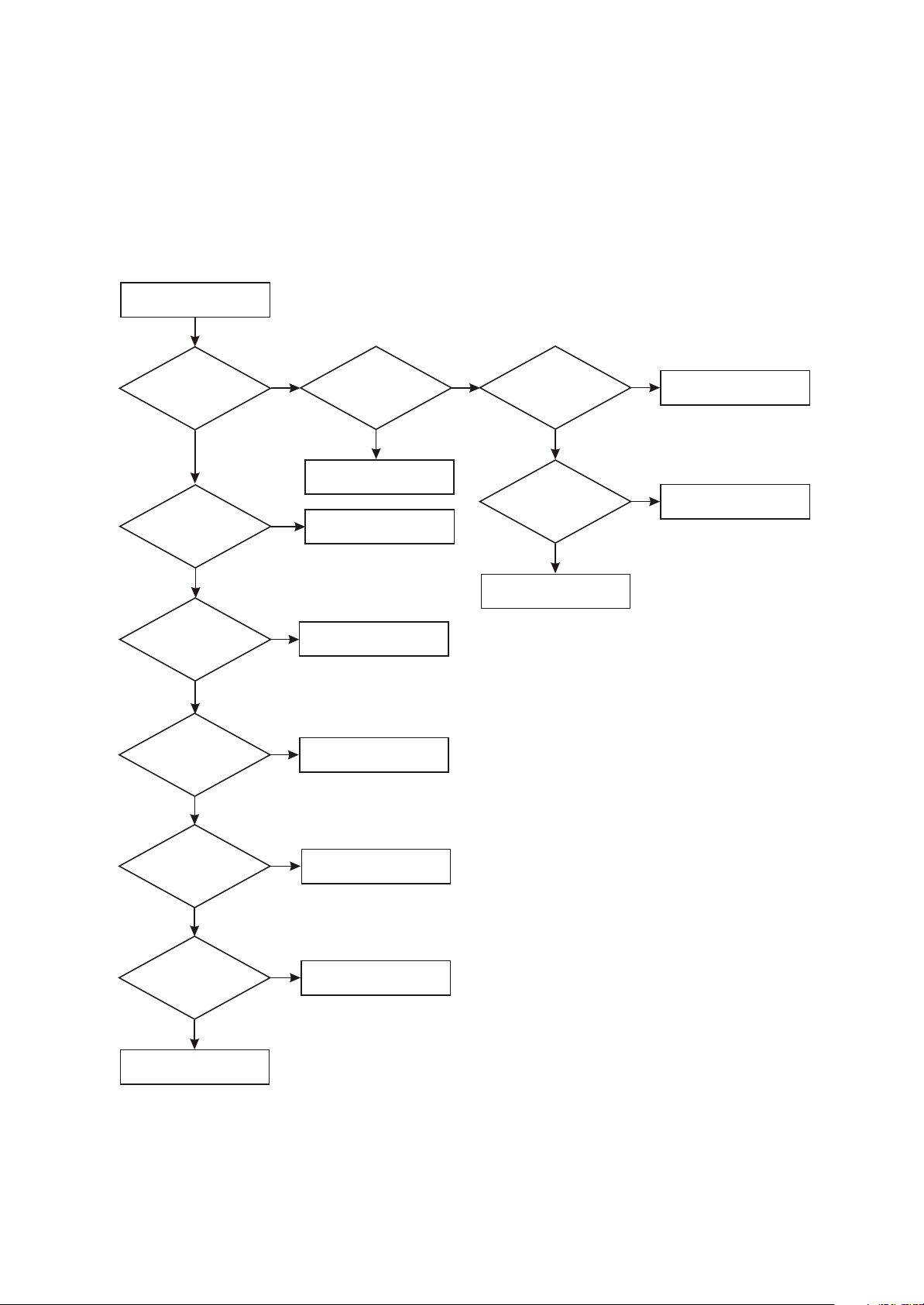
[ Flow chart 3 ] Symptom: no sound
- 25 -
Description: there is image, but no audio output.
All input source has
no sound output
Y
Check
whether pin 34/36
of STV_8317 has signal
output
Y
Check
whether power
supply of power amplifier
board TDA7266 is
normal
N
N
Check STV8317 and
peripheral elements
Check power supply loop
of TDA7266
Y
Check
whether TDA7266_6
pin is high level
Y
Check
whether audio output
pin waveform of
TDA7266P is
normal
Y
Check speaker and line
N
Check mute control circuit
N
Change TDA7266P
[ Flow chart 4 ] Symptom: white screen
- 26 -
Description: screen is white and indicator on.
White screen
Check
whether u502_D
voltage is normal
Y
Check
whether 2.5V
voltage of pin 2 of
U507 is normal
Y
Check
whether 3.3V
voltage outputted
by U505 is
normal
Y
Check
whether X101 clock
is normal
Y
N
whether u502_G pin is
Change U502
N
N
Change U507
Change U505
N
Check X101/C103/C104
Check
low level
Y
N
Check Q504 and peripheral
elements
Check
whether U15_37
(PANEL_ON) is low
level
Check
whether Q505_C is
high level
N
Change MST718
Y
N
Check Q505 and peripheral
elements
Y
Check
whether drive
output pin MST718
outputs normally
Y
Check
whether the socket
and flat cable from main
board to display screen
are normal
Y
Change display screen
N
Change MST718
N
Change flat cable or socket
 Loading...