


L2M18 Product Specifications
LCD TV control board specification for L2M18 with 9E19/9U19 chipset

CONTENTS
No. Items
1 General description
2 Transport/storage/operation description
3 Features
4 Block diagram
5 Preset mode for VGA/YPbPr inputs
6 Interface arrangement
7 Interface definition and pin function
8 Schematic diagram
9 PCB Layout and dimension
10 Software upgrade
11 Service mode description
1, General description
L2M18 is a control board of Color Active Matrix Liquid Crystal Display, It is designed to be
applied to LVDS(Low Voltage Differential Signaling)as the interface method to enable a simple
and low-cost implementation in both board and panel.
L2M18 is intended to support YPbPr&HDMI input and up to 1920x1080 FHD panel.
L2M18 also provides other very important functions, It supports PAL or SECAM color TV system
for Europe, Moreover. it can achieve Analog RGB input signal up to SXGA 1024 vertical /1280
horizontal pixel resolution. it also supports DVD(Option)/YPbPr /HDMI input.
L2M18 includes an audio amplifier which can support 2×3W(or 2x5W) audio power output. it
supports NICAM/A2 stereo input and selects audio channels according to the input signal
detection. OSD pictures are smooth and manual operating is very simple.
Notes:
Different between 9E19 and 9U19.9E19 with Teletext,9U19 without Teletext.
2, Transport/storage/operation description
★ Must not be pressed and distorted
★ Keep away from static places and water
★ Relative Humidity: ≤80%
★ Storage Temperature: -10~+60℃
★ Operation Temperature: 0~+40℃
3,Features
Below you will find the detailed features
SYSTEM PAL BG/DK/I, SECAM BG/DK/L/L’
TV
Frequency Band 48.25 MHz—863.25MHz
Input Level 1.0Vp-p +/- 10%
CVBS
Format PAL, NTSC, SECAM
Format DOS,VGA, SVGA,XGA,SXGA
Color 24BIT
Analog RGB
Input signal
H-Frequency 30—80KHz
V-Frequency 56—5Hz
YPbPr(YCbCr) Format 480i,576i,1080i,480p,576p,720p,1080P
HDMI Format 480i,576i,1080i,480p,576p,720p,1080P
YPbPr+L/R signal Input
DVD(option)
SPI protocol
Interface
Audio Input
Level
Input
Output
≤2V rms.
TV IEC socket
Analog RGB D-SUB 15 jack
YPbPr/YCbCr Green/Blue/Red RCA jack
PC audio Φ3.5mm headphone jack
SCART 1xFull SCART
HDMI x1
16Pin 1.0mm patch FFC +5 pin 2.0mm
DVD(Option)
patch power in+6 pin 2.0mm patch YPbPr
jack
To panel LVDS:30Pin 2.0mm patch jack
Φ3.5mm headphone jack
Audio
Speaker:4Pin 2.54mm patch Jack
Power
Other
Power Input DC in 12±2V
Panel voltage 3.3V, 5V, 12V
Standby Mode
<1W (main board need 12V 35mA for standby mode)
TDA7266
≥2×5W (8Ω)
Amplifier
Remote and key 5 pin 2.0mm patch jack
Key 3 pin 2.0mm patch jack
Inverter 6 pin 2.0mm patch jack
Key definition VOL-,VOL+,CH+,CH-,MENU,TV/AV,POWER
OSD language 26 countries OSD language
Comb filter 3D
De-interlace 2D
Teletext 200pages
Compatibility of
DVD-R/DVD-RW/DVD+R/DVD+RW/CD-R/CD+R
Disc
Digital Video
DVD-Video/Divx/Xvid/SVCD/VCD
Playback
DVD unit
(option)
Digital Audio
CD-DA/HDCD/MP3/WMA
Playback
Digital Graphic
Kodak Picture CD/ JPEG
Playback
Dolyb & DTS Decoding ,Children Lock for inappropriate
Others
Discs
1:MPEG-1 ML/MP conforming to ISO-11172
Digital Video
2:MPEG-2 ML/MP conforming to ISO-13818
Card Reader
and USB
Section
(option)
Format
3:MPEG-4 and Divx 3.x/4.x/5.x compliant
1:Full MPEG Audio Layer I/II and III(MP3)
digital Audio
2:Flexibity to Dolby AC-3 5.1 Channel or 2 Channel
format
Down-mixing,HDCD,MP3 and WMA
Supported card SD/MS/MMC Media Card
Notes:
Supported OSD language:
Arabian/Spanish/Portuguese/Swedish/German/French/Russian/Italian/Danish/Finnish/Greek/
Norwegian/Dutch/Polish/Turkish/Lithuanian/Serbian/Chinese/Romanian/Blugarian/Lettish/Estoni
an
Hungarian/Slovenian/Slovakian/Czech
L2M18 chassis only can support 8 countries OSD language caused by the flash rom size
limitation. Please indicate which OSD language you needed when you place purchase order.
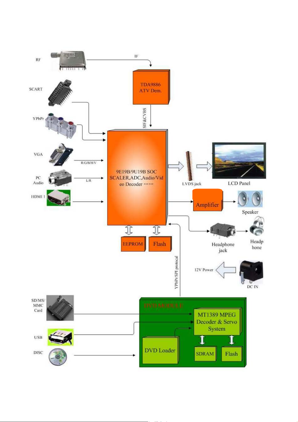
4,Block diagram
TDA7266
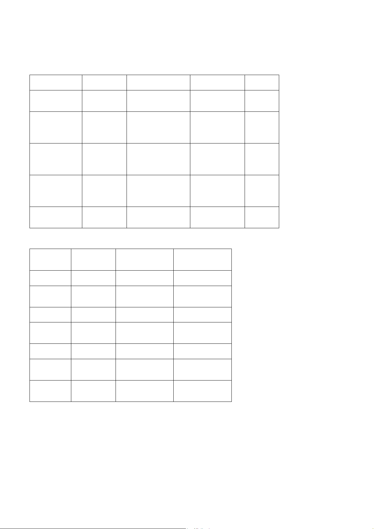
5,Preset mode for VGA/YPbPr inputs
Below the preset mode for VGA,YPbPr (pixel format, H-Frequency and V-Frequency)
★Analog RGB format table
Pixel Format Resolution Horiz.Freq.(KHz) Vert.Freq.(Hz) Standard
SXGA 1280×1024
XGA 1024×768
SVGA 800×600
VGA 640×480
640×480
DOS
720×400
★YPbPr format table
Format Resolution
63.5
80
48.4
56.5
60.0
37.9
47.2
46.9
31.5
37.5
37.9
31.5
31.5
Horiz.Freq(KK
z)
60
75
60
70
75
60
72
75
67
75
72
60
70
Vert. Freq. (Hz)
VESA
VESA
VESA
VESA
VESA
576i 576 15.63 50.00
59.94
480i 480 15.73
60.00
576p 576 31.26 50.00
59.94
480p 480 31.47
60.00
1080i/50 1080 28.13 50.00
59.94
1080i/60 1080 33.75
60.00
59.94
720p/60 720 44.96
60.00
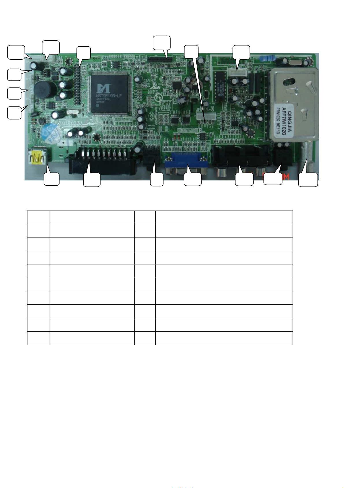
6,Interface arrangement
11
12
13
14
16
10
9
15
8
1
2 3
4 5
★ INTERFACE FUNCTION DESCRIPTION
NO Description NO Description
1 HDMI Input 10 LVDS Interface
2 SCART 11 Key Jack
3 PC/YpbPr Audio Input 12 DVD power supply jack
4 VGA Input 13 IR Jack
5 YPbPr Input 14 Inverter Jack
6 Headphone output 15 DVD YPbPr jack
7 RF Input 16 Inside power supply jack(small size)
8 Speaker Jack 17
9 DVD FPC Interface 18
6
7

7,interface deninition and pin function
★J9: Inverter jack
NO. Definition Description
1 12v Power Supply
2 12v Power Supply
3 BLO
Black-Light ON/OFF
Control
4 Bri Brightness Adjustment
5 GND Ground
6 GND Ground
★CON16: Speaker jack
NO. Definition Description
1 L Left Speaker Output
2 GND GND
3 GND GND
4 R Right Speaker Output
★ CN104: Key jack
NO. Definition Description
1 K1 Key 1 (ADC Input)
2 GND GND
3 K2 Key 2 (ADC Input)
★J16: DVD YPbPr jack
NO. Definition Description
1 GND GND
2 Y DVD Signal Y
3 GND GND
4 Pb DVD Signal Pb
5 GND GND
6 Pr DVD Signal Pr

★CN5: DVD FFC INTERFACE
NO. Definition Description
1 KEY2 KEY2(ADC Input)
2 DRIN
Right Channel of DVD
Audio Input
3 KEY1 KEY1(ADC Input)
Left Channel of DVD Audio
4 DLIN
Input
5 12V 12V input
6 NC
7 GND GND
8 NC
9 GND GND
10 NC
11 NC
12 GND GND
SPI Communication
13 SDA
Protocol SDA
SPI Communication
14 SCK
Protocol SCL
SPI Communication
15 STB
Protocol STB
16 GND GND
★J1: DVD Power jack
NO. Definition Description
1 5V DVD 5V Power Supply
2 5V DVD 5V Power Supply
3 GND GND
4 GND GND
5 GND GND

★CN6: IR&LED jack
NO. Definition Description
1 GND GND
2 IR Remote Receiver
3 LED-G Green Indicator
4 LED-R Red Indicator
5 5V Power Supply
★CN7: Internal power supply jack for small size TV
NO. Definition Description
1 12v Internal 12V Power Supply
2 12v Internal 12V Power Supply
3 GND GND
4 GND GND
★J3: Internal power supply jack for big size TV
NO. Definition Description
1 12v Switchable 12V Supply
2 SW 5v Switchable 5V Supply
3 SW 5v Switchable 5V Supply
4 GND GND
5 GND GND
6 GND GND
7 Stdby Standby on/off
8 Stdby 5V Standby 5V
9 GND GND

★CN6: LVDS Interface
NO. Definition Description
1 LCD-VDD Power for Panel
2 LCD-VDD Power for Panel
3 LCD-VDD Power for Panel
4 NC NO Connect
5 GND GND
6 GND GND
7 GND GND
8 GND GND
9 EDA3+ LVDS EVEN3+ Signal
10 EDA3- LVDS EVEN3+ Signal
11 ECK+ LVDS EVEN Clock + Signal
12 ECK- LVDS EVEN Clock - Signal
13 EDA2+ LVDS EVEN2 + Signal
14 EDA2- LVDS EVEN2 - Signal
15 EDA1+ LVDS EVEN1 + Signal
16 EDA1- LVDS EVEN1 - Signal
17 EDA0+ LVDS EVEN0 + Signal
18 EDA0- LVDS EVEN0 - Signal
19 GND GND
20 GND GND
21 ODA3+ LVDS ODD3 + Signal
22 ODA3- LVDS ODD3 + Signal
23 OCK+ LVDS ODD Clock + Signal
24 OCK- LVDS ODD Clock - Signal
25 ODA2+ LVDS ODD2 + Signal
26 ODA2- LVDS ODD2 - Signal
27 ODA1+ LVDS ODD1 + Signal
28 ODA1- LVDS ODD1 - Signal
29 ODA0+ LVDS ODD0 + Signal
30 ODA0- LVDS ODD0 - Signal

8, Schematic diagram


9,PCB layout and dimension


Remark: LD1913SU and LD2213SU don’t have DC in.
10,Software upgrade
1)Open the update tools--Mstar ISP Utility

2)Click “Device” button and double click select correctly type(For MST9E19 chassis select
Pm25LV040 normally)
3)Click “Config” button and click “Auto Detect” button confirm that the PC and ISP tool connect
properly. adjust the LPT port speed to 138K,in order to speed up update process.
4)Click “Read” button then select the binary file of firmware.

5)Click “Auto” button and remove the marker of “Blank” and “Verify” items. then click “Run”, after
several seconds the update process will be finish.
11,Service mode description
1) How to enter service mode
Press “Source” button on the remote control, then press”2580”, the service menu will be
displayed as below.
2580
Source

2) Service mode description
Color Temp: select a color temperature mode that you want to adjust;
R Gain: red gain for white balance adjusting;
G Gain: green gain for white balance adjusting;
B Gain: blue gain for white balance adjusting;
R Offset: red offset for white balance adjusting ;
G Gain: green offset for white balance adjusting;
B Gain: blue offset for white balance adjusting;
Aging: to turn on or off aging mode, optional setting: On Off;
Auto config: auto adjust ADC channel difference, only available in VGA mode;
EEprom clear: reset EEPROM data to default value, all user’s program and setting will be
lost;
Panel: select different panel for factory;
TTX language: select Teletext language, optional setting: West East Russia;
DVD source set: to turn on or off DVD source in the user menu, optional setting: On Off;
Hotel mode: to turn on or off hotel mode, optional setting: On Off;
Key mode:to turn on or off local keyboard, optional setting: On Off;
Power on: to setting the power on source, optional setting: TV Other;
Power mode: to setting the power on mode, optional setting: Force on Memory standby;
Volume:to setting the max sound volume when hotel mode is active;
AGC: to setting tuner’s RF AGC value;
Notes:
1,color temperature adjusting:in different source the white balance can be adjust
separated.the details as below:
1)DVD&YpbPr source use same group color temperature value.
2)TV&Scart source use same group color temperature value.
3)VGA&HDMI source use separated color temperature value.
2,Auto Config:please change source to VGA mode and with grey scale pattern then
enter service mode to do this item.
 Loading...