

Page 1

FSW-108
SERVICE MANUAL
Page 2

CONTENT
CHAPTER 1(ACOUSTIC)
SPECIFICATIONS-------------------------------------------------------------------3
PRECAUTIONS----------------------------------------------------------------------3
GENERAL CHART-------------------------------------------------------------------4
BILL OF MATERIAL-----------------------------------------------------------------4
CHAPTER 2(ELECTRONIC)
SPECIFICATION---------------------------------------------------------------------6
DISASSEMBLY INSTRUCTION---------------------------------------------------7
CIRCUITRY PRINCIPLE CHART--------------------------------------------------9
PROCESS CHART-------------------------------------------------------------------10
PCB BOARD-------------------------------------------------------------------------11
GENERAL ASSEMBLY ILLUSTRATION----------------------------------------12
BILL OF MATERIAL---------------------------------------------------------------13
Page 1
Page 3

Chapter 1
(Acoustic)
Page 2
Page 4

SPECIFICATIONS
Model Number
Cabinet Type
Component
Speaker System
Speaker Terminals
Dimensions
(WxDxH)mm
Weight(net)
PRECAUTIONS
FSW-108
Subwoofer
100 woofer
Bass Reflex
Spring Clip
305x395x470
15.5 kg/pc
There are wires connected speaker with amplifier panel, when disassembling speaker, remember to unplug
the connecting terminals.
When disassembling amplifier panel, please refer to Chapter 2 (Electronic).
Page 3
Page 5
GENERAL CHART
Bill of Material
Page 4
Page 6

Chapter 2
(Electronic)
Page 5
Page 7

Amplifier main set
Output
Distortion factor
Page 8

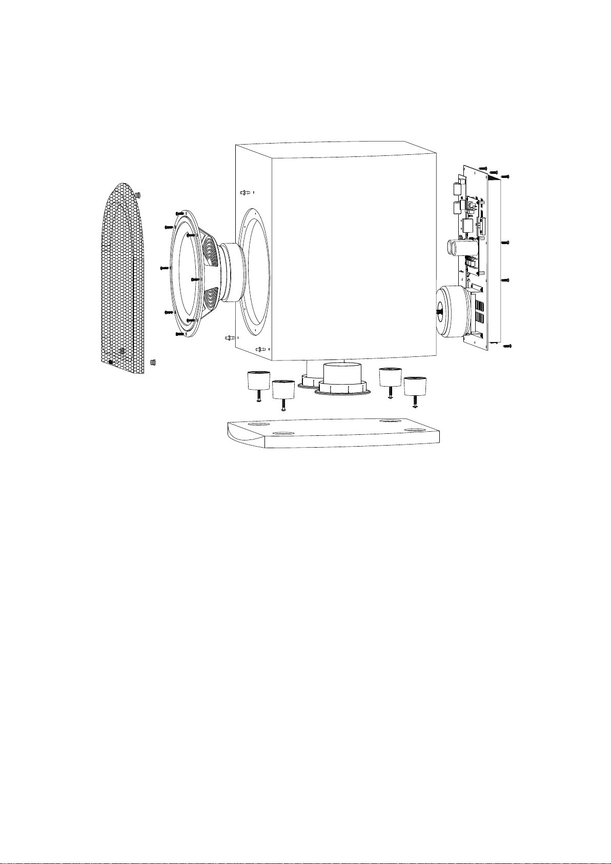
DISASSEMBLY INSTRUCTION
Please study the circuitry position well before any disassembly to ensure all
wires locate as original.
Rear panel
- Take away the 11 pcs screw A (fig.1);
- Move off the rear panel;
- Pull down the speaker terminal;
- Move off the rear panel.
A
F
G
F
Fig.1
Page 7
Page 9

C
B
E
D
E
C
Fig.2
Amplifier board
- Take away the 9 pcs screw B (fig.2);
- Pull down the speaker terminal C;
- Move off the amplifier board.
Front panel
- Take away the 1 pc screw D (fig.2);
- Take away the 7 pcs screw F (fig.1);
- Pull out the knob and disassembly the 2 nuts G under it (fig.1);
- Move off the front panel.
Page 8
Page 10

CIRCUITRY PRINCIPLE CHART
T6.3AL250
R10
C13
R8
101
D11
R9
LED1
2.2K
12K
R7
2K7
6
SW1
FUSE
T3.15A
C9
2
10K
IN4148
33u/25V
5
U1B
7
RG1
1 2
10u
U1A
1
471
C8
4558
332
3 4
C28223
3
4558
C201
R12
100K
C209
DW208
D210
75K
R235 10K
R223
5V6
4148
BR1T85
C212104
10K
2K2
22K
220K
U4A
U5A
U6A
R233
U5B
R225
C210
R224
R224
4558
U6B
4558
8K2
R230
WR202.AB
8K2
R229
4558
270
R227
4558
4558
0
B20K
10K
R234
684C211 334
WR201
B20K
471
C22
5V6
DW213
4148
D214
4L2
4L1
R16
33K
104
R228
4K7
C213
10K
R226
101
38mH
38mH
R232
SW201
27K
C100
C208
4R1
1M8/0.5W
27K
R23
1
PHASE
10u/16V
R208
R237
2K2
15K
0
8
6
4
1
K
R22
47K
R21
33K
27K
4C1
0.22U/AC275V
(+12V)
+B2
1K
R247
R245
R242
C1815
330K
C1
R21
R21
R13
2K2
R248
10K
10K
Q201
R240
R239
C225
R23810K
10u/16V
220K
R206
10K
Q202
1K
471
A1015
D203
4148
5V6
DW205
IN+
R203
390/3W
9
220K
R205
3
1
K
R217
R2072K2
N
O
6
4
K
R202
R21
1
D204
K
0
IN-
B1
4148
O
1
OFF
1
1
R24
10K
R24
U7A
100/2W
47K
471
LED3
AUT
R24
R24
4558
C219
34V*2
IN+
R204
C207
14V*2 12V
Sw202
390/3W
101
5V6
4148
V
F
3
V
F
2
V
1
R18
R17
AUTOSTANDBY
IN-
R201
100/2W
4558
DW207
D209
F
2.2
2.2
LED2
T6.3AL250
T1AL250
Q9
R251
4558
V
C7
C6
U4B
DW211
4148
C12
C3
C17
C16
5551
3K3
U7B
C21
5
2M7
R24
9
220u/50V
220u/50V
R215
R213
5V6
D212
D5
FS6A10
D3
C18
FS6A10
6800u/63V
C5
C19
6800u/63V
2200U/25V
3
1
2200U/25V
Q1
8050
5V6
Q8
Q7
C2
220u/25V
2SC3858
Q11
Q5
100P
C54
Q18
Q21
C4
U2
Vin
Vin
U3
Q3
A1015
C15
Q2
R53
1K5
2N5551
2N5551
104
104
7912
V
GND
1
3
GND
V
7812
470u/16V
9014
R2
56K
R26
0.22\5W
R4
120\2W
10u/50V
104
104
D2
D4
FS6A10
FS6A10
C10
220u/25V
D1IN400
1
IN400
1
D
7
+B0
IN400
1
D
8
C20
C21
104
104
104
C22
104
D
9
D
6
IN400
1
C23
IN400
1
+B0
D12
IN4001
JK1
R1
22K
DW6
R3
10K
9015
9014
100U/16
+B1
2SC2073
200R59
R67
Q19
2N5401
2K2
R73
33K
2K2
R78
27K
C59
2K2
R75
103
C60
10u/50V
+B1 -B1
-12
+12
JK1
L1
C49
Q6
56k
LED1
220u/16V
2
220u/16V
2
1uH
R25
R5
2N5551
75
R66
75
R74
R250
2K2
C25
C24
R6
0.22\5W
120\2W
10/ 2W
D13
4148
2K2
R55
+B2 -B2
Q14
R77
D17
IN4001
2N5551
33K
R65
R72
200
D16
470
-B1
IN4001
R52
R63
R11
56K
100K
3K9
C55
100u/50V
C11
104
Q10
2SA1494
Q4
2SA940
2N5551
Q15
IN201.L
IN201.R
Page 9
Page 11

PROCESS CHART
AMPLIFIER
SIGNAL INPUT
POWER
Page 10
Page 12

GENERAL ASSEMBLY ILLUSTRATION
øÃ∂»
1.000
Page 12
Page 13

Page 14

PCB BOARD
Page 11
 Loading...