

Page 1

xKit Operation Manual
XKIT USER MANUAL
DFG MODULE INTRODUCTION
SERVOTEST
NOV/2025
Page 2

xKit Operation Manual
Contents
1 DFG Module Introduction .............................................................................................. 4
1.1 Function introduction .............................................................................................. 4
1.2 Main Interface ......................................................................................................... 4
2 DFG Basic Function ....................................................................................................... 4
2.1 Main Menu .............................................................................................................. 4
2.1.1 File .................................................................................................................... 4
2.1.2 Setting ............................................................................................................... 7
2.1.3 Generate ............................................................................................................ 7
2.1.4 Save Sef ............................................................................................................ 7
2.2 Function Switching .................................................................................................. 8
2.3 Parameter Setting Area ............................................................................................ 9
2.4 Drawing Function Area ......................................................................................... 10
2.4.1 Data Graph...................................................................................................... 10
2.4.2 Right-click Menu ............................................................................................ 10
2.5 Adjust Area Size .................................................................................................... 12
2.6 Supported Image Formats ...................................................................................... 12
2.7 Middle Scroll Wheel .............................................................................................. 12
2.7.1 Double Click ................................................................................................... 12
2.7.2 Scrolling of Middle Wheel ............................................................................. 13
3 DFG function introduction ........................................................................................... 13
3.1 PSD Module .......................................................................................................... 13
3.1.1 PSD Setting Area ............................................................................................ 14
3.1.2 PSD Formats ................................................................................................... 15
3.1.3 Other Features ................................................................................................ 15
3.2 FRS Module .......................................................................................................... 16
3.2.1 FRS Setting Area ............................................................................................ 17
3.2.2 Drawing Display Settings ............................................................................... 21
3.2.3 FRS Formats ................................................................................................... 21
3.2.4 Other Features ................................................................................................ 21
Page 3

xKit Operation Manual
3.3 Shock Module ........................................................................................................ 22
3.3.1 Shock Setting Area ......................................................................................... 22
3.3.2 Shock Formats ................................................................................................ 23
3.3.3 Other Features ................................................................................................ 23
3.4 Sweep Module ....................................................................................................... 24
3.4.1 Sweep Setting Area ........................................................................................ 25
3.4.2 Sweep Formats ............................................................................................... 26
3.4.3 Other Features ................................................................................................ 26
3.5 ASW Module ......................................................................................................... 26
3.5.1 ASW Introduction .......................................................................................... 27
3.5.2 ASW Setting Area .......................................................................................... 27
3.5.3 Other Features ................................................................................................ 28
3.6 MCG Module......................................................................................................... 29
3.6.1 Main Menu ..................................................................................................... 29
3.6.2 MCG Setting Area .......................................................................................... 30
3.6.3 Right-click Menu ............................................................................................ 33
3.6.4 Other Features ................................................................................................ 33
Page 4
xKit Operation Manual
1 DFG Module Introduction
1.1 Function introduction
DFG is an integration of the original Pulsar DFG 1.0 and 2.0. This module includes
six functional modules: PSD, FRS, Shock, Sweep, ASW, and MCG. Clicking the ‘DFG’
drop-down menu button on the left allows you to switch between these six functional
modules at will.
1.2 Main Interface
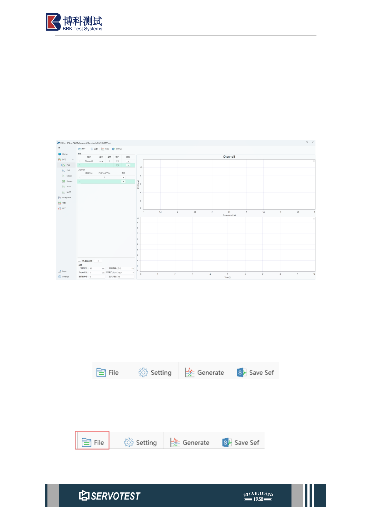
Figure 1-1 Main Interface
The main interface is as shown in the figure, including the upper menu bar, the
parameter input on the left and the drawing part on the right. Toggle functions on the
menu bar. The operation of the main interface of each function is similar.
2 DFG Basic Function
2.1 Main Menu
Figure 2-1 Main Menu
The main menu consists of four sections: File, Settings, Generate Data Graph, and
Save Sef File.
2.1.1 File
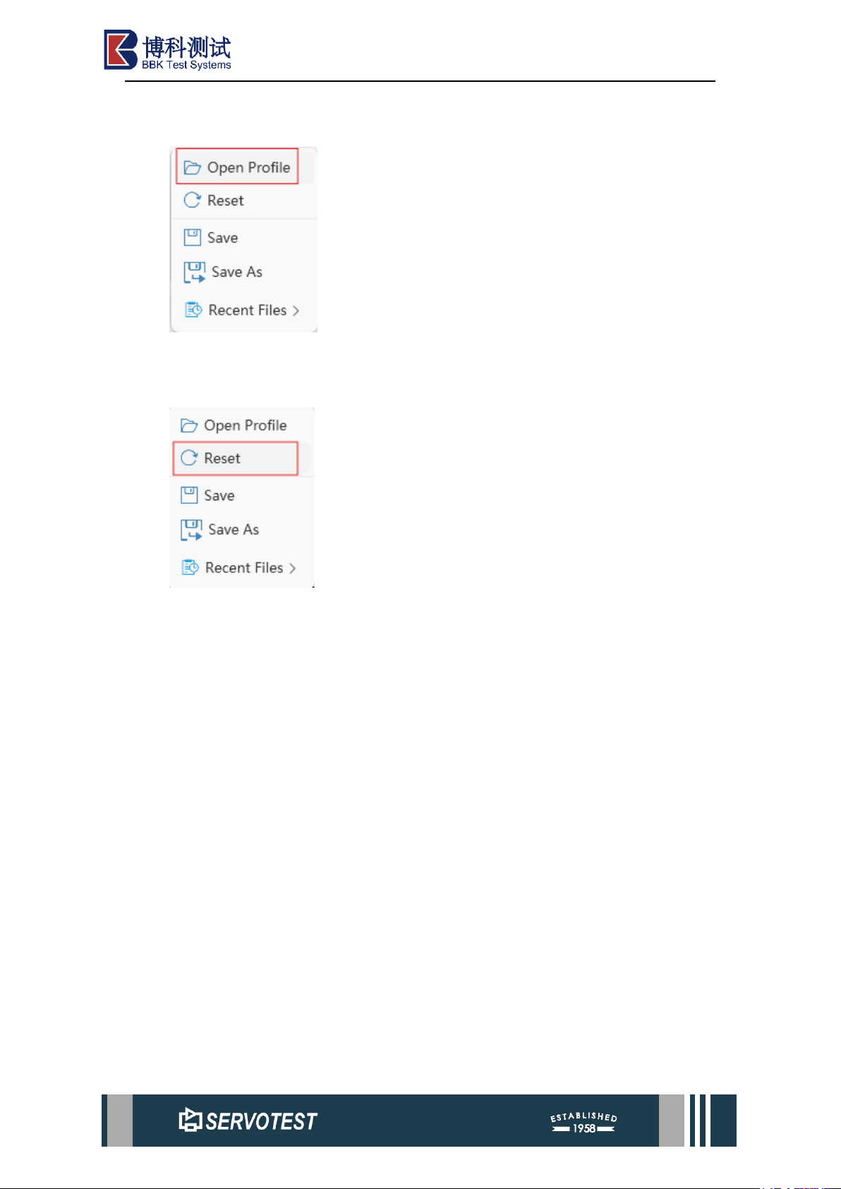
File settings include select, open, reset, and save file functions.
Page 5
xKit Operation Manual
2.1.1.1 Open File
Open a saved file.
2.1.1.2 Reset
Reset all configurations as default.
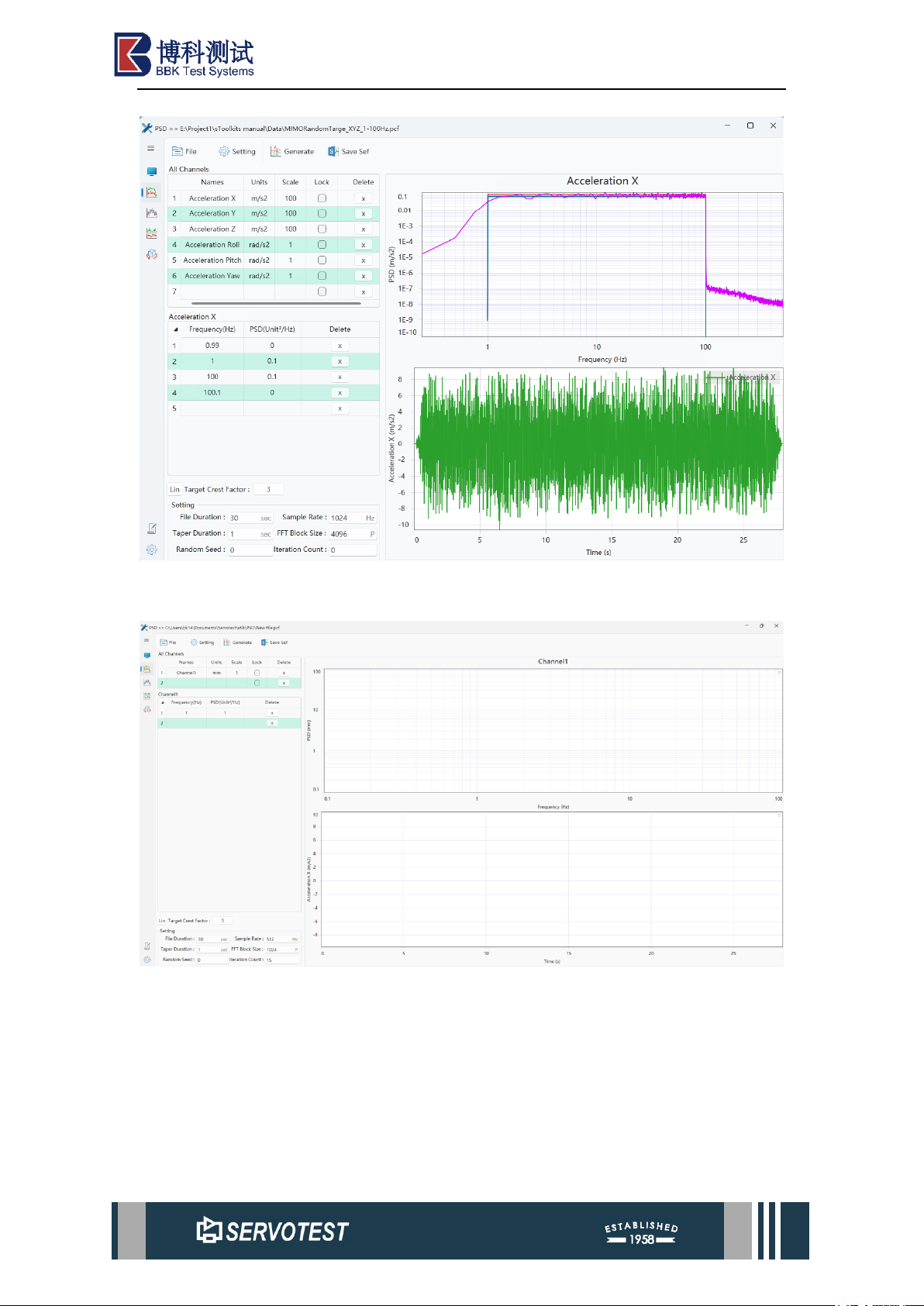
Note: Clicking ‘Reset’ to reset the parameter configuration is equivalent to
creating a new project file, and the corresponding file path will also change. If the
original project file has been modified but not saved, clicking ‘Reset’ to reset will
recreate a new project file, and the modified but unsaved parameters of the original
project file will not be saved.
Page 6
xKit Operation Manual
Figure 2-2 Parameters before reset
Figure 2-3 Parameters after reset
Page 7
xKit Operation Manual
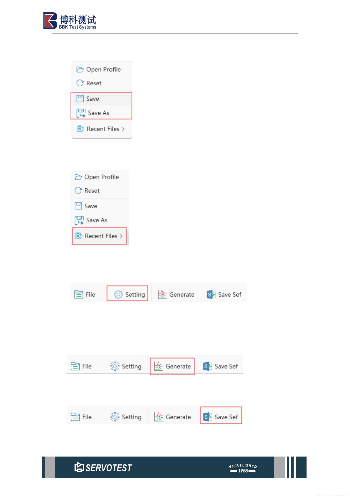
2.1.1.3 Save
Save the file or save it as a file, with "*" means the current file is not saved.
2.1.1.4 Select Document
Files can display the most recently used files, The number of displayed files and
the number of saved files can be adjusted in the options, up to a maximum of 10 files.
2.1.2 Setting
General settings include four parts: system settings, software language switching,
software help menu, and software information menu. All functions are open except for
the language switching function.
2.1.3 Generate
Click this button to draw the image after setting the parameters.
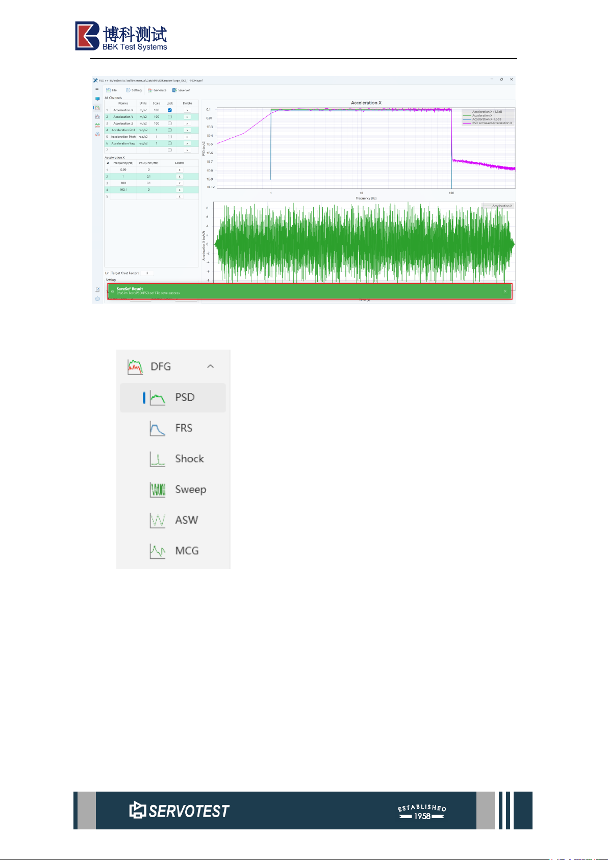
2.1.4 Save Sef
Save as a .sef file. After successful saving, the storage path information of the .sef
file will be displayed, as shown in the figure below.
Page 8
xKit Operation Manual
Figure 2-4 Prompt Message
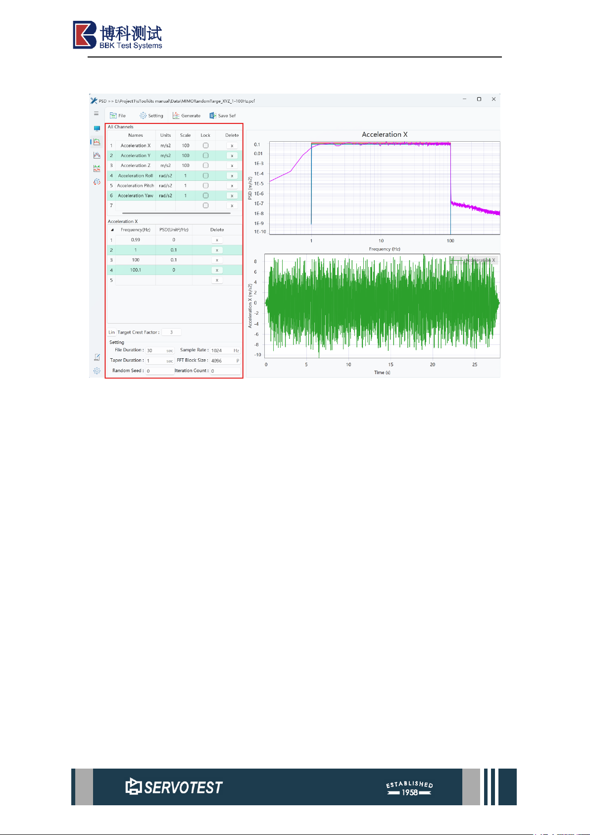
2.2 Function Switching
Click the drop-down menu button to the right of ‘DFG’ to switch between the six
functions in the DFG module. These are PSD, FRS, Shock, Sweep, ASW, and MCG.
Page 9
xKit Operation Manual
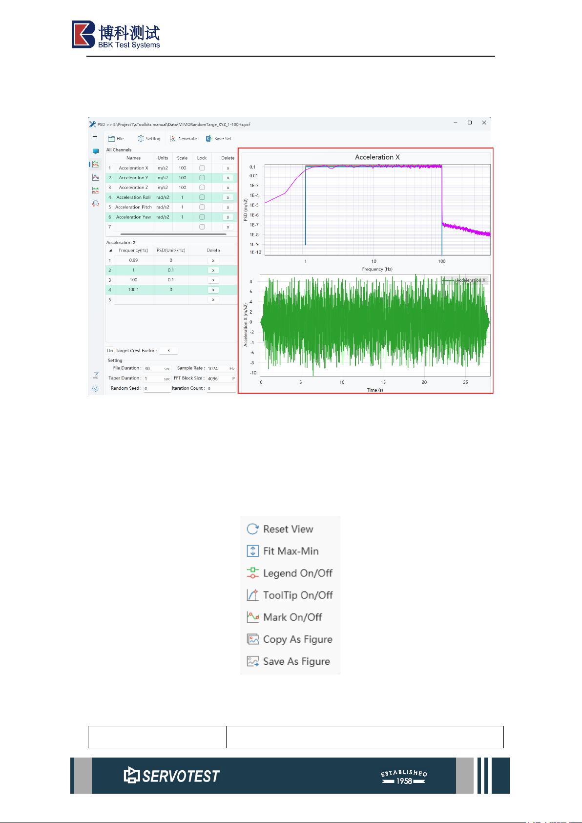
2.3 Parameter Setting Area
Figure 2-5 Parameter Setting Area
The parameter setting area is generally on the left half of the main interface, as
shown in the red part in the figure above. The parameter setting area is different for
each function. They will be introduced in detail in the following chapters.
Page 10
xKit Operation Manual
2.4 Drawing Function Area
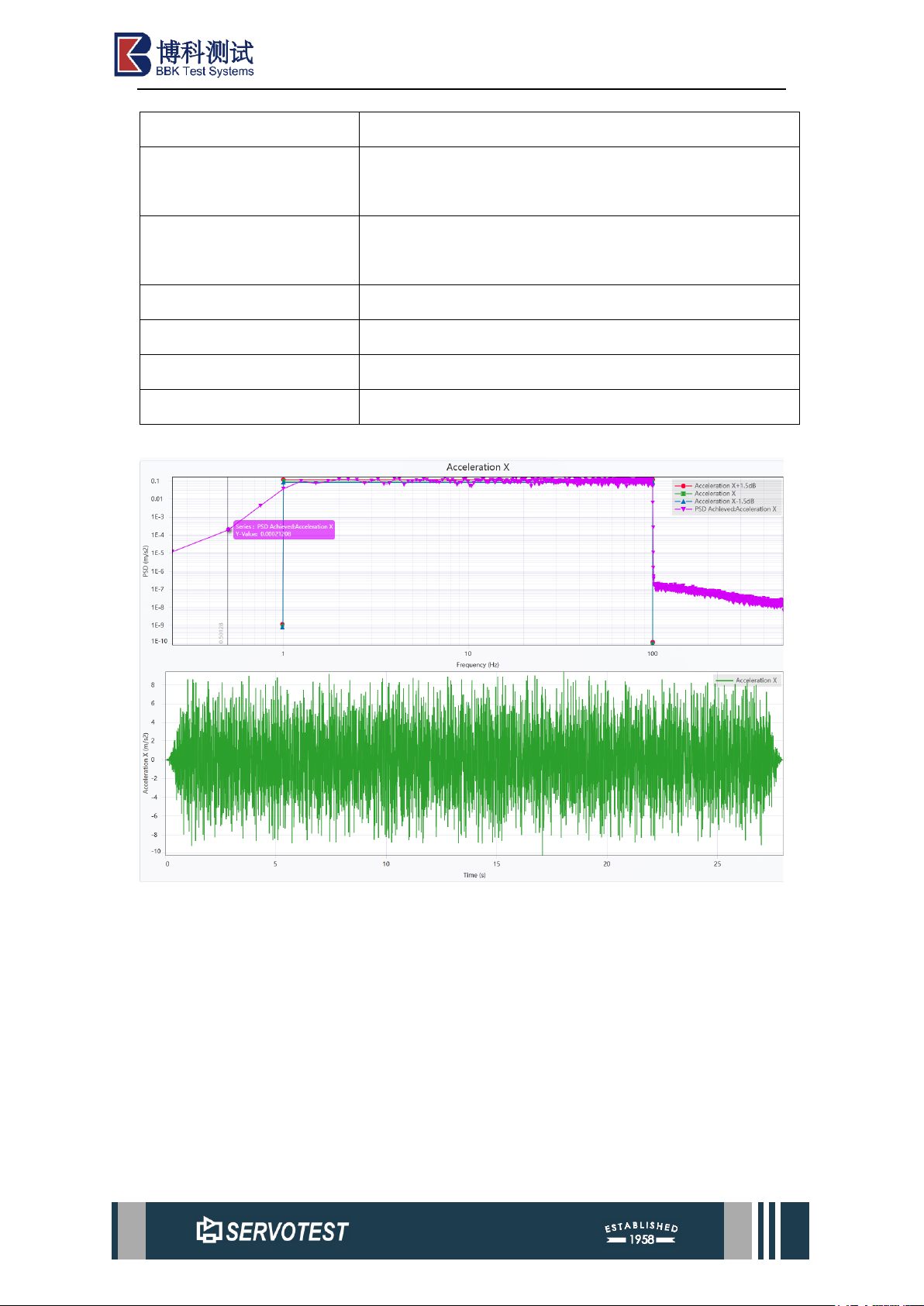
2.4.1 Data Graph
Figure 2-6 Data Graph Area
Click the ‘Generate’ button, and the software will automatically draw a data graph.
The data graph area can be adjusted using the mouse wheel to change the drawing
coordinate range. Different images are drawn in the drawing area depending on the
function.
2.4.2 Right-click Menu
Figure 2-7 Right-click Menu
Right-click the drawing area to call out the menu options as shown above.
Table 2-1 Right-click Menu
Parameter
Describe
Page 11
xKit Operation Manual
Reset View
Reset the coordinate range of the drawing area.
Fit Max/Min
Automatically adjust the Y-axis coordinate range to the
range of the data, and the X-axis is not affected.
Legend On/Off
Option to turn on or off the legend in the upper right
corner.
ToolTip On/Off
Turn on or off the function switch of mouse display data.
Mark On/Off
Toggle the display of individual data points on or off.
Copy as Figure
Copy the image to the clipboard.
Save as Figure
Save as image file.
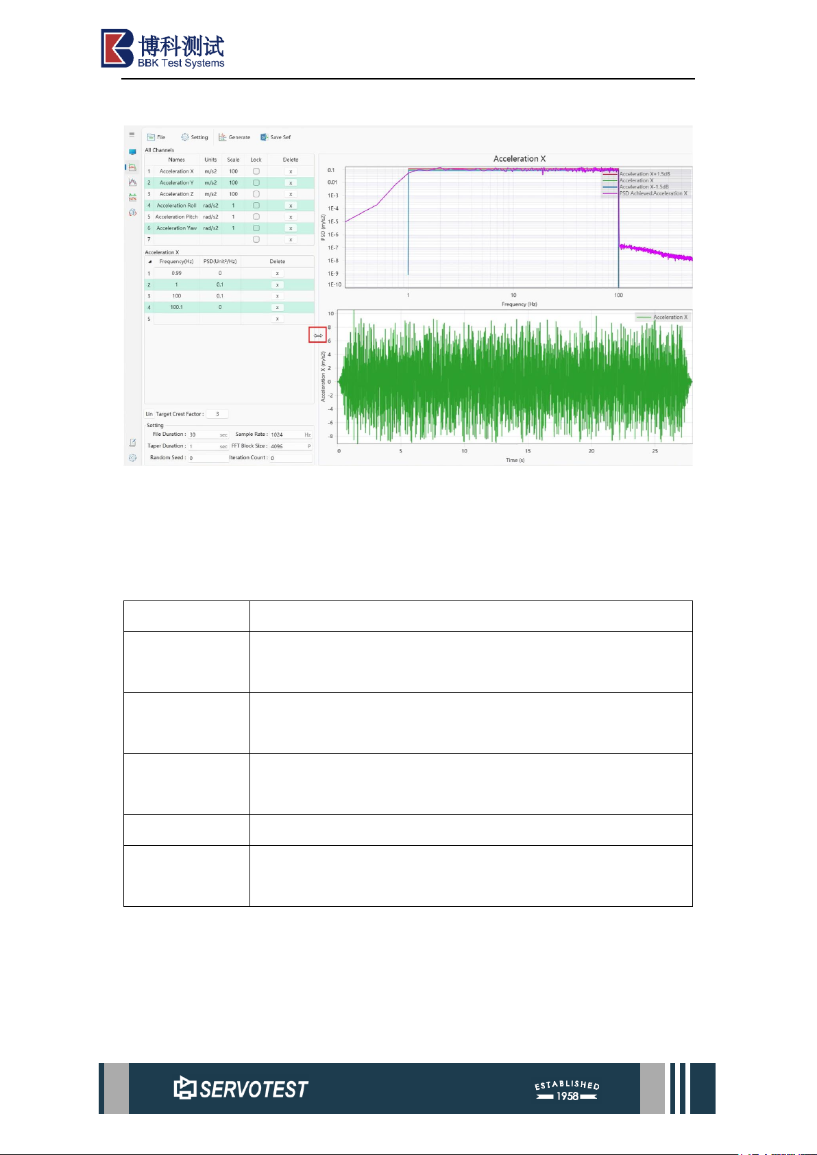
Part of the functional effect is shown in the figure below.
Figure 2-8 Data Graph Example
Page 12
xKit Operation Manual
2.5 Adjust Area Size
Figure 2-9 Adjust Area Size
As shown in the figure, the pointer will change automatically in the middle line of
the area. The area size can be adjusted.
2.6 Supported Image Formats
Table 2-2 Supported Formats
Format
Describe
png
png is short for Portable Network Graphic, a type of raster image
file.
jpg
jpg is a widely used compressed image format for containing
digital images.
svg
Scalable Vector Graphics (svg) is a web-friendly vector file
format.
pdf
pdf is an abbreviation that stands for Portable Document Format.
emf
An emf file is a Windows file format designed to store large
amounts of image detail for high quality printing.
2.7 Middle Scroll Wheel
2.7.1 Double Click
Double-clicking the scroll wheel will quickly reset the display range of the chart
to the default range.
Page 13
xKit Operation Manual
2.7.2 Scrolling of Middle Wheel
Scrolling the mouse wheel can zoom in and out of the chart.
3 DFG function introduction
DFG consists of five functional modules, including: PDS, FRS, Shock, Sweep,
ASW and MCG.
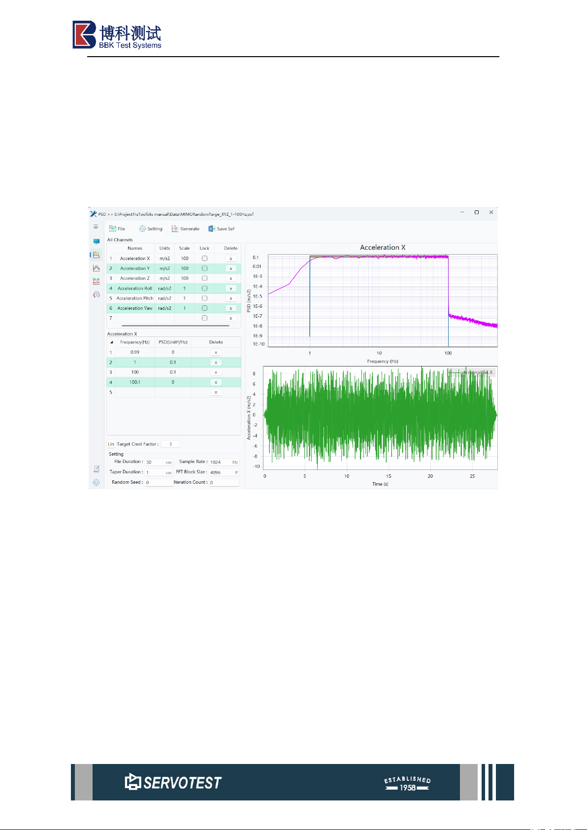
3.1 PSD Module
Figure 3-1 PSD Main User Interface
Page 14
xKit Operation Manual
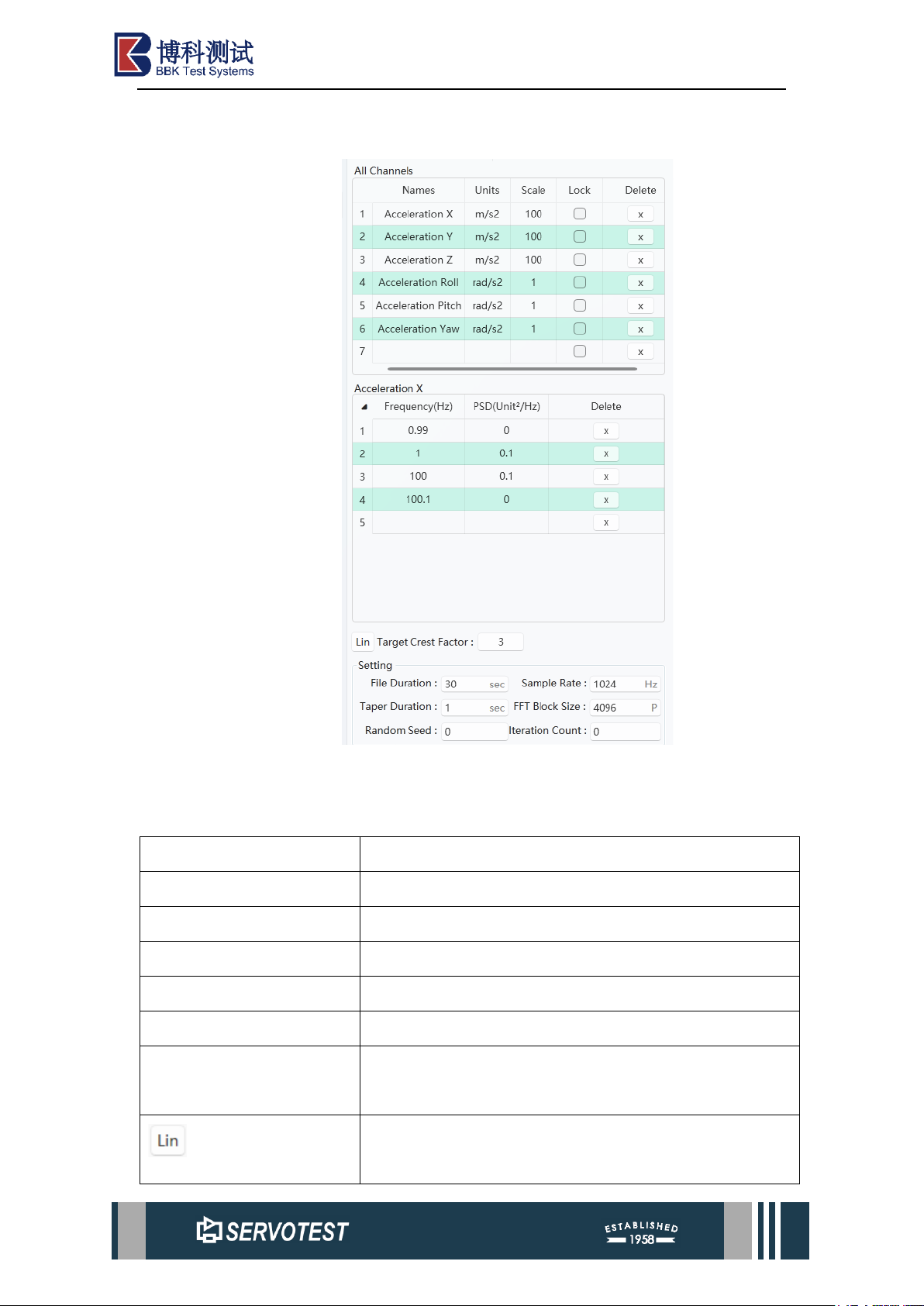
3.1.1 PSD Setting Area
Figure 3-2 PSD Setting Area
Table 3-1 PSD Setting Area
Parameter
Describe
Names
Names.
Units
Units.
Scale
Scale.
Lock
Lock.
Frequency(Hz)
Frequency, measured in Hz.
PSD(Unit2/Hz)
Power spectral density, energy density at a certain
frequency.
Click the ‘Lin’ button to switch between linear power
spectrum and logarithmic power spectrum.
Page 15

xKit Operation Manual
Target Crest Factor
Target Crest Factor.
File Duration
File Duration.
Sample Rate
Sampling rate, the default is 1024Hz.
Taper Duration
Decrease the duration of the attenuation.
FFT Block Size
Fast Fourier Transform (FFT) cutoff frequency.
Random Seed
Random Seed.
Iteration Count
Iteration Count.
3.1.2 PSD Formats
Each module has some different file suffixes and format requirements, as follows.
Table 3-2 PSD Formats
Extensions
Format Description
Pcf
Binary file: This file type is the default type of the original DFG
file. It is a binary file. It saves all parameters of the PSD except
the random number setting. It is compatible with the data format
of the previous version of DFG.
Pcfx (xml)
This file type is a file type customized by the software after
upgrading the previous version of DFG to distinguish it from
other software systems. Lock two parameters, the file format
specification is highly readable.
3.1.3 Other Features
⚫ After switching, the program defaults to open the file configuration when it
was closed or switched last time. If it is the first time to open, it is the default
parameter.
⚫ There are two methods for deleting rows within a table area: firstly, use the
corresponding ‘Delete’ button for the table area to remove the relevant row;
alternatively, select the rows to be deleted and press the ‘Delete’ key to
remove them.
Page 16
xKit Operation Manual
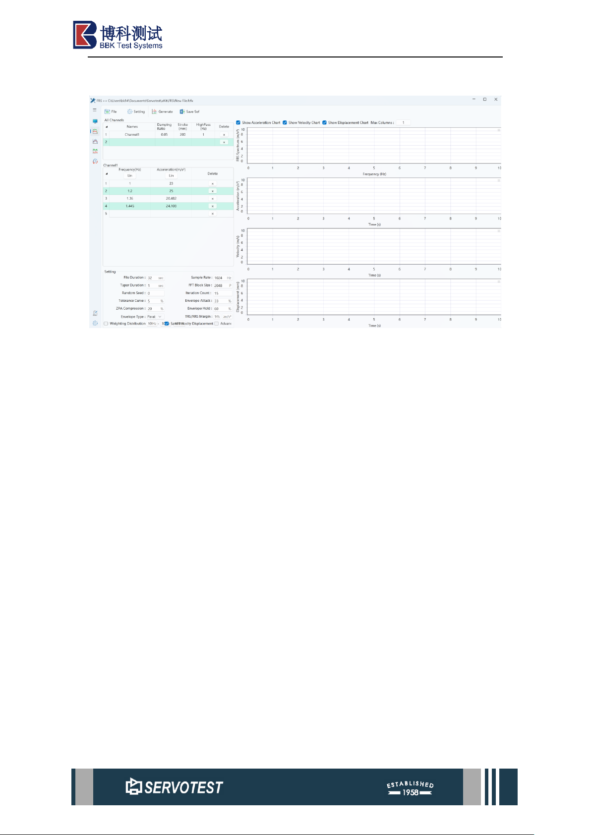
3.2 FRS Module
Figure 3-3 FRS Main User Interface
FRS is an update to previous versions.
Page 17
xKit Operation Manual
3.2.1 FRS Setting Area
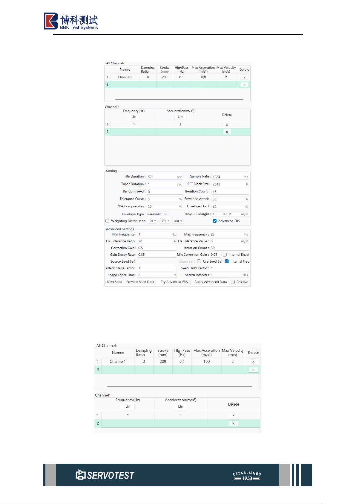
Figure 3-4 Left Parameter Settings
The parameter settings area on the left side of the FRS main interface includes
three parts: channel parameter settings, settings, and advanced settings.
3.2.1.1 Channel Settings
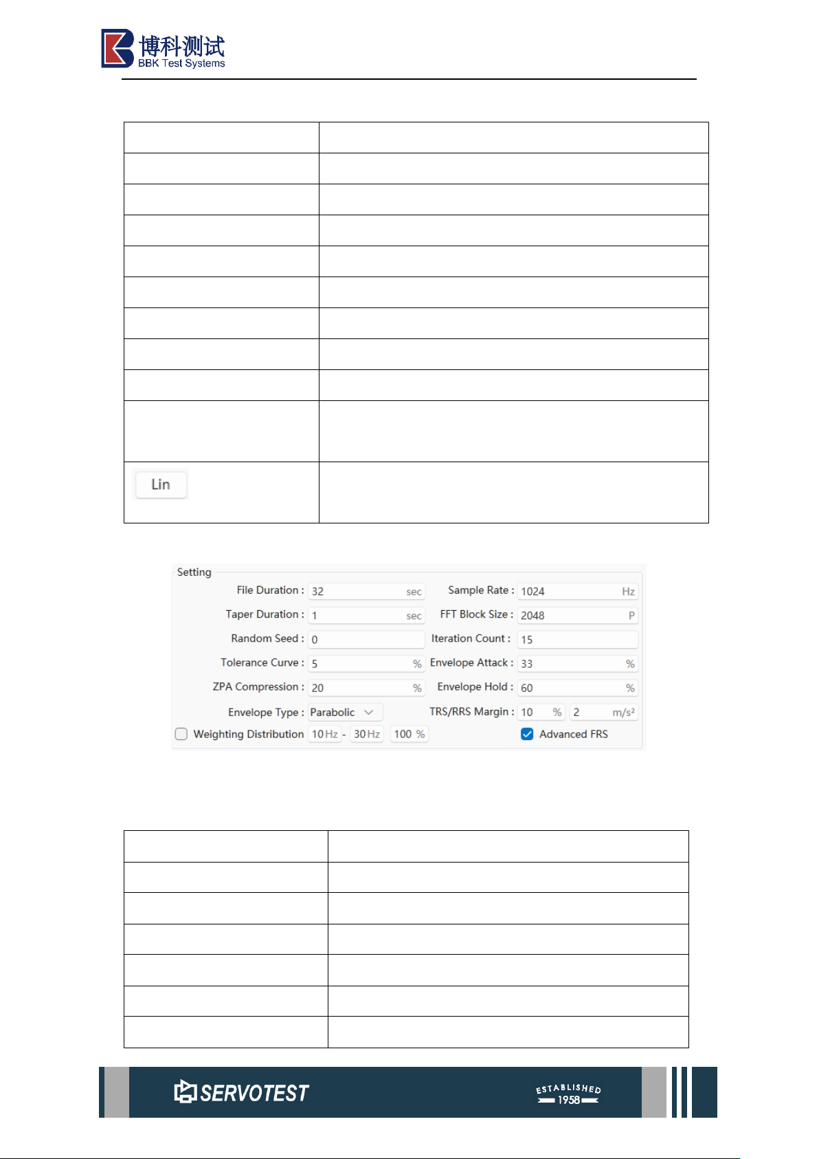
Figure 3-5 Channel Parameter Settings
Page 18
xKit Operation Manual
Table 3-3 Channel Parameter Settings
Parameter
Describe
Names
Channel name.
Damping Ration
Damping Ration.
Stroke
Stroke.
High Pass (Hz)
High-pass filter (Hz).
Max Acceleration(m/s2)
Max Acceleration(m/s2).
Max Velocity(m/s)
Max Velocity(m/s).
Delete
Click to delete the entire row.
Frequency (Hz)
Frequency, measured in Hz.
Acceleration (m/s2)
Power spectral density, energy density at a certain
frequency.
Click the “Lin” button to switch between linear and
logarithmic scales..
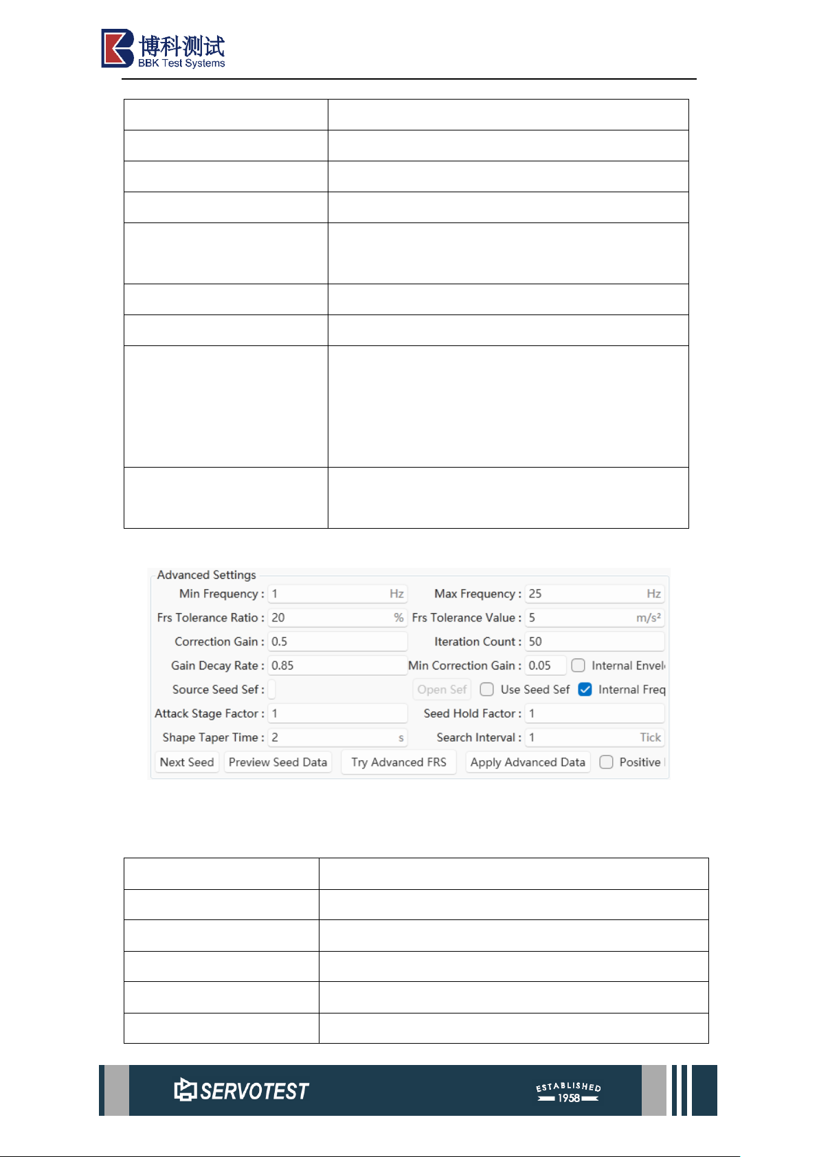
3.2.1.2 Setting
Figure 3-6 Setting
Table 3-4 Setting
Parameter
Describe
File Duration
File Duration.
Sample Rate
Sample Rate.
Taper Duration
Attenuation duration.
FFT Block Size
Fast Fourier Transform (FFT) cut-off frequency.
Random Seed
Random Seed.
Iteration Count
Iteration Count.
Page 19
xKit Operation Manual
Tolerance Curve
Tolerance Curve.
Envelope Attack
Envelope Attack.
ZPA Compression
ZPA Compression.
Envelope Hold
Envelope Hold.
Envelope Type
Envelope types: Includes Parabolic, Exponential,
and Linear.
TRS/RRS Margin
TRS/RRS Margin
Weighting Distribution
Weighted distribution.
Save Velocity Displacement
Tick the checkbox to save the velocity and
displacement time-domain plots when saving the .sef
file; leave unticked to save only the acceleration
time-domain plot when saving the .sef file.
Advanced FRS
Check the checkbox to configure the parameters in
the Advanced Settings section.
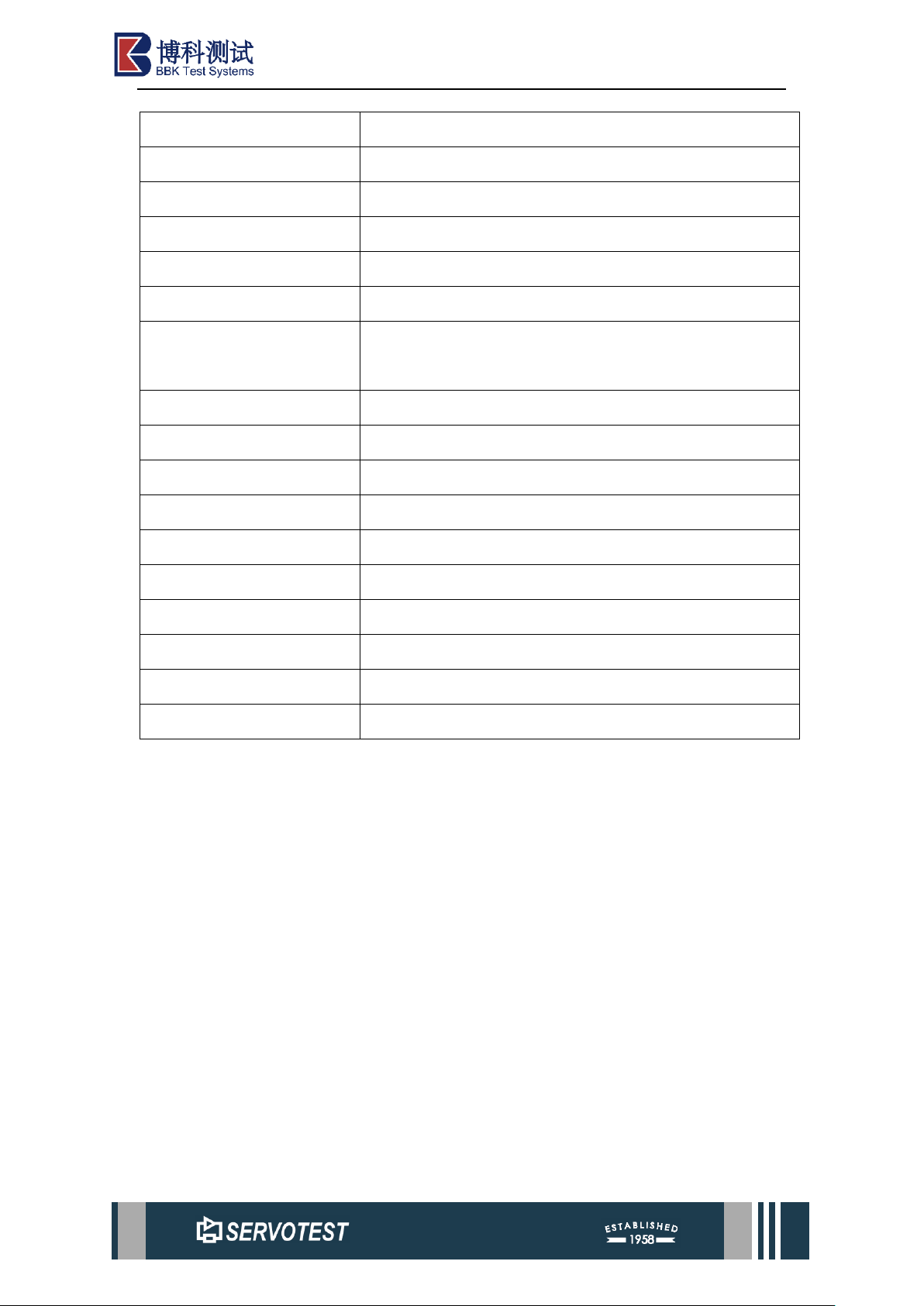
3.2.1.3 Advanced Settings
Table 3-5 Advanced Settings
Table 3-6 Advanced Settings
Parameter
Describe
Min Frequency
Min Frequency.
Max Frequency
Max Frequency.
Frs Tolerance Ratio
Error threshold percentage.
Frs Tolerance Value
Minimum error threshold.
Correction Gain
Correction Gain.
Page 20
xKit Operation Manual
Iteration Count
Iteration Count.
Gain Decay Rate
Gain attenuation gradient.
Min Correction Gain
Min Correction Gain.
Internal Envel
Internal envelope.
Source Seed Sef
Seed Sef file.
Open Sef
Open Sef file.
Use Seed Sef
Custom seed file. Tick the checkbox to select the use of a
custom seed file.
Internal Freq
Internal Frequency points.
Attack Stage Factor
Attack Stage Factor.
Seed Hold Factor
Seed Hold Factor.
Shape Taper Time
Shape Taper Time.
Search Interval
Schedule search interval.
Next Seed
Next seed.
Preview Seed Data
Preview Seed Data.
Try Advanced FRS
Advanced FRS correction.
Apply Advanced Data
Apply Advanced Data.
Positive Envelop
Positive Envelop.
Note:
(1) Internal Envelope When the Internal Envelope option is selected, two scenarios
apply: firstly, the generated acceleration envelope will default to using the acceleration
envelope from the random seed file; secondly, when the Use Custom Seed File option
is selected, it will utilise the acceleration envelope from the custom seed file. When the
Internal Envelope option is deselected, the acceleration envelope is generated based on
the envelope impact and envelope sustain parameters set for the region. This is
primarily used to customise acceleration envelopes to meet specific practical
requirements.
(2) Internal Frequency Points. When the Internal Frequency Points option is
selected, the programme will utilise its default frequency points when generating
response spectra. If this option is deselected, the programme will instead employ
frequency points calculated from the sampling frequency and FFT window size.
Page 21
xKit Operation Manual
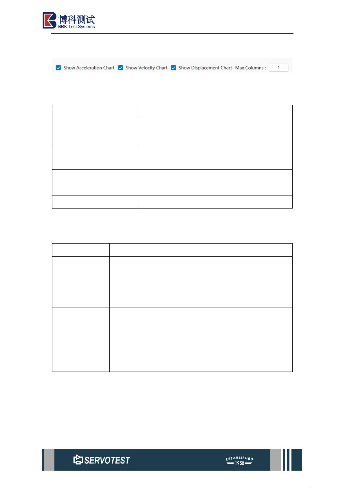
3.2.2 Drawing Display Settings
Figure 3-7 Drawing Display Settings
Table 3-7 Drawing Display Settings
Parameter
Describe
Show Acceleration Chart
Tick the checkbox to display the acceleration time-
domain graph in the plot area.
Show Velocity Chart
Tick the checkbox to display the speed time-domain
graph in the plot area.
Show Displacement Chart
Tick the checkbox to display the displacement time-
domain graph in the plot area.
Max Columns
Set the number of columns displayed in the plot.
3.2.3 FRS Formats
Table 3-8 FRS Formats
Extensions
Format Description
fcf
This file type is the default type of the original DFG file, which
is a binary file, and does not include parameters such as random
numbers, envelope types, weight distribution, etc., and is
compatible with the data format of previous versions of DFG.
fcfx (xml)
This file type is a file type customized by the software after
upgrading the previous version of DFG to distinguish it from
other software systems. Its file format is in xml format, covering
all parameters of FRS, and the file format specification is highly
readable.
3.2.4 Other Features
⚫ Added envelope type and weight distribution functions.
⚫ The parameters in the algorithm are the data added according to the latest
requirements.
⚫ The x-axis range of the AVD result chart remains the same, and reset works
on three charts at the same time.
Page 22
xKit Operation Manual
⚫ After switching, the program defaults to open the file configuration when it
was closed or switched last time. If it is the first time to open, it is the default
parameter.
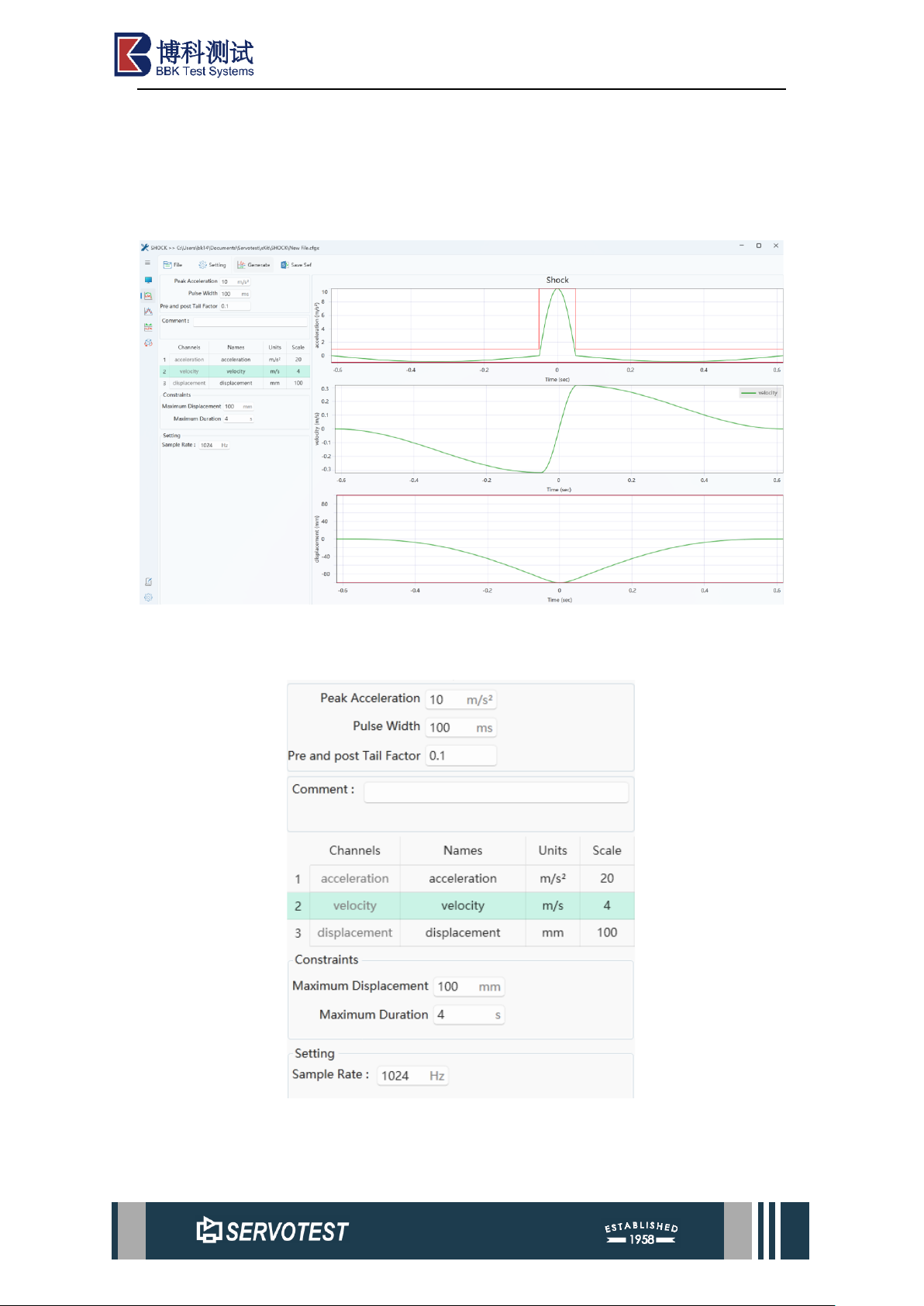
3.3 Shock Module
Figure 3-8 Shock Main User Interface
3.3.1 Shock Setting Area
Figure 3-9 Shock Setting Area
Page 23

xKit Operation Manual
Table 3-9 Shock Setting Area
Parameter
Describe
Peak Acceleration
Peak Acceleration.
Pulse Width
Pulse Width.
Pre and post Tail Factor
Factor.
Comment
Remarks.
Channels
Channels.
Names
Names.
Units
Units.
Scale
Scale.
Maximum Displacement
Maximum Displacement.
Maximum Duration
Maximum Duration.
Sample Rate
Sampling rate, the default is 1024Hz.
3.3.2 Shock Formats
Shock is the same as the previous version of DFG, adding the .cfgx file format.
3.3.3 Other Features
⚫ The x-axis range of the AVD result chart remains the same, and reset works
on three charts at the same time.
⚫ After switching, the program defaults to open the file configuration when it
was closed or switched last time. If it is the first time to open, it is the default
parameter.
Page 24
xKit Operation Manual
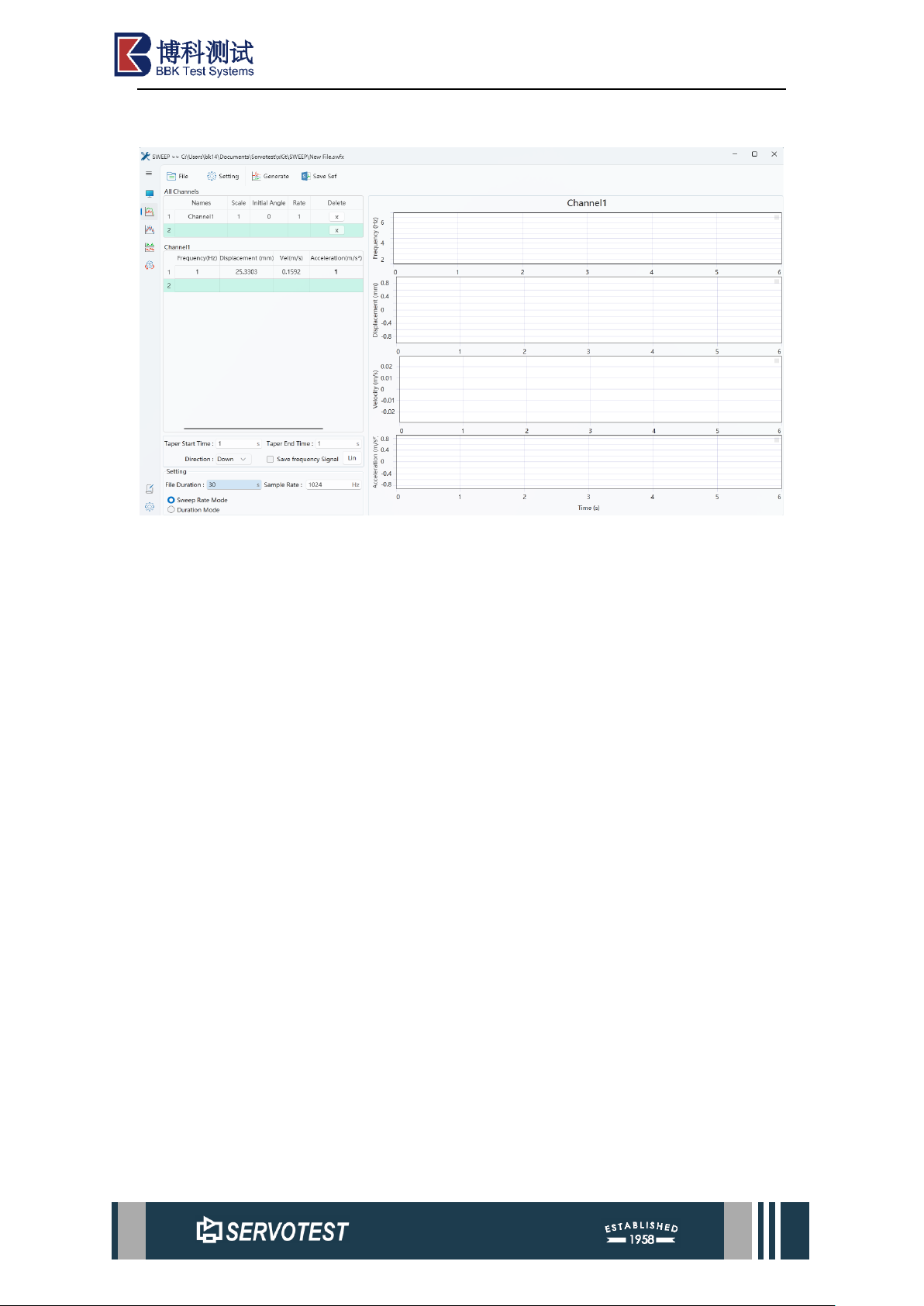
3.4 Sweep Module
Figure 3-10 Sweep Main User Interface
The Sweep module is used to generate a frequency sweep signal, which can be set
based on displacement, velocity, and acceleration.
Page 25
xKit Operation Manual
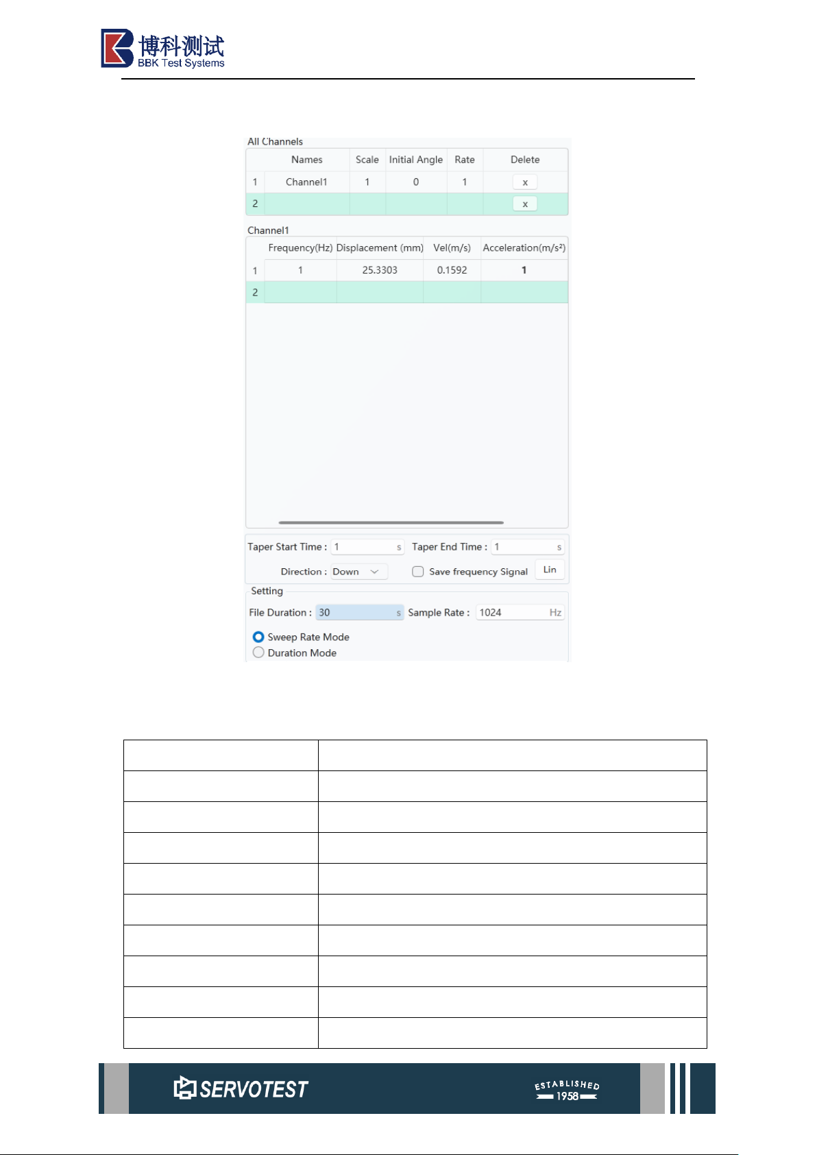
3.4.1 Sweep Setting Area
Figure 3-11 Sweep Setting Area
Table 3-10 Sweep Setting Area
Parameter
Describe
Names
Names.
Scale
Scale.
Initial Angle
Initial Angle.
Rate
Rate.
Delete
Click to delete the entire row.
Frequency(Hz)
Frequency(Hz).
Displacement(mm)
Displacement(mm).
Vel(m/s)
Velocity (m/s).
Acceleration(m/s2)
Acceleration(m/s2).
Page 26
xKit Operation Manual
Taper Start Time
Taper start time period.
Taper End Time
Taper end time period.
Direction
Sweep direction: Upward sweep, downward sweep.
Save frequency Signal
Tick the Save Frequency checkbox to save the time-
frequency plot when saving the Sef file; leave it unticked
to exclude the time-frequency plot from the Sef file.
Click the ‘Lin’ button to switch between linear sweep and
logarithmic sweep modes.
File Duration
File Duration.
Sample Rate
Sampling rate, the default is 1024Hz.
Sweep Rate Mode
Sweep Rate Mode.
Duration Mode
Check ‘Duration Mode’ to freely set the file duration.
3.4.2 Sweep Formats
Sweep is the same as the previous version of DFG, adding the “. Swfx” file format.
This file format is based on the “xml” format and is used for the sweep function.
3.4.3 Other Features
After switching, the program defaults to open the file configuration when it was
closed or switched last time. If it is the first time to open, it is the default parameter.
3.5 ASW Module
Figure 3-12 ASW Main User Interface
Page 27
xKit Operation Manual
3.5.1 ASW Introduction
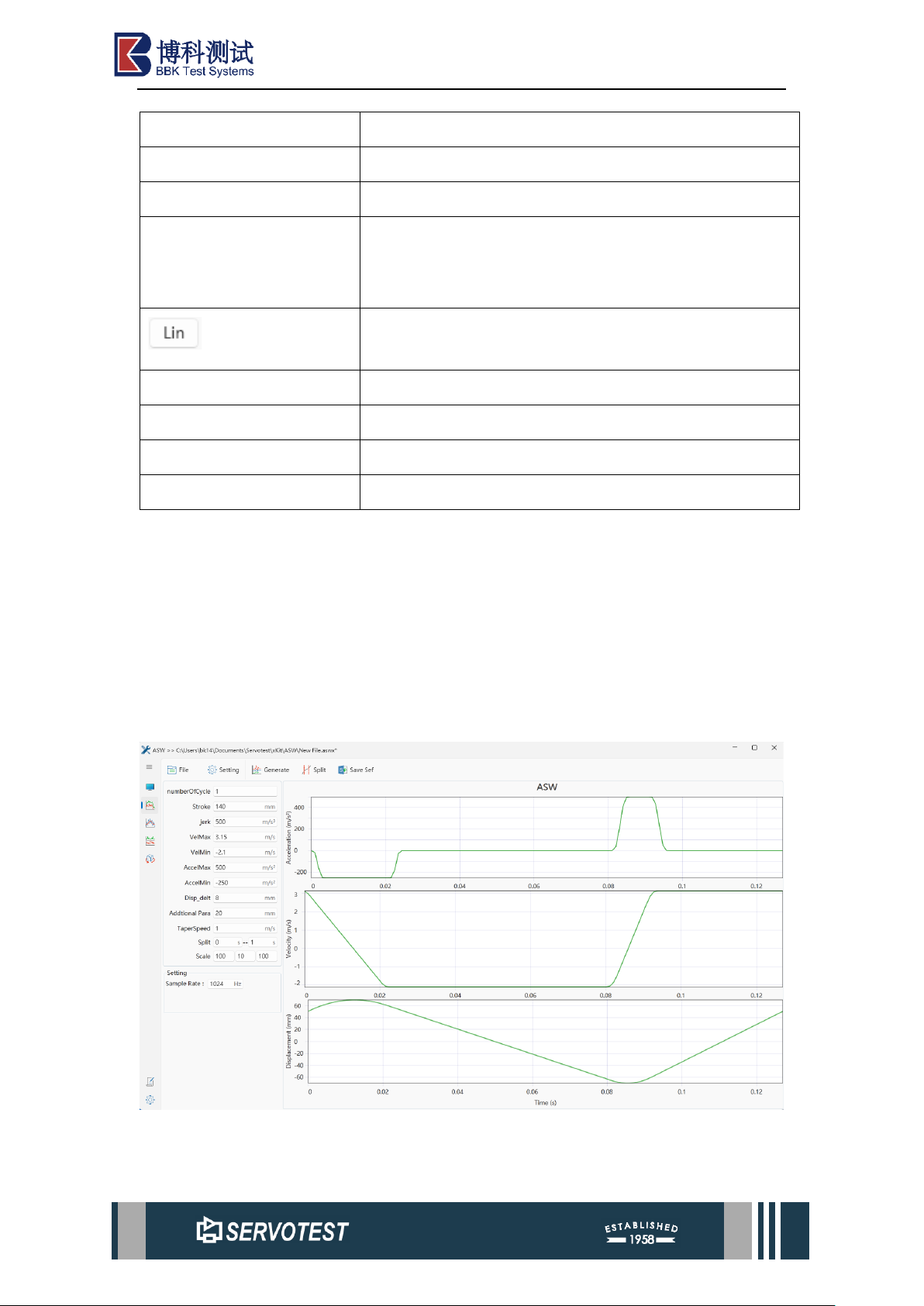
ASW is a curve generation tool for complex requirements.
Based on the ordinary sinusoidal curve, the maximum and minimum speed, the
maximum and minimum acceleration, the maximum and minimum stroke, and the ratio
of displacement to the total stroke under maximum performance are required at the
same time. This tool draws curves with different expressions according to the
requirements of each segment. The introduction of the jerk limit and the appropriate
adjustment of the maximum performance segment stroke ratio effectively expand the
parameter range of the curve that can be generated and realize the automatic adjustment
of the ratio of each segment. The effect is shown below.
The supported file type is “.aswx ”(xml file).
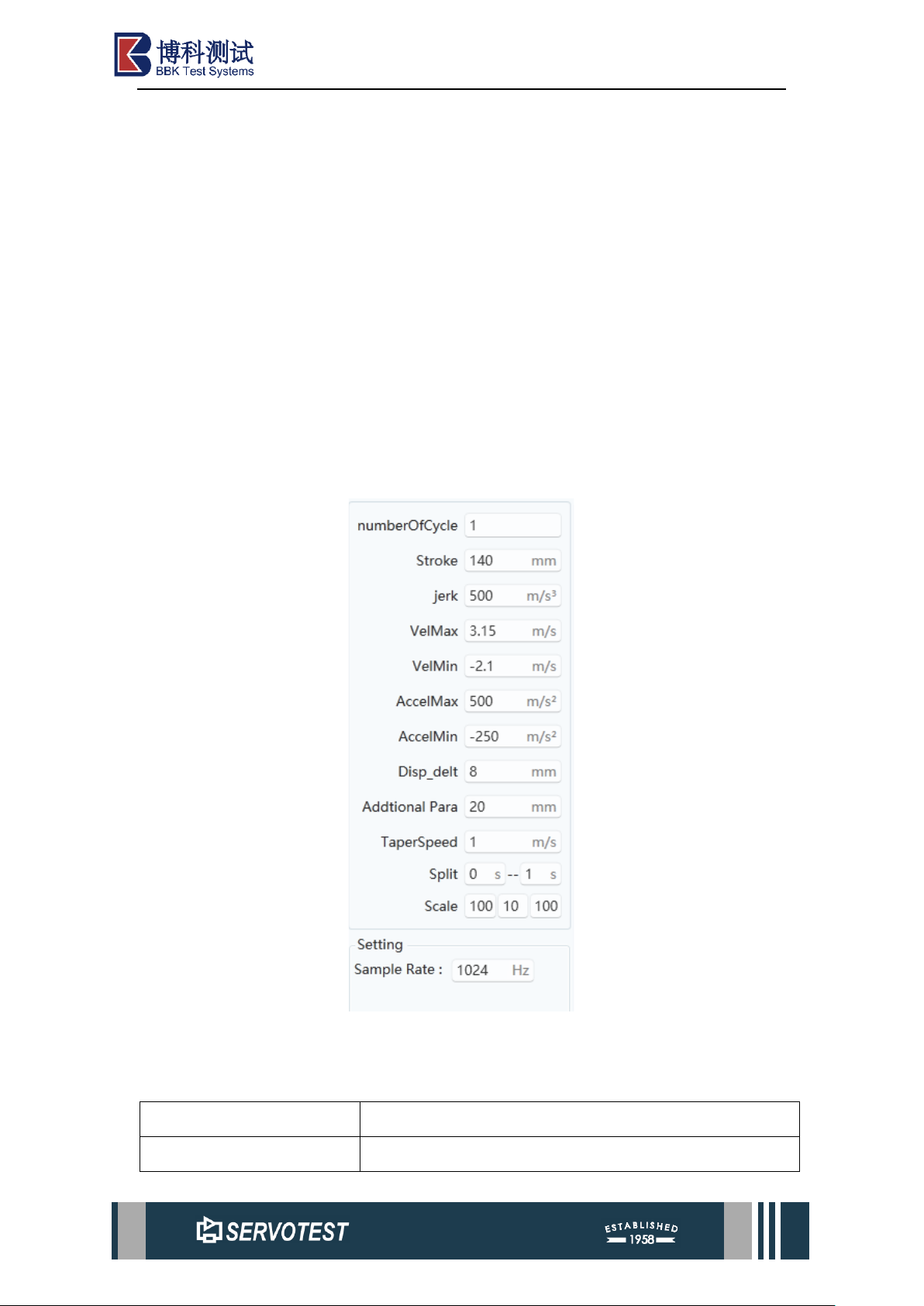
3.5.2 ASW Setting Area
Figure 3-13 ASW Setting Area
Table 3-11 ASW Setting Area
Parameter
Describe
NumberOfCycle
Number of cycles: the number of cycles of the drawn
Page 28
xKit Operation Manual
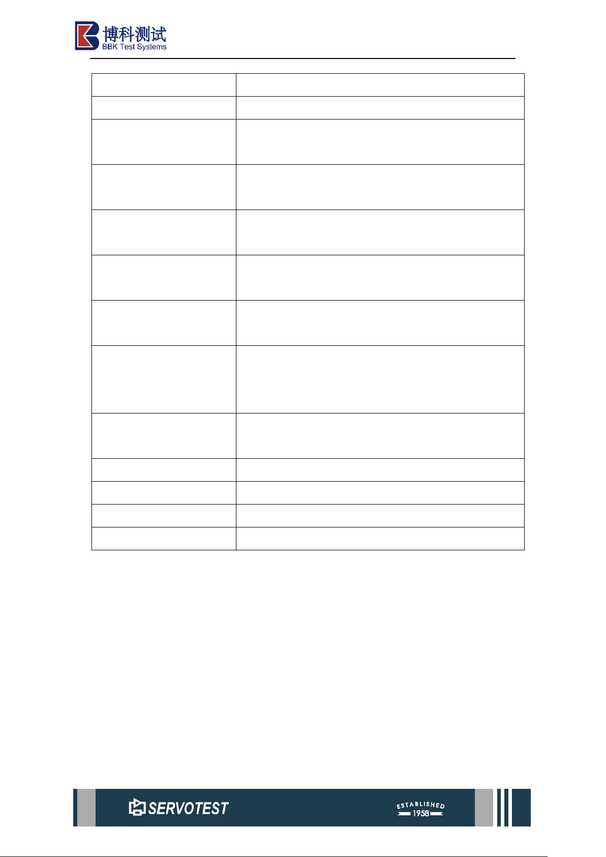
waveform.
Stroke
Full stroke: maximum to minimum displacement。
jerk
Jerk: An important parameter in the calculation process,
which reflects the maximum acceleration performance.
VelMax
Maximum Velocity: enter the maximum value of the
speed segment.
VelMin
Min Velocity: Enter the minimum value of the speed
segment.
AccelMax
Maximum Acceleration: Enter the maximum value of the
velocity segment.
AccelMin
Minimum Acceleration: Enter the maximum value of the
velocity segment.
Disp_delt
Displacement change: when the performance is
insufficient, the stroke of the constant speed section can
be ignored.
Additional Para
Additional parameters: when calculating an error, adjust
it appropriately, generally 20.
TaperSpeed
TaperSpeed.
Split
Set the start and end times for cutting.
Scale
Scale.
Sample Rate
Sampling rate, the default is 1024Hz.
3.5.3 Other Features
⚫ When the performance requirements are high (high speed in the constant
speed section, low acceleration upper limit, etc.), the displacement Delt and
additional parameters can be adjusted. Appropriate adjustment may sacrifice
the proportion of the constant speed section to produce a more consistent
result.
⚫ After switching, the program defaults to open the file configuration when it
was closed or switched last time. If it is the first time to open, it is the default
parameter.
Page 29
xKit Operation Manual
3.6 MCG Module
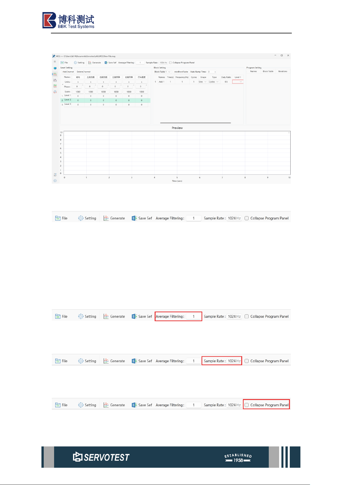
Figure 3-14 MCG Main User Interface
3.6.1 Main Menu
Figure 3-15 Main Menu
The main menu comprises seven sections: File, Settings, Generate Data Plot, Save
Sef File, Set Mean Filter, Set Sampling Frequency, and Folded Durability Settings
Parameter Panel. Operations concerning the File, Settings, Generate Data Plot, and
Save Sef File sections are detailed in Section 2.1, while the remaining three sections
are described below.
3.6.1.1 Mean Filter
Mean filter: Set the number of mean points.
3.6.1.2 Sample Rate
Sampling rate, the default is 1024Hz.
3.6.1.3 Collapse Program Panel
Page 30
xKit Operation Manual
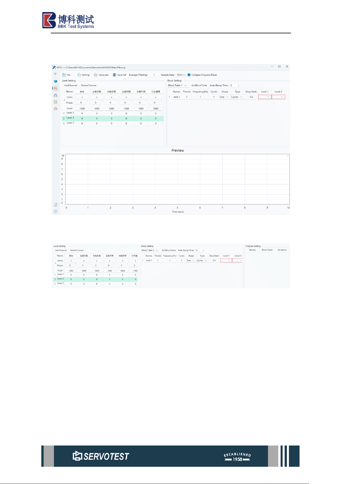
Click "Collapse Program Panel" to hide the parameters of the Program Setting
column. See the following figure for details.
Figure 3-16 Collapse Program Panel
3.6.2 MCG Setting Area
Figure 3-17 MCG Setting Area
The parameter setting area of the MCG module consists of three parts: Level
Setting, Block Setting, and Program Setting.
Page 31
xKit Operation Manual
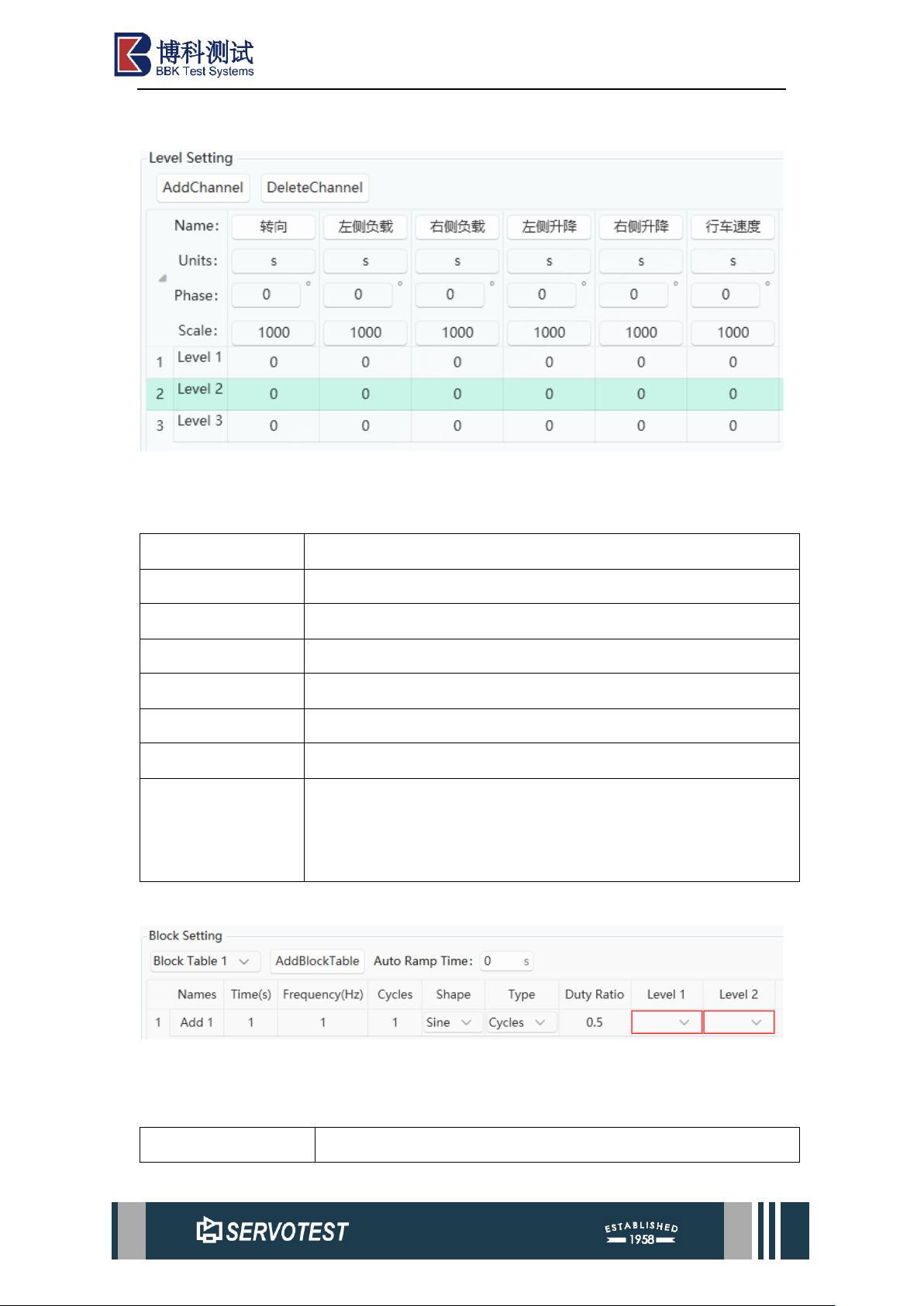
3.6.2.1 Level Setting
Figure 3-18 Level Setting
Table 3-12 Level Setting
Parameter
Describe
AddChannel
Add a new channel.
DeleteChannel
Delete channel.
Name
Set or display the current channel name.
Units
Unit.
Phase
Actuator or axial signal initial phase setting.
Scale
Scale.
Level 1
‘Level 1’ is the name of the Level row, which can be changed,
and the amplitude corresponding to each Level actuator or axis
can be set.
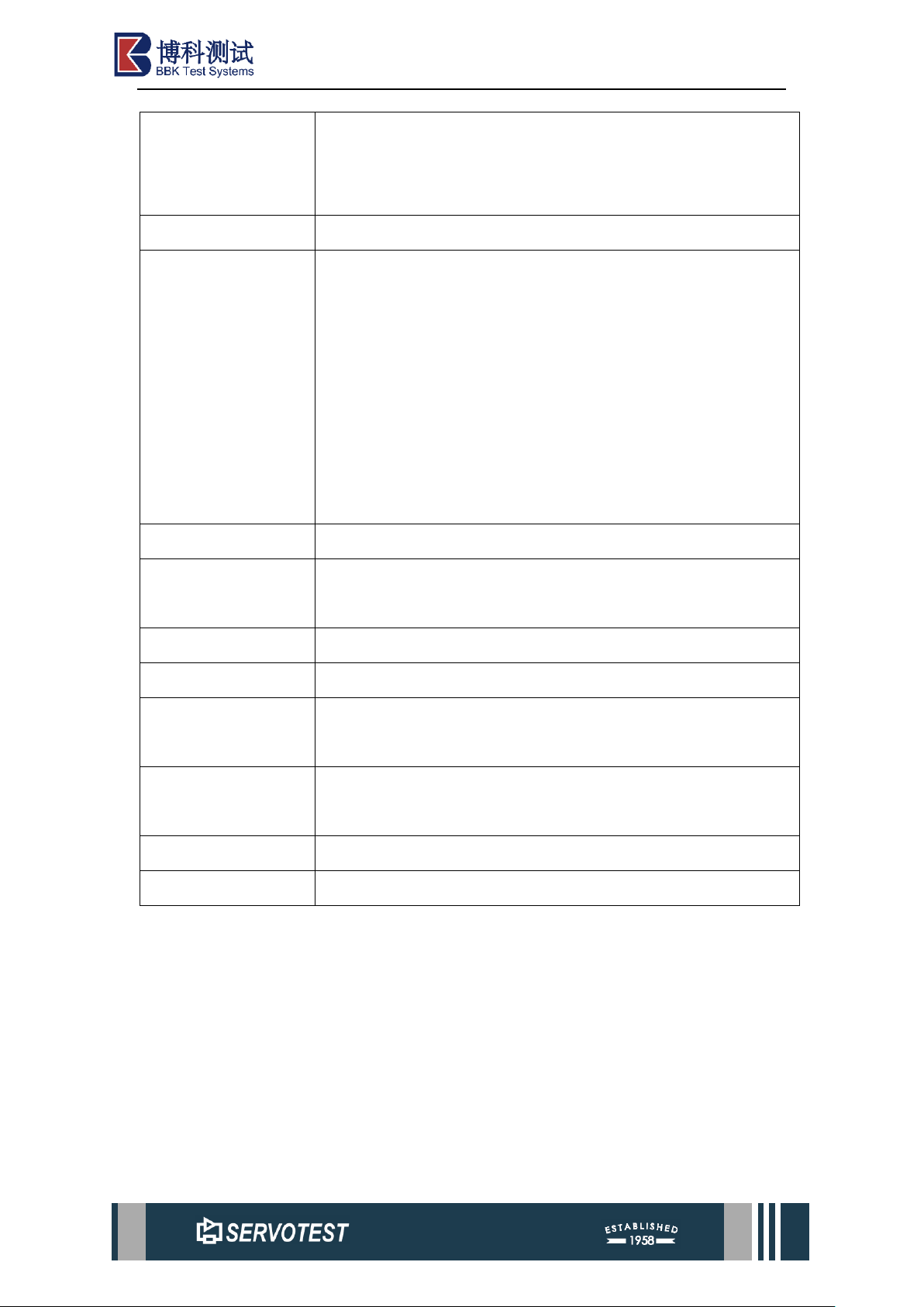
3.6.2.2 Block Setting
Figure 3-19 Block Setting
Table 3-13 Block Setting
Parameter
Describe
Page 32
xKit Operation Manual
Block Table 1
Displays the name of the currently selected Block Table. You
can switch between different Block Tables using the drop-down
list.
AddBlockTable
Add a new Block Table.
Auto Ramp Time
Set the parameter for the ramp transition time between
waveforms, with the unit being seconds (s). During multi-
signal switching, if the endpoint of the previous signal does not
align with the starting point of the current signal, a ramp
(Ramp) signal transition is typically required between
waveforms to prevent system impact. This parameter defines
the duration of the intermediate ramp signal transition. Note
that this time setting must not be less than 2 seconds.
Name
Set or display the name of the current Block Table row.
Time(s)
Waveform duration. This value is calculated automatically and
does not need to be configured manually.
Frequency(Hz)
Waveform frequency.
Cycles
Number of waveform cycles.
Shape
Waveform type: Select from the drop-down list: Sine, Triangle,
Square, Trapezoidal, SemiSine, SemiTrapezoidal.
Type
Waveform execution mode: Select ramp or cycles mode from
the drop-down list.
Duty Ratio
Duty Ratio.
Level 1/ Level 2
The maximum and minimum values of the waveform.
Note:
(1) A ramp waveform is a linearly changing signal, typically characterised by a
linear increase or decrease over time. Its characteristic is a continuous, monotonic
change that does not repeat.
(2) A cycle waveform is a periodically repeating signal. Common periodic
waveforms include sine waves, square waves, triangular waves, and sawtooth waves.
The characteristic of a periodic waveform is that the signal repeats at fixed time
intervals.
Page 33
xKit Operation Manual
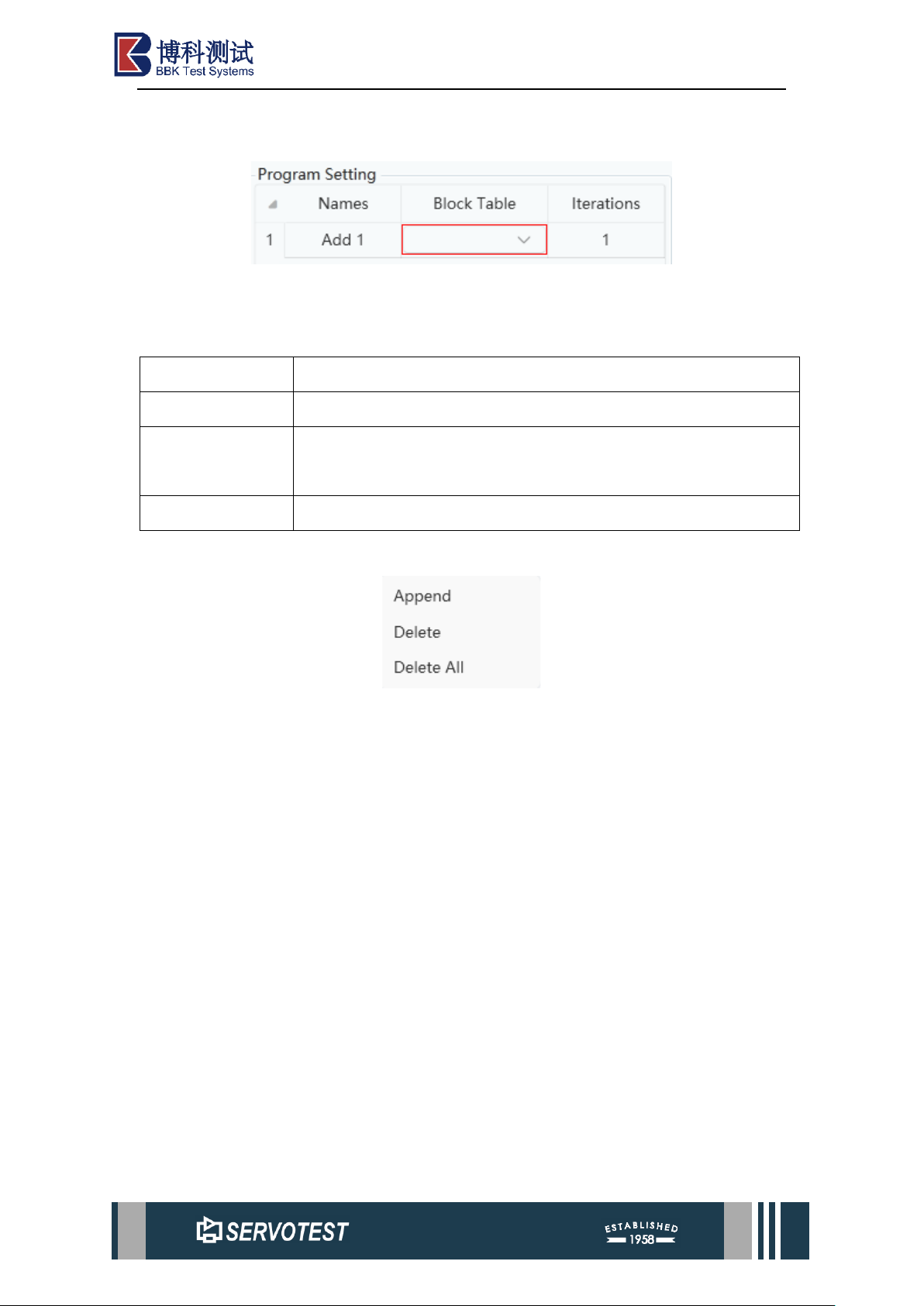
3.6.2.3 Program Setting
Figure 3-20 Program Setting
Table 3-14 Program Setting
Parameter
Describe
Name
Set or display the name of the current ProgramTable row.
Block Table
Displays the names of the currently selected Block Table. You can
switch between different Block Tables using the drop-down list.
Iterations
Block Table Number of loading cycles.
3.6.3 Right-click Menu
Figure 3-21 Right-click Men
Right-click on the ‘Level Setting’, ‘Block Setting’ and ‘Program Setting’
parameter areas to bring up the menu options shown in the figure above.
Append: Add a row below.
Delete: Delete the currently selected row.
Delete All: Delete all rows.
3.6.4 Other Features
After switching, the program defaults to open the file configuration when it was
closed or switched last time. If it is the first time to open, it is the default parameter.
 Loading...