


WARRANTY REGISTRATION FORMS AND PROCEDURES
MagnaSpread Pull-Type
WARRANTY REGISTRATION & DEALER INSPECTION FORM
The following section contains the necessary documents used to register a new BBI unit for warranty.
In order to activate the new equipment warranty, these forms should be returned to BBI no later than 30
(thirty) days from the date of sale to the end user.
These forms are in triplicate and distributed as follows:
1. Dealer retains one set for his / her records
2. One set returned to BBI
3. One set remains in operator’s manual and given to end user at time of delivery
These documents are as follows:
Dealer Inspection Form
This form is completed when the dealer is preparing to deliver the new unit to the end user. It certies
the dealer has inspected the equipment, it operates correctly and all safety signs and guards are in
place. Any modications made to the equipment by the dealer should also be noted.
Customer’s Warranty Registration
This form certies that the customer was instructed on safe and proper use, the equipment operates
correctly, warranty was explained and a copy of the owner’s manual was delivered. This form also
certies that if electronic rate control is installed, the customer has been given proper instruction as
to the operation of the system. Furthermore, a dealer service contact name and number has been
provided.
Important Tractor-Supplied Hydraulic Systems Information
This form certies that if the unit is equipped with Tractor Supplied Hydraulics, proper return
requirements were discussed.
Please return the executed copies to BBI within 30 days to activate the warranty.
The copies can be sent via email to: service@bbispreaders.com, faxed to: 706-778-2787,
or mailed to: BBI Spreaders P.O. Box 630 Cornelia, GA 30531.

DELIVERY INSPECTION - DEALER COPY
MagnaSpread Pull-Type
WARRANTY REGISTRATION & DEALER INSPECTION FORM
To have a fully-executed warranty, the dealer must ll this form out at time of delivery. There is no warranty
without a fully-executed warranty registration and dealer inspection form.
Model & Serial Number:
DEALER EQUIPMENT AND SAFETY INSPECTION REPORT
Equipment is properly assembled
Equipment congured as ordered
Equipment is functional and operates properly
All guards are in place
All warning signs and safety signs are in place
Modications to equipment (write details below)
Conveyor chain tension is properly adjusted
Comments / equipment modications:
Signature of Set-Up Person Dealer Name Date

CUSTOMER’S WARRANTY REGISTRATION - DEALER COPY
MagnaSpread Pull-Type
Dealer name:
Address:
City, State, Zip:
Model & Serial Number:
Date of Delivery:
Customer name:
Address:
City, State, Zip:
CUSTOMER’S WARRANTY REGISTRATION
Customer’s warranty protection on this equipment is only valid when this certication form is completed
and signed by both the customer and dealer at the time of delivery of the equipment and registered with
the manufacturer.
DEALER’S SIGNATURE INDICATES:
Equipment operates properly and customer was instructed in safe and proper operation
Customer received a copy of the operator’s manual
Warranty was explained to the customer
Electronic Rate control programmed and operates correctly
Chain tension and adjustment section reviewed and discussed
Signature of Dealer Dealer Name Date
CUSTOMER’S SIGNATURE INDICATES:
Acceptance of equipment
Receipt of owners manual and clear understanding of warranty
All systems were explained and understood
Receipt of instructions on safe and proper use
If equipped with Electronic Rate control, this system was explained and owner’s manual was received
A dealer parts/service representative contact has been provided
Clear understanding of chain tension and adjustment
Signature of Customer Customer Name Date

TRACTOR-SUPPLIED HYDRAULICS - DEALER COPY
MagnaSpread Pull-Type
IMPORTANT TRACTOR-SUPPLIED HYDRAULIC SYSTEMS INFORMATION
IMPORTANT!
On units equipped with tractor-supplied hydraulics the return must be connected to a 0 (zero) pressure
return. Gear motor systems require no pressure return.
DO NOT connect the system unless 0 (zero) pressure can be veried on return or damage to the motors
will result! Connecting to a pressurized return will VOID THE WARRANTY.
Various tractor manufacturers use different language for their brand to identify a 0 (zero) pressure return.
Please consult your manufacturer to insure the proper 0 (zero) pressure return is identied.
To maintain maximum operational efciency, your tractor needs to have 42 GPM (Gallons Per Minute)
overall, with 2 remotes each at 21 GPM and 2,000 PSI (Pounds per Square Inch) in order to operate the
tractor-supplied hydraulic system.
Signature of Dealer Dealer Name Date
Signature of Customer Customer Name Date

DEALER INSPECTION - BBI COPY
MagnaSpread Pull-Type
WARRANTY REGISTRATION & DEALER INSPECTION FORM
To have a fully-executed warranty, the dealer must ll this form out at time of delivery. There is no warranty
without a fully-executed warranty registration and dealer inspection form.
Model & Serial Number:
DEALER EQUIPMENT AND SAFETY INSPECTION REPORT
Equipment is properly assembled
Equipment congured as ordered
Equipment is functional and operates properly
All guards are in place
All warning signs and safety signs are in place
Modications to equipment (write details below)
Conveyor chain tension is properly adjusted
Comments / equipment modications:
Signature of Set-Up Person Dealer Name Date

CUSTOMER’S WARRANTY REGISTRATION - BBI COPY
MagnaSpread Pull-Type
Dealer name:
Address:
City, State, Zip:
Model & Serial Number:
Date of Delivery:
Customer name:
Address:
City, State, Zip:
CUSTOMER’S WARRANTY REGISTRATION
Customer’s warranty protection on this equipment is only valid when this certication form is completed
and signed by both the customer and dealer at the time of delivery of the equipment and registered with
the manufacturer.
DEALER’S SIGNATURE INDICATES:
Equipment operates properly and customer was instructed in safe and proper operation
Customer received a copy of the operator’s manual
Warranty was explained to the customer
Electronic Rate control programmed and operates correctly
Chain tension and adjustment section reviewed and discussed
Signature of Dealer Dealer Name Date
CUSTOMER’S SIGNATURE INDICATES:
Acceptance of equipment
Receipt of owners manual and clear understanding of warranty
All systems were explained and understood
Receipt of instructions on safe and proper use
If equipped with Electronic Rate control, this system was explained and owner’s manual was received
A dealer parts/service representative contact has been provided
Clear understanding of chain tension and adjustment
Signature of Customer Customer Name Date

TRACTOR-SUPPLIED HYDRAULICS - BBI COPY
MagnaSpread Pull-Type
IMPORTANT TRACTOR-SUPPLIED HYDRAULIC SYSTEMS INFORMATION
IMPORTANT!
On units equipped with tractor-supplied hydraulics the return must be connected to a 0 (zero) pressure
return. Gear motor systems require no pressure return.
DO NOT connect the system unless 0 (zero) pressure can be veried on return or damage to the motors
will result! Connecting to a pressurized return will VOID THE WARRANTY.
Various tractor manufacturers use different language for their brand to identify a 0 (zero) pressure return.
Please consult your manufacturer to insure the proper 0 (zero) pressure return is identied.
To maintain maximum operational efciency, your tractor needs to have 42 GPM (Gallons Per Minute)
overall, with 2 remotes each at 21 GPM and 2,000 PSI (Pounds per Square Inch) in order to operate the
tractor-supplied hydraulic system.
Signature of Dealer Dealer Name Date
Signature of Customer Customer Name Date

OPERATOR MANUAL
This manual is valid for all MagnaSpread
Pull-Type congurations
Your serial number can be found here:
10’, 12’, 14’, 16’ Tandem-axle
Tractor-supplied or self-contained
MagnaSpread Options:
8’, 10’ Single-axle
hydraulic systems

TABLE OF CONTENTS
MagnaSpread Pull-Type
2 TABLE OF CONTENTS
3 A MESSAGE FROM BBI
4-6 DELIVERY AND WARRANTY CHECKLISTS
7 WARRANTY
8-10 SAFETY INSTRUCTIONS
11 TRACTOR PREPARATION AND HOOK-UP
12 HYDRAULIC CONFIGURATION
13-17 IDENTIFYING COMPONENTS
18-21 FIELD TESTING
22-23 MACHINE OPERATION
24-25 LUBRICATION AND MAINTENANCE
26-28 CHAIN TENSION ADJUSTMENT
29 TIPS & TRICKS
30 PARTS AND SHIPPING
31 PARTS IDENTIFICATION AND ORDERING
32-48 ASSEMBLY AND PARTS IDENTIFICATION
49-54 GROUND SPEED TABLES AND RATE CHARTS
2

MagnaSpread Pull-Type
A MESSAGE FROM BBI
The BBI team takes pride in producing superior spreaders that will provide many years of
service. In bringing the best spreaders to the industries of agriculture, poultry, and construction,
we carefully select components with a proven performance record and availability. Our skilled
employees give special attention to detail in design and assembly to make certain our equipment
will meet or exceed your expectations in the eld.
Our parts department stands ready to serve you with replacement parts at affordable prices. We
stock a large inventory to assure support for our customers, and take pride in offering “same day
service” for those orders received before mid-afternoon.
At BBI, we provide quality service with a friendly atmosphere. BBI stands hand-in-hand with our
dealers in the eld. Our local dealers are your rst point of contact and empowered to solve your
problems. If that fails, we are prepared to serve you at any time. We strive to quickly provide
solutions for your needs in order to minimize any downtime or delays.
Our company takes safety very seriously, and we give great concern to our products in an
ongoing effort to reduce any potential safety issues, whether with equipment or in the workplace.
We design our equipment intentionally to minimize pinch points and provide guards where they
do exist. BBI places decals on our equipment to identify and caution against areas containing
pinch points and hazardous moving parts.
Please be sure that those who operate BBI equipment receive proper training. Never conduct
maintenance or repairs unless the equipment is fully disabled with the power source turned
off. Never stand inside the unit while in operation or moving. Since we design our spreaders to
project materials in patterns ranging from 30 to 90 feet, depending on the specic equipment,
standing too close to equipment can result in injury. Please use extreme caution when operating
all equipment.
Thank you for choosing BBI spreading equipment. You will be glad you did.
Richard B. Hagler
President
“Driving Value”
3

DELIVERY INSPECTION - CUSTOMER COPY
MagnaSpread Pull-Type
WARRANTY REGISTRATION & DEALER INSPECTION FORM
To have a fully-executed warranty, the dealer must ll this form out at time of delivery. There is no warranty
without a fully-executed warranty registration and dealer inspection form.
Model & Serial Number:
DEALER EQUIPMENT AND SAFETY INSPECTION REPORT
Equipment is properly assembled
Equipment congured as ordered
Equipment is functional and operates properly
All guards are in place
All warning signs and safety signs are in place
Modications to equipment (write details below)
Conveyor chain tension is properly adjusted
Comments / equipment modications:
Signature of Set-Up Person Dealer Name Date
4

CUSTOMER’S WARRANTY REGISTRATION - CUSTOMER COPY
MagnaSpread Pull-Type
Dealer name:
Address:
City, State, Zip:
Model & Serial Number:
Date of Delivery:
Customer name:
Address:
City, State, Zip:
CUSTOMER’S WARRANTY REGISTRATION
Customer’s warranty protection on this equipment is only valid when this certication form is completed
and signed by both the customer and dealer at the time of delivery of the equipment and registered with
the manufacturer.
DEALER’S SIGNATURE INDICATES:
Equipment operates properly and customer was instructed in safe and proper operation
Customer received a copy of the operator’s manual
Warranty was explained to the customer
Electronic Rate control programmed and operates correctly
Chain tension and adjustment section reviewed and discussed
Signature of Dealer Dealer Name Date
CUSTOMER’S SIGNATURE INDICATES:
Acceptance of equipment
Receipt of owners manual and clear understanding of warranty
All systems were explained and understood
Receipt of instructions on safe and proper use
If equipped with Electronic Rate control, this system was explained and owner’s manual was received
A dealer parts/service representative contact has been provided
Clear understanding of chain tension and adjustment
Signature of Customer Customer Name Date
5

TRACTOR-SUPPLIED HYDRAULICS - CUSTOMER COPY
MagnaSpread Pull-Type
IMPORTANT TRACTOR-SUPPLIED HYDRAULIC SYSTEMS INFORMATION
IMPORTANT!
On units equipped with tractor-supplied hydraulics the return must be connected to a 0 (zero) pressure
return. Gear motor systems require no pressure return.
DO NOT connect the system unless 0 (zero) pressure can be veried on return or damage to the motors
will result! Connecting to a pressurized return will VOID THE WARRANTY.
Various tractor manufacturers use different language for their brand to identify a 0 (zero) pressure return.
Please consult your manufacturer to insure the proper 0 (zero) pressure return is identied.
To maintain maximum operational efciency, your tractor needs to have 42 GPM (Gallons Per Minute)
overall, with 2 remotes each at 21 GPM and 2,000 PSI (Pounds per Square Inch) in order to operate the
tractor-supplied hydraulic system.
Signature of Dealer Dealer Name Date
Signature of Customer Customer Name Date
6

WARRANTY
MagnaSpread Pull-Type
WARRANTY
BBI warrants, to the original user, that each product of its manufacture is free from defects in material
and workmanship if serviced and operated under normal conditions for 180 days from the date of the
customer’s bill of sale.
BBI’s obligation under this warranty is limited to the correcting of the defect(s) without charge at its factory
or one of its authorized dealers. Transportation charges will be pre-paid. BBI requires the opportunity to
examine all parts in question in order to determine the original cause of defect. Correction of such defects
by repair to or supplying of replacements for defective parts shall constitute fulllment of all obligations to
the original user.
This warranty shall not apply to any BBI product which must be replaced because of normal wear, misuse,
negligence or accident.
This warranty shall not apply to products which have been repaired or altered outside of the BBI factory
without written factory authorization.
BBI shall not under any circumstances be liable for any incidental or consequential damages arising from
the loss of property or other damages or loses owing to the failure or use of BBI products beyond the cost
of repair or replacement of any defective product. The repair or replacement of defective product shall be
the sole and only obligation of BBI.
EXCEPT AS SPECIFICIALLY SET FORTH HEREIN, BBI MAKES NO WARRANTY ON ITS PRODUCTS
(EXPRESSED, IMPLIED OR STATUTORY) INCLUDING, WITHOUT LIMITATION, NO WARRANTY OF
FITNESS FOR A PARTICULAR PURPOSE OR MERCHANTABILITY.
No person, agent or dealer is authorized to give any warranties or make representations on behalf of BBI
or assume for BBI any other liability in connection with any of its products unless made in writing by an
ofcer of BBI.
Any warranty provision outside of these bounds needs to be negotiated before service commences. The
warranty does not include transportation. Warranty service is provided by the dealer. It is the customer’s
responsibility to seek warranty from your dealer.
DEALER’S WARRANTY SERVICE CONTACT INFORMATION:
Dealer Service Representative:
Phone number:
Email:
7

SAFETY INSTRUCTIONS
MagnaSpread Pull-Type
SAFETY WARNINGS
Please read and understand the safety warnings contained in this manual before operation.
TAKE NOTE: THIS SAFETY ALERT SYMBOL, FOUND THROUGHOUT
THIS MANUAL, IS USED TO CALL YOUR ATTENTION TO INSTRUCTIONS
INVOLVING YOUR PERSONAL SAFETY AND THAT OF OTHERS; FAILURE
TO FOLLOW THESE INSTRUCTIONS MAY RESULT IN INJURY OR DEATH.
In this manual and on safety signs placed on your spreader, the words
“DANGER”, “WARNING,” “CAUTION,” and “IMPORTANT” are used to indicate
the following:
DANGER!
WARNING!
CAUTION!
IMPORTANT!
Indicates an imminently hazardous situation that, if not avoided, WILL result in
death or serious injury. This signal word is to be limited to the most extreme
situations and typically for machine components that, for functional purposes,
cannot be guarded.
Indicates a potentially hazardous situation that, if not avoided, COULD result in
death or serious injury. This includes hazards that are exposed when guards are
removed. It may also be used to alert against unsafe practices.
Indicates a potentially hazardous situation that, if not avoided, MAY result in
moderate or minor injury. It may also be used to alert against unsafe practices.
Indicates critical information regarding potential damage or deterioration of
equipment if not heeded. Generally would not involve personal injury.
We cannot stress enough the need for personal safety. BBI strongly urges you to make safety your top
priority when operating any equipment. Anyone allowed to operate our equipment must be thoroughly
trained and tested to prove that they understand the fundamentals for safe operation.
Our intention is that the following guidelines cover general usage of BBI equipment and assist you in
avoiding accidents. There will be times when you will run into situations that are not covered in this
section. At those times, the best standard to use is caution guided by your own common sense. If, at any
time, you have a question concerning these guidelines, please call your authorized BBI dealer or the BBI
factory at (800) 282-3570.
8

SAFETY INSTRUCTIONS
MagnaSpread Pull-Type
AVOID ACCIDENTS
Most accidents, whether they occur in industry, on the farm, at home, or on the highway, have causes
stemming from the failure of individuals to follow simple and fundamental safety rules and precautions.
For this reason, people can prevent most accidents by recognizing their real, potential causes and
rectifying these causes before they ever allow accidents to occur.
Regardless of the care used in the design and construction of any type of equipment, there are many
conditions that we cannot completely safeguard against without interfering with reasonable accessibility
and efcient operation.
A CAREFUL OPERATOR IS THE BEST INSURANCE AGAINST AN ACCIDENT. THE COMPLETE
OBSERVANCE OF ONE SIMPLE RULE WOULD PREVENT THOUSANDS OF SERIOUS INJURIES
EACH YEAR.
THAT RULE IS:
NEVER CLEAN, OIL, OR ADJUST A MACHINE WHILE IT IS UNDER POWER.
- National Safety Council
CAUTION!
If you use your spreader to transport chemicals, check with your chemical
supplier regarding the applicable DOT (Department of Transportation)
regulations.
SAFETY DECALS
DECAL MAINTENANCE INSTRUCTIONS
1. Keep safety decals and signs clean and legible at all times.
2. Replace safety decals and signs that are missing or have become illegible.
3. Replaced parts that displayed a safety sign should also display the current safety sign.
4. Safety Decals are available from your local BBI dealer’s Parts Department or our factory at BBI.
9

SAFETY INSTRUCTIONS
MagnaSpread Pull-Type
HAZARDS
1. Refrain from wearing loose tting clothing on or around this piece of machinery. There are many
places that loose clothing may become wrapped or pulled into devices.
2. Be aware of any moving parts on this machinery. Make sure that any person or persons on or
around this piece of machinery are aware of the dangers as well. There are many places where
injury may occur. Learn about your unit and the dangers of it. Always use caution in the operation
of this piece of machinery.
3. Be sure that any individuals operating this equipment are trained and are aware of the dangers of
this equipment.
4. Check for rocks, sticks, or anything that may cause bodily harm to you or damage your unit.
5. Never attempt to work on or repair this piece of equipment while it is running. The PTO and/or
any other power source must be completely disengaged while working on this unit.
6. Those working around this unit should remain at least 100 feet from it while it is in operation. The
fans are able to propel objects at a high speed up to this distance.
7. Be aware of the dangers of hydraulic systems. Hydraulic uid is under very high pressure, and
may cause serious injury if it hits the facial area, especially the eyes.
8. Shut down the entire system before checking hydraulic uid level or adding uid to the system.
10

TRACTOR PREPARATION AND HOOK-UP
MagnaSpread Pull-Type
PRIOR TO START-UP
Look over the entire unit, checking that all guards and fasteners are in place and fasteners are properly
tightened, including lug nuts.
IMPORTANT!
NOTE: Do not load spreader with material until after completing initial
start-up steps.
TRACTOR PREPARATION AND HOOK-UP
1. Adjust tractor hitch and drawbar as close to horizonal as you can. Adjust drawbar so hitch pin hole
is directly below center line of PTO shaft. Make sure drawbar is in a stationary position.
2. Back tractor to spreader and connect with a minimum ¾” diameter hitch pin. Secure with a locking
or cotter pin.
Pressurized hydraulic uid can penetrate body tissue and result in death, serious
infection, or other injuries. Fluid injected under skin must be IMMEDIATELY
WARNING!
IMPORTANT!
removed by a surgeon familiar with this type of injury. Make sure connections are
tight and hoses and ttings are not damaged before applying system pressure.
Leaks can be invisible. Keep away from suspected leaks. Relieve pressure
before searching for leaks or performing any system maintenance.
Ensure that you always keep your hose ends clean using a cloth. Never use a
dirty coupling. If it does drop in the dirt, clean it up before you apply or damage
to your tractor can occur.
3. Attach the safety chains.
4. Raise jack stand.
5. Either connect hydraulic hoses (as discussed in the Tractor-supplied Hydraulic Section),
or connect PTO shaft to tractor PTO in the case of a Self-contained Hydraulic System.
Be cautious of pinch points.
6. Install and connect Dual Switch Control Box and any other electronic controls needed.
7. Check to be sure that no loose parts or other material are in the hopper, on the conveyor or on the
spinners. Be sure to remove any loose pieces and ensure all guards are in place.
11

HYDRAULIC CONFIGURATION
MagnaSpread Pull-Type
PRIOR TO INITIAL START-UP - CHOOSE YOUR CONTROLS
This unit is congured for an electronic rate control system. You should be able to interface your BBI
applicator to any type of controller commercially available today. The unit may be operated manually. The
decision for which conguration to apply needs to be made and implemented before starting up the unit.
1. TRACTOR-SUPPLIED HYDRAULIC SYSTEM
For spreaders powered by the tractor’s hydraulic system, you will need to connect two sets of remote
hydraulic ports, one set for the conveyor system and one for the spinners.
Make sure that you match and properly connect the pressure and return hoses with each set of remote
ports. Mismatched hoses or return hoses that are not properly connected will cause damage to hydraulic
components on the spreader.
IMPORTANT!
On units equipped with tractor-supplied hydraulics the return
must be connected to a 0 (zero) pressure return. Gear motor
systems require no pressure return.
DO NOT connect the system unless 0 (zero) pressure can
be veried on return or damage to the motors will result!
Connecting to a pressurized return will VOID THE WARRANTY.
!
Various tractor manufacturers use different language for their brand to
identify a 0 (zero) pressure return. Please consult your manufacturer to
insure the proper 0 (zero) pressure return is identied.
To maintain maximum operational efciency, your tractor needs to have
42 GPM (Gallons Per Minute) overall, with 2 remotes each at 21 GPM
IMPORTANT
HYDRAULIC CONNECTIONS
(CONEXIONES HIDRAULICAS)
BLUE
(AZUL)
=
RETURN
(RETORNO)
RED
(ROJO)
=
PRESSURE
(PRESION)
and 2,000 PSI (Pounds per Square Inch) in order to operate the tractorsupplied hydraulic system.
2. SELF-CONTAINED HYDRAULIC SYSTEM
If your spreader is self-contained, simply connect your PTO shaft which will turn the pump to make the
hydraulic uid ow.
Never attempt to work on or repair this piece of equipment while it is running. The PTO and/or
any other power source must be completely disengaged while working on this unit.
12

IDENTIFYING COMPONENTS
MagnaSpread Pull-Type
COMPONENTS OF THE STANDARD CL 250 STRAIGHT-RATE CONTROLLER
The CenterLine 250 - IC18 Electronic Control platform comes standard with the MagnaSpread line of dry
broadcast applicators, but the system can be adapted to multiple electronic congurations for dry rate
controllers. The IC18 is also available for variable-rate applications as an ISOBUS 11783-compliant ECU
and can plug up to any ISOBUS 11783 compliant Virtual Terminal with Task Control capabilities.
0390-02582
CL250 Kit
CL 250
TO
GPS Antenna
R
E
M
O
T
M
E
A
S
T
E
R
CONNECT
BATTERY
0390-02595
Data Out Kit (Optional)
0345-10114
CL250 & Power
to Hitch IC18
0345-10114
XX/XX
R
E
M
M
O
A
T
S
E
T
E
R
0316-05000
Sensor
S/N
Belt
0345-10115
Hitch to IC18
Harness
E
T
O
R
M
E
E
T
R
AS
M
Speed
0345-05762 Belt
Replacement cable
Belt
0378-08063
IC 18 Spreader
Belt
0345-10116
IC18 to Valves
0335-02127 Valve
with Kit 0390-02559
for hydraulic spreaders
without BBI Binary
Manifold
IC-18 CONSTANT NUMBERS
20” Mesh Chain 105 (Standard)
18” Mesh Chain 120
16” Mesh Chain 130
0316-05000
Sensor
Spinner
Spinner
0345-05694
Spinner Cable
(Optional)
0335-05013 cartridge
w/Kit 0390-02558
for spreaders with
BBI Binary Manifold
13

IDENTIFYING COMPONENTS
MagnaSpread Pull-Type
CONTROLS - BINARY MANIFOLD™
BBI’s proprietary Binary Manifold™ controls the hydraulic functions of your spreader. The Binary
Manifold™ includes modular components for ow control, relief, and monitoring for both spinners and
conveyors. A conveyor system pressure gauge has been installed at the factory. This gauge monitors
working pressure. Working pressure is the pressure required to do the work and provides no indication
of avilable pressure. The working gauge simply displays the pressure required to do the work. A spinner
system pressure gauge may be added. The port is located on the bottom of the manifold.
14

IDENTIFYING COMPONENTS
MagnaSpread Pull-Type
ELIMINATOR MANIFOLD
The Eliminator Manifold is designed to protect your hydraulic spreader components from harm. It alleviates
deadhead, cross hook-up, and over-pressure situations. The hoses can be hooked up backwards, or the
return not plugged in, and the Eliminator will protect the motor from harm. It contains ow control, pressure
relief, and a spinner system pressure gauge. This gauge monitors working pressure. Working pressure is
the pressure required to do the work and provides no indication of avilable pressure.
!
IMPORTANT
HYDRAULIC CONNECTIONS
(CONEXIONES HIDRAULICAS)
BLUE
(AZUL)
=
RETURN
(RETORNO)
RED
(ROJO)
=
PRESSURE
(PRESION)
All Tractor-Supplied Hydraulic Systems include the
Hydraulic Connections label. This indicates that
the blue hose is for Return and the red hose is for
Pressure.
15

IDENTIFYING COMPONENTS - MANUAL CONTROLS
MagnaSpread Pull-Type
SPINNER SPEED - MANUAL FLOW CONTROL
The spinner speed control has a manually adjustable knob with a
locking nut. Use the dial to set the speed of the spinners and the
locking nut to secure it in place.
To learn more about spinner speed during an application please refer
to the Adjustments section of this manual.
HY-TORQUE MANIFOLD
The Hy-Torque Manifold provides twice the torque capability
for the spinner system.
In situations where the pattern for swath is adversely
affected by high speed, rate and weight combinations,
engage the Hy-Torque Manifold to produce consistent
results.
You can engage the Hy-Torque Manifold manually by turning
the handle at the top of the manifold. As shown in the
picture, when the handle is facing to the rear of the unit, the
unit will be in Hy-Torque mode at high-torque medium-speed.
CONVEYOR SPEED - MANUAL FLOW CONTROL
The conveyor speed control has a manually adjustable knob with a
locking nut. Use the dial to set the speed of the conveyor and the
locking nut to secure it in place.
To learn more about spinner speed during an application please refer
to the Adjustments section of this manual.
If your system is electronically controlled, both the spinner and
conveyor controls will be replaced with a servo.
16

IDENTIFYING COMPONENTS - ADDITIONAL PERFORMANCE
MagnaSpread Pull-Type
DUAL SWITCH BOX
A dual switch box with lighted rocker switches is included with
your new spreader. These switches are used to control the
Dump Valve and GR System.
ON / OFF DUMP VALVE
You should use the dump valve switch to temporarily turn
the conveyor ON/OFF while the spreader is loaded and in
operation.
The dump valve switch sends power (12V) to the solenoid
valve, causing the conveyor to stop.
If you have installed an electronic controller for rate control, you will use the rate controller, and
not the dump valve, to stop the conveyor.
Note: Even with the Dump Valve ON, the conveyor could still slowly creep when not loaded with
material. Disengage the PTO to completely shut off power to the conveyor.
GR VALVE
The GR valve is a valve designed to double the available conveyor chain speed. A GR valve can be used
in either manual or electronically controlled system. The GR valve operates independently of the electronic
controller. The rate controller modulates the chain speed.
The GR valve allows a much wider range of speed and torque options controlled by the operator.
It is generally better to start application in the Normal setting, then use the High setting to achieve desired
rates when needed while in progress. When your controller alerts that you are unable to achieve the
desired rate, that is the optimal time to switch into the High setting, which allows greater chain speed,
settling the conveyor. The GR valve always doubles the available chain speed.
MANUAL OPERATION SYSTEM
You will want to install the Dual Switch System to manually control the GR and Dump Valves. You will
use the manual ow control valves that are located in the Binary Manifold to control the bed chain speed
and spinner speed. There is no precision without electronic controls however. Please reference the rate
charts included in the appendix for additional manual rate setting guidance.
17

FIELD TESTING
MagnaSpread Pull-Type
FIELD TEST
Prior to rst use of the machine for each spreading season, as well as following any major repair or
overhaul, you should eld test your machine to verify that all systems and components are functioning
properly. You should execute eld testing on any suitable course that will allow the spreader to be driven
at similar speeds used during spreading.
CAUTION!
To observe conveyor and spinners while the vehicle is in motion, you must take
proper safety precautions. These safety precautions may include use of mirrors
clamped to permit safe observation, following the spreader in another vehicle at
a safe distance, or other suitable means. DO NOT stand in the hopper or on any
part of the spreader, as there is danger of falling off the vehicle or into moving
machinery. Use great care while performing this test.
SPREAD PATTERN
MagnaSpread spreaders are capable of accurately broadcasting a consistent, at pattern of material up
to 80 feet wide. The equipment may throw material at much greater distances, but the most effective
patterns are most likely at distances up to 80 feet wide. The driving interval should equal the swath.
FACTORS AFFECTING THE SPREAD PATTERN
Many of the following conditions may affect your equipment’s spread pattern performance:
1. Flow divider position
2. Spinner blade position
3. Spinner speed
4. The condition of the spinner blades on the spinner discs
5. Physical properties of material
a. Density
b. Size
6. Rate of delivery of material
7. Balance between deliveries to both spinners
8. Wind
Because most of these characteristics will change with each material spread, a certain amount of your
own experience with both equipment and material, along with some testing on your part, will determine the
adjustments needed to obtain the desired swath width and spread rate.
MATERIAL SIZE AND DENSITY
The particle size is one aspect that determines the maximum spread pattern width. The spread pattern
can vary anywhere from 25 feet for powder-type materials, such as lime, or up to 80 feet for fertilizer
pellets.
The density of the material also affects the pattern. The spreader will throw large, dense particles farther
than ner materials with lower density.
18

FIELD TESTING
MagnaSpread Pull-Type
SPREAD PATTERN TESTING
TEST KIT
Not included; available for purchase separately from BBI.
A spread pattern test kit should contain the following items:
• 17 plastic pans (14” x 18”)
• 17 plastic test tubes with ¾” opening
• 1 test tube rack
• 1 tape measure
• 1 funnel
• 1 density cup to determine weight per cubic foot or ve gallon bucket
SET UP
The test area should be at least 250 feet in length and as wide as necessary, depending on the swath width of the
material to be checked.
Lay out test pans on a level area so the spreader can be driven into or with the wind. If the wind is greater than ten
miles per hour, you should not attempt a spread pattern check.
Position the pans so the spreader can be running at least 100 feet before it reaches them and can continue
spreading 150 feet beyond the pans. Place a marker at the beginning and end of the test area as guides for the
operator.
Level the pans and place them at essentially the same height. Place a marker at the center of each pan so after the
pans have been picked up they can be placed back in their original position without measuring.
Use the chart below to determine the interval that the pans should be placed. A swath width from 30 to 80 feet will be
sufcient to check most spreaders.
INCHES BETWEEN
EACH PAN
(center to center)
SWATH WIDTH
NUMBER OF PANS
NEEDED
30’ 7 60”
40’ 9 60”
50’ 10 60”
60’ 11 60”
70’ 13 60”
80’ 17 60”
SPREAD TEST
To get a true representation of the spread pattern, you’ll need two passes across the pans. On the rst pass, line up
the spreader with one of the pans on the end. Start spreading material at least 100 feet before the pans and continue
at least 150 feet beyond the pans. Repeat the process for the second pass on the opposite end of the line of pans.
Make sure to run both passes in the same direction so that you get a sample from both spinners.
Collect the material from each pan into corresponding test tubes to view the pattern. Depending on the pattern,
adjustments to the spreader may be necessary.
19

MagnaSpread Pull-Type
CONTINUE SPREADING 150’ BEYOND PANS
START SPREADING 100’ BEFORE PANS
FIELD TESTING
EVALUATION
By running in the same direction across both ends of the pans, you should be able to see an even
distribution of material in the test tubes.
MagnaSpread spreaders are capable of producing a at pattern, but you may see slight variances in the
pattern, due to the terrain used for testing, irregular materials, and/or other abnormalities.
20

FIELD TESTING
MagnaSpread Pull-Type
ADJUSTMENTS
You can change the spread pattern by adjusting the ow divider, spinner blades, and spinner speed. For
initial calibration, adjust the ow divider and check the pattern. If the ow divider adjustments do not
produce the desired spread pattern, then you may need to adjust the spinner speed or blades.
FLOW DIVIDER
Adjust the ow divider forward using the handle to increase the amount of material being applied directly
behind the spreader. Adjust the ow divider toward the rear to throw more material to the sides of
the spreader. Moving the ow divider will not make the spread pattern wider—it will only change the
distribution of material within the pattern. You can reference a gauge located on the left side of the ow
divider.
MORE BEHIND
SPREADER
MORE TO THE
SIDES
In the center of the ow divider, you’ll see a removable insert. You’ll use this insert for spreading fertilizer,
and you’ll remove it when spreading lime.
As a starting point, set the ow divider on 3-1/2 when spreading fertilizer, and set it on 1 when spreading
lime. Always TEST and CALIBRATE the spreader properly prior to operating in the eld.
FLOW DIVIDER SETTINGS
As a starting point, set the flow divider on the
following:
REMOVE INSERT FOR
SPREADING LIME
Fertilizer = 3-1/2 (USE INSERT)
Lime = 1 (REMOVE INSERT)
Materials need customer-specic adaptation to suit regional variations.
Please be sure to adjust your ow divider when changing materials to
optimize the spread pattern.
21

MACHINE OPERATION
MagnaSpread Pull-Type
SPINNER BLADES
You can adjust the spinner blades to three different positions: straight, forward, and backward. Moving the
blades FORWARD causes more material to be thrown to the sides of the spreader. Placing the blades
in the BACK position causes more material to be thrown directly behind the spreader. Standard factory
installation for the ns is in the straight position. Use only genuine BBI parts. Spinner blades are designed
to be replaced periodically.
USE ONLY BBI SPINNER
BLADES
Spinner blades will wear and disgure from the abrasiveness of the materials. Excessive wear can cause
an uneven spread pattern. You should replace worn ns before they affect the spread pattern (ns are
available for purchase from your nearest BBI dealer or through the parts department at BBI)
SPINNER SPEED
Predicting how an increase or decrease in spinner speed
will affect the spread pattern is difcult. You should make
this particular adjustment only after other methods of
adjustment fail to give a satisfactory pattern. Increasing
spinner speed may increase or decrease the material
directly behind the spreader, depending on the material
being spread, the original spinner RPM, and type of
blade setting. You will have to use trial and error to
make adjustments with spinner speed, due to the lack of
predictability with this type of adjustment.
SPINNER SPEED RECOMMENDATIONS
Fertilizer (80 ft Wide) = 900 RPM
Fertilizer (60 ft Wide) = 650 RPM
Lime (60 ft Wide) = 650 RPM
22

MACHINE OPERATION
MagnaSpread Pull-Type
APPLICATION RATE
Always TEST and CALIBRATE the spreader properly prior to operating in the eld.
The speed of the conveyor and the height of the gate opening combine to determine the amount of
material being applied at a given time (the application rate). Elements that also affect the application rate
include the material density, swath width, and ground speed.
When adjusting application rates, keep these principles in mind:
• Bed chain increases = Rate increases
• Gate height increases = Rate increases
• Travel speed increases = Rate decreases
• Material density increases = Rate increases
• Swath width increases = Rate decreases
ELECTRONIC CONTROLS
An electronic control system with guidance is the only way to achieve precision application rates. Refer to
the controller manual in the appendix for more information. You can get additional support through your
authorized BBI dealer and video tutorials are available on the FAQ section of the website:
http://bbispreadernews.com/faq/
MANUAL CONTROLS
With some limitations, you can achieve accurate application rates using the manual controls. You must
maintain a constant ground speed, because no direct relation exists between the conveyor speed and the
ground speed.
The speed of the conveyor chain will not vary with ground speed unless you use an electronic rate
controller. Therefore, if ground speed changes, then the application rate also changes.
You can calculate the application rate by setting the rear roller RPMs and driving a constant speed. Set
rear roller RPMs according to the Ground Speed Table and use the correct Rate Chart. Refer to the table
and charts in the appendix.
SET GATE USING GAUGE
23

LUBRICATION AND MAINTENANCE
MagnaSpread Pull-Type
MAINTENANCE
The chemical agents in commercial fertilizers are very corrosive. Without an established preventative
maintenance program, your spreader will decay in a relatively short time. The cleaning, lubrication, and
maintenance practices that you follow will affect the life, service, and overall cost-of-use of the spreader.
LUBRICATION
Frequently lubricate all bearings and other grease points to extend the life
of the components. When lubricating, it is important to also inspect the
components to ensure satisfactory operation.
The required interval of lubricating will depend on the operating
environment. Conditions such as dust, moisture, speed, and temperature
will affect how often to lubricate. Refer to the chart below for a guideline.
LUBRICATION SCHEDULE
ITEM FREQUENCY
Input Shaft U-Joint 40 hours
Input Shaft Bearing 40 hours
Front Roller Bearings 120 hours
Rear Roller Bearings 40 hours
Spinner Bearings 40 hours
Spinner U-Joints 80 hours
Gate Rod 500 hours
Flow Divider Bushing 500 hours
Wheel Hubs 40 hours
Walking Beam Suspension **
**Walking Beam Suspensions have grease points in the bushings along the pivot pin. Due to the
suspension’s design, you do not have to lubricate the bushings (BBI has included ttings on these
bushings for additional lubrication).
Note: BBI has lled Gearboxes with 90-weight oil at the factory. You should replace the factory oil after the
rst 50 hours of break-in time. Thereafter, you should drain and rell the oil after every season.
24

LUBRICATION AND MAINTENANCE
MagnaSpread Pull-Type
REAR ROLLER BEARING PLATES
You will nd the UHMW plates located behind the rear roller bearings. BBI has designed this innovation in
order for grease to ll and purge any debris that might cause damage or corrosion. Grease these bearings
every 40 hours of operation for protection.
KEEP CAVITY PURGED TO
PROTECT BEARING
FASTENERS
Tighten all screw fasteners after the rst week of operation and
annually thereafter. Replace any lost or damaged fasteners or
other parts immediately upon nding such damage or loss.
LUG NUTS
Check lug nuts each time before using. Ensure lug nuts are
tightened to the appropriate torque specication. For 10
bolt wheels, tighten lug nuts to 250 ft/ lbs. For 8 bolt wheels,
tighten lug nuts to 120 ft/ lbs.
IMPORTANT!
Tightening lug nuts more than recommended can damage wheels.
CHECK LUG
NUTS DAILY
25

MESH CHAIN TENSION AND ADJUSTMENT
MagnaSpread Pull-Type
MESH CHAIN TENSION
It is very important to monitor and adjust a mesh chain during the rst couple of applications. This is
particularly important with heavy product like lime. During the rst few applications check the chain after
each load and adjust accordingly.
After the initial break in period with proper adjustment initially, stretching should be minimal.
• MAKE SURE THE CHAIN IS ADJUSTED EQUALLY ON BOTH SIDES
• A CHAIN TOO LOOSE WILL WRAP AND CATCH OBJECTS
• A CHAIN TOO TIGHT WILL STRECH THE CHAIN BEYOND OPERATING TENSION
ADJUSTING
NUT
IMPORTANT!
Front Roller Adjustment used to
change chain tension.
Note: Stainless steel mesh chain will stretch when rst used. You must
check the chain for appropriate tension and properly adjust it to avoid damaging
unit. After initial break-in period, stretching should be minimal.
26

MESH CHAIN TENSION AND ADJUSTMENT
MagnaSpread Pull-Type
CONVEYOR TENSION ADJUSTMENT - ADDITIONAL INFORMATION
When adjusting the conveyor chain, allow the bottom side of the conveyor to touch the cross members
of the chassis inside the conveyor return tunnel.
NOTE: Conveyor Chain will stretch when rst used. Chain must be checked for appropriate
tension and properly adjusted to avoid damaging unit. After initial break in period stretching
should be minimal.
PROPERLY ADJUSTED CHAIN TENSION
CHAIN TENSION IS TOO LOOSE
CHAIN TENSION IS TOO TIGHT
27

MagnaSpread Pull-Type
3/4 FULL
HYDRAULIC SYSTEM
LUBRICATION AND MAINTENANCE
WARNING!
DO NOT check for leaks while system is operating, as high-pressure oil leaks
can be dangerous!
DO NOT check for leaks adjacent to moving parts while system is operating, as
there may be danger of entanglement.
HYDRAULIC FLUID
In general, use any good-quality 30-weight hydraulic oil. More
specically, you should use premium-quality hydraulic oil with
a viscosity range of 150-300 SUS at 100°F. Normal operating
viscosity range is between 80-1000 SUS. Maximum start up
viscosity should not exceed 4000 SUS. Oil should have maximum
anti-wear properties, rust and oxidation inhibitors.
Check the hydraulic uid level before every use. The system holds
approximately 35-40 gallons of uid. A sight gauge located on the
reservoir will indicate the uid level. Fluid should ll at least threequarters of the way up the gauge.
FILTERS
Change the lter after the rst 50 hours of initial use, and then
every 500 operating hours.
FLUID LEVEL
SHOULD BE
AT LEAST
HYDRAULIC DIAGRAM
28
TIPS & TRICKS
MagnaSpread Pull-Type
TIPS & TRICKS
FLUID TEMPERATURE
Under normal operating conditions, the temperature of the hydraulic oil should
be approximately 135-165°F.
For no reason should the oil temperature be above 185°F.
Overheated oil can cause damage to the hydraulic system, shortening the life
of pumps, motors, and other components.
OVERLOADING
IMPORTANT!
Be aware of the capacity of the hopper compared to the hydraulic system and
suspension. It is possible to overload the spreader with a heavy material.
Overloading can cause many different problems with the spreader such as
suspension damage, overheated hydraulic uid, excessive conveyor chain
stretching, and structural damage to the hopper.
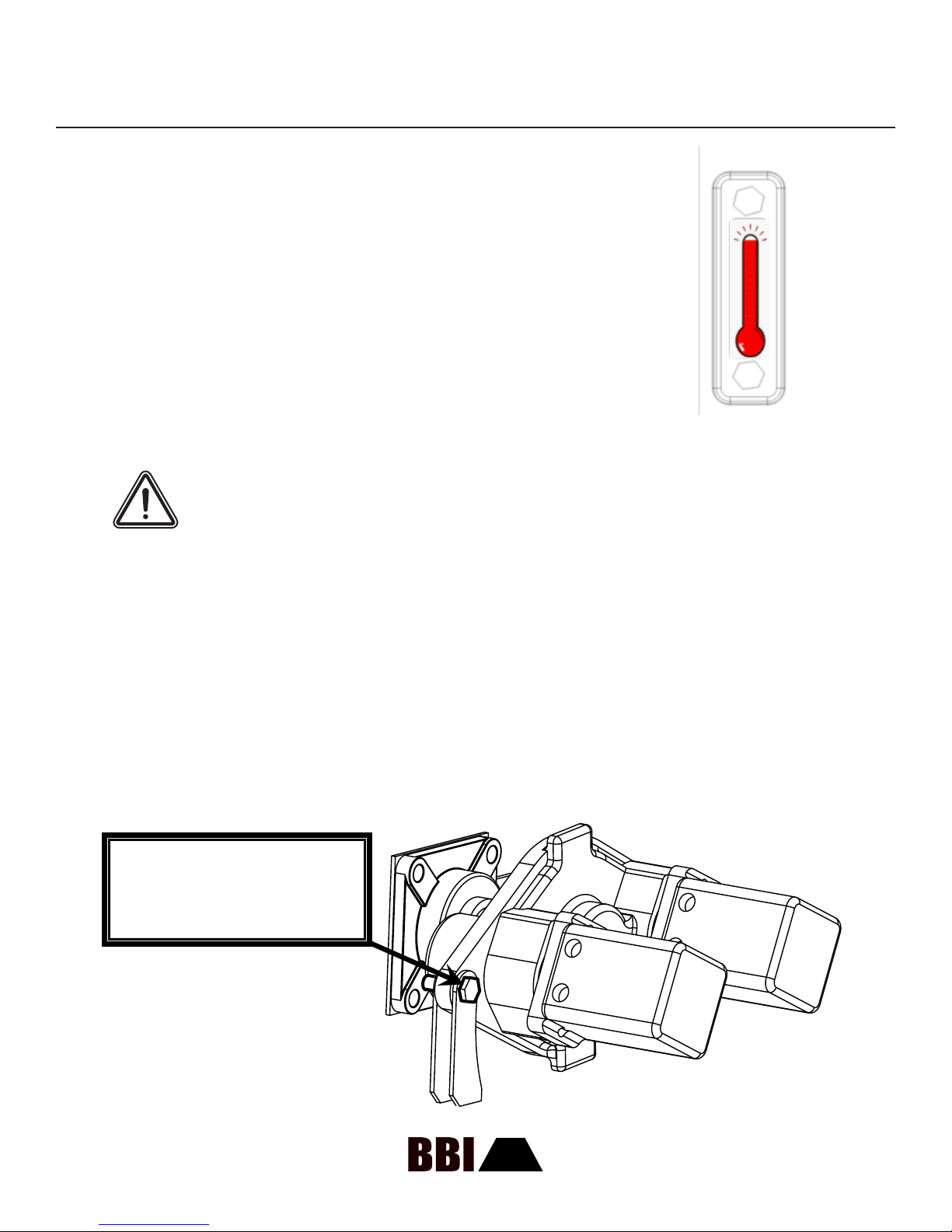
REMOVING THE CONVEYOR GEAR CASE
You must remove a bolt keeping the gear case from moving prior to taking the gear case off the rear roller
shaft. There is nothing else holding the gear case to the shaft except for this single bolt.
If the gear case is difcult to remove, then the key inside the gear case may have deformed due to
excessive torque. You can split the gear case housing to access the inside.
The seal (part #70601350) is easily damaged by this procedure. Remove and replace with caution.
THIS BOLT IS THE ONLY THING
HOLDING THE GEAR CASE ON
THE ROLLER SHAFT
29

PARTS AND SHIPPING
MagnaSpread Pull-Type
REPLACEMENT PARTS
Use only genuine BBI Parts.
Order parts from the authorized BBI dealer in your area.
When placing an order, please have available:
1. The model and serial number of the spreader.
2. The part name, part number, and the quantity required.
3. The correct street address for parts delivery, and your preferred carrier (if necessary)
DEALER’S PARTS DEPARTMENT INFORMATION:
Dealer Parts Representative:
Phone number:
Email:
SHIPPING DAMAGE
You must make claims for shortages and/or errors immediately upon receipt of goods from BBI.
When you receive broken or damaged goods, you must make a full description of the damage
to the carrier agent on the freight bill. If insisted upon, you can always collect full damage from
the transportation company. Please contact BBI as soon as possible after you have notied the
carrier.
If the transportation company is not handling your claims to your full satisfaction, please contact
BBI’s Customer Service Department at 1-800-282-3570 for assistance.
30

PARTS IDENTIFICATION AND ORDERING
MagnaSpread Pull-Type
Serial number is located here - it is comprised of
4 digits. Please have this number available when
Serial number is located here - it is comprised of
4 Digits. Please have this number available when
ordering equipment.
ordering replacement parts.
PARTS INFORMATION
Information contained in this section is provided for identication and reference purposes when
ordering replacement parts.
1). Identify the part or component that needs to be replaced.
2). Locate the appropriate section on the following pages where the part is located.
3). Reference the appropriate page to gather necessary part number and pertinent information.
REPLACEMENT PARTS ORDERING:
You have several options when ordering replacement parts:
1) Call your service dealer
2) Order through BBI’s parts website: www.bbispreaders.com
31

ASSEMBLY IDENTIFICATION
MagnaSpread Pull-Type
COMPONENT / ASSEMBLY IDENTIFICATION:
D. Hydraulic Tank / Reservoir
C. Binary Manifold
J. Gate Components
B. PTO Shafts
Input Shaft
Pump
A. Hitch
Jacks
E. Front Roller
Rear Roller
Chain
A: HITCH COMPONENTS
F. Hubs
Spindles
Tires
1
I. Hydraulic Motors
H. Spinners
Fins
Flow Divider
Shafts
Bearings
G. Tandem Gearcase
3
ITEM PART NO. DESCRIPTION QTY
1. 24PPHB305 Hitch Bracket 1
2. 24PPI208VR Perfect Hitch Clevis 1
3. 24PPI401V3 Perfect Hitch Pintle 1
4. 24P Hitchbolt Grade 8 Bolt 2
5. 24PPI401V3A Perfect Hitch Assembly 1
6. 24H20078 Heavy Duty Hitch 1
ITEM PART NO. DESCRIPTION QTY
1. 24SWL190DL 7K Jack 1
2. 24182304 10K Jack 1
2
32

ASSEMBLY IDENTIFICATION
MagnaSpread Pull-Type
B: PTO SHAFTS, INPUT COMPONENTS, PUMP
3
2
5
6
ITEM PART NO. DESCRIPTION QTY
1. 45HS18 18” Hydraulic Input Shaft 1/4 Key 1
2. 60HCFS206-20 1 1/4” Eccentric Roller Bearing 1
3. 15PTO-1-13 PTO Tower 1
U-Joint
4. 616400101500
5. 3025RM2525
6. 15PTO-H2A Shaft Guard 1
1 1/4” Round x 1/4” Key x
5/16” Key
Remote Mount Pump
*See separate diagram for seals,
keys, and gear sets.
4
1
1
1
ITEM PART NO. DESCRIPTION QTY
7. 64PTOS61000CV20
8. 64PTOS61000CV21
(Big 1000) 1 3/4” 20 Spline
constant velocity PTO shaft
(Small 1000) 1 3/8” 21 Spline
constant velocity PTO shaft
1
1
33

ASSEMBLY IDENTIFICATION
MagnaSpread Pull-Type
C: BINARY MANIFOLD COMPONENTS
3
4
0335-05013 cartridge
w/Kit 0390-02558
for spreaders with
BBI Binary Manifold
6
7
5
2
8
1
ITEM PART NO. DESCRIPTION QTY
1. 34PDSSIP210B Pressure Gauge 1
2A. 32GRVCOIL 32 GRV Coil 1
2B. 32GRVCARTRIDGE 32 GRV Cartridge 1
3A. 32ICBVPVS Dump Coil 1
3B. 32ICBVDVC Cartridge 1
4. 32JIAI25WN Spinner Flow Control 1
5. 32J06A2WN Chain Flow Control 1
6. 32RAH101530 Spinner Relief Valve 1
7. 32A04H3H2N Conveyor Relief Valve 1
8. 033505013 Servo Valve 1
34

ASSEMBLY IDENTIFICATION
MagnaSpread Pull-Type
D: HYDRAULIC RESERVOIR COMPONENTS
3
4
2
1
5
6
ITEM PART NO. DESCRIPTION QTY
1. 37HTP40 Tank 1
2. 34HC12012A Breather Cap 1
3. 34707782A Filter Head 1
4. 34702784A Filter 1
5. 34HSG-55 Sight Gauge 1
6. 32BV-125 Ball Valve 2
35

ASSEMBLY IDENTIFICATION
MagnaSpread Pull-Type
E1: FRONT ROLLER COMPONENTS
3
1
2
ITEM PART NO. DESCRIPTION QTY
1. 60UCF208-24 1 1/2” 4-Bolt Flange 2
2A. 42 FRAZ Adjusting Screw (Stainless) 2
2B. 42 FRAZ Adjusting Screw (Zinc) 2
3. 42 FRM20 Front Roller 1
36

ASSEMBLY IDENTIFICATION
MagnaSpread Pull-Type
E2: REAR ROLLER COMPONENTS
4
2
3
ITEM PART NO. DESCRIPTION QTY
1. 60UCF211-32 2” Flange Bearing 2
2. 89 POLYSQUARES Poly Squares 6.5 x 6.5 2
3. 42 RRM20HP Rear Roller 1
4. 42 C20 UHMW Comb 20” 1
CHAIN
41 MC 1120 - 20” Stainless Mesh Chain
41 MC 20SP - 20” Connector Pin
*Note: When ordering chain, please have serial number available.
To calculate the required length, multiply hopper length by two, then add two feet.
1
37
ASSEMBLY IDENTIFICATION
MagnaSpread Pull-Type
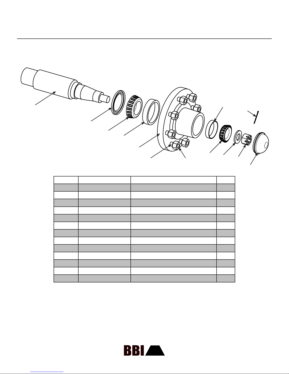
F: 10,000 LB (10K) HUB ASSEMBLY
22AX3160424A (8 BOLT)
1
8
13
2
3
4
5
9
6
7
10
11
12
ITEM PART NO. DESCRIPTION QTY
1. 22AXS-6000F 10K Spindle Shaft 1
2. 22AXSL-275 10K Oil Seal (CR27394) 1
3. 22AX506849 10K Inner Bearing 1
4. 22AX506810X 10K Inner Race 1
5. 22AX3160424 10K 8 Lug Hub Only 1
6. 22AXST-625 5/8” x 18-90 Press-in Stud 1
7. 22AXSTN-629 5/8” x 18-90 Lug Nut 1
8. 22AX501310 10K Outer Race 1
9. 22AX501349 10K Outer Bearing 1
10. 22AXSW-1001 10K Axle Washer 1
11. 22AXSN-1001 10K Axle Nut 1
12. 22AX1609 10K Dust Cap 1
13. 22AXSCP-102 10K Cotter Pin 1
38

ASSEMBLY IDENTIFICATION
MagnaSpread Pull-Type
F: 12,000 LB (12K) HUB ASSEMBLY
22AXBF2891300A (10 BOLT)
1
8
13
2
3
4
5
9
6
7
10
11
12
ITEM PART NO. DESCRIPTION QTY
1. 22AXBB281309 12K Spindle Shaft 1
2. 22AXBB906497 12K Oil Seal 2 1
3. 22AXBB910333 12K Inner Bearing 1
4. 22AXBB910331 12K Inner Race 1
5. 22AXBF2891300 12K 10 Lug Hub Only 1
6. 22AXBB13564 12K Press in Stud 1
7. 22AXBB913571 12K Flanged Nut 1
8. 22AXBB910332 12K Outer Race 1
9. 22AXBB910334 12K Outer Bearing 1
10. 22AXBB913632 12K Axle Washer 1
11. 22AXBB913571 12K Axle Nut 1
12. 22AXBB909983 12K Dust Cap 1
13. 22AXSCP-103 12K Cotter Pin 1
39

ASSEMBLY IDENTIFICATION
MagnaSpread Pull-Type
F: TIRES
MagnaSpread Tires 16.5” 8 Bolt 21.5” 8 Bolt 21.5” 10 Bolt 560 710 11.25” 18.4”
Suspension
8’ Single Axle Standard
10’ Single Axle Option Option
10’ - 12’ Tandem Axle Standard Option Option Option
14’ - 16’ Tandem Axle Standard Option Standard
Rigid Axle
(RA) / 9 Ton
9 Ton / 10
Ton
RA / 10T / 14T 14 Ton 20 Ton RA RA
*Most common packages are listed above
*Proper identication can be made through calling the factory with your product serial number
40

ASSEMBLY IDENTIFICATION
MagnaSpread Pull-Type
G: TANDEM GEARCASE WITH AND WITHOUT SENSOR
12
5
10
8
3
9
13
7
4
6
11
2
15
3
14
ITEM PART NO. DESCRIPTION QTY
1. 70301505 Key and Plug Kit (Key and 3 Plugs) 1
2. 70311062 Washer 1
3. 70313077 Pinion Gear 2
4. 70313084 Drive Gear (67 teeth) 1
5. 70315052 Tandem Inboard Housing 1
6. 70315090 Tandem Outboard Housing with Sensor (LH) 1
70315082 Tandem Outboard Housing without Sensor 1
7. 70601151 Bearing (Large 50 x 80 x 16mm) 4
8. 70601173 Small Output Bearing 2
9. 70601350 Oil Seal 1
10. 70611952 Tandem Gearcase Gasket 1
11. 70617006 Lock Washer 10
12. 70620041 Capscrew 10
13. 70601360 Seal for Sensor 1
14. Plug (Purchase in Key and Plug Kit) 1
15. Center Fill Plug (Purchase in Key Kit) 1
41

ASSEMBLY IDENTIFICATION
MagnaSpread Pull-Type
H: SPINNER SYSTEM COMPONENTS (1 OF 2)
1
2
3
4
5
6
7
8
9
ITEM PART NO. DESCRIPTION QTY
1. 3121SDM25 2.5” Motor 2
31M2100SK152025 Seal Kit 1
Seal Installation Tool. Required to
30Q1956-4
2. 61U183010293 U-Joint 2
3. 45FHMS28 Shaft 2
4A. 51SG-C Guard Rail (Carbon) 1
4B. 51SG-S Guard Rail (Stainless) 1
Carbon Stainless
51FT75MC-R Carbon 7.5” Right 51FT75MS-R Stainless 7.5” Right
51FT75MC-L Carbon 7.5” Left 51FT75MS-L Stainless 7.5” Left
51FT9MC-R Carbon 9” Right 51FT9MS-R Stainless 9” Right
51FT9MC-L Carbon 9” Left 51FT9MS-L Stainless 9” Left
properly install new motor pressure
seal.
5. FINS
1
Carbon Stainless
50MS24CSA-RH Carbon 24” Right 50MS24SSA-RH Stainless 24” Right
50MS24CSA-LH Carbon 24” Left 50MS24SSA-LH Stainless 24” Left
6. DISC ASSEMBLIES
42

ASSEMBLY IDENTIFICATION
MagnaSpread Pull-Type
H: SPINNER SYSTEM COMPONENTS (2 OF 2)
10
7
8
9
ITEM PART NO. DESCRIPTION QTY
7. 60UCP207-20 1 1/4” Pillow Block 2
8. 58HP1B-FT Hub 2
9. 50P1125 1 1/4” Locking Hub 2
ITEM PART NO. DESCRIPTION QTY
10. 52FFD200MS Flow Divider 1
FLOW DIVIDER COMPONENTS
18FD-MSI-C Insert 1
52TFD-1 Teon Block 1
60UCFL202-10 5/8” Bearing 1
52FDH Flow Divider Handle 1
43

ASSEMBLY IDENTIFICATION
MagnaSpread Pull-Type
I: HYDRAULIC MOTORS
SPINNER MOTORS
Motor Part# 3121SDM25
Seal Kit Part# 31M2100SK152025
Seal Installation Tool Part# 30Q1956-4 **This tool is required to properly install the double lip,
high-pressure seal included with the motor seal kit.
Please note that a complete exploded view diagram of the spinner motor is included in this
section as well. It should be referenced for proper assembly / disassembly of the spinner
motors and used to order other components..
CONVEYOR / BED CHAIN DRIVE MOTORS
Motor Part# 31BMRS200H2KS
Seal Kit Part# 31BMRS Seal Kit
HOSES
You can nd hydraulic hoses locally
44

MagnaSpread Pull-Type
SPINNER MOTOR
ASSEMBLY IDENTIFICATION
ITEM PART NO. DESCRIPTION QTY
1. 25527TCG Grease Seal 1
2. W023-206 Snap Ring 1
3. MZ-0961 Tell-Tale Seal Retainer 1
4. K-2995-109 Seal Retainer O-Ring 1
5. W62-49-9 Shaft Seal 1
6. 1/8” NPT Grease Fitting Hole
7. 2-Bolt-B Shaft End Cover (SEC) 1
8. W0-17 Pipe Plug 1/4” NPT for (SEC) 1
9. L-0280-K Check Valve Assembly 2
10. KA-0558-1XS Ring Seal 2
11. X-0921 Roller Bearing 4
12. ZZ-0947-TC Thrust Plate 2
13. K-2995-240 Gear Housing Gasket Seal 2
14. Gear Housing 1
15. 280-1971-031 Dowel Pin 4
16. W09-02 Shaft Key 1
17. Gear Set 1
18. 592-00662 Port End Cover (PEC) 1
19. W033-3 Washer 9/16” 4
20. Hex Head Bolt 4
45

ASSEMBLY IDENTIFICATION
MagnaSpread Pull-Type
REMOTE MOUNT PUMP (1 OF 2)
46

ASSEMBLY IDENTIFICATION
MagnaSpread Pull-Type
REMOTE MOUNT PUMP (2 OF 2)
ITEM PART NO. DESCRIPTION QTY
1. V-0961 Retainer Ring 1
2. W09-27 Shaft Key 1
3. QA-0024 Shaft 1 1/4” Dia. Keyed 1
4. RZ-0558 Seal Retainer 1
5. W62-26-13 Pump Shaft Seal 1
6. K-2995-26 O-Ring 1
7 & 8. W015-7 Taper Bearing 1
9. XZ-0558-1 Shaft Spacer 1
10. W86-100 Snap Ring 1
11. RZ-0575-3 Type 1 Pad Mount (SEC) 1
12. L-0280-K Check Valve 2
13. ZG-1909 Shaft Bushing 1
14. Z-0216-182 Spring 1
15. R-0921 Roller Bearing 8
16. X-0947-TC Thrust Plate 4
17. TA-2995-244 Gear Housing Gasket Seal 4
18. LZ-0577-25-5 Gear Housing 2 1/2” 1
19 & 20. JZ-0996L-25 Gear Set 2 1/2” 1
21. SZ-0408-9 Gear Spacer 2 1/8” 1
22. W004-19 Roll Pin 2
23. ZQ-1909 Shaft Bushing Slotted 2
24. JA-0576 Bearing Carrier (BC) 1
25. SZ-0022 Connecting Shaft 1
26. SZ-0408-9 Gear Spacer 2 1/8” 1
27. 3/8”-16 Threaded Rod 1
28. W78-05 Lock Nut 1
29. LZ-0577-25-5 Gear Housing 2 1/2” 1
30 & 31. JZ-0996L-25 Gear Set 2 1/2” 1
32. QZ-0592 Port End Cover (PEC) 1
33. W033-2 Washer 5/8” 4
34. ZD-0391-125 Tie Bolt 12 1/2” 2
35. ZD-0391-142 Tie Bolt 14 1/4” 2
36. W3-65 Hex Nut 5/8” - 11 4
47

MagnaSpread Pull-Type
J. GATE COMPONENTS
ASSEMBLY IDENTIFICATION
6
5
3
4
1
2
ITEM PART NO. DESCRIPTION QTY
1. 53GWB-7 Gate Wheel 1
2. 53GS Gate Slide (Stainless) 2
3. 53GSS Gate Shaft (Stainless) 1
4. 53GWS-2 Spur Gear 1
5. 53RG-2 Gate (Stainless) 1
6. 53GWS-3 Gear Rack 2
7. 53GGFT Gate Gauge 1
8. 53RG-15 Gate with Gear Rack 1
48

GROUND SPEED TABLES AND RATE CHARTS
MagnaSpread Pull-Type
GROUND SPEED TABLES
To use the tables and charts follow
these steps.
LOW APPLICATION
1. Choose the Ground Speed
Table that corresponds to the
preferred Rate Chart. (Low or High
Application)
2. Make sure the Rate Chart
corresponds to the swath width; And
size and type of conveyor chain, i.e.
20” Mesh.
3. Determine ground speed for
spreading.
4. Set Rear Roller RPM’s
according to the Ground Speed
Table by adjusting the conveyor
speed.
5. Set Gate Height according to
Rate Chart.
Rear Roller RPM = Ground Speed
Speed (MPH) Rear Roller RPM
4 = 4
5 = 5
6 = 6
7 = 7
8 = 8
9 = 9
10 = 10
11 = 11
12 = 12
13 = 13
14 = 14
HIGH APPLICATION
Rear Roller RPM = Ground Speed X 5
Speed (MPH) Rear Roller RPM
4 = 20
5 = 25
6 = 30
7 = 35
8 = 40
9 = 45
10 = 50
11 = 55
12 = 60
13 = 65
14 = 70
49

GROUND SPEED TABLES AND RATE CHARTS
MagnaSpread Pull-Type
18” MESH CHAIN RATE CHART
50

GROUND SPEED TABLES AND RATE CHARTS
MagnaSpread Pull-Type
20” MESH CHAIN RATE CHART
51

GROUND SPEED TABLES AND RATE CHARTS
MagnaSpread Pull-Type
20” BAR CHAIN RATE CHART
52

GROUND SPEED TABLES AND RATE CHARTS
MagnaSpread Pull-Type
24” BAR CHAIN RATE CHART
53

MagnaSpread Pull-Type
NOTES
54
 Loading...