

BBE Sound MOVISTROB 600-2GS, MOVISTROB 600-2GS-19 Instruction Manual
INSTRUCTION MANUAL
MOVISTROB® Series 600
High-power Stroboscope
Type 600.00 - 2GS - 19“
BBE Bamberg + Bormann - Electronic GmbH.
Wiebelsheidestraße 45
D-59757 Arnsberg / Neheim-Hüsten
Tel.: 0049 (0)2932-547760
Fax: 0049 (0)2932-34675
Internet: http://www.bbe-electronic.de
e-mail: info@bbe-electronic.de

1.
Introduction
Each MOVISTROB® product has to pass through various controls during its production phases
and must also undergo very strict and conscientious function and quality tests before leaving the
factory for delivery to our clients.
We can assure you that the MOVISTROB® product you received is in strict conformity with our
high quality standards and it fully meets all safety and performance requirements.
All relevant data on this instrument are electronically stored and can be recalled at any time.
Upon delivery, the instrument complies with the required safety regulations.
To maintain this condition and to ensure safe operation, it is absolutely essential to follow
the instructions below.
Advice
We therefore highly recommend to study the following Operating Instructions very thoroughly prior to
first use of the stroboscope. Besides technical informations the instructions contain also important hints
for use and application as well as special cautions against damage or injury.
Please note that we feel not responsible for any kind of damages or defects caused to the instrument
by inapprobiate handling or operation nor in case of unauthorized electronical or mechanical actions or
any kind of alterations to the unit.
2.
General Description
A stroboscope is used for studying rapid periodic motions. For this purpose, it generates short
flashes of light with a frequency corresponding to that of the motion of the viewed object.
In this way, the motion can be made to appear to slow down or stop and therefore visible.
This is possible, because the human eye is unable to distinguish the timing of interval images
above a certain frequency.
It is similarly possible to photograph linear motions viewed by the light of the stroboscope.
A further and important application in addition to this stroboscopic retarded action is the
measurement of speed. It is possible to measure the speed of small motors without loading
them mechanically, as it would be the case with measurement using a tachometer for example.
Our MOVISTROB® model 600-2GS-19 offers several advantages:
Extremely high light intensity for observation of large areas
- Long term time and temperature stability of the generated flash frequency.
- High accuracy and high time resolution
- Easy to handle due to colour signal push buttons
- Low maintenance costs
- Compact design
Easy operation is therefore ensured, even after extended periods of non - use.
MOVISTROB® model 600-2GS is an IC/CMOS-controlled, multi-functional high-power precision instrument.
The MS 600-2GS-19 high-output stroboscope consists of 2 components:
1. Control Unit containing the AC and generator sections as well as all operating controls.
2. Flahlamp equipped with an easy-to-replace, linear, high-output Xenon flash tube,
ON/OFF snap switch for the flash, swivel yoke.
Because of the extremely high light output of the quartz lamp, the unit is especially suited for illuminating
oversized objects such as printing presses, rolling mills, looms, large blowers and fans, and other machines used
in aircraft construction, shipbuilding, textiles, ect.
The unit can also be effectively used as a light source for high-speed photography, allowing fast non-periodic
motion, such as crash and drop tests, to be captured on film.
In addition to adjusting the flash frequency with the 10-stage helical potentiometer on the control box (internal)
after preselection of the flahfrequency, you can also control the flash frequency externally. You can activate
external triggering with a contact switch, current impulse or light impulse from a compatible source. During
external triggering, an absolutely stopped image of the object results even when the frequency of the periodic
motion fluctuates. This mode of operation also provides digital readout of the controlled flash frequency. A
phase-shift control knob allows a timed-pulse delay of up to 330°, by which motion can also be observed during
external triggering in any desired motion phase.
If you desire to study line-synchronous cycles, such as slip measurements, you can control the unit directly
through the line frequency by pressing the „LINE“ button switch. You can also use the phase-shift control knob
to change the phase position in this mode.

The flash rate is continuously adjustable from 120 to 19200 flashes/minute, equivalent to 2 to 320 Hz.
The average flash duration is about 15 µs. The unit offers a wide variety of features in a very compact
sheet steel housing (w=434/477 x h=177 x d=231 mm).
CAUTION!
Persons with limited physical, sensorial or mental abilities are not allowed to use the unit,
unless they are supervised for their safety by a qualified person or are briefed by the
responsible person how to use the unit.
Use of this product may induce an epileptic seizure in those prone to this type of attack.
Objects viewed with this product may appear to be stationary when in fact they are moving
at high speeds.
Always keep a safe distance from and do not touch the target.
There are high voltages present inside this product. Refer to the section on lamp replacement
before attempting to open this product.
Do not allow liquids or metallic objects to enter the ventilation holes on the stroboscope
as this may cause permanent damage.
The instrument may be operated by trained personnel only.
Maintenance and repairs may also be carried out by qualified personnel or by the manufacturers only.
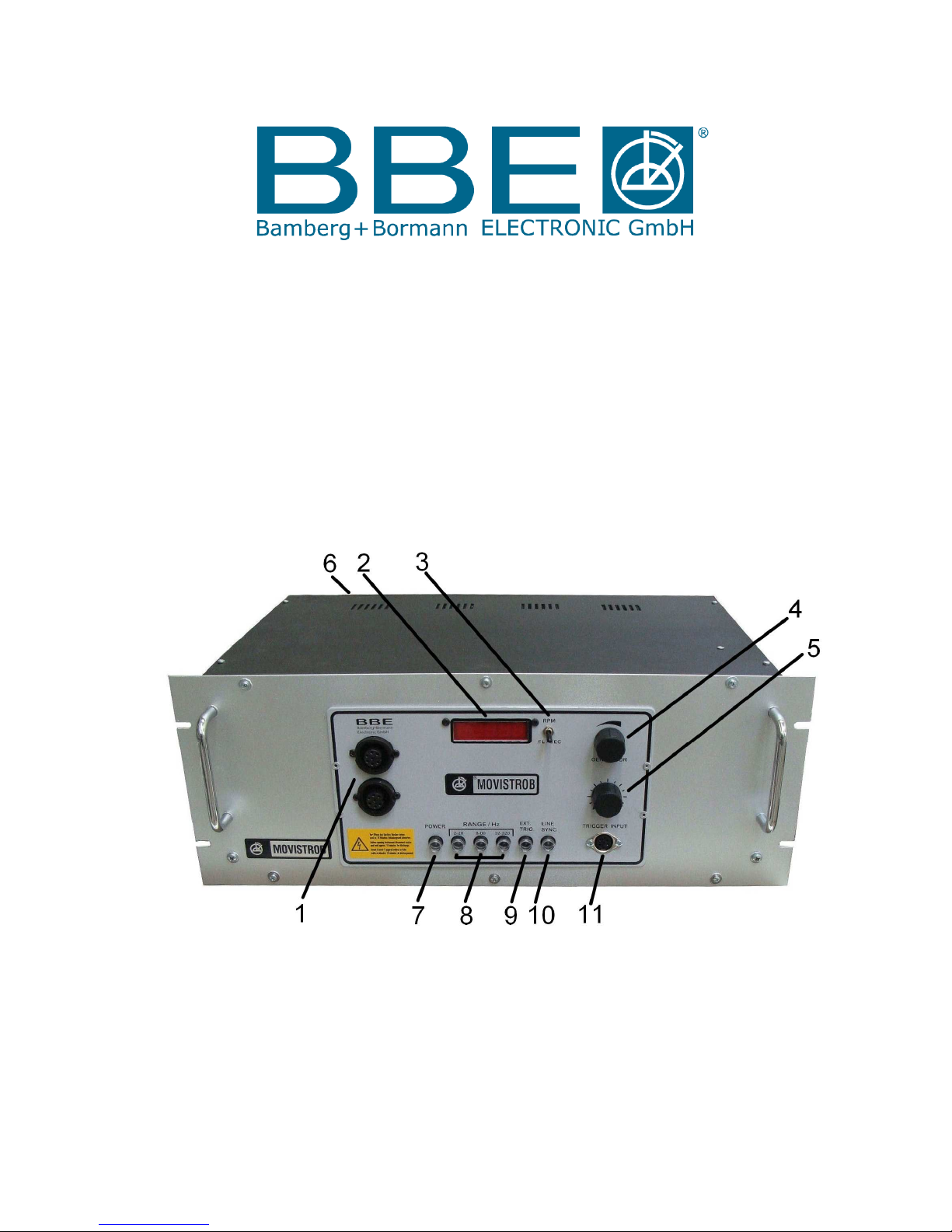
3. Controls and Indicators
Control Unit 600 – 2GS - 19
3.1 OUTPUT SOCKETS for Flashlamp GS / KS ( 1 )
The flashlamp with the appropriate cable must be connected with the output socket. Lock the
plug in place by screwing the collar on the plug to the thread of the output socket.
Note:
The flashlamp must be connected to the control unit before switch-on.
When disconnecting the flashlamp the power pushbutton ( 7 ) must be reset in initial position "OFF"
(black colour signal).
3.2 DISPLAY WINDOW ( 2 )
Within the frame of the display window inserted in the control panel, the 5/16 (10 mm) high
7-segment LED numerals are easily readable. When readout in flashes per second = Hz is selected
a red decimal point appears automatically. Readout in Hz is carried out to 2 decimal places
3.3 SELECTOR SWITCH for RPM or FL/SEC (Hz) READOUT ( 3 )
The measuring time is 1 second in a measuring sequence of 2 seconds. The measuring accuracy is
based on quartz time and amounts to ± 1 revolution on the RPM readout. The range of error on the
"FL/SEC" readout (Hz) is only 1/100 ± digit.
3.4 ADJUSTMENT KNOB for INTERNAL FLASH FREQUENCY "GENERATOR" ( 4 )
for continuous adjustment of the internal flash frequency which is infinitely variable within the
frequency range preselected with the range selector pushbuttons ( 8 ). If you turn the adjustment
knob (10-stage helical potentiometer) clockwise, as shown by the curve symbol, the flash frequency
rises, when you turn it counterclockwise, it drops.
3.5 PHASE SHIFTER ( 5 )
Using the phase-shift control knob the flash phase position can be moved infinitely up to 330°
counter to the control impulses in external triggering or line-synchronous operation, allowing
observation of the test object in its various motion segments.
Change the phase position by turning the control knob in the direction of the curved symbol.
3.6
RECEPTACLE for AC POWER CABLE ( rear side - 6 )
The socket connects the control unit to AC power with the 2-meter (7 ft. approx.) cable.
 Loading...