

Page 1
INSTRUCTION MANUAL
MOVISTROB® Series 2100
Type MINISTROB 2155
BBE Bamberg + Bormann - Electronic GmbH
Wiebelsheidestraße 45
D-59757 Arnsberg / Neheim-Hüsten
Tel.: 0049 (0)2932-547760
Fax: 0049 (0)2932-34675
Internet: http://www.bbe-electronic.de
e-mail: [email protected]
Page 2

2
1. Introduction
Each MOVISTROB® product has to pass through various controls during its production phases and must also
undergo very strict and conscientious function and quality tests before leaving the factory for delivery to our clients.
We can assure you that the MOVISTROB® product you received is in strict conformity with our high quality
standards and it fully meets all safety and performance requirements.
All relevant data on this instrument are electronically stored and can be recalled at any time.
Upon delivery, the instrument complies with the required safety regulations. To maintain this condition and
to ensure safe operation, it is absolutely essential to follow the instructions below.
Advice
We therefore highly recommend to study the following Operating Instructions very thoroughly prior to first use
of the stroboscope. Besides technical informations the instructions contain also important hints for use and application
as well as special cautions against damage or injury.
Please note that we feel not responsible for any kind of damages or defects caused to the instrument by inapprobiate
handling or operation nor in case of unauthorized electronical or mechanical actions or alterations to the unit.
2. General Description and Application
The processor controlled small format MINISTROB type 2155 with 5 luminous digits, 7-segment LED-display is
equipped with Xenon flash tubes.
The Xenon flash bulb is a source of intermittent white light with high light intensity and long lifetime.
Its flash rate is continuously adjustable in the range from 60 to 19.800 flashes/min, corresponding to 1 to 330Hz.
The average flash duration is about 5 µs.
The flash frequency is controlled by quartz stabilization over the entire range to an accuracy of ± 1 revolution, or,
in case digital readout is set in Hz (flashes/sec), to 1/100 ± 1 digit (rounded off to two decimal places).
The display indicates the flash frequency even when controlled by external triggering.
The measuring time is 1 s for a measurement cycle of 2 s.
The stroboscope is housed in an unbreakable plastic case (195 x 110 x 75 mm). Owing to its small weight,
compact design and the neat arrangement of its controls, the unit can be easily carried and conveniently operated.
The instrument is provided with a 2 m long cord with safety plug for connection to the AC line.
The stroboscope is a combination of a high light intensity stroboscope and a digital frequency meter.
The instrument serves for the optical observation of fast periodic or quasi-periodic motions, such as moving parts
in machinery under certain operating conditions: e.g. rotating shafts, gear wheel blades, valves in operation etc.
The digital readout always shows the exact value measured, and eliminates the misreadings in case of analogue scales.
The flash frequency of the stroboscope can be adjusted infinitely and synchronised to the motion frequency of
the object under observation. This provides an optical slow motion effect to enable visual examination of mechanical
distortions or displacements at high motion speeds. Moreover, the stroboscope may be used to identify the number
of revolutions per minute or second of rotating parts.
By means of external triggering, irregularly occurring processes can also be examined.
The display indicates the flash frequency during this mode, too.
The external triggering can be activated by contact closing, voltage impulse, or light impulse with suitable equipment.
CAUTION!
Persons with limited physical, sensorial or mental abilities are not allowed to use the unit,
unless they are supervised for their safety by a qualified person or are briefed by the
responsible person how to use the unit.
Use of this product may induce an epileptic seizure in those prone to this type of attack.
Objects viewed with this product may appear to be staionary when in fact they are moving at high speeds.
Always keep a safe distance from and do not touch the target.
There are high voltages present inside this product. Refer to the section on lamp replacement before attempting
to open this product.
Do not allow liquids or metallic objects to enter the ventilation holes on the stroboscope as this may cause
permanent damage.
The instrument may be operated by trained personnel only. Maintenance and repairs may also be carried out
by qualified personnel or by the manufactureres only.
Page 3

3
3. Controls and Indicators
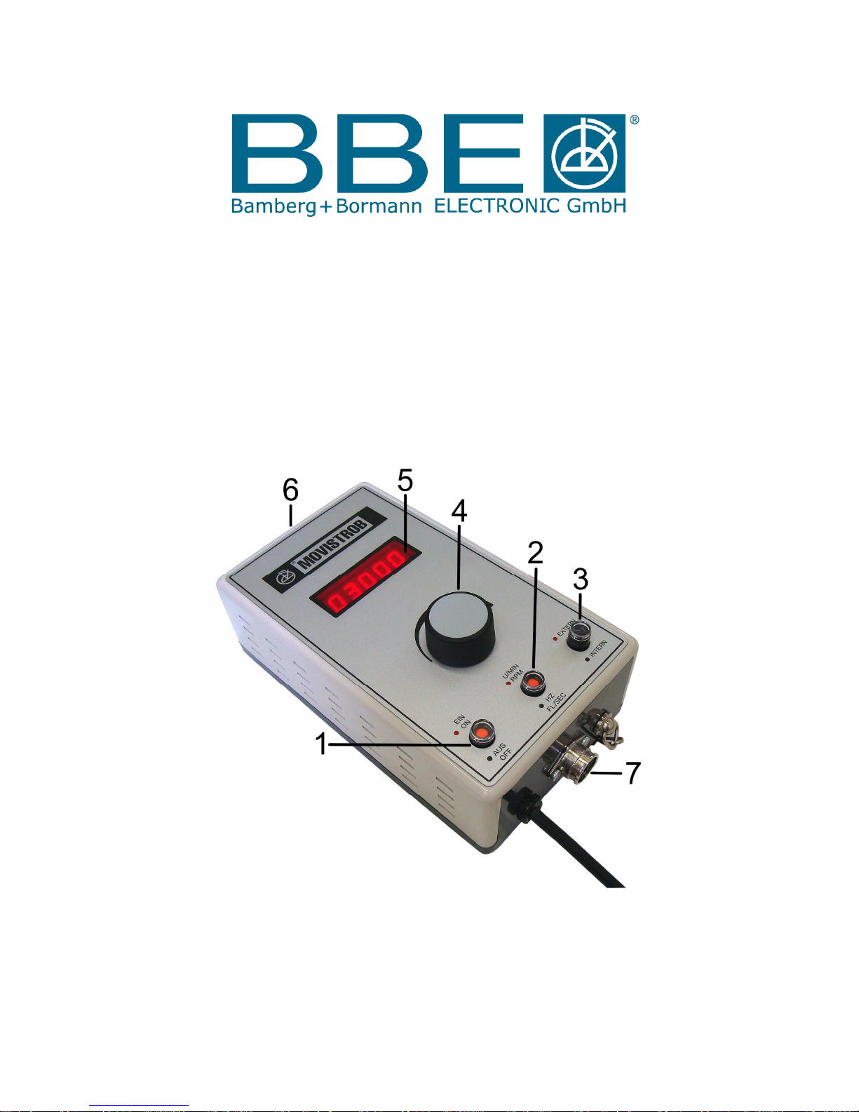
The instrument carries the following controls and functional components (see figure):
3.1 Signal Mains Pushbutton ( 1 )
Switches on the instrument by depressing the pushbutton,
Red signal appears when ready to work
3.2 Signal Readout Pushbutton ( 2 )
Depressed button (red signal) indicates the flash frequency per minute = RPM.
Unpressed button (black signal) produces the flash frequency per seconde = Hz.
(up to two decimal places).
3.3 Signal Mode Selector Pushbutton ( 3 )
Serves to select the desired mode of synchronization.
The button must be depressed (red signal) when the flash frequency is to be controlled
by an external source via "Trigger Input 3.7".
When the button is not depressed (black signal) the flash rate can be adjusted by means
of "Control Knob 3.4" ( Encoder ) within the selected range.
3.4 Control Knob for Flash Frequency Adjustement ( 4 )
for continuous fine adjustment of the flash frequency by means of the Encoder.
Turning the Control Knob in clockwise direction, indicated by a curve, increases the flash frequency.
The opposite direction lowers the flash rate. The Encoder enables the operator
to adjust the flash frequency very precisely.
Automatic Standby
If the control knob of the encoder has not been actuated or the flash frequency of the MINISTROB type 2155
stroboscope has not been changed for a period of approx. 5 minutes, standby will automatically be released in
order to protect the flash bulb. In this non-working mode the display indicates 5 red lines. However, the last
indicated value will be stored. By turning the control knob the instrument operates again starting up
with the last measured value.
3.5 Display Window ( 5 )
Within the frame of the display window inserted in the control panel, the 10 mm high 7-segment LED figures
are easily readable. When readout in flashes per second = Hz is selected a red decimal point appears
automatically. Readout in Hz is carried out to 2 decimal places.
3.6 Flash Bulb with Transparent Fibreglass Reflector Cover ( 6 )
The Xenon longlife gas discharge tube is mounted within a reflector which is protected by a transparent
fibreglass cover. Changing the transparent cover for a red filter cover type 2000.11, the fiberglass cover
can easily be removed by unscrewing the two screws holding the cover on the housing. The red filter
supplies a selective contrast to daylight and prevents the human eye from early stress and symptoms of
fatigue in case of longtime observations. However the red filter will definitely reduce the light intensity.
Within the selected frequency range the shape of the light pulses is virtually independent of the frequency;
however, when changing over from high to low range, the pulse amplitude and duration are increased to a
certain extent. Since the average pulse duration is only about 5 µs, the object will appear always sharply
defined at high speeds.
3.7 Input for External Control ( 7 )
Connection of an external source for controlling the flash rate (270° input socket), located on the narrow side
underneath the row of buttons.
Page 4
4
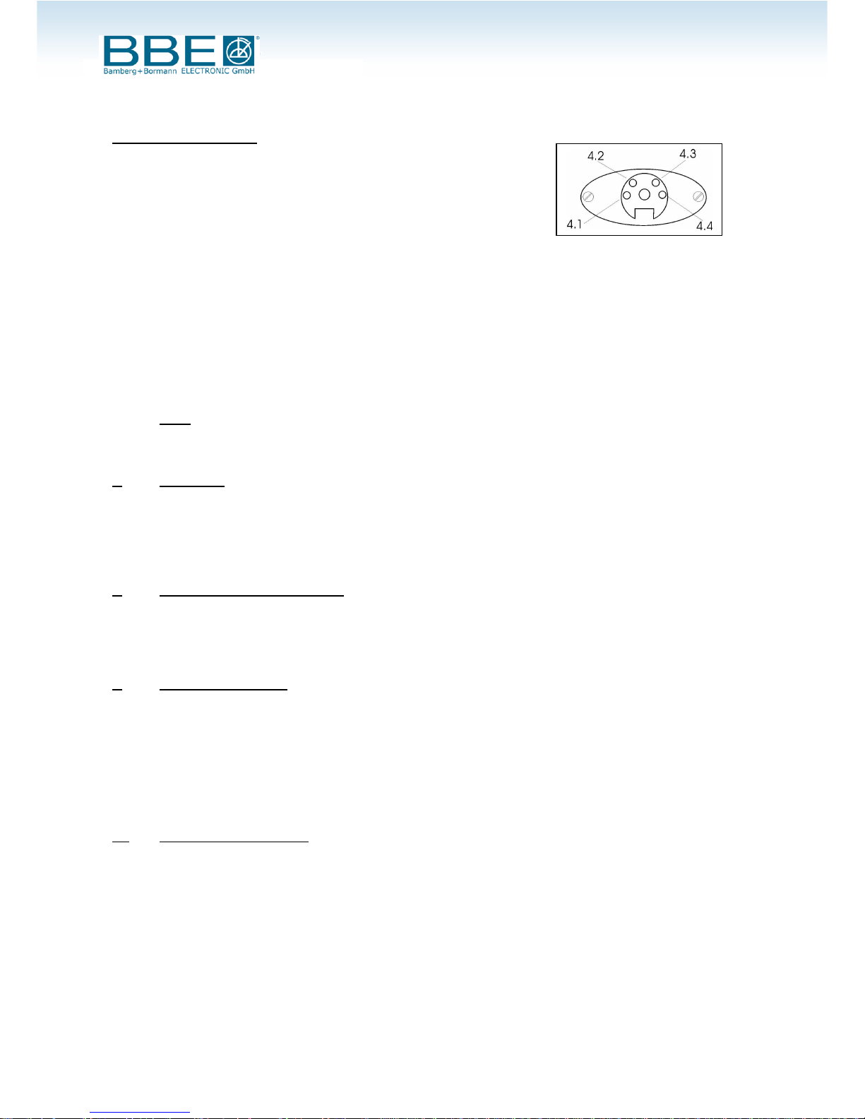
Contacts of Trigger Input:
Pole 4.1/4.2 = 15VDC / 4.1 Plus – 4.2 Gnd
Pole 4.3/4.4 = Input Triggerimpuls / 4.4 Plus – 4.3 Gnd
for connection of an electrical generator
within a range from 2.5V to 24V and for
connection of a closing contact.
Pole 4.2/4.3 are for connection of a closing contact
flash will be released on closing
Make sure that "Signal Mode Selector 3.3" is depressed (red signal) when flash frequency
is to be controlled by an external source.
When triggering via closing contacts, control circuit resistance should not exceed 1Kiloohm
when contacts are closed. Back-to-back operation is permissible. The short-circuit current is
under 10 mA, i.e. below the 30 mA allowable limit current. The power circuit may not contain
an external current source. When triggered by external current the flash is triggered along the
positively-directed edge of an impulse. The impulse current (maximum) should not exceed 24V.
The response cycle lies at 2,5 V (TTL).
Note:
In order to protect the flash bulb against demage an automatic cutoff will be activated as soon as the flash
frequency exceeds 330 Hz. However the display will continue indicating the trigger frequency.
4. Installation
Check whether the instrument is adapted to the nominal AC voltage as given on the type plate.
After switching on by pressing the signal pushbutton "3.1" it is instantly ready for operation.
Illuminate the object under test with the strobe and set the flash rate so that a stationary
or slowly moving object is visible.
5. Operation with Internal Control
The mode of operation mainly used is to control the flash rate by the internal frequency generator.
Make the adjustment within the selected range by turning control knob "3.4".
Readout per minute or seconde can be selected by push button "3.2".
6. Stroboscopic Principle
With stroboscopy, high-speed periodic motion which cannot be followed by unassisted eyes can be made accessible for
observation and its frequency measured. For this purpose the oscillating or rotating object is illuminated in a periodic
series of light impulses (flashes) which are as brief as possible. The object then appears (at the appropriate flash
frequency) to be motionless (stopped image) or slowed (slow-motion).
The object’s behavior and motion can thus be observed in all their details.
At low frequencies in the flash rate (below about 30 Hz) a certain flickering of the image is unavoidable.
To make the visual perception appear real requires a solid-colored disc with a single eccentric mark.
6.1 Stopped image of the object
If the rotating object (or the mark) is to appear to the observer as a stopped image under stroboscopic light,
the period T of the flash frequency must be a whole-number multiple n of the rotation period r:
T = Tn = nr
For the corresponding frequencies f = 1/T and revolutions v = 1/r the relationship is:
f = fn = 1 v ÷ n
The highest flash frequency (n = 1) which produces a stopped image of the object, i.e. the mark
equals the revolutions: f1 = v (stopped images in which the mark appears more than once still
result from flash frequency f > f1).
Page 5

5
The observed phase of the rotation in stopped image, i.e. the rotational angle at the moment of the flash,
is purely accidental. Through brief changes in of the flash frequency however the desired phase position
can be adjusted approximately. In the same way, RPM fluctuations can cause a change in phase position.
Exact phase stability, i.e. sharply stopped image, can be achieved when the flash frequency is controlled
externally by the moving object (does not apply for MINISTROB series 2000).
6.2 Measurement of RPM and frequencies
To measure the RPM v either the highest flash frequency f1 = v which results in a stopped image of the object
can be determined, or two neighbouring flash frequencies fn and fn+1 can be determined and from these
the rotational frequency computed. For the periods for f and fn+1 in the flash frequency the equation is:
r = Tn+1 - Tn
From this we derive the frequencies:
v = fn • fn+1 ÷ fn - fn+1
6.3 Slow-motion cycle
If the period T of the flash frequency deviates slightly from a whole-number multiple Tn = nr of the rotation
time r of the object, i.e.
T = (n + e) r with /e/ < 1
then the object no longer appears stopped, but has rotated through the angle 2e between two succeeding flashes.
If /e/ is sufficiently small the eye perceives a constant slow-motion cycle. Angular speed w’, at which the object
appears to rotate, is given by:
w’ = 2 v’ = 2 π e = 2 π e 2 π e
T (n+e) r nr
If we compare this with the true angular speed of the object, we obtain:
w’ = (e ÷ n ) • w
For e > 0 (i.e. T > Tn and/or f > fn) w and w’ have the same sign, so that true and apparent rotation are
in the same direction.
The opposite holds for e < 0. With increasing /e/ the angular speed w’ of the apparent rotation rises.
Finally the angle 2πe becomes so large that the mark on the rotating disc appears at two different places
during two succeeding flashes. Other phenomena (described below) also occur.
6.4 Stopped images of phantom objects
Stopped images of rotating objects results from flash frequency periods Tn = nr, and also at other flash frequencies.
However, the latter represent phantom objects, not the real object. Using the example of the rotating disc with an
eccentric mark , it is obvious that stopped images also occur when:
T = ( n ÷ k ) r and / or f = ( k ÷ n ) v,
whereby n and k are whole relatively-prime numbers. The stopped image shows k marks, which are arranged in the
corner of a regular k-angle. Only a very few of the theoretically infinite number of flash frequencies result in observable
images, since at each corner of the k-angle there is only one mark for k sequential flashes, but (k - 1) times no marks.
As k increases then the images have less and less contrast. The images of the real object (k =1) always appear sharpest.
In addition, the images become more and more faint at a given k with increasing n. The interval in which the mark
is illuminated at one corner of the k-angle amounts to n rotation periods. In conclusion , the k mark images must not
overlap. Altogether we may expect observable images only with low values of n and k.
In objects with a complicated texture the phantom objects mostly disappear in an untextured background.
Page 6

6
6.5 Objects with a finite rotational symmetry
In many cases the axis of the rotating object is an m-number symmetrical axis, i.e. the object overlaps itself
through a rotation about the angle 2/m. In the example of the disc this is achieved through m equal marks
which are arranged in the corners of a regular m-angle. In this case substitute r/n for the period r in the
relationships derived above.
Stopped images of the real object therefore result from
T = (n + k) r and /or f = (k + n) v,
In addition, stopped images of phantom objects also occur for
T = ( n ÷ k ) • ( r ÷ m ) and / or f = ( k ÷ n ) ( m • v )
(k, m, n are whole numbers). If k and n are selected relatively-prime, k.m marks appear in the corners of
a regular k.m-angle.
7. Replacing Flash Tube and Fuses
If there is repeated flash failure or complete breakdown, the tube must be replaced. For this purpose the transparent
plastic cover to protect the reflector must be removed by unscrewing the 2 screws. Before attempting to remove the
lamp make sure the stroboscope is turned off and any mains cord removed from the AC outlet. Allow the lamp to cool
but wait at least 5 minutes before attempting to change the lamp. The 3-pin tube must be gently pulled out. Insert the
new tube (incorrect insertion impossible) and, if necessary, remove fingerprints by means of a soft cloth. In case the
flash tube fits in very tight the cover of the housing has to be taken off by unscrewing four screws. Loosen the tube with
a screwdriver applied as a lever between tube base and socket and pull the tube out. Only after the housing has been
closed, should the instrument be put into operation again.
It may take up to one hour before a new tube produces an uninterrupted flash sequence.
Remark
Do not use the flash bulb needlessly, as its life is limited to approx. max. 2500 hrs. depending on conditions
of operation. You will achieve a much longer lifetime, if you switch the instrument off in cases of long intervals in
between the measuring or motion control actions.
After the cover of the plastic housing has been removed, the fuse (0.5 A for 230V AC and 0.63 A for 110 V AC unit) is
accessible and can be replaced.
8. Maintenance and Repair
If the instrument is suspected of being unsafe, take it out of operation permanently. This is usually the
case when the unit shows physical demage, no sign of functioning or stress beyond the tolerable limits.
Repair, replacing parts, calibration ect. should be carried out by trained personnel only or preferably
return it to the manufacturer for inspection and control.
In correspondence concerning the instrument, please quote the type number and serial number
as given on the type plate underneath the bottom of the housing.
Page 7

7
TECHNICAL Data
MINISTROB 2155
Supply voltage 220 - 230 V AC, 50 - 60 Hz
or 115 V AV, 50 - 60 Hz
Light source Xenon white light tube, 3-pin plug-in type
Peak light intensity approx. 450 lux
Flash duration approx. 2 - 6 µ-seconds
Frequency range 1 - 330 Hz or 60 - 19.800 RPM
Digital read-out 5-place 7-segment LED, red, 10 mm high
Read-out switching in Hz or RPM
Frequency fine tuning Encoder
Accuracy for RPM read-out: ± 2 RPM
for Hz read-out: ± 1/00 ± 1 digit
Measuring time 1 sec
Measuring cycle every 2 seconds
Control internal, contact switch, and pulse triggering
Casing shatterproof plastic
Dimensions 195 x 75 x 110 mm
weight 800 grs.
Arnsberg, 19.08.2014
Right of technical modification reserved
 Loading...