

BBE Sound MOVISTROB 2100, MOVISTROB 2155 Instruction Manual
INSTRUCTION MANUAL
MOVISTROB® Series 2100
Type MINISTROB 2155
BBE Bamberg + Bormann - Electronic GmbH
Wiebelsheidestraße 45
D-59757 Arnsberg / Neheim-Hüsten
Tel.: 0049 (0)2932-547760
Fax: 0049 (0)2932-34675
Internet: http://www.bbe-electronic.de
e-mail: info@bbe-electronic.de

2
1. Introduction
Each MOVISTROB® product has to pass through various controls during its production phases and must also
undergo very strict and conscientious function and quality tests before leaving the factory for delivery to our clients.
We can assure you that the MOVISTROB® product you received is in strict conformity with our high quality
standards and it fully meets all safety and performance requirements.
All relevant data on this instrument are electronically stored and can be recalled at any time.
Upon delivery, the instrument complies with the required safety regulations. To maintain this condition and
to ensure safe operation, it is absolutely essential to follow the instructions below.
Advice
We therefore highly recommend to study the following Operating Instructions very thoroughly prior to first use
of the stroboscope. Besides technical informations the instructions contain also important hints for use and application
as well as special cautions against damage or injury.
Please note that we feel not responsible for any kind of damages or defects caused to the instrument by inapprobiate
handling or operation nor in case of unauthorized electronical or mechanical actions or alterations to the unit.
2. General Description and Application
The processor controlled small format MINISTROB type 2155 with 5 luminous digits, 7-segment LED-display is
equipped with Xenon flash tubes.
The Xenon flash bulb is a source of intermittent white light with high light intensity and long lifetime.
Its flash rate is continuously adjustable in the range from 60 to 19.800 flashes/min, corresponding to 1 to 330Hz.
The average flash duration is about 5 µs.
The flash frequency is controlled by quartz stabilization over the entire range to an accuracy of ± 1 revolution, or,
in case digital readout is set in Hz (flashes/sec), to 1/100 ± 1 digit (rounded off to two decimal places).
The display indicates the flash frequency even when controlled by external triggering.
The measuring time is 1 s for a measurement cycle of 2 s.
The stroboscope is housed in an unbreakable plastic case (195 x 110 x 75 mm). Owing to its small weight,
compact design and the neat arrangement of its controls, the unit can be easily carried and conveniently operated.
The instrument is provided with a 2 m long cord with safety plug for connection to the AC line.
The stroboscope is a combination of a high light intensity stroboscope and a digital frequency meter.
The instrument serves for the optical observation of fast periodic or quasi-periodic motions, such as moving parts
in machinery under certain operating conditions: e.g. rotating shafts, gear wheel blades, valves in operation etc.
The digital readout always shows the exact value measured, and eliminates the misreadings in case of analogue scales.
The flash frequency of the stroboscope can be adjusted infinitely and synchronised to the motion frequency of
the object under observation. This provides an optical slow motion effect to enable visual examination of mechanical
distortions or displacements at high motion speeds. Moreover, the stroboscope may be used to identify the number
of revolutions per minute or second of rotating parts.
By means of external triggering, irregularly occurring processes can also be examined.
The display indicates the flash frequency during this mode, too.
The external triggering can be activated by contact closing, voltage impulse, or light impulse with suitable equipment.
CAUTION!
Persons with limited physical, sensorial or mental abilities are not allowed to use the unit,
unless they are supervised for their safety by a qualified person or are briefed by the
responsible person how to use the unit.
Use of this product may induce an epileptic seizure in those prone to this type of attack.
Objects viewed with this product may appear to be staionary when in fact they are moving at high speeds.
Always keep a safe distance from and do not touch the target.
There are high voltages present inside this product. Refer to the section on lamp replacement before attempting
to open this product.
Do not allow liquids or metallic objects to enter the ventilation holes on the stroboscope as this may cause
permanent damage.
The instrument may be operated by trained personnel only. Maintenance and repairs may also be carried out
by qualified personnel or by the manufactureres only.

3
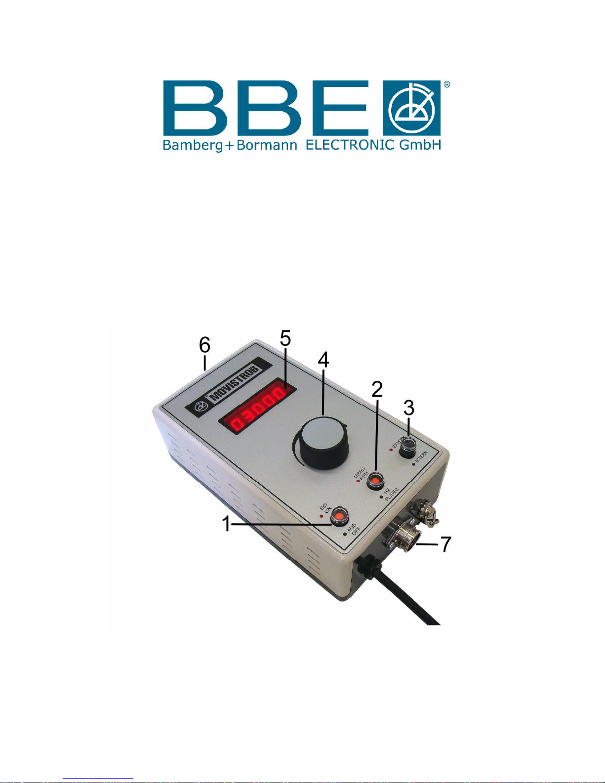
3. Controls and Indicators
The instrument carries the following controls and functional components (see figure):
3.1 Signal Mains Pushbutton ( 1 )
Switches on the instrument by depressing the pushbutton,
Red signal appears when ready to work
3.2 Signal Readout Pushbutton ( 2 )
Depressed button (red signal) indicates the flash frequency per minute = RPM.
Unpressed button (black signal) produces the flash frequency per seconde = Hz.
(up to two decimal places).
3.3 Signal Mode Selector Pushbutton ( 3 )
Serves to select the desired mode of synchronization.
The button must be depressed (red signal) when the flash frequency is to be controlled
by an external source via "Trigger Input 3.7".
When the button is not depressed (black signal) the flash rate can be adjusted by means
of "Control Knob 3.4" ( Encoder ) within the selected range.
3.4 Control Knob for Flash Frequency Adjustement ( 4 )
for continuous fine adjustment of the flash frequency by means of the Encoder.
Turning the Control Knob in clockwise direction, indicated by a curve, increases the flash frequency.
The opposite direction lowers the flash rate. The Encoder enables the operator
to adjust the flash frequency very precisely.
Automatic Standby
If the control knob of the encoder has not been actuated or the flash frequency of the MINISTROB type 2155
stroboscope has not been changed for a period of approx. 5 minutes, standby will automatically be released in
order to protect the flash bulb. In this non-working mode the display indicates 5 red lines. However, the last
indicated value will be stored. By turning the control knob the instrument operates again starting up
with the last measured value.
3.5 Display Window ( 5 )
Within the frame of the display window inserted in the control panel, the 10 mm high 7-segment LED figures
are easily readable. When readout in flashes per second = Hz is selected a red decimal point appears
automatically. Readout in Hz is carried out to 2 decimal places.
3.6 Flash Bulb with Transparent Fibreglass Reflector Cover ( 6 )
The Xenon longlife gas discharge tube is mounted within a reflector which is protected by a transparent
fibreglass cover. Changing the transparent cover for a red filter cover type 2000.11, the fiberglass cover
can easily be removed by unscrewing the two screws holding the cover on the housing. The red filter
supplies a selective contrast to daylight and prevents the human eye from early stress and symptoms of
fatigue in case of longtime observations. However the red filter will definitely reduce the light intensity.
Within the selected frequency range the shape of the light pulses is virtually independent of the frequency;
however, when changing over from high to low range, the pulse amplitude and duration are increased to a
certain extent. Since the average pulse duration is only about 5 µs, the object will appear always sharply
defined at high speeds.
3.7 Input for External Control ( 7 )
Connection of an external source for controlling the flash rate (270° input socket), located on the narrow side
underneath the row of buttons.
 Loading...