

Page 1
MMooddbbuuss MMooddee
CChheecckk ffoorr AAllll RReeqquuiirreedd HHaarrddwwaarree
SSeelleecctt MMoodduulleess
HHaarrddwwaarree IInnssttaallllaattiioonn
CCoonnnneecctt FFiieelldd WWiirriinng
g
IInnssttaallll ZZlliinnxx II//OO SSooffttwwaarre
e
1
3
2
5
4
Quick Start Guide
Zlinx™ I/O
5
Zlinx I/O Base Module and Expansion Modules
ZZ-PROG1 Configuration Box or ZZ-PROG1-USB
Module
Straight-through serial cable or USB cable if using
a ZZ-PROG1-USB Module
This Quick Start Guide
Zlinx Wireless Modbus I/O Manual on CD (Can be
downloaded from the Web Site)
Zlinx I/O Manager software on CD (Can be downloaded
from the Web Site)
Special Precautions for UL and UL Class I DIV 2 (C1D2)
Note 1: Class 1, Div 2 is NOT applicable to ZZxD-Nx-MR (medium range),
ZZ8D-Nx-xR (800 MHz) and ZZxD-Nx-xR-AU (Australian) modules.
Note 2: For C1D2 information on ZZ-8DO-R, separate sheet is attached.
WARNING – EXPLOSION HAZARD – SUBSTITUTION OF COMPONENTS
MAY IMPAIR SUITABILITY FOR CLASS I, DIVISION 2.
WARNING – EXPLOSION HAZARD – WHEN IN HAZARDOUS LOCATIONS,
TURN OFF POWER BEFORE REPLACING ANTENNA.
WARNING – EXPLOSION HAZARD – DO NOT DISCONNECT EQUIPMENT
UNLESS POWER HAS BEEN SWITCHED OFF OR THE AREA IS KNOWN
TO BE NONHAZARDOUS.
THIS EQUIPMENT IS SUITABLE FOR USE IN CLASS I, DIVISION 2,
GROUPS A, B, C, AND D, OR UNCLASSIFIED LOCATIONS.
Maximum Ambient Air Temperature 80°C (176°F) except for ZZ-8DO-R.
Wiring Terminals:
Copper Wire Only
One Conductor per Terminal
Wire Range 28 to 16 AWG
Tightening Torque 1.7 lb-in
Temperature Rating of Field Wiring – 105° C (221° F) minimum sized for
60° C (140°F) ampacity.
Warning – 2 DIN rail end brackets (supplied with each expansion
module) must be installed, one on each end of the assembled system on
the DIN rail to mechanically secure the individual products.
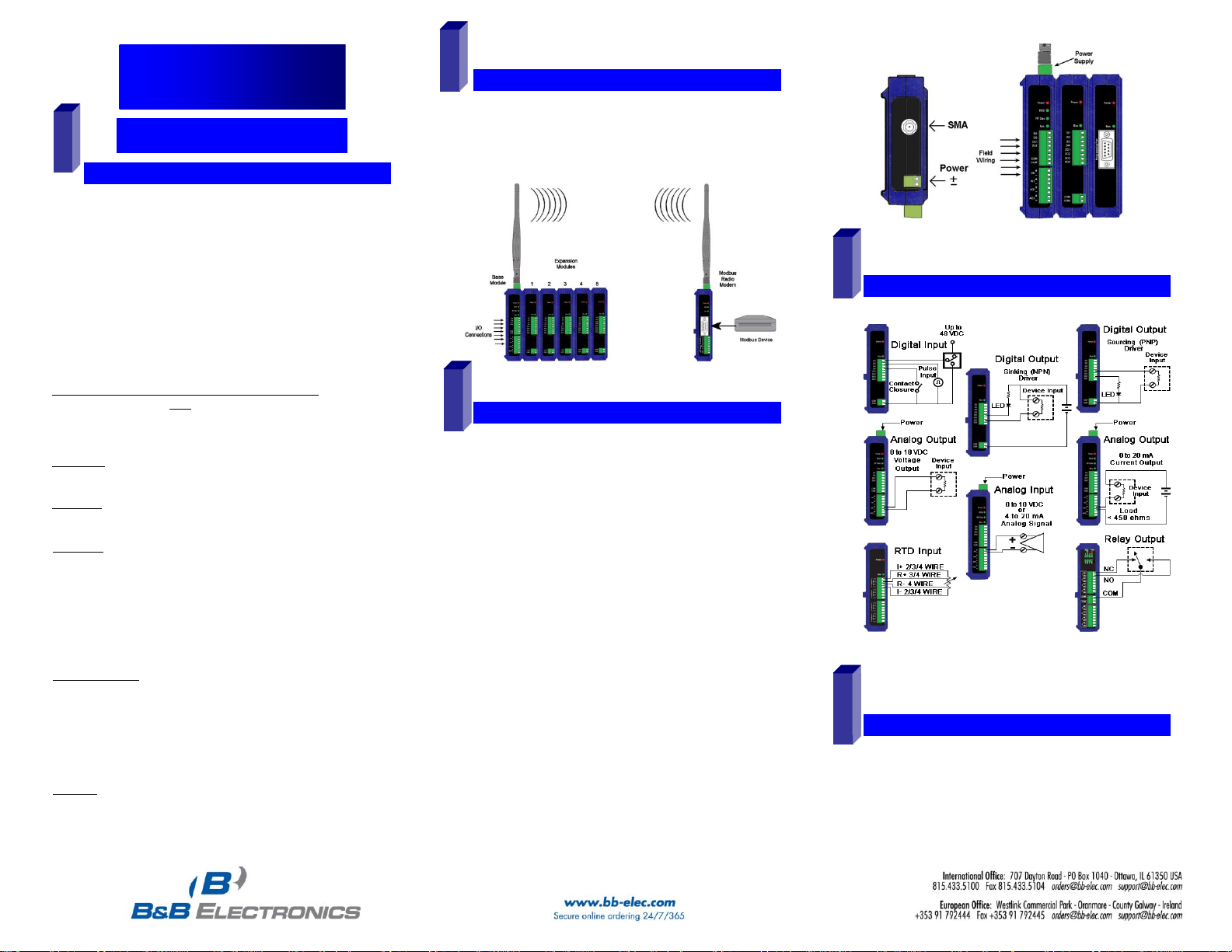
Select a radio modem to match the type of Zlinx I/O Base
Module (SR, MR or LR).
Select a Base Module and Expansion Modules based on
the type of I/O needed.
Perform an installation site survey to ensure adequate
RF coverage and select a mounting location.
Maximum Ambient Air Temperature for all modules is
80°C, with the exception of the ZZ-8DO-R, which is 65°C
Mount and connect together the Base and Expansion
Modules (Expansion Modules on the right side of the
Base).
Plug the Configuration Box into the right side of the Zlinx
I/O system.
Attach antennas to the Base Module and to the Modbus
radio modem.
Mount and connect together Modbus radio modem and
Modbus device.
Ensure that the Modules are attached appropriately.
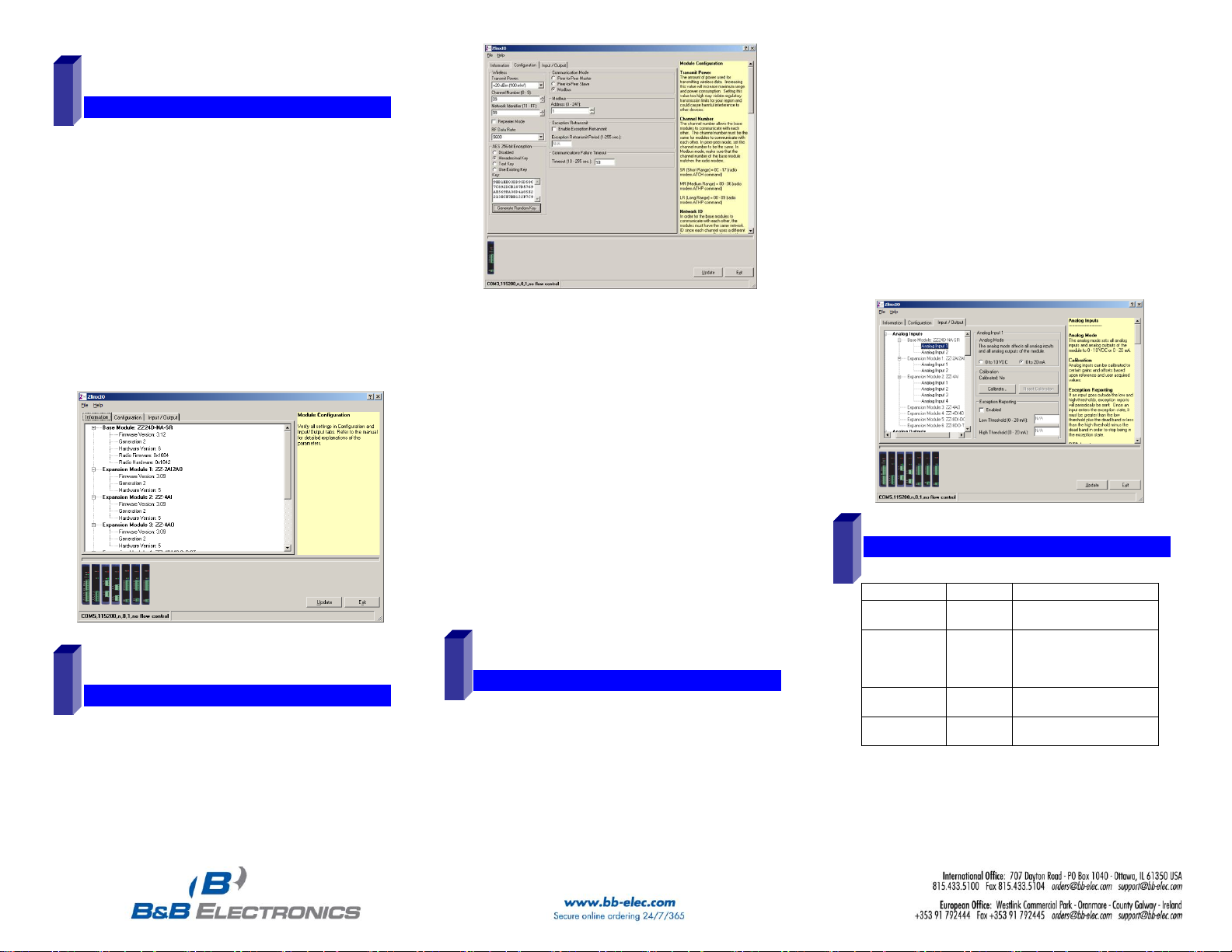
Connect field wiring to Zlinx I/O terminals.
Connect power to the Base Module:
Connect power to the Modbus radio modem:
Refer to the Installation Manual for power and wattage
requirements.
7516R8_ZlinxIO-0812qsg – Modbus Mode
Refer to the User Manual for Input / Output Voltage and
Current Ratings
Insert the I/O Manager software CD. Installation should
launch automatically. If not, click Start, Run,
[drive]:\ZlinxMgr.exe, where [drive] is your CD-Rom drive.
Follow the prompts to install the Zlinx I/O Manager.
Page 2
SSttaarrtt ZZlliinnxx II//OO MMaannaaggeer
r
CCoonnffiigguurree CCoommmmuunniiccaattiioonn MMooddee
CCoonnffiigguurree IInnppuutt//OOuuttppuutt
OOppeerraattiioonn
LED
STATUS
FUNCTION
Power
Red
Solid
Power applied
RSSI
Tricolor
Off
Red
Yellow
Green
No radio signal
Weak radio signal
OK radio signal
Strong radio signal
RF Data
Green
Off
Blinking
No radio link data
Radio link data TD/RD traffic
Bus
Green
Off
Blinking
No local bus data
Local bus data TD/RD traffic
6
7
8
9
Connect a PC serial port (COM1 to 16) to the
Configuration Box using a straight-through serial cable or
USB cable if using a ZZ-PROG1-USB Module.
Click Start\Programs\B&B Electronics\Zlinx\Zlinx
Manager\Zlinx Manager, then click Zlinx I/O and then
Zlinx I/O Configuration. It will auto-search for attached
Zlinx Modules on startup. Zlinx I/O will open and display
the Information tab showing model numbers, version
numbers of the attached Base and Expansion Modules.
o Make sure that all Base Modules have the same
firmware revision*
o Make sure that all Expansion Modules have the
same firmware version*
*This can be verified under the Information tab.
On the Configuration tab:
Select the Modbus Mode to communicate with a Modbus
RF modem.
Set the Modbus address to the address number desired
for the Module being configured.
7516R8_ZlinxIO-0812qsg – Modbus Mode
Set Calibration option if you desire to better match a
sensor, or a portion of a signal, to the I/O.
Check Enabled checkbox and set appropriate values for
parameters in Failsafe section to go to the user-defined
values for AO or DO in case of communication failure.
Check Use Output to Indicate Communication Failure
checkbox in Dedicated Comm Fail Alarm section to
configure the first DO on the Base Module to be a
communication failure alarm indicator.
Check Invert Output checkbox to invert the logic of Digital
Outputs on Base or Expansion Modules.
Click Update button to apply the settings.
Configure Wireless settings:
o Select the desired RF Transmit Power (not
applicable for MR models).
o Select the desired OTA data rate (not applicable for
SR, MR, and LR-868 models).
o Set the Channel Number to match the Modbus radio
modem you will be communicating with.
o Set the Network Identifier to match the Modbus radio
modem you will be communicating with.
o If using a MR or ZP9D-115RM-LR-xx radio modem,
set the destination address (ATDT) to 0xFFFF.
o Set Repeater checkbox if the Base is to be a
repeater. Note that ONLY the (MR/ZZ9D-xx-LR-xx)
version supports this.
o Select encryption (not applicable for MR models).
Note: Refer to the manual for more details
concerning wireless settings.
Click Update to save configuration.
Set Analog Inputs and Outputs for 0 to 10 VDC or 0 to 20
mA as required (setting one sets all analog I/O for that
module).
Set Digital Inputs for Discrete or Counter, as required.
Check Enabled checkbox and set appropriate values for
parameters in Exception Reporting section to use the
ability of reporting possible problems on devices.
Refer to Troubleshooting Section of the Manual if operation is
not successful.
Page 3

PPeeeerr--ttoo--PPeeeerr MMooddee
CChheecckk ffoorr AAllll RReeqquuiirreedd HHaarrddwwaarree
SSeelleecctt MMoodduulleess
HHaarrddwwaarree IInnssttaallllaattiioonn
CCoonnnneecctt FFiieelldd WWiirriinng
g
IInnssttaallll ZZlliinnxx II//OO SSooffttwwaarre
e
SSttaarrtt ZZlliinnxx II//OO MMaannaaggeer
r
Quick Start Guide
Zlinx™ I/O
1
3
4 2 5
6
System 1
System 2
Zlinx I/O Base Module and Expansion Modules
ZZ-PROG1 Configuration Box or ZZ-PROG1-USB
Module
Straight-through serial cable or USB cable if using
a ZZ-PROG1-USB Module
This Quick Start Guide
Zlinx Wireless Modbus I/O Manual on CD (Can be
downloaded from the Web Site)
Zlinx I/O Manager software on CD (Can be downloaded
from the Web Site)
Special Precautions for UL and UL Class I DIV 2
Note 1: Class 1, Div 2 is not applicable to ZZxD -Nx-MR (medium range),
ZZ8D-Nx-xR (800 MHz) and ZZxD-Nx-xR-AU (Australian) modules.
Note 2: For C1D2 information on ZZ-8DO-R, separate sheet is attached.
WARNING – EXPLOSION HAZARD – SUBSTITUTION OF COMPONENTS
MAY IMPAIR SUITABILITY FOR CLASS I, DIVISION 2.
WARNING – EXPLOSION HAZARD – WHEN IN HAZARDOUS
LOCATIONS, TURN OFF POWER BEFORE REPLACING ANTENNA.
WARNING – EXPLOSION HAZARD – DO NOT DISCONNECT EQUIPMENT
UNLESS POWER HAS BEEN SWITCHED OFF OR THE AREA IS KNOWN
TO BE NONHAZARDOUS.
THIS EQUIPMENT IS SUITABLE FOR USE IN CLASS I, DIVISION 2,
GROUPS A, B, C, AND D, OR UNCLASSIFIED LOCATIONS.
Maximum Ambient Air Temperature 80°C (176°F) except for ZZ-8DO-R.
Wiring Terminals:
Copper Wire Only
One Conductor per Terminal
Wire Range 28 to 16 AWG
Tightening Torque 1.7 lb-in
Temperature Rating of Field Wiring – 105° C (221° F) minimum sized for
60° C (140°F) ampacity.
Warning – 2 DIN rail end brackets (supplied with each expansion
module) must be installed, one on each end of the assembled system on
the DIN rail to mechanically secure the individual products.
Select the Base and Expansion Modules required for the
location and coverage distances
Ensure that two systems are complementary, i.e. the inputs
of the Modules in System 1 (see figure below) match the
outputs of the corresponding Modules in System 2.
Perform an installation site survey to ensure adequate
RF coverage and select a mounting location.
Maximum Ambient Air Temperature for all modules is
80°C, with the exception of the ZZ-8DO-R, which is 65°C
Mount and connect together two systems of the Base
and Expansion Modules (Expansion Modules on the right
side of the Base).
Ensure that the Modules are attached properly.
Plug the Configuration Box into the right side of the
system.
7516R8_ZlinxIO-0812qsg – Peer-to-Peer Mode
Attach the antennas to the Base Modules.
Connect field wiring to Zlinx I/O terminals.
Refer to the Installation Manual for power and wattage
requirements
Refer to the User Manual for Input / Output Voltage and
Current Ratings
Insert the I/O Manager software CD. Installation should
launch automatically. If not, click Start, Run,
[drive]:\ZlinxMgr.exe, where [drive] is your CD-Rom drive.
Follow the prompts to install the Zlinx I/O Manager.
Connect a PC serial port (COM1 to 16) to the
Configuration Box using a straight-through serial cable or
USB cable if using a ZZ-PROG1-USB module
Click Start\Programs\B&B Electronics\Zlinx\Zlinx
Manager\Zlinx Manager, then click Zlinx I/O and then
Zlinx I/O Configuration. It will auto-search for attached
Page 4

Zlinx Modules on startup. Zlinx I/O will open and display
CCoonnffiigguurree CCoommmmuunniiccaattiioonn MMooddee
CCoonnffiigguurree IInnppuutt//OOuuttppuutt
OOppeerraattiioonn
LED
STATUS
FUNCTION
Power
Red
Solid
Power applied
RSSI
Tricolor
Off
Red
Yellow
Green
No radio signal
Weak radio signal
OK radio signal
Strong radio signal
RF Data
Green
Off
Blinking
No radio link data
Radio link data TD/RD traffic
Bus
Green
Off
Blinking
No local bus data
Local bus data TD/RD traffic
7
8
9
the Information tab showing model numbers, version
numbers of the attached Base and Expansion Modules.
o Make sure that all Base Modules have the same
firmware revision*
o Make sure that all Expansion Modules have the
same firmware version*
*This can be verified under the Information tab.
On the Configuration tab:
Select Peer-to-Peer (P2P) Master on one set of Zlinx I/O
Modules and P2P Slave on the other set of Zlinx I/O
Modules.
Configure System 1 (see figure in Section 2) as described
below:
o Set the P2PMaster address to match the Slave.
o Set Polling Rate to update at an acceptable rate.
o Set Retry Count for number of tries before lost
communication indication is required.
o Configure the Wireless settings:
Select the desired RF Transmit Power (not
applicable for MR models).
Select the desired OTA Data Rate (not applicable
for SR, MR, and LR-868 models).
Set Channel Number to match the device you will
be communicating with.
Set Network Identifier to match device you will be
communicating with.
Select Encryption (not applicable to MR models).
Note: Refer to the manual for more details
concerning wireless settings.
o Click Update to save configuration.
Configure System 2 (see figure in Section 2) as
described below:
o Set the P2P Slave address to match the Master.
o Set Polling Rate to update at an acceptable rate.
o Set Retry Count for number of tries before lost
communication indication is required.
o Configure the Wireless settings:
Select the desired RF Transmit Power (not
applicable for MR models).
Select the desired OTA Data Rate (not applicable
for SR, MR, and LR-868 models)
Set Channel Number to match device you will be
communicating with.
Set Network Identifier to match device you will be
communicating with.
Select Encryption (not applicable to MR models)
Note: Refer to the manual for more details
concerning wireless settings.
o Click Update to save configuration.
Set Analog Inputs and Outputs for 0 to 10 VDC or 0 to 20
mA as required (setting one sets all analog I/O for that
Module).
Set Digital Inputs for Discrete or Counter, as required.
Set Calibration option if you desire to better match a
sensor, or a portion of a signal, to the I/O.
7516R8_ZlinxIO-0812qsg – Peer-to-Peer Mode
Check Enabled checkbox and set appropriate values for
parameters in Failsafe section to go to the user-defined
values for AO or DO in case of communication failure.
Check Use Output to Indicate Communication Failure
checkbox in Dedicated Comm Fail Alarm section to
configure the first DO on the Base Module to be a
communication failure alarm indicator.
Check Invert Output checkbox to invert the logic of Digital
Outputs on Base or Expansion Modules.
Click Update button to apply the settings.
Refer to the Troubleshooting Section of the Manual if operation
is not successful.
 Loading...