

Page 1
Quick Start Guide
Zlinx™ Xtreme I/O
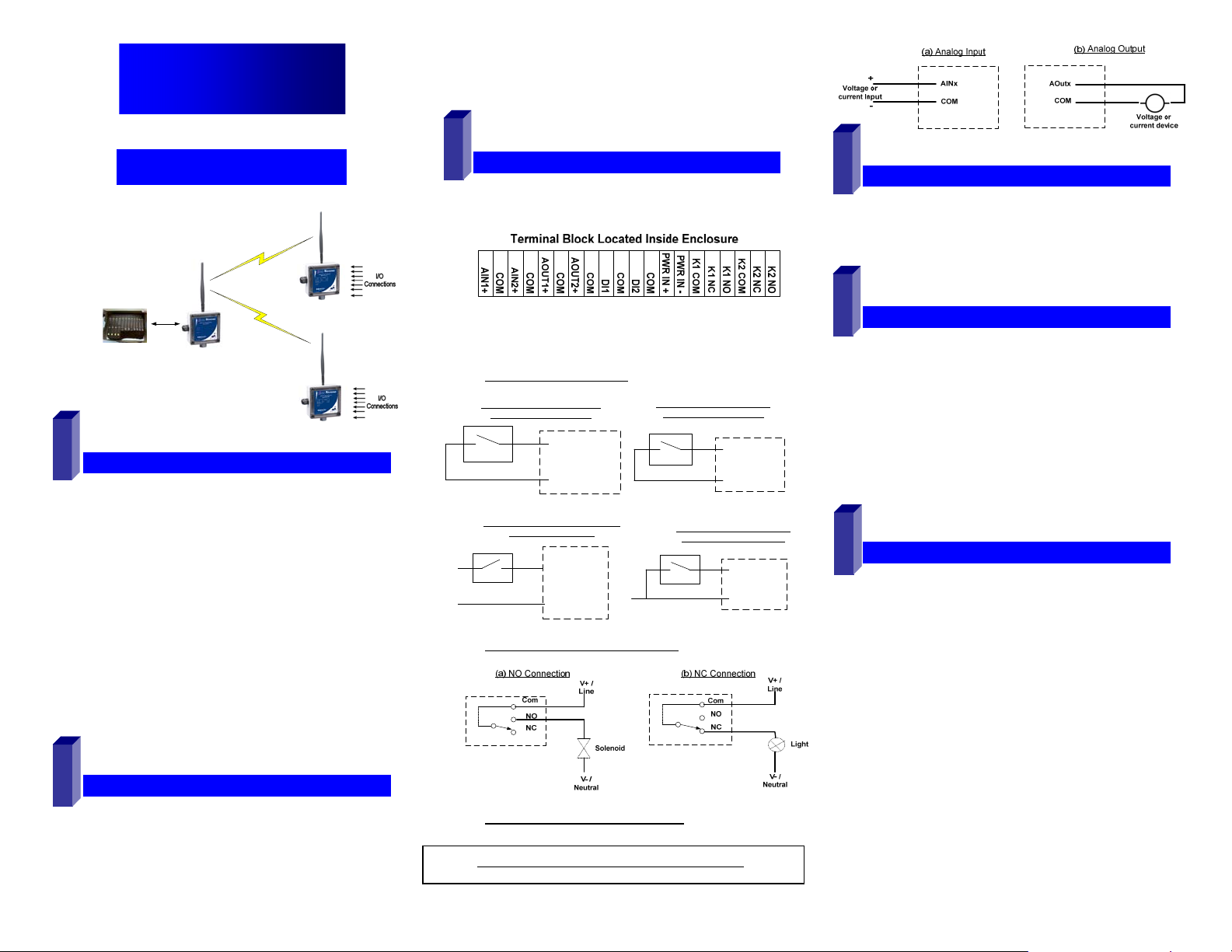
MMooddbbuuss MMooddee
I/O Module
Radio Modem
Process
Controller
Modbus RTU Master
1
CChheecckk RReeqquuiirreedd HHaarrddwwaarree
Zlinx Xtreme I/O Modules & Radio Modem of same type
o ZXT24-IO-222R2 and ZXT24-RM (OR)
o ZXT9-IO-222R2 and ZXT9-RM
This Quick Start Guide
CD with Zlinx™ Manager Software and manual
Antenna
Mounting ears and hardware
Additional items required but not included:
o 10 – 30 VDC Power Supply
o USB Cable
Conduit mounting accessories sold separately model:
ZXTMT
o Cable Gland
o Conduit Accessories
2
IInnssttaallll HHaarrddwwaarree
Mount the Zlinx Xtreme I/O module & the Radio Modem
Serial
Connection
I/O Module
pn 8590R1-ZXTx-IO-x-2011QSG –Peer-to-Peer Mode
Attach antennas to the RPSMA connectors
Attach Conduit hubs, cable glands, etc. as necessary.
Plug the unused hole, if any, using the Membrane Gland.
Accessories kit ZXTMT sold separately.
3
CCoonnnneecctt FFiieelldd WWiirriinngg
See Section 11 – “UL Class 1 Div 2 Requirements” for
wiring instructions.
Power Supply Connections:
Connect the10-30 VDC power supply to the PWR IN
+/- terminals on the terminal blocks.
Digital Input Connections:
(a) PNP (Sourcing) Input Wiring
with Internal Power Supply
PWR IN +
DIx
(c) PNP (Sourcing) Input Wiring with
External Power Supply
+V
Com
Digital Output (Relay) Connections:
Analog Input & Output Connections:
DIx
Com
(b) NPN (Sinking) Input Wiring
with Internal Power Supply
(d) NPN (Sinking) Input Wiring
with External Power Supply
Com
DIx
Com
DIx
Com
4
IInnssttaallll ZZlliinnx
Insert the CD into your CD ROM Drive. The Zlinx™
Manager Install Wizard should start. Follow the on-screen
instructions to install the software.
If auto run is disabled, locate the ZlinxMgr.exe file on the
CD-ROM drive and double click to launch it. The Install
Wizard should start. Follow the on-screen instructions.
5
IInnssttaallll UUSSBB DDrriivveerrss
Connect the I/O module to the USB port on your PC.
The “Found New Hardware Wizard” will guide you through
the installation process.
When prompted to connect to Windows Updates to search for
drivers, select “No, not at this time” and follow the instructions
for installing from the CD or the location on the hard drive.
Choose the drivers manually from the CD or the location
where Zlinx™ Manager Software is installed.
When the driver is installed a new COM port labeled
“Xtreme” will show up in Windows Device Manager.
6
EEaassyy MMooddee CCoonnffiigguurraattiioonn
With power applied to the Zlinx Xtreme I/O module, press
and HOLD the Configuration Push Button on the inside
top lid until all the Mode LED’s on the front cover flash.
A single LED will flash depending on the current mode
Press the Push Button until the configuration mode
increments to Modbus mode. Modbus LED will be ON.
If the Push Button is not pressed for 4 sec, the device will
exit with Modbus mode selected.
The Zlinx Xtreme I/O module is now ready to communicate to
the Radio Modem in default mode.
Detailed setup changes can be done using the Zlinx
Manager Software using the following steps.
M
TTM
x
MMaannaaggeerr SSooffttwwaarree
Refer to Zlinx Xtreme I/O manual for more details
Page 2
7
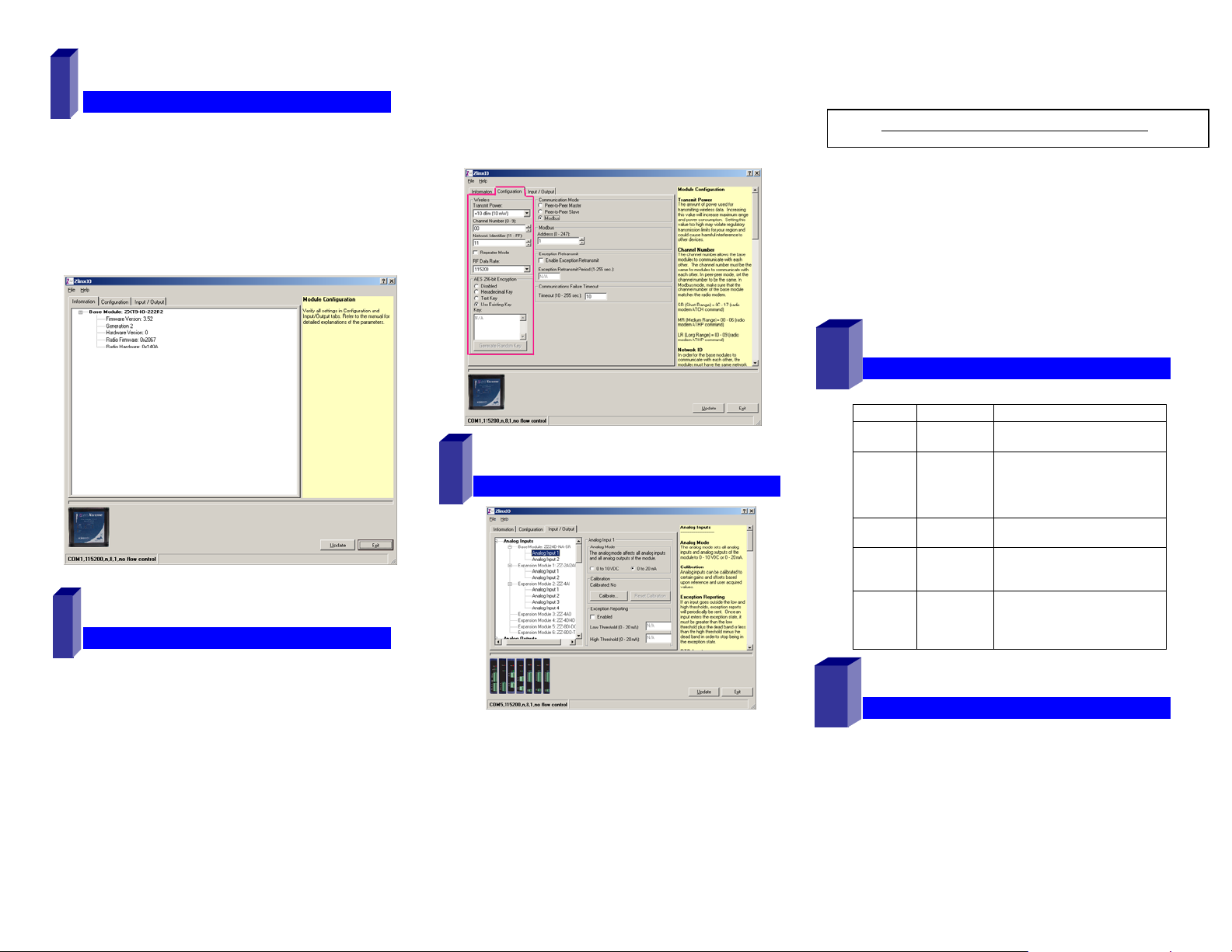
SSttaarrtt ZZlliinnxx II//OO MMaannaaggeer
Connect the USB port of your PC to the Zlinx Xtreme I/O
module using a USB cable.
Click Start\Programs\B&B Electronics\Zlinx\Zlinx
Manager\Zlinx Manager, then click Zlinx I/O and then
Zlinx I/O Configuration. It will auto-search for attached
Zlinx Xtreme I/O Module on startup. Zlinx I/O will open
and display the Information tab showing the I/O model
number, version numbers and firmware rev levels.
r
Set encryption key to match that of the Modbus radio
modem.
Select the communication mode to ‘Modbus’ Mode.
Set the Modbus address to the address number desired
for the Module being configured.
Click Update to save configuration.
pn 8590R1-ZXTx-IO-x-2011QSG –Peer-to-Peer Mode
Configure each Analog Inputs and Outputs in one of the
following modes
o 0-5V, 0-10V, 0-20mA, 4-20mA
Refer to Zlinx Xtreme I/O manual for more details
Set Exception Reporting for Analog Inputs and Fail Safe
settings for Analog Outputs if necessary.
Set Calibration option if you desire to better match a
sensor, or a portion of a signal, to the I/O.
Refer to appropriate sections in the Zlinx Xtreme I/O
manual.
Click Update button to apply the settings.
8
CCoonnffiigguurree CCoommmmuunniiccaattiioonn MMooddee
On the Configuration tab:
Configure Wireless settings:
o Select the desired RF Transmit Power
o Set the Channel Number to match the Modbus Radio
Modem you will be communicating with.
o Set the Network Identifier to match the Modbus
Radio Modem you will be communicating with.
o Set Repeater checkbox if desired. Note that ONLY
the (ZXT9-IO- xx) modules supports this mode.
10
9
CCoonnffiigguurree IInnppuuttss//OOuuttppuuttss
OOppeerraattiioonn
LED
Power
RSSI
(8 LED
bar
graph)
Wireless Off
Mode
I/O
Status
STATUS FUNCTION
Solid
Flash
0
1-3
4-6
7-8
Blinking
Modbus
P2P Master
P2P Slave
DI1
DI2
DO1
DO2
Power applied
Communication Fail
No signal
Weak signal
OK signal
Strong signal
No radio link data
Wireless data Transmit / Receive
Modbus Mode
Peer-to-Peer Master
Peer-to-Peer Slave
Digital Input 1 ON
Digital Input 2 ON
Digital Output (Relay) 1 ON
Digital Output (Relay) 2 ON
Set Digital Inputs for Discrete or Counter, as required.
o Choose PNP or NPN selection as appropriate.
Each input is individually configurable.
Configure Digital Relay Outputs. Enable the Fail Safe
and Communications Fail Alarm if necessary.
11
UULL CCllaassss 11 DDiivv 22 RReeqquuiirreemmeennttss
Operating Voltage – 10 to 30 VDC
WARNING: SUITABLE FOR USE IN CLASS I, DIVISION 2,
GROUPS A, B, C AND D HAZARDOUS LOCATIONS, OR
NONHAZARDOUS LOCATIONS ONLY.
Page 3

WARNING - EXPLOSION HAZARD - SUBSTITUTION OF ANY
COMPONENT MAY IMPAIR SUITABILITY FOR CLASS I,
DIVISION 2.
WARNING – EXPLOSION HAZARD – WHEN IN HAZARDOUS
LOCATIONS, TURN OFF POWER BEFORE REPLACING
ANTENNA.
Intended use of equipment – please see the B&B Electronics
Data Sheets and Quick Start Guides for each Zlinx Xtreme
product for explanations of the intended use of this equipment.
Wiring Terminals – Use Copper Wire Only, one conductor per
terminal
Wire Range 30 – 12 AWG
Maximum Surrounding Ambient Air Temperature - 74°C
UL Class I, Division 2 wiring methods. The Zlinx Xtreme
enclosure is provided with two conduit knockouts that serve as
wiring provisions for Class I, Division 2 wiring methods per the
National Electrical Code (NEC).
The following instructions include procedures to be followed in
order to ensure UL "separation between circuits" as defined in
the NEC.
The low-voltage (LV) wiring – DC power, analog & digital signals
– must be separated from the high voltage (HV) wiring for the
relay contacts. In all cases HV wiring must be rated minimum
250V.
Separation between circuits can be accomplished by using one
of the three following methods:
a. Use one conduit knockout to route LV wiring and the
second conduit knockout to route the HV wiring, OR
see methods 2 and 3 below.
The remaining two methods use one conduit
knockout for all wiring. In this case a UL Recognized
(UL type QCRV2) conduit plug must be used per the
NEC to plug the second conduit knockout.
b. Enclose LV wiring in a 250V rated insulated sheath
to separate it from the HV wiring, OR
c. Use 250vac rated wires for both LV and HV wiring.
Temperature rating of field installed conductors - Field
conductors shall be rated 60C/75C minimum (either are
acceptable) and sized accordingly.
When conduit openings are not being used, a UL Recognized
plug (type QCRV2) shall be used.
The following is UL-required information regarding the Sealed
Relay Devices:
WARNING – Exposure to some chemicals may degrade the
sealing properties of materials used in the Sealed Relay Device.
RECOMMENDATION – It is recommended to inspect the
sealed relay device periodically and to check for any
degradation of the materials and to replace the component
product, not the sealed device, if any degradation is found.
Sealed Relay Device Information:
Sealed Device: Relay Models G6RL-14-ASI-DC5, G6RL14-ASI-DC6, G6RL-14-SR-ASI-DC5 or G6RL-14-SR-ASIDC6 manufactured by Omron Corp.
Manufacturer Type
Relay Case and
Base
Mitsubishi
Engineering
5010GN6-30M8AM
Plastics
Corp.
Sealant
Three Bond
TB2225G
Ltd.
pn 8590R1-ZXTx-IO-x-2011QSG –Peer-to-Peer Mode
Page 4

Quick Start Guide
Zlinx™ Xtreme I/O
PPeeeerr--ttoo--PPeeeerr MMooddee
1
CChheecckk ffoorr AAllll RReeqquuiirreedd HHaarrddwwaarree
Two Zlinx Xtreme I/O Modules of same type
o ZXT24-IO-222R2 (OR)
o ZXT9-IO-222R2
This Quick Start Guide
CD with Zlinx™ Manager Software and manual
Antenna
Mounting ears and hardware
Additional items required but not included:
o 10 – 30 VDC Power Supply
o USB Cable
Conduit mounting accessories sold separately, model
ZXTMT
o Cable Gland
o Conduit Accessories
2
IInnssttaallll HHaarrddwwaarree
Mount the Zlinx Xtreme I/O modules
pn 8590R1-ZXTx-IO-x-2011QSG –Peer-to-Peer Mode
Attach antennas to the RPSMA connectors
Attach Conduit hubs, cable glands, etc. as necessary.
Plug the unused hole, if any, using the Membrane Gland.
Accessories kit ZXTMT sold separately.
Analog Input & Output Connections:
3
CCoonnnneecctt FFiieelldd WWiirriinngg
See Section 11 – “UL Class 1 Div 2 Requirements” for
wiring instructions.
Power Supply Connections:
Connect the10-30 VDC power supply to the PWR IN
+/- terminals on the terminal blocks.
Digital Input Connections:
(a) PNP (Sourcing) Input Wiring
with Internal Power Supply
PWR IN +
DIx
(c) PNP (Sourcing) Input Wiring with
External Power Supply
+V
Com
Digital Output (Relay) Connections:
Refer to Zlinx Xtreme I/O manual for more details
DIx
Com
(b) NPN (Sinking) Input Wiring
with Internal Power Supply
(d) NPN (Sinking) Input Wiring
with External Power Supply
Com
DIx
Com
DIx
Com
M
TTM
IInnssttaallll ZZlliinnx
4
Insert the CD into your CD ROM Drive. The Zlinx™
Manager Install Wizard should start. Follow the on-screen
instructions to install the software.
If auto run is disabled, locate the ZlinxMgr.exe file on the
CD-ROM drive and double click to launch it. The Install
Wizard should start. Follow the on-screen instructions.
5
IInnssttaallll UUSSBB DDrriivveerrss
Connect the I/O module to the USB port on your PC.
The “Found New Hardware Wizard” will guide you through
the installation process.
When prompted to connect to Windows Updates to search for
drivers, select “No, not at this time” and follow the instructions
for installing from the CD or the location on the hard drive.
Choose the drivers manually from the CD or the location
where Zlinx™ Manager Software is installed.
When the driver is installed a new COM port labeled
“Xtreme” will show up in Windows Device Manager.
6
EEaassyy MMooddee CCoonnffiigguurraattiioonn
With power applied to the Zlinx Xtreme I/O module, press
and HOLD the Configuration Push Button on the inside
top lid until all the Mode LED's on the front cover flash.
A single LED will flash depending on the current mode
In one I/O module, press the Push Button until the
configuration mode increments to P2P Master mode.
Corresponding LED will be flashing.
If the Push Button is not pressed for 4 sec, the device will
exit with ‘P2P Master’ mode selected.
Using similar steps to above, set the other I/O module to
‘P2P Slave’ mode
x
MMaannaaggeerr SSooffttwwaarree
Page 5

Now the Zlinx Xtreme I/O modules are ready to
communicate Peer-to-Peer mode with default setup.
Detailed setup can be done using the Zlinx Manager
using the following steps.
7
r
SSttaarrtt ZZlliinnxx II//OO MMaannaaggeer
Connect the USB port of your PC to the Zlinx Xtreme I/O
module using a USB cable.
Click Start\Programs\B&B Electronics\Zlinx\Zlinx
Manager\Zlinx Manager, then click Zlinx I/O and then
Zlinx I/O Configuration. It will auto-search for attached
Zlinx Xtreme I/O Module on startup. Zlinx I/O will open
and display the Information tab showing the I/O model
number, version numbers and firmware rev levels.
Select the communication mode to ‘P2P Master’ Mode.
Set the P2P Master address as desired.
Set Polling Rate and Retry Count.
Click Update to save configuration.
P2P Slave Configuration – From Configuration tab
Configure Wireless settings:
o Select the desired RF Transmit Power
o Set the Channel Number to match that of master.
o Set the Network Identifier to match that of master.
o Set encryption key the same as that of master.
Select the communication mode to ‘P2P Slave’ Mode.
Set the P2P Salve address to match that of Master.
Click Update to save configuration
pn 8590R1-ZXTx-IO-x-2011QSG –Peer-to-Peer Mode
Configure each Analog Inputs and Outputs in one of the
following modes
o 0-5V, 0-10V, 0-20mA, 4-20mA
Set Exception Reporting for Analog Inputs and Fail Safe
settings for Analog Outputs if necessary.
Set Calibration option if you desire to better match a
sensor, or a portion of a signal, to the I/O.
Refer to appropriate sections in the Zlinx XtremeI/O
manual.
Click Update button to apply the settings.
8
CCoonnffiigguurree CCoommmmuunniiccaattiioonn MMooddeess
P2P Master Configuration – From Configuration tab
Configure Wireless settings:
o Select the desired RF Transmit Power
o Set the Channel Number.
o Set the Network Identifier.
o Set Repeater checkbox if desired. Note that ONLY
the (ZXT9-IO- xx) modules supports this mode.
o Set encryption key.
10
OOppeerraattiioonn
9
CCoonnffiigguurree IInnppuutt//OOuuttppuutt
Set Digital Inputs for Discrete. Counter configuration is
not applicable to Peer-to-Peer mode
o Choose PNP or NPN selection as appropriate.
Each input is individually configurable.
Configure Digital Relay Outputs.
Enable the Fail Safe and Communications Fail Alarm if
necessary.
Refer to Zlinx Xtreme I/O manual for more details
LED
Power
RSSI
(8 LED
bar
graph)
Wireless Off
Mode
I/O
Status
STATUS
Solid
Flash
0
1-3
4-6
7-8
Blinking
Modbus
P2P Master
P2P Slave
DI1
DI2
DO1
DO2
FUNCTION
Power applied
Communication Fail
No signal
Weak signal
OK signal
Strong signal
No radio link data
Wireless data Transmit / Receive
Modbus Mode
Peer-to-Peer Master
Peer-to-Peer Slave
Digital Input 1 ON
Digital Input 2 ON
Digital Output (Relay) 1 ON
Digital Output (Relay) 2 ON
Page 6

11
UULL CCllaassss 11 DDiivv 22 RReeqquuiirreemmeennttss
Operating Voltage – 10 to 30 VDC
WARNING: SUITABLE FOR USE IN CLASS I, DIVISION
2, GROUPS A, B, C AND D HAZARDOUS LOCATIONS,
OR NONHAZARDOUS LOCATIONS ONLY.
WARNING - EXPLOSION HAZARD - SUBSTITUTION
OF ANY COMPONENT MAY IMPAIR SUITABILITY FOR
CLASS I, DIVISION 2.
WARNING – EXPLOSION HAZARD – WHEN IN
HAZARDOUS LOCATIONS, TURN OFF POWER BEFORE
REPLACING ANTENNA.
Intended use of equipment – please see the B&B
Electronics Data Sheets and Quick Start Guides for each
Zlinx Xtreme product for explanations of the intended use of
this equipment.
Wiring Terminals – Use Copper Wire Only, one conductor
per terminal
Wire Range 30 – 12 AWG
Maximum Surrounding Ambient Air Temperature - 74°C
UL Class I, Division 2 wiring methods. The Zlinx Xtreme
enclosure is provided with two conduit knockouts that serve
as wiring provisions for Class I, Division 2 wiring methods
per the National Electrical Code (NEC).
The following instructions include procedures to be followed
in order to ensure UL "separation between circuits" as
defined in the NEC.
The low-voltage (LV) wiring – DC power, analog & digital
signals – must be separated from the high voltage (HV)
wiring for the relay contacts. In all cases HV wiring must be
rated minimum 250V.
pn 8590R1-ZXTx-IO-x-2011QSG –Peer-to-Peer Mode
Separation between circuits can be accomplished by using one
of the three following methods:
a. Use one conduit knockout to route LV wiring and the
second conduit knockout to route the HV wiring, OR
see methods 2 and 3 below.
The remaining two methods use one conduit
knockout for all wiring. In this case a UL Recognized
(UL type QCRV2) conduit plug must be used per the
NEC to plug the second conduit knockout.
b. Enclose LV wiring in a 250V rated insulated sheath
to separate it from the HV wiring, OR
c. Use 250vac rated wires for both LV and HV wiring.
Temperature rating of field installed conductors - Field
conductors shall be rated 60C/75C minimum (either are
acceptable) and sized accordingly.
When conduit openings are not being used, a UL
Recognized plug (type QCRV2) shall be used.
The following is UL-required information regarding the
Sealed Relay Devices:
WARNING – Exposure to some chemicals may degrade
the sealing properties of materials used in the Sealed
Relay Device.
RECOMMENDATION – It is recommended to inspect the
sealed relay device periodically and to check for any
degradation of the materials and to replace the
component product, not the sealed device, if any
degradation is found.
Sealed Relay Device Information:
Sealed Device: Relay Models G6RL-14-ASI-DC5, G6RL14-ASI-DC6, G6RL-14-SR-ASI-DC5 or G6RL-14-SR-ASIDC6 manufactured by Omron Corp.
Relay Case and
Base
Sealant
Manufacturer Type
Mitsubishi
Engineering
Plastics
Corp.
Three Bond
Ltd.
5010GN6-30M8AM
TB2225G
 Loading...