

Page 1
Documentation Number –p/n 8577R1 ZP9D-115RM-LR-0812qsg
CChheecckk ffoorr AAllll RReeqquuiirreedd HHaarrddwwaarree
ZLINX™ ZP9D-115RM-LR
This Quick Start Guide
CD with ZLINX™ Manager Software and manual
Antenna
Terminal Block (Attached)
Additional items required but not included:
o 10 – 48 VDC / 18 – 30 VAC) 6.0 W Power Supply
o Serial Cable
Special Precautions for UL and UL Class I DIV 2
WARNING – EXPLOSION HAZARD – SUBSTITUTION OF
COMPONENTS MAY INPAIR SUITABILITY FOR CLASS I,
DIVISION 2
WARNING – EXPLOSION HAZARD – WHEN IN HAZARDOUS
LOCATIONS, TURN OFF POWER BEFORE REPLACING
ANTENNA
WARNING – EXPLOSION HAZARD – DO NOT DISCONNECT
EQUIPMENT UNLESS POWER HAS BEEN SWITCHED OFF
OR THE AREA IS KNOWN TO BE NONHAZARDOUS
THIS EQUIPMENT IS SUITABLE FOR USE IN CLASS I,
DIVISION 2, GROUPS A, B, C, AND D OR UNCLASSIFIED
LOCATIONS
Maximum Ambient Air Temperature 85°C (185°F)
Wiring Terminals:
Copper Wire Only
One Conductor per Terminal
Wire Range 28 to 16 AWG
Tightening Torque 1.7 lb-in
Temperature Rating of Field Wiring – 105° C (221° F) sized
for 60° C (140°F) ampacity.
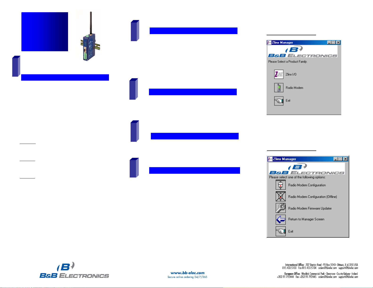
Radio Modem Options Screen
Quick Start
Guide
ZP9D-115RM-LR
Zlinx™ Radio
Modem
IInnssttaallll ZZlliinnx
x
™
™
MMaannaaggeerr SSooffttwwaarree
Insert the CD into your CD ROM Drive. The Zlinx™
Manager Install Wizard should start. Follow the onscreen instructions to install the software.
If auto run is disabled, locate the Zlinx Manager file on
the CD and double click it. The Install Wizard should
start. Follow the on-screen instructions.
2
1
SSttaarrtt tthhee ZZlliinnx
x
™
™
MMaannaaggeerr SSooffttwwaarree
Start the Zlinx™ Manager Software.
Click the Radio Modem Button.
Click the Radio Modem Configuration Button.
o Select your COM port and configure it for 9600 baud,
Data Bits: 8, Parity: None, Stop Bit: 1.
Click the Connect Button.
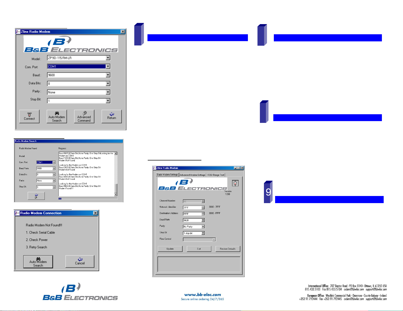
When the software locates the Radio Modem, the Basic
Modem Settings Screen will be displayed. This screen
will display the Model Number, Function Set Type,
Firmware Version, Network Identifier, Destination
Address, Baud Rate, and Parity.
If the settings where changed from the default, Auto
Modem Search can be used to locate the modem. The
Auto Search will use a sequence of COM Ports and
settings until a response is received. If there is still no
response, double check the power supply and serial
cable. Also, make sure that no other devices are
attached and that the unit is not set to RS-422/485 2wire.
5
CCoonnnneecctt PPoowweerr SSuuppppllyy
A 10 to 48 VDC or 18 to 30 VAC external power supply
is required.
Connect the power supply to the power terminal block
located on the top of the radio modem.
3
4
CCoonnnneecctt SSeerriiaall CCaabbllee && AAnntteennnnaa
Connect a straight through RS-232 cable between the
Radio Modem and your PC.
Connect the antenna to the Radio Modem.
Zlinx™ Manager Start Screen
Page 2
Documentation Number –p/n 8577R1 ZP9D-115RM-LR-0812qsg
Click the Update Button to store the settings.
Click the Advanced Modem Settings TAB. Check the Power
Level (PL). Select the appropriate power level for your
application. For bench testing, PL should be set to 0 and
Radio Modems should be separated by at least 1 meter.
When using higher power levels, separate the modems by
at least 7 meters.
If you changed any settings, store them by clicking the
Update button.
SSeett uupp yyoouurr sseeccoonndd RRaaddiioo MMooddeemm
Exit Configuration. Power off the Radio Modem (wait at least
30 seconds before re-applying power to this Radio Modem.
Configure your second Radio Modem using the same
procedure. Do not proceed to the RSSI Range Test step until
you have a second modem configured. Two properly
configured units are required to proceed to the next step.
Configure the second unit with the same settings.
CCoonnffiigguurree ttoo MMaattcchh YYoouurr SSeerriiaall DDeevviicceess
Configure the Radio Modems to match the serial devices
you will be connecting to.
The DB9 is wired as a DCE device. If you are connecting to
another DCE device, a cross-over cable will be required.
For the RS-422/485 terminals, TD is output, RD is input.
Ensure you match the signal polarity.
o 2-Wire Mode: TDA(-) TDB(+), SW1 & 2
ON.
o Wiring Examples are located in the
manual.
You are now ready to install your Radio Modems in the field.
RRSSSSII RRaannggee TTeesstt
Set one the remote modem to Loopback Mode. Loopback
connections can be made using the RS-422/485 interface
by setting switch 1 and 2 to ON and 3 and 4 to OFF
(internal loopback with echo on). You can also use the DB9
connections by bridging pins 2 and 3.
On the Radio Modem that is NOT set up for Loopback Mode,
run the RSSI Range Test. Observe the following
indications:
o The DATA and RSSI will flash as data is
sent between the two units.
o Test results will be displayed on the RSSI
Range Test Screen.
6
8
On-line Configuration Screen
Radio Modem Found Screen
Radio Modem Not Found Screen
SSeettuupp tthhee RRaaddiioo MMooddeemm
Select a unique Network Identifier. This is especially
important if you have other units operating in the same
area.
Set the Destination Address to FFFF (broadcast).
If desired, you can change the baud rate and parity on the
Basic Modem Settings Screen. Remember to change your
COM port to match.
Basic Modem Settings Screen
7
 Loading...