

Page 1

Users Guide
Airborne Enterprise Evaluation Kit
WLNN-SE/SP/AN/ER-DP500
Revision 1.4
June 2013
File name: Enterprise WLNN EVB User Guide.doc
Series
Page 2

B&B Electronics
2
Airborne Enterprise WLNN EVB Users Guide
<Page Intentionally Left
Blank>
Page 3

B&B Electronics
Airborne Enterprise WLNN EVB Users Guide
3
Contents
1.0 Overview.................................................................................................................................... 8
2.0 Conventions ............................................................................................................................... 9
2.1 Terminology ........................................................................................................................... 9
2.2 Notes ..................................................................................................................................... 9
2.3 Caution .................................................................................................................................. 9
2.4 File Format ............................................................................................................................. 9
2.5 Courier Typeface ................................................................................................................. 10
3.0 Supported Devices and Kits ..................................................................................................... 11
4.0 Evaluation Board Layout .......................................................................................................... 12
5.1 ANT1 .................................................................................................................................... 14
5.2 ANT2 .................................................................................................................................... 14
5.3 BT1 ....................................................................................................................................... 14
5.4 CN1 ...................................................................................................................................... 15
5.5 CN2 ...................................................................................................................................... 15
5.6 CN3 ...................................................................................................................................... 15
5.7 CN4 ...................................................................................................................................... 16
5.8 CN5 ...................................................................................................................................... 17
5.9 CN6 ...................................................................................................................................... 17
5.10 CN7 / CN13 .......................................................................................................................... 18
5.11 D2 ........................................................................................................................................ 19
5.12 D3 ........................................................................................................................................ 19
5.13 D18 ...................................................................................................................................... 19
5.14 J1 .......................................................................................................................................... 19
5.15 J2 .......................................................................................................................................... 20
5.16 J3 .......................................................................................................................................... 22
5.17 J4 .......................................................................................................................................... 23
5.18 J5 .......................................................................................................................................... 24
5.19 J6 .......................................................................................................................................... 26
5.20 J7 .......................................................................................................................................... 27
5.21 J8 .......................................................................................................................................... 27
5.22 J9 .......................................................................................................................................... 28
5.23 J10 ........................................................................................................................................ 29
5.24 J11 ........................................................................................................................................ 29
5.25 JP1........................................................................................................................................ 30
5.26 LED1 ..................................................................................................................................... 31
5.27 LED2 ..................................................................................................................................... 31
5.28 LED3 ..................................................................................................................................... 31
5.29 LED4 ..................................................................................................................................... 32
5.30 SW1 ..................................................................................................................................... 32
5.31 SW2 ..................................................................................................................................... 32
Page 4

B&B Electronics
4
Airborne Enterprise WLNN EVB Users Guide
5.32 SW3 ..................................................................................................................................... 33
5.33 SW4 ..................................................................................................................................... 33
5.34 TP1 – 6 ................................................................................................................................. 34
5.35 TP7 ....................................................................................................................................... 34
5.36 TP8 - 10 ................................................................................................................................ 36
6.0 A Typical Development System ................................................................................................ 36
7.0 Getting Started ........................................................................................................................ 37
7.1 Unpack the Airborne™ Module EVB Kit ............................................................................... 37
7.2 Attach Antenna and Power-up the EVB .............................................................................. 37
7.3 Install Serial to USB Adapter (Optional) .............................................................................. 37
7.4 Connection to SPI Host ........................................................................................................ 37
8.0 Serial Device Server Connection .............................................................................................. 38
8.1 Connect a Host Computer ................................................................................................... 38
8.2 Interacting with the Airborne™ Module ............................................................................. 38
8.3 Determine and Store the Access Point SSID ........................................................................ 39
8.4 Determine the Module’s IP address .................................................................................... 39
8.5 Accessing the Module Using Telnet .................................................................................... 39
9.0 Ethernet Bridge Connection .................................................................................................... 41
9.1 Connect a Host Computer ................................................................................................... 41
9.2 Interacting with the Airborne™ Module ............................................................................. 41
9.3 Determine and Store the Access Point SSID ........................................................................ 42
9.4 Determine the Module’s IP address .................................................................................... 42
9.5 Accessing the Module Using Telnet .................................................................................... 42
10.0 Using the Web Interface ............................................................................................................ 44
10.1 Navigation Bar ..................................................................................................................... 44
10.2 Navigating the Website ....................................................................................................... 45
10.3 Updating a Field ................................................................................................................... 46
10.4 Uploading Certificates ......................................................................................................... 46
10.5 Upload Configuration Files .................................................................................................. 47
10.6 Updating Firmware .............................................................................................................. 48
11.0 Using the AMC Application ......................................................................................................... 51
12.0 Ethernet Section ......................................................................................................................... 53
13.0 Indicator LED’s ............................................................................................................................ 54
Page 5

B&B Electronics
Airborne Enterprise WLNN EVB Users Guide
5
Tables
Table 1 - Model and kit part numbers ................................................................................................. 11
Table 2 – Summary Description of Evaluation Board .......................................................................... 12
Table 3 - ANT1 Connectors .................................................................................................................. 14
Table 4 - ANT2 Connectors .................................................................................................................. 14
Table 5 - Primary UART CONNECTOR .................................................................................................. 15
Table 6 - Primary UART Connector ...................................................................................................... 15
Table 7 - Ethernet PHY Header Pin Out ............................................................................................... 16
Table 8 - Ethernet Connector Pin Out ................................................................................................. 16
Table 9 - Debug Port Connector .......................................................................................................... 17
Table 10 - Debug Port Pin Out ............................................................................................................. 17
Table 11 - JTAG Header Pin Out .......................................................................................................... 17
Table 12 - SPI Header Pin Out ............................................................................................................. 18
Table 13 - Low Voltage Led indicator .................................................................................................. 19
Table 14 - POWER Status Led indicator ............................................................................................... 19
Table 15 - RF Activity Led Indicator ..................................................................................................... 19
Table 16 - Power Supply Jack .............................................................................................................. 20
Table 17 - Primary Uart Pin Out Header Configuration....................................................................... 20
Table 18 - Primary UART Header Pin-out ............................................................................................ 21
Table 19 - Primary UART Transceiver Configuration ........................................................................... 22
Table 20 - Primary UART Transceiver Header Pin-out ........................................................................ 22
Table 21 - Primary UART LED Indicator Header Pin-out ...................................................................... 23
Table 22 - Secondary UART Pin-out Header Configuration ................................................................. 24
Table 23 - Primary UART Header Pin-out ............................................................................................ 25
Table 24 - Secondary UART Transceiver Configuration ....................................................................... 26
Table 25 - Secondary UART Transceiver Header Pin-out .................................................................... 26
Table 26 - Secondary UART LED Indicator Header Pin-out ................................................................. 27
Table 27 - Ethernet Header Configuration .......................................................................................... 28
Table 28 - Ethernet Header Pin-out .................................................................................................... 28
Table 29 - Airborne Device Server Module Status Indicator Header Pin-out ..................................... 29
Table 30 - GPIO LED Header Configuration ......................................................................................... 29
Table 31 - GPIO LED Header Pin-out ................................................................................................... 29
Table 32 – Ethernet Indicator LED Header Configuration ................................................................... 30
Table 33 – Ethernet Indicator LED Header Pin-out ............................................................................. 30
Table 34 - Power Source Selector........................................................................................................ 30
Table 35 - JP1 Power Selector Pin-out................................................................................................. 30
Table 36 - Primary UART Indicator LED's ............................................................................................. 31
Table 37 - Secondary UART Indicator LED's ........................................................................................ 31
Table 38 – Airborne Device Server Module Indicator LED’s................................................................ 31
Table 39 - LED4 Description ................................................................................................................ 32
Table 40 - TP1-6 Configuration ............................................................................................................ 34
Table 41 - TP7 Label to WLNN Pin-out Table ...................................................................................... 35
Table 42 - UART Authentication .......................................................................................................... 38
Page 6

B&B Electronics
6
Airborne Enterprise WLNN EVB Users Guide
Table 43 - UART SSID & Authentication .............................................................................................. 39
Table 44 - UART Determine Module's IP Address ............................................................................... 39
Table 45 - Ethernet Authentication ..................................................................................................... 41
Table 46 - Ethernet SSID & Authentication ......................................................................................... 42
Table 47 - Ethernet Determine Modules IP Address ........................................................................... 42
Table 48 - Navigation Bar Items .......................................................................................................... 45
Table 49 - Uploading Certificates ........................................................................................................ 47
Table 50 - Uploading Configurations ................................................................................................... 48
Table 51 - Updating Firmware ............................................................................................................. 50
Table 52 - Indicator LED Status Description ....................................................................................... 54
Table 53 - Indicator LED Debug Answers ............................................................................................ 55
Page 7

B&B Electronics
Airborne Enterprise WLNN EVB Users Guide
7
Figures
Figure 1 - Evaluation board layout ...................................................................................................... 12
Figure 2 - Ethernet Jack Pin Out .......................................................................................................... 16
Figure 3 - JTAG Header ........................................................................................................................ 17
Figure 4 - SPI Header ........................................................................................................................... 18
Figure 5 - DE-9 Connector Pin-out ....................................................................................................... 20
Figure 6 - Primary UART Header.......................................................................................................... 21
Figure 7 - Primary UART Transceiver Header ...................................................................................... 22
Figure 8 - Primary UART LED Indicator Header ................................................................................... 23
Figure 9 - DE-9 Connector Pin-out ....................................................................................................... 24
Figure 10 - Secondary UART Header ................................................................................................... 25
Figure 11 - Secondary UART Transceiver Header ................................................................................ 26
Figure 12 - Secondary UART LED Indicator Header ............................................................................. 27
Figure 13 - Airborne Device Server Module Status Indicator Header ................................................. 28
Figure 14 - GPIO LED Header ............................................................................................................... 29
Figure 15 - Ethernet Indicator LED Header ......................................................................................... 30
Figure 16 - JP1 Pin-out ......................................................................................................................... 30
Figure 17 - SW1 Set-up ........................................................................................................................ 32
Figure 18 - SW2 Reset Circuit .............................................................................................................. 33
Figure 19 - OEM RESET Circuit ............................................................................................................. 33
Figure 20 - SW4 Configuration ............................................................................................................ 33
Figure 21 - TP7 Layout ......................................................................................................................... 34
Figure 22 - Website Login .................................................................................................................... 44
Figure 23 - Website Navigation Bar ..................................................................................................... 44
Figure 24 - Airborne Web Page ........................................................................................................... 45
Figure 25 - upload Certificate Web page ............................................................................................. 46
Figure 26 - Upload Configuration Web Page ....................................................................................... 47
Figure 27 - Firmware Update Page ...................................................................................................... 49
Figure 28 - Firmware Update in Progress ............................................................................................ 49
Figure 29 - Firmware Update Complete .............................................................................................. 50
Figure 30 - Ethernet schematic ........................................................................................................... 53
Page 8

B&B Electronics
8
Airborne Enterprise WLNN EVB Users Guide
1.0 Overview
This guide describes the Airborne™ Enterprise class Device Server Module Evaluation
Kit from B&B Electronics, Inc. The Module Evaluation Kit is intended as a testing and
development platform for B&B Electronics’ Airborne™ Enterprise Device Server Module.
The Airborne Module offers significant advantages over other wireless solutions in terms
of size, cost, power consumption, and performance. It is ideal for applications that require
a reliable embedded IEEE 802.11a/b/g/n-compliant wireless engine.
This Kit is a complete package powered by the Airborne Module. It includes an
Evaluation Board (EVB) that contains the Airborne Module along with connectors and
headers that provide access to all of the modules interfaces. It also includes the Airborne
Management Center (AMC) application you can use to observe, configure and evaluate
the operation and performance of the Airborne Module. For a complete list of the contents
provided with your Kit, refer to the Airborne Wireless Enterprise Device Server Module
Quick Start Guide.
The Airborne EVB is a versatile, full-featured tool specifically designed for evaluating the
Airborne Module. It incorporates all the circuitry, interfaces, push-buttons, and Light
Emitting Diodes (LEDs) needed to observe and evaluate the Airborne Module. The
portability of the Airborne EVB allows it to be observed and evaluated in variety of
locations and conditions.
Airborne™
Page 9

B&B Electronics
Airborne Enterprise WLNN EVB Users Guide
9
2.0 Conventions
The following section outlines the conventions used within the document, where
convention is deviated from the deviation takes precedence and should be followed. If
you have any question related to the conventions used or clarification of indicated
deviation please contact B&B Electronics Sales or Wireless Support.
2.1 Terminology
Airborne Enterprise Device Server and AirborneDirect Enterprise Device
Server is used in the opening section to describe the devices detailed in this
document, after this section the term module will be used to describe the
devices.
2.2 Notes
A note contains information that requires special attention. The following
convention will be used. The area next to the indicator will identify the specific
information and make any references necessary.
2.3 Caution
A caution contains information that, if not followed, may cause damage to the
product or injury to the user. The shaded area next to the indicator will identify
the specific information and make any references necessary.
2.4 File Format
These documents are provided as Portable Document Format (PDF) files.
read
them, you need Adobe Acrobat Reader 4.0.5 or higher. For your
convenience, Adobe Acrobat Reader is provided on the Radio Evaluation Kit CD.
Should you not have the CD, for the latest version of Adobe Acrobat Reader, go
to the Adobe Web site (www.adobe.com).
The area next to the indicator will identify the specific information and make any
references necessary.
The area next to the indicator will identify the specific information and make any
references necessary.
To
Page 10

B&B Electronics
10
Airborne Enterprise WLNN EVB Users Guide
2.5 Courier Typeface
Commands and other input that a user is to provide are indicated with Courier
typeface. For example, typing the following command and pressing the Enter key
displays the result of a command:
wl-info <cr>
Module Firmware Version: 3.20
Radio Firmware Version: 3.1.64.33
Link Status: Connected
SSID: Airborne_Connected
MAC Address: 000B6B7783A3
BSSID: 0016B637880D
Transmit Rate (Mb/s): 54
Signal Level (dBm): -40
Noise Level (dBm): -92
IP Address: 192.168.1.100
Subnet Mask: 255.255.255.0
Default Gateway: 192.168.1.1
Primary DNS: 192.168.1.3
Secondary DNS: 192.168.1.4
Up Time (Sec): 48313
Page 11
B&B Electronics
Airborne Enterprise WLNN EVB Users Guide
11
Part No.
Description
WLNN-SE-DP5XX
802.11a/b/g/n to RS232/422/485 and UART Serial Device Server
Module, Enterprise Class.
WLNN-AN-DP5XX
802.11a/b/g/n to UART Serial Device Server Module, Enterprise Class.
WLNN-SP-DP5XX
802.11a/b/g/n to SPI Serial Device Server Module, Enterprise Class.
WLNN-ER-DP5XX
802.11a/b/g/n to 10/100 Ethernet Router (NAT Level3) Module, Enterprise
Class.
WLNN-EK-DP5XX
802.11a/b/g/n Enterprise Class Airborne Development and Evaluation Kit.
3.0 Supported Devices and Kits
This manual supports the Evaluation Kit for all devices and platforms listed in Table 1.
TABLE 1 - MO DEL AND KI T P ART NUMBERS
Page 12
B&B Electronics
12
Airborne Enterprise WLNN EVB Users Guide
Designator
Description
Ref
Page
ANT1
Antenna connector
5.1
14
ANT2
Antenna connector
5.2
14
BT1
Battery holder
5.3
14
CN1
Primary UART Port connector (DE-9 Male)
5.4
15
CN2
Secondary UART Port connector (DE-9 Male)
5.5
15
CN3
Ethernet PHY connector (Header)
5.6
15
CN4
Ethernet RJ45 Socket (with Magnetics)
5.7
16
CN5
Debug Port connector (DE-9 Female)
5.8
17
CN6
JTAG connector (Header)
5.9
17
CN7
Primary SPI connector (Header)
5.10
18
D2
Power status indicator
5.11
19
D3
Battery Low indicator
5.12
19
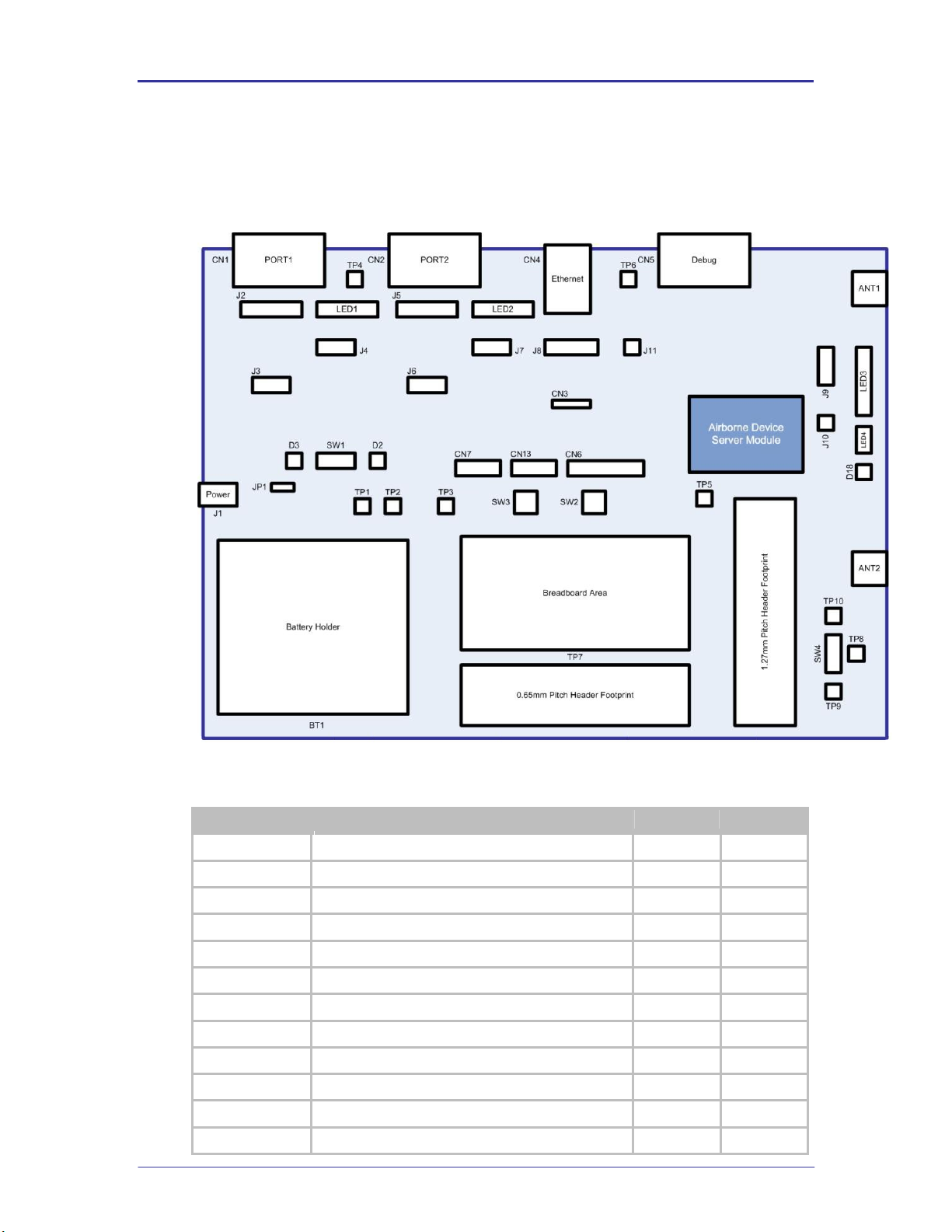
4.0 Evaluation Board Layout
FIGURE 1 - E VAL UAT ION BOARD L AYOUT
TABLE 2 - SU MMARY DESC RIP TION OF EVALUATION BO ARD
Page 13

B&B Electronics
Airborne Enterprise WLNN EVB Users Guide
13
Designator
Description
Ref
Page
D18
Radio association status indicator
5.13
19
J1
Power Connector (Barrel Jack)
5.14
19
J2
Primary UART port pin out configuration
5.15
20
J3
Primary UART port Transceiver enable
5.16
22
J4
Primary UART indicator LED header
5.17
23
J5
Secondary UART pin out configuration
5.18
24
J6
Secondary UART port Transceiver enable
5.19
26
J7
Secondary UART indicator LED header
5.20
27
J8
Ethernet termination
5.21
27
J9
Airborne Device Server Module status indicator LED
header
5.22 28
J10
GPIO indicator LED header
5.23
29
J11
Ethernet indicator LED’s
5.24
29
JP1
Power Source Selector
5.25
31
LED1
Primary UART port indicator LED’s
5.26
31
LED2
Secondary UART port indicator LED’s
5.27
31
LED3
Airborne Device Server Module status indicator LED’s
5.28
31
LED4
GPIO indicator LED’s
5.29
32
SW1
Evaluation board power switch
5.30
32
SW2
Evaluation board restart/reboot push button switch
5.31
32
SW3
Evaluation board factory default reset push button
switch
5.32 33
SW4
SPDT Switch
5.33
33
TP1
Input voltage
5.34
34
TP2
3.3VDC
TP3
GND
TP4
GND
TP5
GND
TP6
GND
TP7
Breadboard area
5.35
34
TP8
Common for SW4
5.36
36
TP9
L1 for SW4
TP10
L2 for SW4
Page 14

B&B Electronics
14
Airborne Enterprise WLNN EVB Users Guide
Designator
Connector
Description
CN9
RP-SMA
Antenna connection requires antenna with RP-SMA
connector.
Impedance: 50Ω
CN10
U.FL
Coaxial connector to Airborne Device Server antenna
connector. Requires U.FL to U.FL coaxial cable
(included in kit). Must be connected to either J1 or J2
of Device Server Module.
Impedance: 50Ω
Designator
Connector
Description
CN11
RP-SMA
Antenna connection requires antenna with RP-SMA
connector.
Impedance: 50Ω
CN12
U.FL
Coaxial connector to Airborne Device Server antenna
connector. Requires U.FL to U.FL coaxial cable
(included in kit). Must be connected to either J1 or J2.
Impedance: 50Ω
5.0 Feature Description
The following section provides detailed descriptions of the various connections, switches
and indicators provided by the Airborne Evaluation Board.
5.1 ANT1
This is one of two antenna connections available on the Evaluation board.
TABLE 3 - ANT1 CONNECT ORS
5.2 ANT2
This is one of two antenna connections available on the Evaluation board.
TABLE 4 - ANT2 CONNECT ORS
5.3 BT1
This section allows four (4) 1.5VDC Type AA cells to be installed and used to
power the evaluation kit for roaming and mobile tests.
To select the batteries as the Power Source use the correct setting for JP1.
A Low Battery status indicator is provided by D2.
Page 15

B&B Electronics
Airborne Enterprise WLNN EVB Users Guide
15
Designator
Connector
Description
CN1
DE-9 Male
Requires a DE-9 female connector. Depending upon
the configuration of J1 the following cable type should
be used:
DTE (Default): Straight through
DCE: Null Modem
Designator
Connector
Description
CN2
DE-9 Male
Requires a DE-9 Female connector. Depending upon
the configuration of J5 the following cable type should
be used:
DTE (Default): Straight through
DCE: Null Modem
5.4 CN1
This is the primary UART port and should be used for serial communication with
the card during initial evaluation. The pin out for the connector is managed by the
configuration of J2; it can support the following modes:
RS232 DTE
RS232 DCE
RS422/485 4-wire
RS422/485 2-wire
TABLE 5 - PR IMARY UART CO NNECTOR
5.5 CN2
This is the secondary UART port. This port can only be used if enabled via
firmware.
The pin out for the connector is managed by the configuration of J5; it can
support the following modes:
RS232 DTE
RS232 DCE
RS422/485 4-wire
RS422/485 2-wire
TABLE 6 - PR IMARY UART CO NNECTOR
5.6 CN3
This header provides direct connections to the Airborne Device Server module
Ethernet connections. The output of this header is provided by the embedded
Ethernet PHY built in to the Airborne Device Server module. Please refer to the
WLNN DP500 data book for details of this output.
This header allow for the implementation of external magnetic or a capacitive
coupled circuit between the Evaluation board and a test system. The pin out for
the header can be seen in Table 7.
Page 16
B&B Electronics
16
Airborne Enterprise WLNN EVB Users Guide
Designator
Pin
Description
CN3
1
TxD+
2
TxD- 3 RxD+
4
RxD-
Designator
Pin
Description
CN4
1
TxD+
2
TxD-
3
RxD+
4
NC 5 NC 6 RxD- 7 NC
8
NC
Green LED
Valid TCP/IP connection made with Airborne Device
Server:
Off No TCP/IP connection
On Valid TCP/IP Connection
Yellow LED
Power-on Self Test (POST):
Off Not powered or has failed POST
On Passed POST
TABLE 7 - ETHER NET PHY HE ADER PIN OUT
A detailed description of the Ethernet circuit on the Evaluation board can be
found in section 11.0.
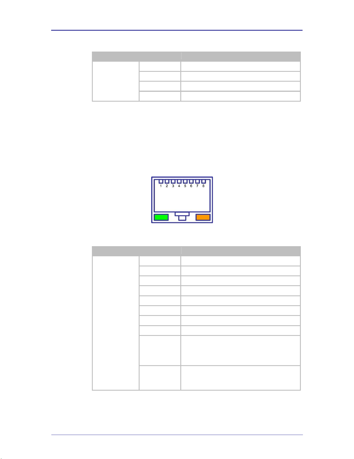
5.7 CN4
This connector is a 10/100 Ethernet RJ45 Jack with integrated magnetic. The pin
out is shown in Figure 2. It supports two integrated indicator LED’s, the conditions
for these indicators can be seen in Table 8.
FIGURE 2 - ETHE RNE T JA CK PIN OUT
TABLE 8 - ETHER NET CONNEC TOR PIN OUT
Page 17
B&B Electronics
Airborne Enterprise WLNN EVB Users Guide
17
Designator
Connector
Description
CN5
DE-9 Female
Requires a DE-9 Male connector. To connect to a
laptop or desktop serial port a straight thru cable is
required (included in kit).
Designator
Pin
Description
CN5
1
No Connect
2
D
OUT
3
D
IN
4
No Connect
5
GND
6
No Connect
7
No Connect
8
No Connect
9
No Connect
Designator
Pin
Description
CN6
1
3.3VDC
2
3.3VDC
3
NTRST: Test RESET
4
GND
5.8 CN5
This connector provides access to the serial debug port available on the Airborne
Serial Device Server module. The debug/console port is supported by a 2-wire
serial interface defined in Table 10. This port is a bidirectional serial port intended
for debug of the unit only; it does not support data transfer.
TABLE 9 - DE BUG PO RT CONN ECTOR
TABLE 10 - DE BUG PO RT PIN OUT
5.9 CN6
This header provides connectivity to the JTAG interface available on the Airborne
Device Server Module. The pin out for the header can be seen in Figure 3 and
Table 11.
FIGURE 3 - J TAG HEADER
The default settings for the debug port are 115200, 8, N 1, No Flow Control.
TABLE 11 - JT AG HEADER PIN OUT
Page 18
B&B Electronics
18
Airborne Enterprise WLNN EVB Users Guide
Designator
Pin
Description
5
TDI: Test Data In
6
GND 7 TMS: Test Mode Select
8
GND
9
TCK: Test Clock
10
GND
11
RTCK: Return Test Clock
12
GND
13
TDO: Test Data Out
14
GND
15
/RESET (Active Low)
16
GND
17
No Connect
18
GND
19
No Connect
20
GND
Designator
Pin
Description
CN7
1
No Connect
2
GND
Use of this header requires that JTAG has been enabled on the Airborne Device Server
Module. Production devices do not support this feature.
To enable JTAG a hardware change to the module must be made, please contact
B&B Electronics Technical Support if this feature is required.
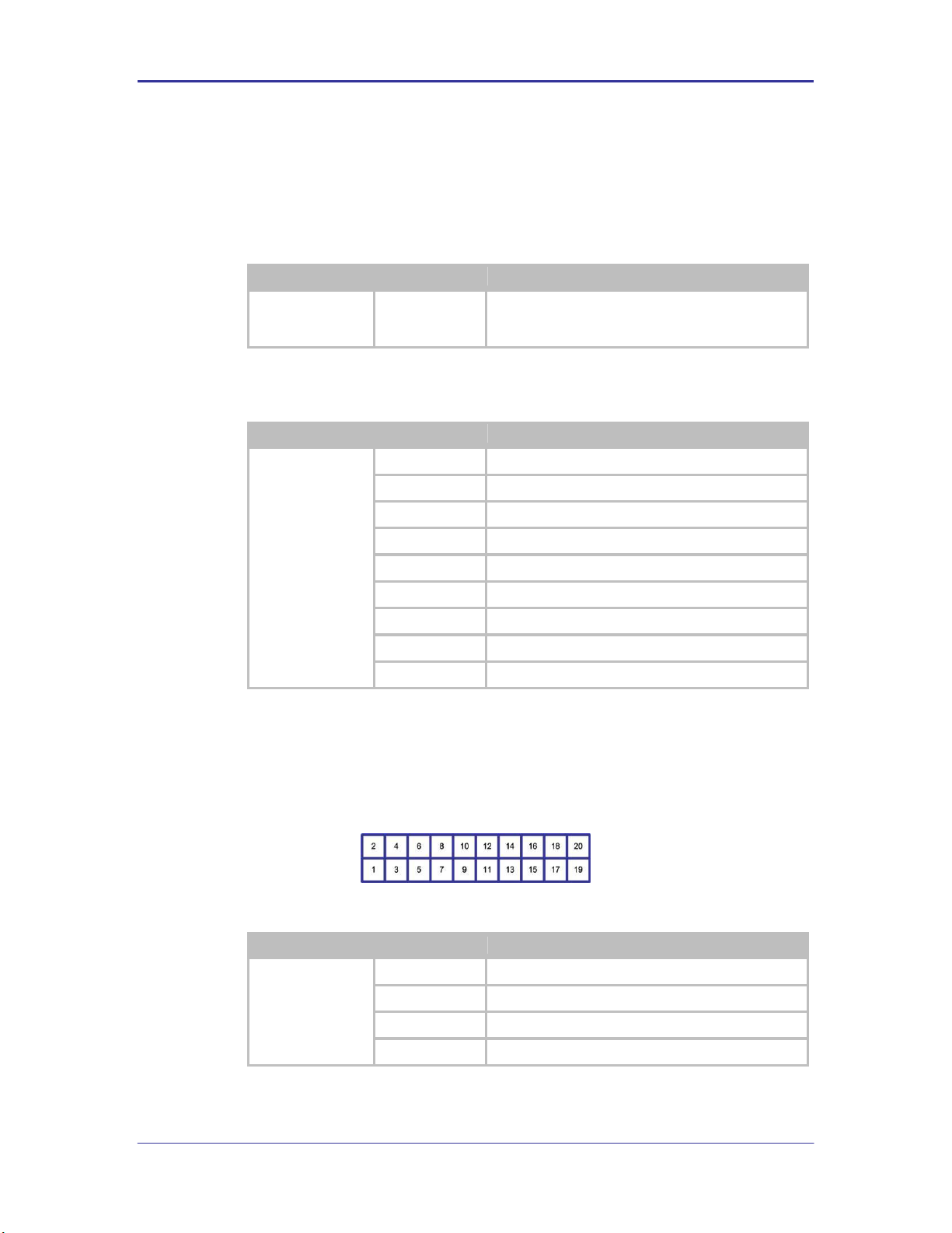
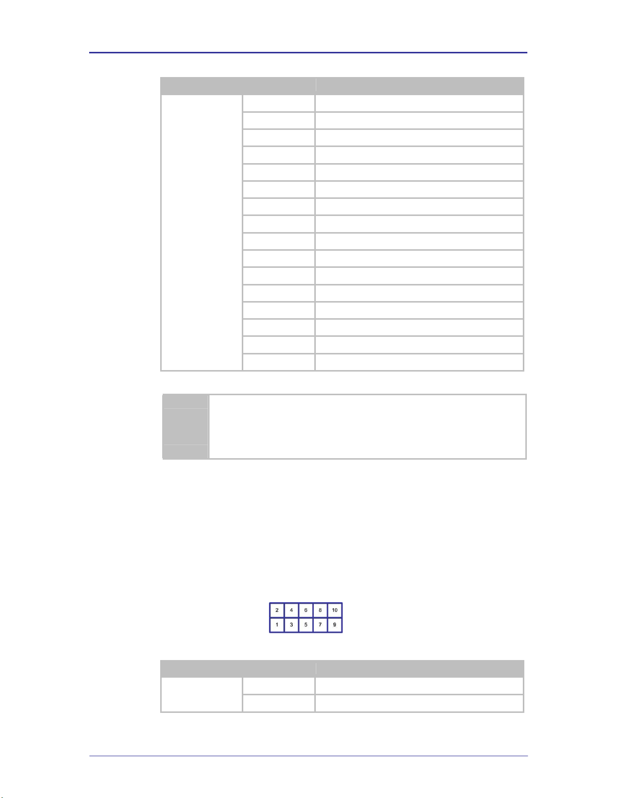
5.10 CN7 / CN13
Header CN7 is the primary SPI interface header; firmware selection of the SPI
interface is required before the interface can be used. CN13 allows a secondary
connection to the SPI interface. CN7 and CN13 have common connections.
The header pin out can be seen in Figure 4 and Table 12.
FIGURE 4 - S PI HEADER
TABLE 12 - SP I H EADER P IN OUT
Page 19

B&B Electronics
Airborne Enterprise WLNN EVB Users Guide
19
Designator
Pin
Description
3
No Connect
4
No Connect
5
MISO: D
OUT
6
No Connect
7
SPI_CLK: SPI Clock
8
MOSI: D
IN
9
SPI_SEL: SPI Select
10
GND
Designator
Status
Description
D2
ON
Power supply is 3.3VDC or less
OFF
Power supply is above minimum voltage
Designator
Status
Description
D3
ON
Power supplied to the card, SW1 on ON position
OFF
No power supplied to the card, SW1 on OFF position
Designator
Status
Description
D18
OFF
No valid Power to the module
BLINKING
Searching for valid SSID
ON
Associated with valid SSID
5.11 D2
This is a red indicator LED that provides feedback on the voltage level of the
power supply. This indicator will light when a low voltage state is detected.
TABLE 13 - LO W V OLTAGE LED INDI CAT OR
5.12 D3
This is a green indicator LED that provides feedback on the power status of the
Evaluation board.
TABLE 14 - POWER STATUS LED I NDICA TOR
5.13 D18
This indicator LED provides feedback on the association status of the radio. The
indicator is provided by the RF_ACT output of the Airborne Device Server
module.
TABLE 15 - RF ACTIVITY LED INDICATOR
5.14 J1
This is the main power jack for the Evaluation board. It requires a 5VDC/1.0A
minimum supply (supplied with kit).
Page 20

B&B Electronics
20
Airborne Enterprise WLNN EVB Users Guide
Designator
Connector
Description
J1
2.1mm Barrel
Jack
5.0VDC +/-10%, 1.00A minimum.
Designator
Configuration
Header
Pin Out
J2
RS232 DTE
(Default)
1
No Connect
2
RxD
3
TxD 4 No Connect
5
GND 6 No Connect
7
RTS 8 CTS
9
No Connect
TABLE 16 - POWER SUP PLY JACK
5.15 J2
This header configures the Primary UART port connector (CN1), selection of the
headers allows the connector pin-out to be changed to support one of the
following configurations:
RS232 DTE
RS232 DCE
RS422/485 4-wire
RS422/485 2-wire
For each of the configurations please note there is a pin out change and it may
be necessary to alter the cable being used for connection to the serial host. The
different configurations of jumpers and pin outs can be seen in Table 17.
It is not possible to independently select the transceiver type for each UART port
(CN1 and CN2) consequently both ports must be the same type (RS232 or
RS422/485).
FIGURE 5 - DE-9 CONNE CTOR PI N -OUT
TABLE 17 - PR IMARY U ART PIN -OUT HE ADER CO NFI GURA TION
Page 21

B&B Electronics
Airborne Enterprise WLNN EVB Users Guide
21
Designator
Configuration
Header
Pin Out
RS232 DCE
1
No Connect
2
TxD
3
RxD 4 No Connect
5
GND 6 No Connect
7
CTS 8 RTS
9
No Connect
RS422/485 2-Wire
1
No Connect
2
No Connect
3
TxD+
4
No Connect
5
GND 6 No Connect
7
No Connect
8
No Connect
9
TxD-
RS422/485 4-Wire
1
No Connect
2
RxD+
3
TxD+
4
No Connect
5
GND 6 RxD- 7 No Connect
8
No Connect
9
TxD-
Designator
Pin
Description
J2
1
RxD+
2
TxD+
3
CN1 Pin 2
FIGURE 6 - P RIMARY UART H EADE R
TABLE 18 - PR IMARY UART HEADE R PIN -OUT
Page 22

B&B Electronics
22
Airborne Enterprise WLNN EVB Users Guide
Designator
Pin
Description
4
RxD
5
TxD 6 CN1 Pin 3
7
TxD-
8
TxD+
9
CN1 Pin 9
10
CN1 Pin 6
11
TxD-
12
RxD-
13
CN1 Pin 8
14
CTS
15
RTS
16
CN1 Pin 7
Designator
Description
Configuration
J3
RS232
RS422/485
Software Select
Designator
Pin
Description
J3
1
RS422/485 Rx Enable (Active Low)
2
RXEN
3
GND
4
RS232 Rx Enable (Active Low) with 10KΩ Pull-up
5
3.3VDC
5.16 J3
This header correctly enables the primary UART transceivers for the interface
type selected by the configuration of J2. The available options are shown in
Table 19.
TABLE 19 - PR IMARY UART TRANSCEIVE R CONF IGUR ATIO N
FIGURE 7 - P RIMARY UART T RANSCEIV ER HEADER
TABLE 20 - PR IMARY UART TRANSCEIVE R HEADE R PIN-O UT
Page 23

B&B Electronics
Airborne Enterprise WLNN EVB Users Guide
23
Designator
Pin
Description
6
SER_MODE
7
RS422/485 Tx Enable (Active High)
8
/TXEN (Active Low)
Designator
Pin
Description
J4
1
RxD (EVB Signal Driver), D4 (Red LED)
2
RxD (Airborne Device Server Module)
3
TxD (EVB Signal Driver), D5 (Red LED)
4
TxD (Airborne Device Server Module)
5
CTS (EVB Signal Driver), D6 (Yellow LED)
6
CTS (Airborne Device Server Module)
7
RTS (EVB Signal Driver), D7 (Green LED)
8
RTS (Airborne Device Server Module)
Signal RXEN (Pin 2), SER_MODE (Pin 6) and /TXEN (Pin 8) are sourced from the
Airborne Device Server module, please refer to the WLNN DP500 data book for a
description of these signal.
5.17 J4
This header provides access to the Primary UART LED status indicators.
The default has all LED’s connected.
FIGURE 8 - P RIM ARY UART L ED I NDIC ATOR HE ADE R
TABLE 21 - PR IMARY U ART LED IND ICATOR HEA DER PIN -OUT
Removing the jumpers from this header will disconnect the signals to the Primary UART
connector CN1.
Signals on Pins 1, 3, 5 and 7 are sourced directly from the Airborne Device Server
module and are not buffered or driven by the Evaluation board.
Page 24

B&B Electronics
24
Airborne Enterprise WLNN EVB Users Guide
Designator
Configuration
Header
Pin Out
J5
RS232 DTE
(Default)
1
No Connect
2
RxD 3 TxD 4 No Connect
5
GND 6 No Connect
7
RTS
8
CTS 9 No Connect
RS232 DCE
1
No Connect
2
TxD 3 RxD 4 No Connect
5
GND
6
No Connect
7
CTS
5.18 J5
This header configures the Secondary UART port connector (CN2), selection of
the headers allows the connector pin-out to be changed to support one of the
following configurations:
RS232 DTE
RS232 DCE
RS422/485 4-wire
RS422/485 2-wire
For each of the configurations please note there is a pin out change and it may
be necessary to alter the cable being used for connection to the serial host. The
different configurations of jumpers and pin outs can be seen in Table 22.
It is not possible to independently select the transceiver type for each UART port
(CN1 and CN2) consequently both ports must be the same type (RS232 or
RS422/485).
FIGURE 9 - DE-9 CONNE CTOR PI N -OUT
TABLE 22 - SE CON DARY UART PIN-OUT HEADER CONFIG U RATION
Page 25

B&B Electronics
Airborne Enterprise WLNN EVB Users Guide
25
Designator
Configuration
Header
Pin Out
8
RTS
9
No Connect
RS422/485 2-Wire
1
No Connect
2
No Connect
3
TxD+
4
No Connect
5
GND 6 No Connect
7
No Connect
8
No Connect
9
TxD-
RS422/485 4-Wire
1
No Connect
2
RxD+
3
TxD+
4
No Connect
5
GND
6
RxD- 7 No Connect
8
No Connect
9
TxD-
Designator
Pi
n
Description
J2
1
RxD+
2
TxD+
3
CN1 Pin 2
4
RxD 5 TxD
6
CN1 Pin 3
7
TxD-
8
TxD+
9
CN1 Pin 9
FIGURE 10 - SE CONDARY UA RT HEAD E R
TABLE 23 - PR IMARY UART HEADE R PIN -OUT
Page 26

B&B Electronics
26
Airborne Enterprise WLNN EVB Users Guide
Designator
Pi
n
Description
10
CN1 Pin 6
11
TxD-
12
RxD-
13
CN1 Pin 8
14
CTS
15
RTS
16
CN1 Pin 7
Designator
Description
Configuration
J6
RS232
RS422/485
Software Select
Designator
Pin
Description
J6
1
RS422/485 Rx Enable (Active Low)
2
RXEN
3
GND 4 RS232 Rx Enable (Active Low) with 10KΩ Pull-up
5
3.3VDC
6
SER_MODE
7
RS422/485 Tx Enable (Active High)
8
/TXEN (Active Low)
5.19 J6
This header correctly enables the Secondary UART transceivers for the interface
type selected by the configuration of J5. The available options are shown in Table
25.
TABLE 24 - SE CON DARY UART T RANSCEI VER CONFIG URATION
FIGURE 11 - SE CONDARY UA RT T RAN S CEIVER HEA DER
TABLE 25 - SE CON DARY UART T RANSCEI VER HEA DER PIN -OUT
Page 27

B&B Electronics
Airborne Enterprise WLNN EVB Users Guide
27
Designator
Pin
Description
J4
1
RxD (EVB Signal Driver), D4 (Red LED)
2
RxD (Airborne Device Server Module)
3
TxD (EVB Signal Driver), D5 (Red LED)
4
TxD (Airborne Device Server Module)
5
CTS (EVB Signal Driver), D6 (Yellow LED)
6
CTS (Airborne Device Server Module)
7
RTS (EVB Signal Driver), D7 (Green LED)
8
RTS (Airborne Device Server Module)
Signal RXEN (Pin 2), SER_MODE (Pin 6) and /TXEN (Pin 8) are sourced from the
Airborne Device Server module, please refer to the WLNN DP500 data book for a
description of these signal.
5.20 J7
This header provides access to the Secondary UART LED status indicators.
The default has all LED’s connected.
FIGURE 12 - SE CONDARY UA RT L ED I NDI C ATO R HEADER
TABLE 26 - SE CON DARY UART L ED I NDI CATOR HEAD ER PIN-O UT
Removing the jumpers from this header will disconnect the signals to the Secondary
UART connector CN2.
Signals on Pins 1, 3, 5 and 7 are sourced directly from the Airborne Device Server
module and are not buffered or driven by the Evaluation board.
5.21 J8
This header controls the access to the Ethernet interface. The options available
for this header can be seen in Table 27.
Page 28

B&B Electronics
28
Airborne Enterprise WLNN EVB Users Guide
Designator Descripti
on
Configuration
J8 Ethernet Jack (Default)
CN3 Header
Designator
Pin
Description
J8
1
CN3 Pin 3
2
CN3 Pin 1
3
RxD+ (Airborne Device Server)
4
TxD+ (Airborne Device Server)
5
RxD+ (CN4)
6
TxD+ (CN4)
7
CN3 Pin 4
8
CN3 Pin 2
9
RxD- (Airborne Device Server)
10
TxD- (Airborne Device Server)
11
RxD- (CN4)
12
TxD- (CN4)
TABLE 27 - ETHER NET HEA DER CO NFIGURATION
This header provides direct connections to the Airborne Device Server module
Ethernet connections. The output of this header is provided by the embedded
Ethernet PHY built in to the Airborne Device Server module. Please refer to the
WLNN DP500 data book for details of this output.
TABLE 28 - ETHER NET HEA DER PIN - OUT
5.22 J9
This header provides access to the status indicators generated by the Airborne
Device Server module. The header provides a connection to the on board LED’s
in the LED3 section 5.28.
The default has all LEDs connected.
FIGURE 13 – AI RBO RNE DEVICE SER VER MODULE STATUS IND I CATOR HEAD ER
Page 29

B&B Electronics
Airborne Enterprise WLNN EVB Users Guide
29
Designator
Pin
Description
J9
1
D12 (POST LED)
2
LED_POST (Airborne Device Server Module)
3
D13 (RF_LINK LED)
4
LED_RF_LINK (Airborne Device Server Module)
5
D14 (WLN_CFG LED)
6
LED_CFG_WLN (Airborne Device Server Module)
7
D15 (CONN LED)
8
LED_CON (Airborne Device Server Module)
Designator Descripti
on
Configuration
J10
LED’s Connected
LED’s Disconnected
Designator
Pin
Description
J10
1
D16 (Yellow)
2
Port G0 (Airborne Device Server Pin 22)
3
D17 (Yellow)
4
Port G1 (Airborne Device Server Pin 19)
TABLE 29 - AI RBO RNE DEV ICE SERVER MODULE STATUS IND I CAT OR HEAD ER PIN-OUT
Signals on Pins 2, 4, 6 and 8 are sourced directly from the Airborne Device Server
module and are not buffered or driven by the Evaluation board.
5.23 J10
This header allows GPIO pins sourced from the Airborne Device Server module
to be connected to LED’s on the Evaluation board. These indicators can be used
to demonstrate control of the G0 and G1 ports via the CLI or web interface.
FIGURE 14 - GP IO LED HEA DER
5.24 J11
TABLE 30 - GPIO LED HEA DER CON F IGURATION
TABLE 31 - GPIO LED HEA DER PIN - OUT
This header connects the Airborne Device Server module sources indicator
signals to the Ethernet jack. A description of the signals can be seen in section
5.7.
Page 30

B&B Electronics
30
Airborne Enterprise WLNN EVB Users Guide
Designator Descripti
on
Configuration
J11
LED’s Connected (Default)
LED’s Disconnected
Designator
Pin
Description
J11
1
CN4 (Green LED)
2
LED_CON (Airborne Device Server Pin 23)
3
CN4 (Yellow LED)
4
Port F0 (Airborne Device Server Pin 25)
Designator Descripti
on
Configuration
JP1
External power Supply.
This selects J1 (5.14) as the source for
power.
Battery power.
This selects BT1 (5.3) as the source for
power.
Group
Pin
Description
JP1
1
J1 external 2.1mm Barrel jack.
2
EVB Power Supply Input
3
BT1 4 x AA cell holder
FIGURE 15 – ET HERNET INDICATOR LED HEADER
TABLE 32 – ET HERNET IND ICATOR L ED HEADER CONFIGU RAT IO N
TABLE 33 – ET HERNET INDICATOR LED HEADER PIN-OUT
5.25 JP1
This jumper provides the ability to select the power source for the Evaluation
Board. The options can be seen in Table 34.
FIGURE 16 - JP 1 PI N-O UT
TABLE 34 - POWER SOU RCE SEL ECT O R
TABLE 35 - JP 1 P OWER SE LECTOR P IN-OUT
Page 31

B&B Electronics
Airborne Enterprise WLNN EVB Users Guide
31
Group
Designator
Description
LED1
D7
Ready to Send (RTS), Green LED
D6
Clear-to-Send (CTS), Yellow LED
D5
Transmit Data (TxD), Red LED
D4
Receive Data (RxD), Red LED
Group
Designator
Description
LED2
D11
Ready to Send (RTS), Green LED
D10
Clear-to-Send (CTS), Yellow LED
D9
Transmit Data (TxD), Red LED
D8
Receive Data (RxD), Red LED
Group
Designator
Name
Description (w/ Power Applied)
LED3
D15
CONN
(Green)
OFF
No TCP/IP connection established
ON
TCP/IP connection established with Device
Server
D14
WLN_CFG
(Yellow)
OFF
The Device Server is not correctly
configured for network communication
(i.e. it does not have a valid IP
address/subnet mask)
ON
The Device Server is correctly configured
for network communication (i.e. it has a
valid IP address/subnet mask)
D13
RF_LINK
(Green)
OFF
Device Server has not authenticated with
a wireless network
ON
Device Server has successfully
authenticated with a wireless network
5.26 LED1
This is a group of LED’s that indicate Primary UART’s state of operation. A
description of the LED’s can be seen in Table 36. These LED’s are connected via
J4 (section 5.17), please refer to this section for more details.
TABLE 36 - PR IMARY UART IN DICATOR LED 'S
5.27 LED2
This is a group of LED’s that indicate Secondary UART’s state of operation. A
description of the LED’s can be seen in Table 37. These LED’s are connected via
J7 (section 5.20), please refer to this section for more details.
TABLE 37 - SE CON DARY UA RT INDIC ATO R L ED'S
5.28 LED3
This is a group of LED’s that indicate the state of the Airborne Device Server
module. A description of the LED’s can be seen in Table 38. These LED’s are
connected via J9 (section 5.22), please refer to this section for more details.
TABLE 38 – AI RBORNE DEV ICE SER V ER MODULE INDICATOR L ED’S
Page 32

B&B Electronics
32
Airborne Enterprise WLNN EVB Users Guide
Group
Designator
Name
Description (w/ Power Applied)
D12
POST
(Yellow)
OFF
Passed Power-on-Self-Test
ON
Failed Power-on-Self-Test
Group
Designator
Description
LED4
D17
G1 (Yellow LED)
D16
G0 (Yellow LED)
A more detailed description of these status indicators can be seen in section
13.0.
5.29 LED4
This group of LED’s is available for use. They can be connected to and driven by
GPIO G0 and G1, via the CLI of the Airborne Device Server module. It is possible
to demonstrate I/O control using this combination.
They can be connected to the GO and G1 ports via J10 (section 5.23). Please
refer to this section for more details.
TABLE 39 - LED4 DESCRIP TION
5.30 SW1
This is the main power switch for the evaluation board. A valid power supply
(included with kit) must be connected to J1 and JP1 must be configured for an
external power supply (default set-up) or BT1 must have a valid set of cells and
JP1 must be configured for Batteries before the switch is enabled.
If a valid power source is attached, D3 (section 5.12) will light. This will indicate
the start of the Airborne Device Server boot cycle. The cycle may take several
seconds; please allow enough time to complete the boot cycle before resetting
the switch.
When the Airborne Device Server boot successfully you will see the POST
(section 5.28) and RF_ACT LED (section 5.28) indicators light.
FIGURE 17 - SW 1 SET-UP
5.31 SW2
This push button switch restarts or reboots the Airborne Device Server module. If
pressed for more than 100ms the module will initiate an internal power-on restart
cycle. This switch is connected to pin 7 (/RESET) pin of the module; please refer
to the WLNN DP500 Data-book for more details.
The /RESET behavior is not the same as a Power-on-restart; please refer to the
WLNN DP500 Data-book for details.
Page 33

B&B Electronics
Airborne Enterprise WLNN EVB Users Guide
33
FIGURE 18 - SW 2 RESET CIRCUIT
5.32 SW3
This push button switch allows the user to reset the Airborne Device Server
module settings back to OEM default. The button cannot reset settings by itself; it
requires either a power cycle or restart.
To reset the module configuration back to OEM defaults SW3 must be pushed
and held while the restart or power cycle is initiated. It is required that SW3 be
held for approximately 3 seconds after the restart or power cycle has been
initiated, it can then be released. The module will then continue the boot cycle
and the OEM parameter values will be reinstalled.
FIGURE 19 - OE M RESET CI RCUIT
Doing an OEM reset will reset all parameters back to OEM default values; this may
place the module in a state that will not allow the user to communicate with it.
IMPORTANT: Confirm that the OEM settings installed on the module will allow the
user to communicate with the module after the reset has been completed.
5.33 SW4
This is an additional SPDT switch that may be used in conjunction with the test
points (TP7, 8, 9, 10) to demonstrate functionality provided by the Airborne
Device Server module.
FIGURE 20 - SW 4 CO NFI GURATION
Page 34

B&B Electronics
34
Airborne Enterprise WLNN EVB Users Guide
Group
Designator
Description
Test Point
TP1
Input Voltage: This test point provides access to the
input voltage on J1.
TP2
3.3VDC: This test point provides access to the
regulated power supply output.
TP3
GND
TP4
GND
TP5
GND
TP6
GND
5.34 TP1 – 6
Included on the Evaluation board is a number of test points; these are available
for use by the user when evaluating or developing with the evaluation board. The
set of test points provide measurement or sourcing points for the various power
and ground options available on the board; Table 40 indicates the test point
function.
TABLE 40 - TP1-6 CON FIG URAT ION
5.35 TP7
This section of the Evaluation board provides space for development of prototype
application hardware directly on the board. The matrix provides access to the full
interface of the Airborne Device Server module as well as an ample supply of
power and ground signals.
Since the signal definition could change depending upon the type of module
being used (UART, Serial, SPI, Ethernet) details of the signals and their
characteristics can be found in the WLNN DP500 Data book. A translation of
prototype area (TP7) designator to WLNN pin out can be seen in Table 41.
FIGURE 21 - TP7 LAYOUT
Page 35

B&B Electronics
Airborne Enterprise WLNN EVB Users Guide
35
TP7 Designator
WLNN Pin
+3.3V
3, 4, 33, 34
VIN
CGND
GND
1, 15, 16, 36
G7
21
G6 9 G2
17
G1
19
F1
28
F7
24
F4
18
F5
12
G0
22
DTXD
6
DRXD
8
/FRESET
11
/RESET
7
NTRESET
31
TDO
10
TDI 2 TCK
20
RTCK
5
TMS
32
TX+
30
TX-
29
RX+
13
RX-
14
F0
25
F2
27
F3
26
F6
23
/RF_ACT
35
TABLE 41 - TP7 LABEL TO WL NN P I N-O UT T ABL E
Page 36

B&B Electronics
36
Airborne Enterprise WLNN EVB Users Guide
5.36 TP8 - 10
These test points have bee n made available for prototyping using the Evaluation
board; they are connected to SW4 (section 5.33). Please refer to this section for
detail.
6.0 A Typical Development System
It is necessary to have additional equipment to get the most out of the Airborne™
Evaluation board and fully experience the power of the Airborne™ Device Server module.
A typical evaluation system includes:
A host computer that communicates with the Airborne Device Server module, the
interface options are:
WLNN-EK-DP501 via the EVB RS-232 interface (PORT 1, CN1)
WLNN-EK-DP502 via the EVB SPI interface (CN7)
WLNN-EK-DP503 via the EVB RJ-45 interface (ETHERNET, CN4)
A host computer that communicates with the Airborne Device Server module via
the network interface.
An IEEE-compliant 802.11b/g/n or 802.11a/n AP (or a Wireless Router) for
A DHCP server (this may be resident in the Wireless Router).
which you know the association and authentication settings.
A terminal emulation program like HyperTerminal, PuTTy or TerraTerm
Page 37

B&B Electronics
Airborne Enterprise WLNN EVB Users Guide
37
7.0 Getting Started
7.1 Unpack the Airborne™ Module EVB Kit
Unpack the Airborne Device Server Module EVB and compare the package
contents with the items listed on the front of this User Guide. If any item is
missing or damaged, contact B&B Electronics immediately.
7.2 Attach Antenna and Power-up the EVB
7.3 Install Serial to USB Adapter (Optional)
7.4 Connection to SPI Host
The Evaluation kit contains the following items:
One Airborne™ Device Server Module Evaluation Circuit Board
Assembly (EVB)
One WLNN-XX-DP501 module (mounted on the EVB)
Two monopole Antennas (2dBi RP-SMA)
One AC adapter (5VDC/500mA)
One DB9-to-DB9 serial cable (Null Modem)
USB to serial Adapter (SSU2-100)
One CD containing drivers, evaluation software, PDF documents, and
Adobe® Acrobat® Reader® for viewing the documents
Contact details can be found at http://www.bb-elec.com/Tech-Support.aspx
Attach the supplied antenna to connector CN11 on the EVB. Connect the
supplied AC adapter to the power (J1) connector on the Airborne EVB. Confirm
that the EVB is receiving power by verifying that the Power LED (D3) is lit when
POWER (SW1) is in the ON position.
If your host computer does not have a RS232 port the Evaluation Kit includes a
USB to Serial adapter (SSU2-100). This adapter provides the ability to connect
using a virtual serial port on the host to the EVB. Please refer to the enclosed CD
and documentation for the installation of the adapter.
To connect and communicate with the EVB it will be necessary for an SPI based
host to comply with the SPI host interface specification outlined in the WLNN
DP500 Databook, please refer to this document before connecting an SPI host.
Page 38

B&B Electronics
38
Airborne Enterprise WLNN EVB Users Guide
CLI Command
Description
auth dpac dpac <CR>
The module responds with OK, indicating that it
executed the command successfully. (If you did not
receive OK, check the settings in your terminal
emulation program.
8.0 Serial Device Server Connection
If you have purchased the WLNN-EK-DP501 or WLNN-EK-DP502 kit please use the
following instructions for connecting to and evaluating the Airborne Serial Device Server.
The following describes initial connection to an Airborne Device Server module loaded
with UART (WLNN-AN-DP501) firmware; if you have a module loaded with Ethernet
(WLNN-ER-DP501) firmware, please skip to section 9.0.
8.1 Connect a Host Computer
Use the supplied serial cable or USB adapter (see USB-to-Serial Adapter User’s
Manual for USB adapter installation) to connect the DB9 serial port (CN1)
connector on the Airborne EVB to the Host computer. On the Host
start
a terminal emulation program such as HyperTerminal. Configure
program
for 9600 baud, 8 data bits, no parity, and no flow control. For COM Port,
select the COM port that corresponds to the host’s physical serial port connected
to the EVB (or in the case of the USB adapter, the virtual COM port created
the
adapter software).
If supplying your own cable when connecting to the Evaluation Kit please confirm it
supports the default configuration (female DE-9, DCE) for connection to the
Evaluation kit.
If you are unable to connect to the kit please refer to sections 5.4, 5.15 and 5.16 for
details on the Evaluation kit CN1 requirements.
8.2 Interacting with the Airborne™ Module
On the Host computer, use the terminal emulation program to interact with the
module by issuing Command Line Interface (CLI) commands. CLI commands let
you request status or change parameter settings. Press the Enter key (<CR>)
after each command line you type. After the module starts, type the following CLI
command to log in (you must log in before CLI commands can be recognized):
TABLE 42 - UA RT AUTHENT ICATION
computer,
the
by
You will have to log into the module after any reset or restart.
Page 39

B&B Electronics
Airborne Enterprise WLNN EVB Users Guide
39
CLI Command
Description
wl-scan<CR>
The module scans for APs and returns information on
each one it discovers. Note the SSID value that is
returned, as you will need to enter it in the next
command
wl-ssid [SSID]<CR>
Associates the module with the AP whose [SSID] you
specify. [SSID] is the value returned by the wl-scan
command.
commit<CR>
Stores the information to flash memory.
CLI Command
Description
auth dpac dpac <CR>
Authenticate with the device server.
wl-ip<CR>
The module returns the IP address assigned to it by
the DHCP server.
8.3 Determine and Store the Access Point SSID
On the Host computer, use the terminal emulation program to type the following
CLI commands in the order shown:
TABLE 43 - UA RT SSID & AUT HENTI CAT ION
If your acc ess point has security enabled, you will also need to use the CLI to
enter those parameters (See the Enterprise CLI Reference Guide for details).
That setup is outside the scope of this user guide, which assumes that the AP
being tested with has no security.
After issuing the commands, press the reset switch (SW2) on the EVB. The EVB
restarts and the RF_ACT LED blinks to show that the module is searching for an
AP. Once the module has found and associated to the AP entered using the wl-
ssid command the RF_ACT LED will turn on continuously.
8.4 Determine the Module’s IP address
On the Host computer, use the terminal emulation program to type the following
CLI commands:
TABLE 44 - UA RT DET E RMI NE MODUL E'S IP ADD RES S
8.5 Accessing the Module Using Telnet
On the Remote computer, use HyperTerminal to start a Telnet session. In the
first screen, name the session ‘TCP <Module IP>’ (for reference purposes only),
click on any icon you want to associate with this Telnet session, and click OK. In
the next screen, click TCP/IP (Winsock) for Connect Using. In the Host Address
field, type the module’s IP address. Leave the default Port Number value of 23
and click OK.
The HyperTerminal application will then attempt to open a TCP session with the
module, Connecting is shown in the status bar at the bottom-left side of the
screen as HyperTerminal tries to make the Telnet connection. When the
connection is made, Connecting is replaced by Connected. You can know
interact with the Airborne Device Server, to authenticate with the module type
auth dpac dpac<CR>.
Page 40

B&B Electronics
40
Airborne Enterprise WLNN EVB Users Guide
After the connection is authenticated you can enter CLI commands e.g. type wlinfo to view basic information on the module.
For more information on the full CLI command set please refer to the Command
Line Reference Manuals.
The above process can be achieved by any of the available Terminal Emulation
programs. Please follow the specific applications requirements to make the TCP/IP
connection and authenticate with the module.
Page 41

B&B Electronics
Airborne Enterprise WLNN EVB Users Guide
41
CLI Command
Description
auth dpac dpac <CR>
The module responds with OK, indicating that it
executed the command successfully. (If you did not
receive OK, check the settings in your terminal
emulation program.
9.0 Ethernet Bridge Connection
If you have purchased the WLNN-EK-DP503 kit, please use the following instructions for
connecting to and evaluating the Airborne Ethernet Bridge Module.
9.1 Connect a Host Computer
Using a Cat5 cable, connect the RJ45 port (CN4) connector on the Airborne EVB
to the Ethernet port on the Host computer. First make sure the Host PC has
IP
address of its Ethernet port set to be assigned by DHCP or assigned a static
address of 192.168.2.100.
9.2 Interacting with the Airborne™ Module
On the Host computer, use HyperTerminal to start a Telnet session. In the first
screen, name the session Wired Telnet (for reference purposes only), click on
any icon you want to associate with this Telnet session, and click OK. In the next
screen, click TCP/IP (Winsock) for Connect Using. In the Host Address field,
enter the IP address 192.168.2.1. Leave the default Port Number value of 23 and
click OK. Use the terminal emulation program to interact with the module by
issuing command Line Interface (CLI) commands. CLI commands let you request
status or change parameter settings. Press the Enter key
command line you type. After the module starts, type the following CLI command
to log in (You must log in before CLI commands can be recognized):
TABLE 45 - ETHER NET AUT HENT ICA T ION
(
<CR>)
the
after each
You will have to log into the module after any reset or restart
Page 42

B&B Electronics
42
Airborne Enterprise WLNN EVB Users Guide
CLI Command
Description
wl-scan<CR>
The module scans for APs and returns information on
each one it discovers. Note the SSID value that is
returned, as you will need to enter it in the next
command
wl-ssid [SSID]<CR>
Associates the module with the AP who’s [SSID] you
specify. [SSID] is the value returned by the wl-scan
command.
commit<CR>
Stores the information to flash memory.
CLI Command
Description
auth dpac dpac <CR>
Authenticate with the firmware
wl-ip<CR>
The module returns the IP address assigned to it by the
DHCP server.
9.3 Determine and Store the Access Point SSID
On the Host computer, use the terminal emulation program to type the following
CLI commands in the order shown:
TABLE 46 - ETHER NET SSI D & AUT HENT ICATION
If your access point has security enabled, you will also need to use the CLI to
enter those parameters (See the CLI Reference Guide for details). That setup is
outside the scope of this user guide, which assumes that the AP being used has
no security.
After issuing the commands, press the reset switch (SW2) on the EVB. The EVB
restarts and the RF_ACT LED turn on solid to show that the module has
connected to the AP. You will need to reconnect the Telnet session after each
reset or restart.
9.4 Determine the Module’s IP address
On the Host computer, use the terminal emulation program to type the following
CLI commands:
TABLE 47 - ETHERNET D ETE RMINE M O DULES I P A DDRESS
9.5 Accessing the Module Using Telnet
On the Remote computer, use HyperTerminal to start a Telnet session. In the
first screen, name the session ‘TCP <Module IP>’ (for reference purposes only),
click on any icon you want to associate with this Telnet session, and click OK. In
the next screen, click TCP/IP (Winsock) for Connect Using. In the Host Address
field, type the module’s IP address. Leave the default Port Number value of 23
and click OK.
Page 43

B&B Electronics
Airborne Enterprise WLNN EVB Users Guide
43
The HyperTerminal application will then attempt to open a TCP session with the
module, Connecting is shown in the status bar at the bottom-left side of the
screen as HyperTerminal tries to make the Telnet connection. When the
connection is made, Connecting is replaced by Connected. You can know
interact with the Airborne Device Server, to authenticate with the module type
auth dpac dpac<CR>.
After the connection is authenticated you can enter CLI commands e.g. type wl-
info to view basic information on the module.
For more information on the full CLI command set please refer to the Command
Line Reference Manuals.
The above process can be achieved by any of the available Terminal Emulation
programs. Please follow the specific applications requirements to make the TCP/IP
connection and authenticate with the module.
Page 44

B&B Electronics
44
Airborne Enterprise WLNN EVB Users Guide
10.0 Using the Web Interface
The Airborne Device Server includes a web interface that provides access to module
status, parameter modification and certificate and configuration file management. To use
the web interface follow the steps outlined in section 8.0 to establish the IP address of the
module. Once the IP address is known open a web browser and enter the IP address of
the module in the URL window.
The web interface currently supports Internet Explorer v6.0 thru 8.0, Firefox v3.x, Opera
v9.6+ and Chrome v1.0+.
When the authentication request is returned enter:
FIGURE 22 - WE BSITE L OGI N
Username:
Password:
dpac
dpac
After successfully authenticating with the module, you will be logged into the web server
and allowed to browse and update module settings if required. A quick overview of the
web interface follows.
10.1 Navigation Bar
FIGURE 23 - WE BSITE N AVI GATI ON B AR
Page 45

B&B Electronics
Airborne Enterprise WLNN EVB Users Guide
45
Title
Description
Status
Provides status and performance characteristics for the network
interfaces available. Includes connection status, radio and Ethernet
statistics.
Configuration
Allows viewing and configuration of all the interface settings
including wireless LAN, network connectivity, security, FTP client,
serial port and web server.
Includes the interface for delivery of OEM and user configuration
files, as well as management and viewing of current configurations.
Certificates
This menu items provides the interface for certificate delivery and
management. Included in this section are the abilities view resident
certificates, upload and delete certificates.
Network
With this section it is possible to locate other Airborne Device
Server modules on the current network.
It is also possible to scan for available Access Points.
Maintenance
This section allows the updating of the modules firmware. You can
also OEM reset and also restart the module remotely.
The module locate function is also enabled in this section.
TABLE 48 - NAVIG ATIO N BAR ITEM S
10.2 Navigating the Website
A standard web page looks like Figure 24. The navigation bar runs along the
of
the page, page specific feature groups are list in the left hand pane of the page
top
and the specific parameters are shown in the main display pane.
FIGURE 24 - AI RBOR NE WEB PAGE
Page 46

B&B Electronics
46
Airborne Enterprise WLNN EVB Users Guide
To select any of the items, move your cursor over the item and press the Left
Hand mouse button. The items in the Navigation bar and the Feature bar are
hyperlinks and will cause the mouse cursor to change form an arrow pointer to a
finger pointer when placed over them.
To find out what a specific field does move the cursor over the field and hold of
approximately a second. A help balloon will appear and will provide details on the
10.3 Updating a Field
10.4 Uploading Certificates
function of the field and its valid range of values.
To update a field, select the field by pressing the Left Hand mouse button. Then
either type in the appropriate content or select form the pull down menu.
Once you have finished modifying parameters, scroll to the bottom of the page
and press the Commit button. The page will then indicate the changes have
been completed successfully, you can then return to the configuration page by
pressing the Reload button or restart the module by pressing the Reboot
button.
Before the Commit button has been pressed, all modified fields can be returned
to their original state by pressing the Cancel button.
Adding certificates to the Airborne Device Server module is very easy when
using the web interface.
Note that the changes to the parameters will not be applied until a module restart
has been completed.
FIGURE 25 - UPLOAD CE RTI FICATE W EB PAGE
Page 47

B&B Electronics
Airborne Enterprise WLNN EVB Users Guide
47
Step
Description
Navigation
Bar
Select Certificates
You will see a list of certificates currently resident on the
module when you enter the Certificate File List window.
Feature
Bar
Select Upload Certificates
You will see a window open with field to enter the location
of the certificate you want to upload.
Press Browse... Button
This will open a dialog box in which you can locate the
certificate you wish to upload to the module. Select the
Certificate file and press Open.
This will return you to the Certificate Upload window and
will have entered the location and file name of the
certificate you wish to upload in the field next to the
Browse… button.
Press Upload Certificate
You will then see a notice that the certificate has been
successfully uploaded to the module.
Press List certificates Files
This will show the current certificates resident on the
module and will include the file just uploaded.
TABLE 49 - UP LOADING CE RTIF ICATES
10.5 Upload Configuration Files
The Airborne Device Server module supports both OEM and User configuration
files for provisioning the module. Delivery of these configuration files can be
performed through the web interface. A full description of these files can be found
in the Airborne CLI manual.
To upload configuration files follow the steps in Table 50.
FIGURE 26 - UPLOAD CO NFIG URA TIO N WEB PAGE
Page 48

B&B Electronics
48
Airborne Enterprise WLNN EVB Users Guide
Step
Description
Navigation
Bar
Select Configuration
You will see major WLAN parameters displayed.
Feature
Bar
Select Upload Configuration File
You will see a window open with field to enter the
location of the configuration you want to upload, along
with a choice of OEM or User Configuration.
Press Browse... Button
This will open a dialog box in which you can locate the
certificate you wish to upload to the module. Select the
configuration file and press Open.
This will return you to the Configuration Upload window
and will have entered the location and file name of the
certificate you wish to upload in the field next to the
Browse… button.
Select User or OEM Configuration
This defines the configuration you are installing. OEM
Configurations will survive a factory reset, User will not.
Press Upload Configuration
You will then see a notice that the configuration has been
successfully uploaded to the module.
Press List Configuration Files
This will show the current configuration files resident on
the module and will include the file just uploaded.
TABLE 50 - UP LOADING CO NFIG URA T IONS
Uploading a configuration file will overwrite any configuration file already stored on
the module. This will cause a change in configuration when a module restart is
performed.
IMPORTANT: Confirm that the OEM or USER settings in the configuration files will
allow the user to communicate with the module after the upload and a restart has
10.6 Updating Firmware
The module’s firmware may be updated using the web interface; please refer to
Table 51 for the procedure to do this.
Updating the firmware will not alter any existing configuration files or certificates
loaded on the module.
You will first need to obtain the version of firmware you wish to install from the
B&B Electronics website or B&B Electronics technical support. The firmware
will be a binary image file (.img) and indicate the version of the firmware in the
file name.
Once you have obtained the firmware, save the firmware image to a location on
the system you are browsing the module from, or a location accessible to the
system you are browsing the module from.
been completed.
Page 49

B&B Electronics
Airborne Enterprise WLNN EVB Users Guide
49
FIGURE 27 - FIRMWARE UPDATE PAGE
FIGURE 28 - FIRMWARE UPDATE IN P ROG RESS
Page 50

B&B Electronics
50
Airborne Enterprise WLNN EVB Users Guide
Step
Description
Navigation
Bar
Select Maintenance
This will open a window showing the current
module status.
Feature
Bar
Select Update Module Firmware
You will see a window open with field to enter the
location of the module firmware you want to
upload.
The current firmware version number is displayed at
Press Browse... Button
This will open a dialog box in which you can locate the
firmware image you wish to upload to the module.
Select the firmware image file and press Open.
This will return you to the Upload Firmware window
and will have entered the location and file name of the
firmware image you wish to upload in the field next to
the Browse… button.
Press Load New Firmware
You will then see a notice that the firmware upload
has begun (Figure 28).
When the upload has been completed successfully
and the firmware updated w window indicating this
will be shown (Figure 29).
Press Reboot
This will restart the module and the new firmware will
be loaded.
DO NOT REMOVE POWER FROM THE MODULE DURING THE FIRMWARE
UPDATE CYCLE.
This may cause the device to become non-operational. If this happens please contact
B&B Electronics Technical Support.
FIGURE 29 - FIRMWARE UPDATE COMPLET E
TABLE 51 - UP DAT ING FIR MWARE
Page 51

B&B Electronics
Airborne Enterprise WLNN EVB Users Guide
51
11.0 Using the AMC Application
The Airborne Management Center (AMC) application is supplied on the Airborne
Evaluation Kit CD. The application provides device location and management capabilities
from a network computer.
Connect the Ethernet cable to the Ethernet port on the EVB and to an Ethernet port on
the network computer. Change the IP configuration of the laptop/desktop Ethernet
interface to the following:
DHCP Status: Disable DHCP and use a static IP configuration
IP Address: 192.168.2.101
Subnet Mask: 255.255.255.0
Gateway IP Address: 192.168.2.100
Place the CD in the CD/DVD drive of the laptop or desktop you will be using to
configure the Airborne™ device. Follow the on screen directions for installation of the
appropriate device software and documentation.
Run the Airborne Management System application. This was installed during the CD
installation and a menu item will be found in the Airborne folder located in the programs
directory of your system.
When the application opens the following dialog will be displayed:
Select Group Name: manuf and enter Group Password: dpac.
The AMC will discover the EVB and show the following message:
Press Yes.
Page 52

B&B Electronics
52
Airborne Enterprise WLNN EVB Users Guide
The AMC will ask if the devices are using factory default settings:
Press Yes.
The devices status will move to managed and the device will be displayed under the
device type/group it belongs too.
Right click the device and then:
1. Select Connectivity Tools
2. Select Launch Web Browser for OEM-Cfg1
Page 53

B&B Electronics
Airborne Enterprise WLNN EVB Users Guide
53
12.0 Ethernet Section
The Evaluation board provides two options for Ethernet connectivity, a direct connection
through an RJ-45 jack which provides a 10/100 compatible interface capable of being
attached to an Ethernet network or the ability to directly connect to the
Ethernet
Figure 30.
PHY on the Airborne Device Server module. The Ethernet circuit can be seen in
embedded
FIGURE 30 - ET HERNET SCHEMATIC
A 10/100 Ethernet PHY interface is supported when the Ethernet device type is selected
in firmware. This interface is a 10/100Mbps interface that supports auto negotiation and
cross-over cabling. The interface also supports both half and full duplex for 10Mbps and
100Mbps.
The interface uses a Broadcom BCM5241A Ethernet PHY, please refer to the
manufacturers datasheet for interface details and appropriate design guidelines for both
capacitive coupling and magnetic interface.
The direct connection is available through CN3 (5.6) and requires J8 (5.21) to be
configured correctly. If CN3 is used the most common connection method is
capacitive coupling directly to a second PHY.
Page 54

B&B Electronics
54
Airborne Enterprise WLNN EVB Users Guide
LED Configuration
S
tate
Description
Evaluation Board is
OFF
No power has been applied to the evaluation board
and SW1 is in the OFF state.
Evaluation Board is
powered
The power has been applied to the Evaluation board
and SW1 is in the ON position. The Airborne Device
Server Module has initiated the boot cycle.
The boot cycle may take 10-12 seconds.
802.11 radio is
enabled and searching
for a wireless network
When the RF_ACT# LED starts to blink the Airborne
Device Server Module has enabled the radio and it is
actively scanning for a wireless network that matches
the installed configuration. The RF_ACT LED will
continue to blink until a network has been found.
802.11 network located
and radio is attempting
to associate
The Airborne Device Server module has located a
wireless network that matches its installed
configuration and has initiated authentication.
The RF_ACT# LED turning solid can happen both
before and after the POST LED turning ON.
If authentication fails the LED will return to blinking
after several seconds.
Airborne Device Server
Module has passed
Power-on Self Test
(POST)
The Airborne Device Server Module has passed POST
and has started to run network and device services.
13.0 Indicator LED’s
The Airborne Evaluation Board includes a set of indicator LED’s that provide important
feedback on the state of the module and its ability to communicate with the network.
Understanding these LED’s can help not only in debugging the evaluation board but also
on deciding how you will implement them in your design.
Table 51 provides a description of the normal LED sequence and the module state for the
combinations of these LED’s. The table also provides some possible causes for
suggests appropriate remedies.
TABLE 52 - INDICATOR LED STATUS DESCRIP TION
failure and
Page 55

B&B Electronics
Airborne Enterprise WLNN EVB Users Guide
55
LED Configuration
S
tate
Description
Device Server has
Authenticated with a
wireless network
When the RF_LINK LED is on the Airborne Device
Server module is associated to a wireless network. If
DHCP is enabled the module will request an IP
address, subnet, gateway and DNS server addresses.
Device Server
configured for network
communication
The WLN_CFG LED ON indicates the Airborne Device
Server module has installed a valid IP address and is
available for network communication.
It may take several seconds for the WLN_CFG LED to
turn ON after the RF_LINK LED is ON, this delay is due
to the DHCP lease process.
If static IP addressing is being used the WLN_CFG LED
will turn ON after network services are available on the
module. This will be a few seconds after POST has
turned ON.
TCP/IP connection has
been established with
the Airborne Device
Server Module
The COMM LED turning ON indicates that a TCP/IP
connection has been established between the Device
Server and a network device. This connection could be
a web interface, CLI interface or a data tunnel
connection.
The COMM LED will turn ON whether the TCP/IP
connection has been initiated by the Device Server or
from the network. If initiated from the Device Server
this indicates a successful connection with the target
Server has been made.
LED Configuration
Issue
Description
Plugged in the power
supply and turned on
SW1 and D3 does not
turn ON
Check the outlet plugged into is powered. Try a second
outlet.
Check the Airborne power supply is connected
correctly, reseat the power cable to the power brick.
Check that JP1 is configured to use the external power
supply.
Populated BT1 with 4 x
AA cells and turned on
SW1 and D3 does not
turn ON
Check that JP1 is configured to use batteries.
Make sure D2 is not ON. If D2 is ON replace the
batteries.
Power is applied but
after 10-12 seconds
RF_ACT# or POST do
not turn ON
Make sure the Device Server Module (Ref Figure 1) is
attached to the Evaluation board. Confirm the module
is seated correctly by pushing lightly down on the units
using the edges of the device. Avoid pushing on the
label.
TABLE 53 - INDICATOR LED DEBUG A NSW ERS
Page 56

B&B Electronics
56
Airborne Enterprise WLNN EVB Users Guide
LED Configuration
Issue
Description
RF_ACT# continuously
blinks
This means the Airborne Device Server cannot locate a
wireless network that matches the module
configuration. For a association to occur both the SSID
and security settings must match exactly the settings
on the target Access Point or Wireless Router. Please
refer to the Enterprise Command Line Interface manual
for information on how to configure the module.
This means the Airborne Device Server cannot locate a
wireless network that matches the module
configuration. It is possible that the target network is
not in range, this may be due to the location of the
Evaluation board or that the target network AP or WR
are not powered. Confirm availability of wireless
network.
RF_ACT# is Blinking but
POST does not turn ON
The system failed POST. It is recommended the
evaluation board is RESTARTED by pressing SW2 or
using SW1 to power the board down and up.
Make sure the Device Server Module (Ref Figure 1) is
attached to the Evaluation board. Confirm the module
is seated correctly by pushing lightly down on the units
using the edges of the device. Avoid pushing on the
label.
RF_ACT# is Solid but
POST does not turn ON
The system failed POST. It is recommended the
evaluation board is RESTARTED by pressing SW2 or
using SW1 to power the board down and up.
Make sure the Device Server Module (Ref Figure 1) is
attached to the Evaluation board. Confirm the module
is seated correctly by pushing lightly down on the units
using the edges of the device. Avoid pushing on the
label.
POST is ON and
RF_ACT# is solid but
RF_LINK does not turn
ON after a few seconds
This means the module is failing to
associate/authenticate with the a wireless network that
matches the installed SSID. The cause of this is
incorrect configuration of the security settings; please
refer to the Enterprise Command Line Interface manual
for details.
If WPA2-Enterprise is being used please confirm that
the Certificates and Private Keys have been installed
on the Device Server and that the correct file names
are being used for authentication.
The Device Server has
associated with the
network but WLN_CFG
does turn ON after a
few seconds
If DHCP is being used this indicates a failure in the
DHCP service, this can be caused by there being no
DHCP server on the network. Confirm there is a DHCP
server available for the module to lease an IP address
from.
If a static IP address is being used this indicates either
an illegal IP address has been stored on the device or
an incomplete network configuration has been
provided.
Please refer to the Enterprise Command Line Interface
manual for details on installing a valid WLN_CFG
configuration.
Page 57

B&B Electronics
Airborne Enterprise WLNN EVB Users Guide
57
LED Configuration
Issue
Description
Attempt to
communicate with the
Device Server
If an attempt has been made to connect to the Device
Server and the COMM LED does turn ON, this indicates
that the connection was not completed successfully.
There are many potential causes for this, please make
sure the following are true:
Confirm the network host attempting to
connect is on the same subnet as the Device
Server. This is done by making sure the IP
addresses for both are in the same subnet.
Confirm the network is not blocking traffic to
the device by using device type specific
filters (Check with IT for this information).
Make sure there is no policy on the network
that restricts access to the module.
The Device Server can be PINGED from the
network host.
The Network Host can be PINGED by the
Device Server.
The telnet port number on the module
(default 23) matches the one being used to
connect to.
Page 58

IInntteerrnnaattiioonnaall HHeeaaddqquuaarrtteerrss
B&B Electronics Mfg. Co. Inc.
707 Dayton Road
Ottawa, IL 61350 USA
Phone (815) 433-5100 -- General Fax (815) 433-5105
Website: www.bb-elec.com
European Headquarters
B&B Electronics Ltd.
Westlink Commercial Park
Oranmore, Co. Galway, Ireland
Phone +353 91-792444 -- Fax +353 91-792445
Website: www.bb-europe.com
 Loading...