

Page 1
Phone: (815) 433-5100
Fax: (815) 4334-5104
www.bb-elec.com
PROFIBUS OPTION CARD FOR VLINX FIELDBUS GATEWAY
ADDS PROFIBUS DP CONNECTIVITY TO THE FIELDBUS
GATEWAY
PROFIBUS DP SLAVE PROTOCOL
EASY INSTALLATION
VFG9000-PBDP-1012qsg
GENERAL DESCRIPTION
The Vlinx Fieldbus Gateway contains a proprietary expansion port which
provides a high speed, parallel architecture that extends the functionality and
flexibility of the platform. This approach allows these products to evolve
concurrently with the latest advances in communications and standards, without
sacrificing performance. This high bandwidth channel has significantly greater
throughput when compared to the traditional (external) serial gateway approach.
The VFG9000-PBDP option card adds PROFIBUS DP connectivity to the
series. This allows a high-speed exchange of blocks of data, at data rates up to
12MBaud, between the hosting Fieldbus Gateway and a Master PLC or PC on
a PROFIBUS network. The DP suffix refers to “Decentralized Periphery”,
which is used to describe distributed I/O devices connected via a fast serial data
link with a central controller.
The VFG9000-PBDP communication card is easily installed by removing the
blank expansion port cover of your Fieldbus Gateway, and plugging the
VFG9000-PBDP card into the expansion port. Configuration is simple using
B&B Electronics’ free Fieldbus Gateway Manager software.
SAFETY SUMMARY
All safety related regulations, local codes and instructions that appear in the
literature or on equipment must be observed to ensure personal safety and to
prevent damage to either the instrument or equipment connected to it. If
equipment is used in a manner not specified by the manufacturer, the protection
provided by the equipment may be impaired.
Do not use the controller to directly command motors, valves, or other
actuators not equipped with safeguards. To do so can be potentially harmful to
persons or equipment in the event of a fault to the controller.
CAUTION: Risk of Danger.
Read complete instructions prior to
installation and operation of the unit.
WARNING - EXPLOSION HAZARD - SUBSTITUTION OF
COMPONENTS MAY IMPAIR SUITABILITY FOR CLASS I,
DIVISION 2
THIS EQUIPMENT IS SUITABLE FOR USE IN CLASS I,
DIVISION 2, GROUPS A, B, C, D, OR NON-HAZARDOUS
LOCATIONS ONLY
CONTENTS OF PACKAGE
- VFG9000-PBDP option card
- This hardware bulletin
GSD FILE
The GSD file and associated bitmap are part of the Fieldbus Gateway
Manager installation. After installing Fieldbus Gateway Manager, both files can
be found on your PC’s hard drive at C:\Program Files\B&B Electronics\Vlinx
Fieldbus Gateway Manager\Firmware.
SPECIFICATIONS
1. POWER REQUIREMENTS: 24 V @ 70 mA max. Power is supplied to the
option card from the main board of the Fieldbus Gateway.
2. COMMUNICATIONS:
PROFIBUS Port: FIELDBUS Type: PROFIBUS-DP EN 50 170, I. The
PROFIBUS port has autobaud detect up to 12M baud and is digitally isolated.
3. CERTIFICATIONS AND COMPLIANCES:
Refer to main unit manual or “Agency Approvals” section of B&B
Electronics’ website for agency certifications.
ELECTROMAGNETIC COMPATIBILITY
Emissions and Immunity to EN 61326: Electrical Equipment for Measurement,
Control and Laboratory use.
Reference Fieldbus Gateway unit for EMC specifications
4. ENVIRONMENTAL CONDITIONS:
Refer to the specifications of the Fieldbus Gateway you are installing this
card in.
5. CONSTRUCTION: For indoor use only. Installation Category II, Pollution
Degree 2.
6. INSTALLATION REQUIREMENTS: See “Installing the VFG9000-PBDP
Option card” for more details.
7. WEIGHT: 2.3 oz (65.2 g)
ORDERING INFORMATION
DESCRIPTION PART NUMBER
PROFIBUS option card for Fieldbus Gateway VFG9000-PBDP
LP0837X
Effective 01/10
1
Page 2
INSTALLING THE VFG9000-PBDP OPTION CARD
Caution: The expansion and main circuit boards contain static
sensitive components. Before handling the cards, discharge static
charges from your body by touching a grounded bare metal object.
Ideally, handle the cards at a static controlled clean workstation.
Also, handle the cards by the edges only. Dirt, oil, or other
contaminants that may contact the cards can adversely affect circuit
operation.
Warning: Risk of Danger: Be sure to remove all power before
removing the expansion port cover
WARNING - EXPLOSION HAZARD - DO NOT DISCONNECT
EQUIPMENT UNLESS POWER HAS BEEN SWITCHED OFF OR
AREA IS KNOWN TO BE NON-HAZARDOUS.
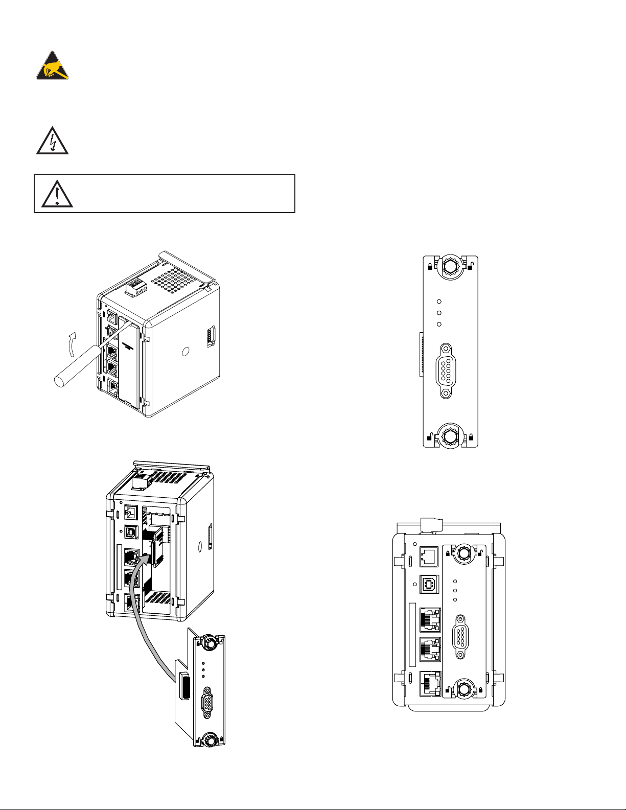
1. Remove power from the unit
2. Insert a flat-bladed screwdriver into the slot at the top of the expansion port
cover. Gently apply pressure on the screwdriver in an upward direction until
the expansion port cover disengages from the unit as shown in Figure 1.
3. Verify that the option card knobs are in the “unlocked” position as shown in
Figure 2.
4. Carefully insert the option card into the expansion port opening while
aligning the card-edge connector on the option card with the main board’s
header, as shown in Figure 3. Once aligned, gently press on the front of the
card until it is flush with the front of the case.
5. Turn the option card knobs to the locked position as shown in Figure 4.
DP
WD
DATA
Figure 1
DP
WD
DATA
Figure 2
DP
WD
DATA
Figure 3
Figure 4
2
Page 3

POWER SUPPLY REQUIREMENTS
NEW AND EXISTING INSTALLATIONS
The VFG9000-PBDP option card draws all of its power from the main board
of the Fieldbus Gateway. The specifications of the Fieldbus Gateway account
for the power needs of an option card.
WARNING - EXPLOSION HAZARD - DO NOT DISCONNECT
WHILE CIRCUIT IS ALIVE UNLESS AREA IS KNOW TO BE
NON-HAZARDOUS.
COMMUNICATING WITH THE VFG9000-PBDP
OPTION CARD
CONFIGURING THE VFG9000-PBDP OPTION CARD
The VFG9000-PBDP is configured using Fieldbus Gateway Manager software.
Updates to the software for new features and drivers are posted on the website
as they become available. By configuring the VFG9000-PBDP using the latest
version of the software, you are assured that your unit has the most up-to-date
feature set. Additional information can be found in your hardware bulletin and
also in the Fieldbus Gateway Manager user manual.
To enable the option card, click on the left hand pane of the Communications
window in Fieldbus Gateway Manager and highlight the icon that represents the
Fieldbus Gateway. In the right pane, click the Option Card Selection’s Edit
button to show the selection dialog, and choose the PROFIBUS option card
from the list. The PROFIBUS option card will then appear in the left hand pane,
installed in the tree of available ports.
CONFIGURING THE DRIVER
To select a driver, click on the left hand pane of the Communications window
and highlight the PROFIBUS Interface icon. In the right hand pane, click the
Driver Selection Edit button to show the Driver Selection dialog and select the
PROFIBUS DP driver from the list.
The Station Address of the PROFIBUS node is the only property that needs
to be configured. This should be a unique address on the PROFIBUS Network
in the range 1..125.
SOFTWARE/UNIT OPERATION
LEDS
The card has 3 LEDs visible on the front of the option card that provide status
information, described in Table 1.
DATA (Red) WD (Green) DP (Red) DESCRIPTION
OFF Baud Search
OFF OFF ON Baud Control
OFF SLOW FLASH FAST FLASH
OFF FAST FLASH SLOW FLASH
ON OFF OFF Data Exchange
TROUBLESHOOTING YOUR VFG9000-PBDP OPTION CARD
If for any reason you have trouble operating, connecting, or simply have
questions concerning your new VFG9000-PBDP option card, contact B&B
Electronics’ technical support. For contact information, refer to the back page
of this bulletin for phone and fax numbers.
Web Site: http://www.bb-elec.com
SLOW ALTERNATING FLASH
Waiting for Parameter Telegram
Waiting for Configuration Telegram
CONFIGURING THE DATA TAGS
A PROFIBUS master exchanges data with slaves as separate input and output
blocks. Data transfer direction is described with respect to the PROFIBUS
Network such that input data is transferred to the network, or written by the
Fieldbus Gateway and output data is transferred from the network or read by the
Fieldbus Gateway. This is important when it comes to configuring the data
access for each tag mapped to a PROFIBUS data block.
MAPPING TAGS TO PROFIBUS
PROFIBUS data blocks have no concept or knowledge of data type or
structure – they are described by a size in bytes. Fieldbus Gateway Manager’s
tag-based approach to data allows for data of mixed type, bytes, 16-bit words,
32-bit words and 32-bit floating point numbers to be mapped into a single data
block. To map a data tag to a PROFIBUS data block, click in the left hand pane
of the Data Tags window, highlight the required Data Tag icon. In the right hand
pane click the Data Mapping button and select the PROFIBUS device to show
the Select Address for PROFIBUS DP dialog.
The Block Type defines whether the tag will be read from (Output Block) or
written to (Input Block) the PROFIBUS network
The Data Offset is the byte address of the Data Tag within the Data Block
The Data Type is the actual size in bytes of the data that will be mapped into
the Data Block.
CONFIGURING DATA ACCESS IN
As described, Data Tags are mapped to either an Input Block
and are Write only, or an Output Block and are Read Only. The
Access must be selected to reflect this.
FIELDBUS GATEWAY MANAGER
3
Page 4

 Loading...