

Page 1
Phone: (815) 433-5100
Fax: (815) 4334-5104
www.bb-elec.com
10/100 ETHERNET OPTION CARD FOR VLINX ConnectPro
CONFIGURED USING Vlinx ConnectPro MANAGER 2.0
10 BASE-T/100 BASE-TX ETHERNET PORT
EASY INSTALLATION
NOTICE
This product does not have a UL rating. Installing Non-UL Rated parts
or components into any UL Rated device voids the original UL rating on
that device.
VFG9000-ENET-0911qsg
GENERAL DESCRIPTION
The Vlinx ConnectPro contains a proprietary expansion port which provides
a high speed, parallel architecture that extends the functionality and flexibility
of the platform. This approach allows these products to evolve concurrently
with the latest advances in communications and standards, without sacrificing
performance. This high bandwidth channel has significantly greater throughput
when compared to the traditional (external) serial gateway approach.
The auxiliary Ethernet port provides a means to isolate machine-network
traffic from the plant-wide network, thereby negating the need for an industrial
router. Further, by isolating the machine and plant-wide networks, the system
only requires that a single IP address be provided by the company’s IT group.
The VFG9000-ENET option card is easily installed by removing the blank
expansion port cover of your Vlinx ConnectPro, and plugging the VFG9000ENET card into the expansion port. Installing this card adds an auxiliary 10/100
Ethernet port to any Vlinx ConnectPro. Configuration is simple using B&B
Electronics’ free Vlinx ConnectPro Manager 2.0 software.
SAFETY SUMMARY
All safety related regulations, local codes and instructions that appear in the
literature or on equipment must be observed to ensure personal safety and to
prevent damage to either the instrument or equipment connected to it. If
equipment is used in a manner not specified by the manufacturer, the protection
provided by the equipment may be impaired.
Do not use the controller to directly command motors, valves, or other
actuators not equipped with safeguards. To do so can be potentially harmful to
persons or equipment in the event of a fault to the controller.
CAUTION: Risk of Danger.
Read complete instructions prior to
installation and operation of the unit.
SPECIFICATIONS
1. POWER REQUIREMENTS: 24 V @ 30 mA max. Power is supplied to the
option card by the Vlinx ConnectPro.
2. COMMUNICATIONS:
Ethernet Port: 10 BASE-T / 100 BASE-TX
RJ45 jack is wired as a NIC (Network Interface Card).
3. CERTIFICATIONS AND COMPLIANCES:
Consult factory for details.
ELECTROMAGNETIC COMPATIBILITY
Emissions and Immunity to EN 61326: Electrical Equipment for Measurement,
Control and Laboratory use.
Reference Vlinx ConnectPro unit for EMC specifications
4. ENVIRONMENTAL CONDITIONS:
Refer to the specifications of the Vlinx ConnectPro you are installing this
card in.
5. CONSTRUCTION: For indoor use only. Installation Category II, Pollution
Degree 2.
6. INSTALLATION REQUIREMENTS: See “Installing the VFG9000-
ENET Option card” for more details.
7. WEIGHT: 2.0 oz (56.7 g)
ORDERING INFORMATION
DESCRIPTION PART NUMBER
Ethernet option card for Vlinx ConnectPro VFG9000-ENET00
CONTENTS OF PACKAGE
- VFG9000-ENET option card
- This hardware bulletin
LP0866
Effective 03/11
1
Page 2
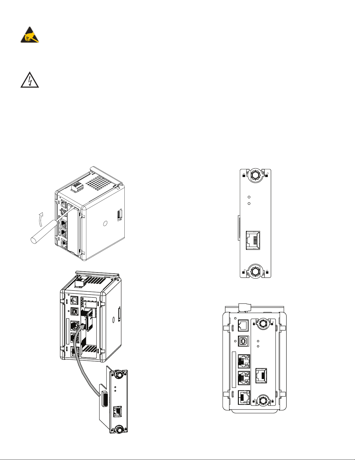
INSTALLING THE VFG9000-ENET OPTION CARD
Caution: The expansion and main circuit boards contain static
sensitive components. Before handling the cards, discharge static
charges from your body by touching a grounded bare metal object.
Ideally, handle the cards at a static controlled clean workstation.
Also, handle the cards by the edges only. Dirt, oil, or other
contaminants that may contact the cards can adversely affect circuit
operation.
Warning: Risk of Danger: Be sure to remove all power before
removing the expansion port cover
1. Remove power from the unit
2. Insert a flat-bladed screwdriver into the slot at the top of the expansion port
cover. Gently apply pressure on the screwdriver in an upward direction until
the expansion port cover disengages from the unit as shown in Figure 1.
3. Verify that the option card knobs are in the “unlocked” position as shown in
Figure 2.
4. Carefully insert the option card into the expansion port opening while
aligning the card-edge connector on the option card with the main board's
header, as shown in Figure 3. Once aligned, gently press on the front of the
card until it is flush with the front of the case.
5. Turn the option card knobs to the locked position as shown in Figure 4.
Figure 1
LINK
Tx/Rx
Figure 2
LINK
Tx/Rx
Figure 3
LINK
Tx/Rx
Figure 4
2
Page 3

THE OPTION CARD LABEL
Place the option card label on the outer plastic cover of the Vlinx ConnectPro.
The label contains the MAC ID of the particular VFG9000-ENET option card
being used.
POWER SUPPLY REQUIREMENTS
NEW AND EXISTING INSTALLATIONS
The VFG9000-ENET option card draws all of its power from the main board
of the Vlinx ConnectPro. The specifications of the Vlinx ConnectPro account
for the power needs of an option card.
SOFTWARE/UNIT OPERATION
LEDS
The Link and Tx/Rx LEDs, shown in Figure 2, indicate the status of the
Ethernet port. Refer to the following chart.
LED COLOR DESCRIPTION
GREEN 10 BASE-T Communications
LINK
AMBER 100 BASE-TX Communications
YELLOW solid Link established
Rx/Tx
YELLOW flashing Data being transferred
COMMUNICATING WITH THE VFG9000-ENET
OPTION CARD
CONFIGURING THE VFG9000-ENET OPTION CARD
The VFG9000-ENET is configured using Vlinx ConnectPro Manager 2.0
software. Updates to Vlinx ConnectPro Manager 2.0 for new features and drivers
are posted on the website as they become available. By configuring the VFG9000ENET using the latest version of Vlinx ConnectPro Manager 2.0, you are assured
that your unit has the most up-to-date feature set. Additional information can be
found in your hardware bulletin and also in the Vlinx ConnectPro Manager 2.0
user manual.
ETHERNET COMMUNICATIONS
Ethernet communications can be established at either 10 BASE-T or 100
BASE-TX. The VFG9000-ENET option card’s RJ45 jack is wired as a NIC
(Network Interface Card). VFG9000-ENET option card auto-detects remote
transmit and receive pairs and correctly assigns the transmit and receive pairs
for the VFG9000-ENET option card. This exteremly useful feature enables the
user to use whichever type of cable (cross-over or straight) is available.
TROUBLESHOOTING YOUR VFG9000-ENET OPTION CARD
If for any reason you have trouble operating, connecting, or simply have
questions concerning your new VFG9000-ENET option card, contact B&B
Electronics’ technical support. For contact information, refer to the back page
of this bulletin for phone and fax numbers.
Web Site: http://www.bb-elec.com
3
Page 4

B&B Electronics
International Headquarters
707 Dayton Road
P.O. Box 1040
Ottawa, IL 61350
Phone: (815) 433-5100
Fax: (815) 433-5104
B&B Electronics Ltd
European Headquarters
Westlink Commercial Park,
Oranmore, Co. Galway, Ireland
Phone: +353 91 792444
Fax:+353 91 792445
 Loading...