

Page 1
Phone: (815) 433-5100
Fax: (815) 4334-5104
www.bb-elec.com
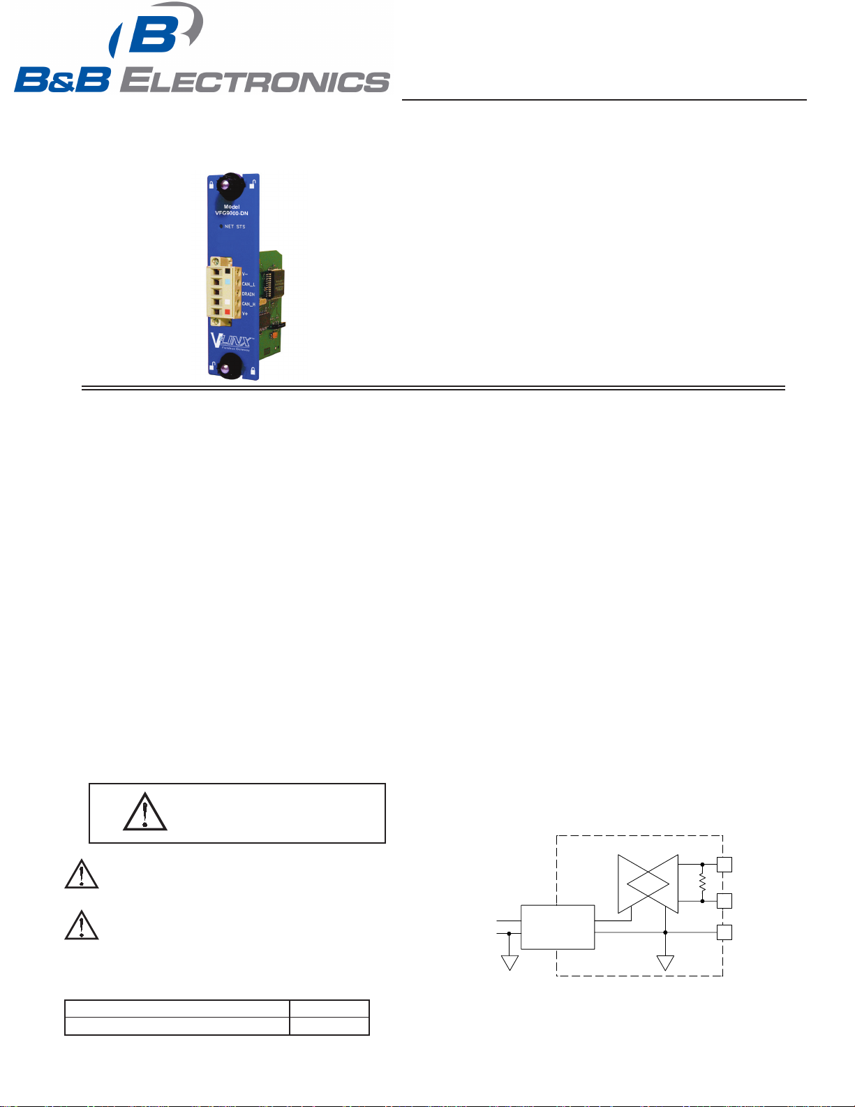
DeviceNet OPTION CARD FOR VLINX FIELDBUS GATEWAY
CONFIGURED USING VLINX FIELDBUS GATEWAY MANAGER
DIGITALLY ISOLATED DeviceNet PORT CAPABLE OF
COMMUNICATING WITH ANY DeviceNet MASTER
EASY INSTALLATION
VFG9000-DN-qsg
GENERAL DESCRIPTION
The Vlinx Fieldbus Gateway contains a proprietary expansion port which
provides a high speed, parallel architecture that extends the functionality and
flexibility of the platform. This approach allows these products to evolve
concurrently with the latest advances in communications and standards, without
sacrificing performance. This high bandwidth channel has significantly greater
throughput when compared to the traditional (external) serial gateway approach.
The VFG9000-DN option card adds a DeviceNet slave communication port
to the series. This isolated card protects user equipment from potentially
harmful ground loops while providing the ability to communicate to any high
speed DeviceNet master. Additionally, the VFG9000-DN connector is pluggable
for easy removal of the Fieldbus Gateway from the DeviceNet bus without
disturbing communications with other devices on the bus.
The VFG9000-DN communication card is easily installed by removing the
blank expansion port cover of your Fieldbus Gateway, and plugging the
VFG9000-DN card into the expansion port. Configuration is simple using B&B
Electronics’ free Fieldbus Gateway Manager software.
SAFETY SUMMARY
All safety related regulations, local codes and instructions that appear in the
literature or on equipment must be observed to ensure personal safety and to
prevent damage to either the instrument or equipment connected to it. If
equipment is used in a manner not specified by the manufacturer, the protection
provided by the equipment may be impaired.
Do not use the controller to directly command motors, valves, or other
actuators not equipped with safeguards. To do so can be potentially harmful to
persons or equipment in the event of a fault to the controller.
CAUTION: Risk of Danger.
Read complete instructions prior to
installation and operation of the unit.
CONTENTS OF PACKAGE
- VFG9000-DN option card
- This hardware bulletin
SPECIFICATIONS
1. POWER REQUIREMENTS: 24 V @ 50 mA max. Power is supplied to the
option card from the main board of the Fieldbus Gateway.
2. COMMUNICATIONS:
DeviceNet Port: The DeviceNet port has format and baud rates that are
software programmable up to 500K baud and are digitally isolated. This port
may be configured for various DeviceNet protocols. Check www.bb-elec.com
for currently supported protocols.
Isolation from VFG9000-DN Communication ports Fieldbus Gateway:
1000 VDC for 1 minute.
3. CERTIFICATIONS AND COMPLIANCES:
Refer to main unit manual or “Agency Approvals” section of B&B
Electronics’ website for agency certifications.
ELECTROMAGNETIC COMPATIBILITY
Emissions and Immunity to EN 61326: Electrical Equipment for Measurement,
Control and Laboratory use.
Reference Fieldbus Gateway unit for EMC specifications
4. ENVIRONMENTAL CONDITIONS:
Refer to the specifications of the Fieldbus Gateway you are installing this
card in.
5. CONSTRUCTION: For indoor use only. Installation Category II, Pollution
Degree 2.
6. INSTALLATION REQUIREMENTS: See “Installing the VFG9000-DN
Option card” for more details.
7. WEIGHT: 2.3 oz (65.2 g)
BLOCK DIAGRAM
WARNING - EXPLOSION HAZARD - SUBSTITUTION OF
COMPONENTS MAY IMPAIR SUITABILITY FOR CLASS I,
DIVISION 2
THIS EQUIPMENT IS SUITABLE FOR USE IN CLASS I,
DIVISION 2, GROUPS A, B, C, D, OR NON-HAZARDOUS
LOCATIONS ONLY
ORDERING INFORMATION
DESCRIPTION PART NUMBER
DeviceNet option card for Fieldbus Gateway VFG9000-DN
4 CAN_H
TX/RX
2
CAN_L
+
-
A
ISOLATING
DC : DC
1
V -
B
LP0835X
Effective 01/10
1
Page 2
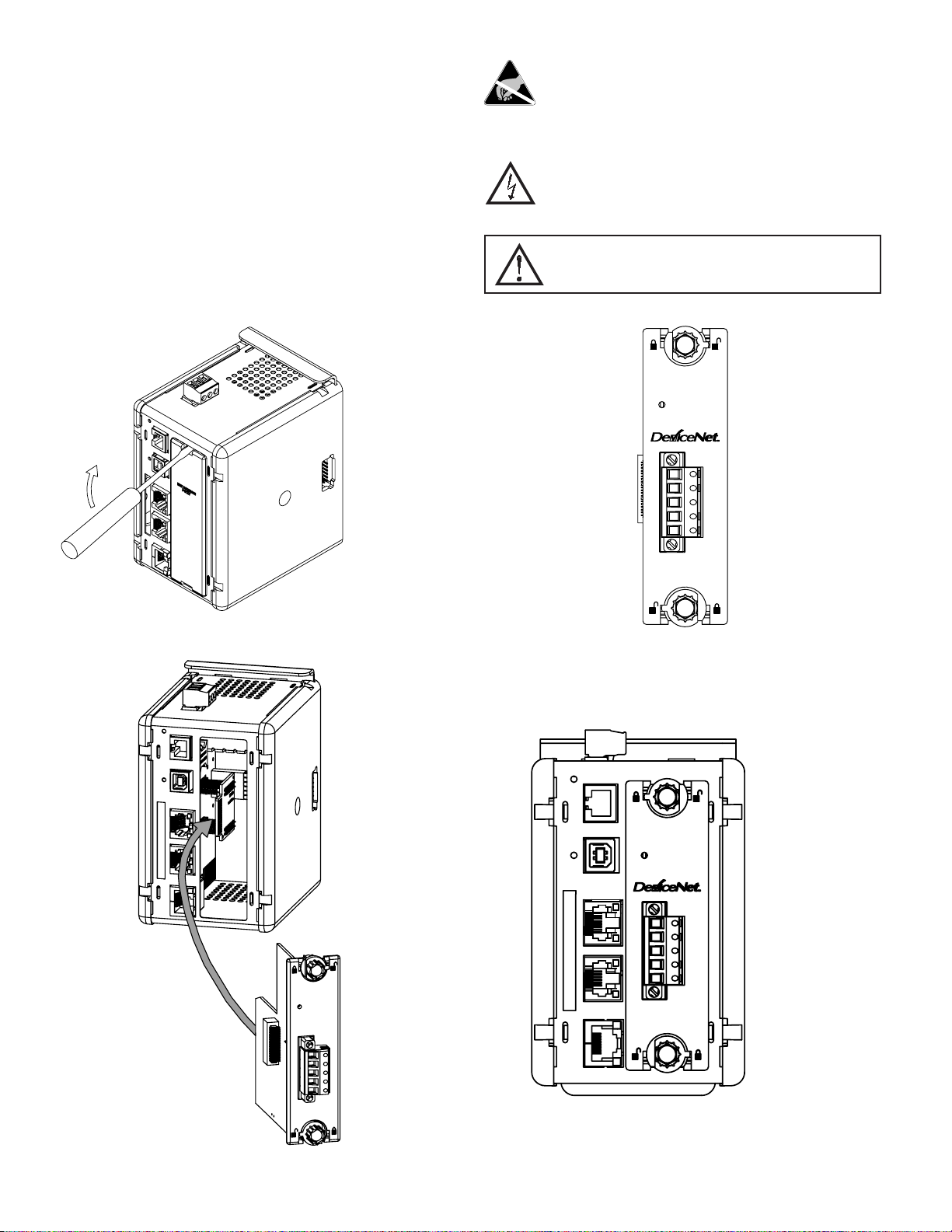
INSTALLING THE VFG9000-DN OPTION CARD
1. Remove power from the unit
2. Insert a flat-bladed screwdriver into the slot at the top of the expansion port
cover. Gently apply pressure on the screwdriver in an upward direction until
the expansion port cover disengages from the unit as shown in Figure 1.
3. Verify that the option card knobs are in the "unlocked" position as shown in
Figure 2.
4. Carefully insert the option card into the expansion port opening while
aligning the card-edge connector on the option card with the main board's
header, as shown in Figure 3. Once aligned, gently press on the front of the
card until it is flush with the front of the case.
5. Turn the option card knobs to the locked position as shown in Figure 4.
Caution: The expansion and main circuit boards contain static
sensitive components. Before handling the cards, discharge static
charges from your body by touching a grounded bare metal object.
Ideally, handle the cards at a static controlled clean workstation.
Also, handle the cards by the edges only. Dirt, oil, or other
contaminants that may contact the cards can adversely affect circuit
operation.
Warning: Risk of Danger: Be sure to remove all power before
removing the expansion port cover
WARNING - EXPLOSION HAZARD - DO NOT DISCONNECT
EQUIPMENT UNLESS POWER HAS BEEN SWITCHED OFF OR
AREA IS KNOWN TO BE NON-HAZARDOUS.
NET STS
Figure 1
Figure 2
V-
CAN_L
DRAIN
CAN_H
V+
NET STS
Figure 3
NET STS
V-
CAN_L
DRAIN
CAN_H
V+
Figure 4
2
Page 3

POWER SUPPLY REQUIREMENTS
NEW AND EXISTING INSTALLATIONS
The VFG9000-DN option card draws all of its power from the main board of
the Fieldbus Gateway. The specifications of the Fieldbus Gateway account for
the power needs of an option card.
WARNING - EXPLOSION HAZARD - DO NOT DISCONNECT
WHILE CIRCUIT IS ALIVE UNLESS AREA IS KNOW TO BE
NON-HAZARDOUS.
COMMUNICATING WITH THE VFG9000-DN OPTION
CARD
CONFIGURING A VFG9000-DN OPTION CARD
The VFG9000-DN is configured using Fieldbus Gateway Manager software.
Updates to the software for new features and drivers are posted on the website
as they become available. By configuring the VFG9000-DN using the latest
version of the software, you are assured that your unit has the most up-to-date
feature set. Fieldbus Gateway Manager software can configure the VFG9000DN through the RS232 PGM port, USB port, Ethernet port, or CompactFlash
socket on your Fieldbus Gateway. Additional information can be found in your
Fieldbus Gateway hardware bulletin and the Fieldbus Gateway Manager user
manual.
DeviceNet PORT PROTOCOLS
The VFG9000-DN option card has one DeviceNet port. This port may be
configured for various DeviceNet protocols. Check www.bb-elec.com for
currently supported protocols.
SOFTWARE/UNIT OPERATIONS
LED
LED STATE
OFF Initializing
FLASHING GREEN
GREEN
FLASHING RED One or more established communications have timed out
RED
The device is online and is waiting on communications
from other devices
The device is online and has established
communications with another device
The device has detected an error that has rendered it
incapable of communicating on the network (duplicate
MAC ID or bus activity).
VFG9000-DN CARD INDICATION
TROUBLESHOOTING YOUR VFG9000-DN OPTION
CARD
If for any reason you have trouble operating, connecting, or simply have
questions concerning your new VFG9000-DN option card, contact B&B
Electronics’ technical support. For contact information, refer to the back page of
this bulletin for phone and fax numbers.
Web Site: http://www.bb-elec.com
VFG9000-DN PORT PIN OUTS
Must use only NEC Class 2 or Limited Power Source (LPS) rated power
supply.
V-
LED
DRAIN
CAN_L
V-
Position 1 of the pluggable connector provides a CAN ground connection.
This terminal is isolated from the Fieldbus Gateway.
CAN_L
Position 2 of the pluggable connector provides the CAN_L bus line (active
low). This terminal is isolated from the Fieldbus Gateway.
DRAIN (OPTIONAL)
Position 3 of the pluggable connector is provided for optional drain
connections. This position is available only to tie drain wires together or to earth
ground. There is no internal connection to earth ground. The DRAIN position is
not connected to any circuitry internal to the VFG9000-DN option card or
Fieldbus Gateway.
CAN_H
Position 4 of the pluggable connector provides the CAN_H bus line (active
high). This terminal is isolated from the Fieldbus Gateway.
V+
CAN_H
V+ (OPTIONAL 24 VDC)
Position 5 of the pluggable connector is provided for optional 24 VDC
connections. This position is available only to tie 24 VDC wires together. The
VFG9000-DN card neither provides 24 VDC power nor uses 24 VDC power
through this connection. The V+ position is not connected to any circuitry
internal to the VFG9000-DN option card or Fieldbus Gateway.
3
Page 4

 Loading...