

Page 1
VFG9000-CEL-1012qsg
Phone: (815) 433-5100
Fax: (815) 4334-5104
www.bb-elec.com
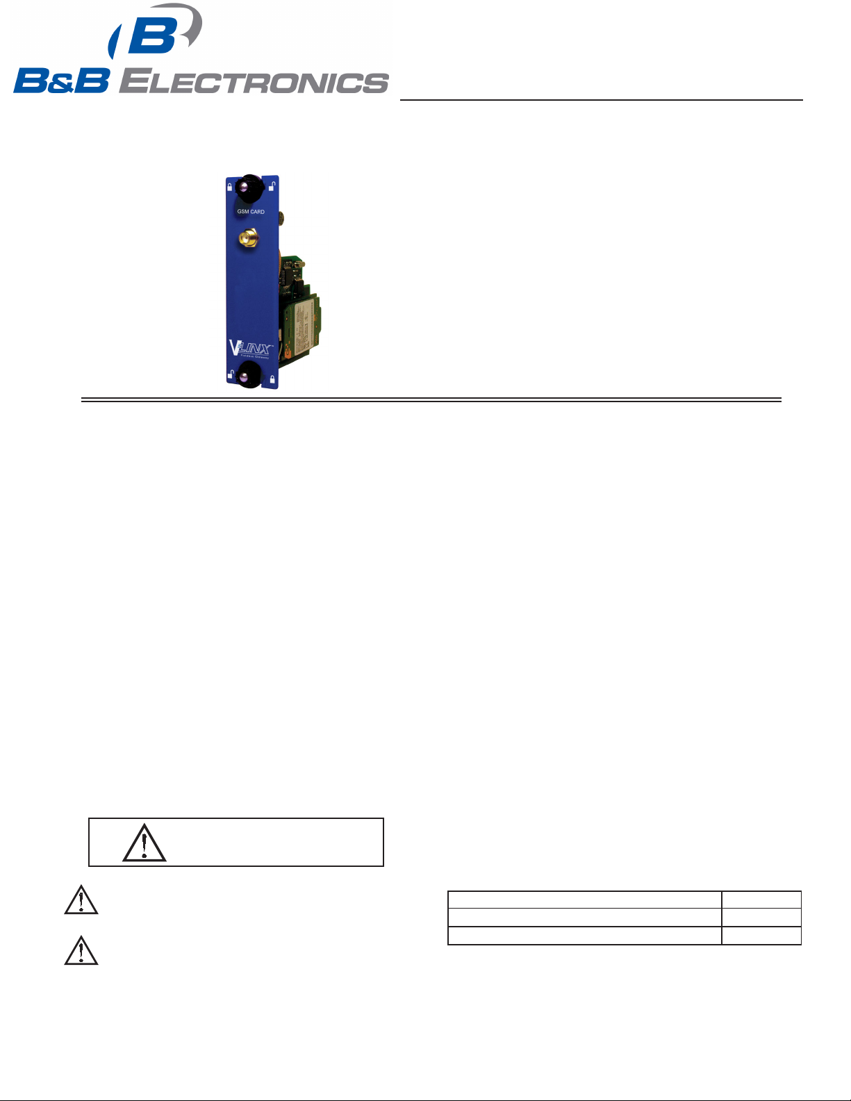
GSM/GPRS CELLULAR MODEM OPTION CARD FOR VLINX FIELDBUS
GATEWAY
CONFIGURED USING VLINX FIELDBUS GATEWAY MANAGER
INSTALLS INSIDE A FIELDBUS GATEWAY
INSTALLATION AND CONNECTION HARDWARE ARE INCLUDED
WITH CARD
GENERAL DESCRIPTION
The VFG9000-CEL option card allows the user to add GSM/GPRS cellular
modem capability to their Fieldbus Gateway. GSM/GPRS is the most prevalent
cellular technology in today’s markets. GPRS can be used for services such as
Wireless Application Protocol (WAP) access, Short Message Service (SMS),
and for Internet communication services such as email and World Wide Web
access. The VFG9000-CEL modem option card is quad-band, allowing it to
work in frequencies across the Americas, Europe and Asia. US and Canada
work in the 850/1900 MHz bands, while Europe, Middle East, Africa and most
of Asia work in the 900/1800 MHz GSM/GPRS frequencies.
The VFG9000-CEL requires the addition of a SIM (Subscriber Identity
Module) card, which is inserted into the holder prior to installation of the
VFG9000-CEL card. The SIM card securely stores the service-subscriber key
(IMSI) used to identify a subscriber, and is used to connect to the network to
obtain an IP address from the provider.
The VFG9000-CEL communication card is easily installed by removing the
blank expansion port cover of your Fieldbus Gateway, and plugging the
VFG9000-CEL card into the expansion port. Configuration is simple using
B&B Electronics’ free Fieldbus Gateway Manager software.
SAFETY SUMMARY
All safety related regulations, local codes and instructions that appear in the
literature or on equipment must be observed to ensure personal safety and to
prevent damage to either the instrument or equipment connected to it. If
equipment is used in a manner not specified by the manufacturer, the protection
provided by the equipment may be impaired.
Do not use the controller to directly command motors, valves, or other
actuators not equipped with safeguards. To do so can be potentially harmful to
persons or equipment in the event of a fault to the controller.
CAUTION: Risk of Danger.
Read complete instructions prior to
installation and operation of the unit.
SPECIFICATIONS
1. POWER REQUIREMENTS: 24 V @ 125 mA max. Power is supplied to
the option card from the main board of the Fieldbus Gateway.
2. ANTENNA CONNECTOR:
SMA Female connector requires:
50 Ohm antenna with SMA male connector
Quad-band antenna (850/900/1800/1900 MHz) for global support.
Dual-band (850/1900 MHz) antenna for US and Canada only
Dual band (900/1800 MHz) for Europe only
The antenna cable should be 50 Ω impedance, RG178/U or RG174/U type
and be able to connect to the RSMA (Male) jack bulkhead. The antenna
could be horizontal, vertical or right angled. Longer antenna cable would
equate to signal loss.
This device is intended for connection to an antenna mounted within the
building or a UL certified enclosure suitably rated for application.
3. CERTIFICATIONS AND COMPLIANCES:
Refer to main unit manual or “Agency Approvals” section of B&B
Electronics’ website for agency certifications.
ELECTROMAGNETIC COMPATIBILITY
Emissions and Immunity to EN 61326: Electrical Equipment for
Measurement, Control and Laboratory use.
Reference Fieldbus Gateway unit for EMC specifications
The VFG9000-CEL option card has been tested and found to comply with the
limits for a Class A digital device, pursuant to part 15 of the FCC rules.
4. ENVIRONMENTAL CONDITIONS:
Refer to the specifications of the Fieldbus Gateway you are installing this
card in.
5. CONSTRUCTION: For indoor use only. Installation Category II, Pollution
Degree 2.
6. INSTALLATION REQUIREMENTS: See “Installing the VFG9000-CEL
Option card” for more details.
7. WEIGHT: 3.2 oz (94.64g)
WARNING - EXPLOSION HAZARD - SUBSTITUTION OF
COMPONENTS MAY IMPAIR SUITABILITY FOR CLASS I,
DIVISION 2
THIS EQUIPMENT IS SUITABLE FOR USE IN CLASS I,
DIVISION 2, GROUPS A, B, C, D, OR NON-HAZARDOUS
LOCATIONS ONLY
CONTENTS OF PACKAGE
- VFG9000-CEL option card
- This hardware bulletin
ORDERING INFORMATION
DESCRIPTION PART NUMBER
GSM/GPRS Cell Modem Option Card for Fieldbus Gateway VFG9000-CEL
Quad band GSM/GPRS Cellular antenna
1
QANT00 is a 6 inch direct mount Quad-band antenna.
1
1
LP0836X
Effective 01/10
QANT00
Page 2
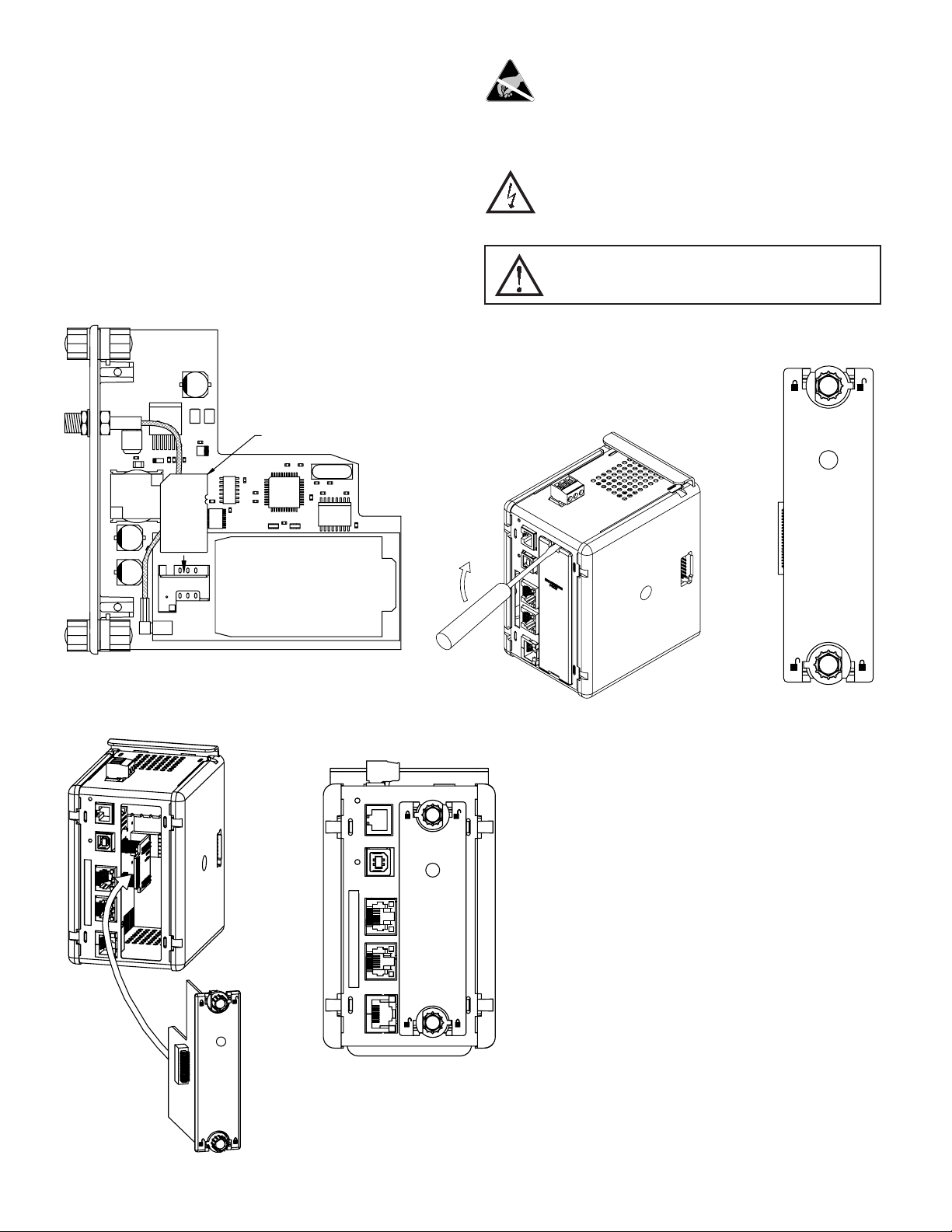
INSTALLING THE VFG9000-CEL OPTION CARD
The first step is to buy a SIM Card from one of the GSM/GPRS providers and
insert it into the SIM Card slot of the option card. The SIM Card slot is the
rectangular slot on top of the GSM/GPRS Cellular Modem in the VFG9000CEL option card as shown in Figure 1. See SIM Card details in the Software/
Unit Operation Section for more details.
1. Remove power from the unit.
2. Insert a flat-bladed screwdriver into the slot at the top of the expansion port
cover. Gently apply pressure on the screwdriver in an upward direction until
the expansion port cover disengages from the unit as shown in Figure 2.
3. Verify that the option card knobs are in the “unlocked” position as shown in
Figure 3.
4. Carefully insert the option card into the expansion port opening while
aligning the card-edge connector on the option card with the main board's
header, as shown in Figure 4. Once aligned, gently press on the front of the
card until it is flush with the front of the case.
5. Turn the option card knobs to the locked position as shown in Figure 5.
6,0&$5'
Caution: The expansion and main circuit boards contain static
sensitive components. Before handling the cards, discharge static
charges from your body by touching a grounded bare metal object.
Ideally, handle the cards at a static controlled clean workstation.
Also, handle the cards by the edges only. Dirt, oil, or other
contaminants that may contact the cards can adversely affect circuit
operation.
Warning: Risk of Danger: Be sure to remove all power before
removing the expansion port cover.
WARNING - EXPLOSION HAZARD - DO NOT DISCONNECT
EQUIPMENT UNLESS POWER HAS BEEN SWITCHED OFF OR
AREA IS KNOWN TO BE NON-HAZARDOUS.
Figure 1
*60*356&(//02'(0
Figure 2
Figure 3
THE OPTION CARD LABEL
Place the option card label on your outer plastic cover of the
Fieldbus Gateway. The label displays the FCC ID of the particular
modem being used in the VFG9000-CEL card.
Figure 4
Figure 5
2
Page 3

POWER SUPPLY REQUIREMENTS
NEW AND EXISTING INSTALLATIONS
The VFG9000-CEL option card draws all of its power from the main board
of the Fieldbus Gateway. The specifications of the Fieldbus Gateway account
for the power needs of an option card.
SOFTWARE / UNIT OPERATION
WARNING - EXPLOSION HAZARD - DO NOT DISCONNECT
WHILE CIRCUIT IS ALIVE UNLESS AREA IS KNOW TO BE
NON-HAZARDOUS.
CONFIGURING A VFG9000-CEL OPTION CARD
The VFG9000-CEL is configured using Fieldbus Gateway Manager software.
Updates to the software for new features and drivers are posted on the website
as they become available. By configuring the VFG9000-CEL using the latest
version of the software, you are assured that your unit has the most up to date
feature set. Fieldbus Gateway Manager software can configure the VFG9000CEL through the option card selection. After choosing the Cellular Modem
option card, it is set up as a PPP Modem client, PPP Modem server or SMS via
GSM Modem.
All VFG9000-CEL option cards are configured to US GSM/GPRS frequency
band (850/1900 MHz) by default. During setup of the Cellular Modem Option
card, the appropriate GSM/GPRS frequency band must be chosen depending on
the geographical location of the Fieldbus Gateway. Once the option card is
configured through Fieldbus Gateway Manager software, it needs to be
downloaded to the Fieldbus Gateway. The Fieldbus Gateway with the
VFG9000-CEL option card needs to be power cycled for the configuration
changes with respect to the GSM/GPRS frequency band to take effect.
Additional information can be found in your Fieldbus Gateway hardware
bulletin and the Fieldbus Gateway Manager user manual.
SIM CARD INSTALLATION & DETAILS
A SIM Card has to be installed on the VFG9000-CEL option card before
installing the option card in the Fieldbus Gateway.
TROUBLESHOOTING YOUR VFG9000-CEL
OPTION CARD
If for any reason you have trouble operating, connecting, or simply have
questions concerning your new VFG9000-CEL option card, contact B&B
Electronics’ technical support. For contact information, refer to the back page
of this bulletin for phone and fax numbers.
Web Site: http://www.bb-elec.com
3
Page 4

 Loading...