

Page 1

REV 1
FIELDBUS
GATEWAY
MANAGER
USER MANUAL
Phone: (815) 433-5100
Fax: (815) 4334-5104
www.bb-elec.com
VFG1000/2000/3000-0310M
Page 2

Copyright © 2010 B&B Electronics.
All Rights Reserved Worldwide.
The information contained herein is provided in good faith, but is subject to change without
notice. It is supplied with no warranty whatsoever, and does not represent a commitment on
the part of B&B Electronics. Companies, names and data used as examples herein are
fictitious unless otherwise stated. No part of this document may be reproduced or transmitted
in any form or by any means, electronic or mechanical, without the express written
permission of B&B Electronics
All trademarks are acknowledged as the property of their respective owners.
Page 3

TABLE OF CONTENTS
TABLE OF CONTENTS
GETTING STARTED ..........................................................................................1
SYSTEM REQUIREMENTS .................................................................................... 1
INSTALLING THE SOFTWARE ............................................................................... 1
CHECKING FOR UPDATES ................................................................................... 1
INSTALLING THE USB DRIVERS ........................................................................... 2
FIELDBUS GATEWAY MANAGER BASICS ...............................................................3
MAIN SCREEN ICONS ........................................................................................ 3
COMMUNICATIONS ............................................................................................................................ 3
DATA TAGS ..................................................................................................................................... 3
USER INTERFACE .............................................................................................................................. 4
PROGRAMMING ................................................................................................................................ 4
DATA LOGGER ................................................................................................................................. 4
WEB SERVER ................................................................................................................................... 4
SECURITY MANAGER ......................................................................................................................... 5
SELECTING A MODEL ........................................................................................ 5
USING BALLOON HELP ...................................................................................... 5
WORKING WITH DATABASES............................................................................... 6
DOWNLOADING TO A VLINX FIELDBUS GATEWAY ...................................................... 6
CONFIGURING THE LINK ..................................................................................................................... 6
VERIFYING THE USB LINK .................................................................................................................. 7
SETTING THE IP ADDRESS .................................................................................................................. 7
SENDING THE DATABASE .................................................................................................................... 7
EXTRACTING DATABASES .................................................................................................................... 8
MOUNTING THE COMPACTFLASH .......................................................................................................... 8
FORMATTING THE COMPACTFLASH ........................................................................................................ 9
SENDING THE TIME AND DATE ............................................................................................................. 9
UPDATING VIA COMPACTFLASH ..........................................................................10
GURU MEDITATION CODES ...............................................................................10
CONFIGURING COMMUNICATIONS .................................................................... 13
SERIAL PORT USAGE .......................................................................................13
SELECTING A PROTOCOL ..................................................................................13
PROTOCOL OPTIONS .......................................................................................14
WORKING WITH DEVICES .................................................................................14
ETHERNET CONFIGURATION ..............................................................................15
IP PARAMETERS ............................................................................................................................. 15
IP ROUTING .................................................................................................................................. 15
PHYSICAL LAYER ............................................................................................................................ 16
REMOTE UPDATE ............................................................................................................................ 16
PROTOCOL SELECTION ..................................................................................................................... 16
SLAVE PROTOCOLS .........................................................................................17
SELECTING THE PROTOCOL ............................................................................................................... 17
ADDING GATEWAY BLOCKS ............................................................................................................... 18
ADDING ITEMS TO A BLOCK .............................................................................................................. 19
ACCESSING INDIVIDUAL BITS ............................................................................................................ 19
REVISION 1 PAGE I
Page 4

TABLE OF CONTENTS VLINX FIELDBUS GATEWAY MANAGER USER MANUAL
PROTOCOL CONVERSION ................................................................................. 20
MASTER AND SLAVE ........................................................................................................................ 20
MASTER AND MASTER ...................................................................................................................... 20
WHICH WAY AROUND? .................................................................................................................... 21
DATA TRANSFORMATION ................................................................................. 21
ADVANCED COMMUNICATIONS ........................................................................ 23
USING EXPANSION CARDS ............................................................................... 23
SHARING SERIAL PORTS .................................................................................. 24
ENABLING TCP/IP .......................................................................................................................... 24
SHARING THE REQUIRED PORT .......................................................................................................... 24
CONNECTING VIA ANOTHER PORT ...................................................................................................... 24
CONNECTING VIA ETHERNET ............................................................................................................. 25
PURE VIRTUAL PORTS ..................................................................................................................... 26
LIMITATIONS ................................................................................................................................. 27
USING ELECTRONIC MAIL ................................................................................ 27
CONFIGURING SMTP ...................................................................................................................... 27
CONFIGURING SMS ........................................................................................................................ 29
THE ADDRESS BOOK ....................................................................................................................... 30
WORKING WITH MODEMS ................................................................................ 30
SOME TYPICAL APPLICATIONS ........................................................................................................... 31
ADDING A DIAL-IN CONNECTION ........................................................................................................ 32
ADDING A DIAL-OUT CONNECTION ..................................................................................................... 34
ADDING AN SMS CONNECTION .......................................................................................................... 35
SMS MESSAGE PROCESSING ............................................................................................................. 36
USING MULTIPLE INTERFACES ........................................................................................................... 36
CHECKING THE MODEM STATUS ......................................................................................................... 37
MODEM INITIALIZATION SEQUENCE .................................................................................................... 38
TROUBLESHOOTING MODEM COMMUNICATION ...................................................................................... 39
USING TIME MANAGEMENT .............................................................................. 40
CONFIGURING THE TIME MANAGER ..................................................................................................... 40
SELECTING AN SNTP SERVER ............................................................................................................ 42
TIME-ZONE CONFIGURATION ............................................................................................................ 43
CONFIGURING THE SYNCHRONIZATION MANAGER (FTP) .......................................... 43
SYNCHRONIZATION MANAGER SETTINGS .............................................................................................. 43
AUTOMATIC LOG SYNCHRONIZATION ................................................................................................... 44
ADVANCED FTP EXCHANGE FUNCTIONS ............................................................................................... 45
CONFIGURING THE FTP SERVER ........................................................................ 45
FTP SERVER SETTINGS .................................................................................................................... 46
FTP SECURITY............................................................................................................................... 46
ACCESSING THE SERVER ................................................................................................................... 47
CONFIGURING DATA TAGS .............................................................................. 49
ALL ABOUT TAGS .......................................................................................... 49
TYPES OF TAGS .............................................................................................................................. 49
TAGS? ......................................................................................................................................... 51
CREATING TAGS ............................................................................................ 52
EDITING TAGS .............................................................................................. 52
EDITING PROPERTIES ..................................................................................... 53
PAGE II
Page 5

TABLE OF CONTENTS
EXPRESSION PROPERTIES ................................................................................................................. 53
TRANSLATABLE STRINGS .................................................................................................................. 54
COLOR PROPERTIES ........................................................................................................................ 54
EDITING FLAG TAGS .......................................................................................55
THE DATA TAB (VARIABLES) ............................................................................................................. 55
THE DATA TAB (FORMULAE) ............................................................................................................. 57
THE DATA TAB (ARRAYS) ................................................................................................................. 57
THE FORMAT TAB ........................................................................................................................... 58
THE COLORS TAB ........................................................................................................................... 59
THE ALARMS TAB ........................................................................................................................... 60
THE TRIGGERS TAB ........................................................................................................................ 61
EDITING INTEGER TAGS ...................................................................................62
THE DATA TAB (VARIABLES) ............................................................................................................. 62
THE DATA TAB (FORMULAE) ............................................................................................................. 63
THE DATA TAB (ARRAYS) ................................................................................................................. 64
THE FORMAT TAB ........................................................................................................................... 65
THE COLORS TAB ........................................................................................................................... 66
THE ALARM TABS ........................................................................................................................... 67
THE TRIGGERS TAB ........................................................................................................................ 68
EDITING MULTI TAGS ......................................................................................68
THE DATA TAB (VARIABLES) ............................................................................................................. 69
THE DATA TAB (FORMULAE) ............................................................................................................. 69
THE DATA TAB (ARRAYS) ................................................................................................................. 70
THE FORMAT TAB ........................................................................................................................... 70
THE COLORS TAB ........................................................................................................................... 72
THE ALARM TABS ........................................................................................................................... 72
THE TRIGGERS TAB ........................................................................................................................ 73
EDITING REAL TAGS .......................................................................................73
EDITING STRING TAGS ....................................................................................73
THE DATA TAB (VARIABLES) ............................................................................................................. 74
THE DATA TAB (FORMULAE) ............................................................................................................. 75
THE DATA TAB (ARRAYS) ................................................................................................................. 75
THE FORMAT TAB ........................................................................................................................... 76
THE COLORS TAB ........................................................................................................................... 77
MORE THAN TWO ALARMS ................................................................................77
VALIDATING TAGS ..........................................................................................77
EXPORTING TAG MAPPINGS ...............................................................................78
LOGGING EVENT MESSAGES ..............................................................................78
CONFIGURING A VIRTUAL HMI ........................................................................ 79
CONTROLLING THE VIEW ..................................................................................79
ZOOM FUNCTION ............................................................................................................................ 79
OTHER VIEW OPTIONS .................................................................................................................... 80
USING THE PAGE LIST .....................................................................................80
WORKING WITH THE GRID ................................................................................81
THE DRAWING TOOLBOX ..................................................................................81
ADDING DISPLAY PRIMITIVES ............................................................................81
SMART ALIGNMENT ......................................................................................................................... 82
REVISION 1 PAGE III
Page 6

TABLE OF CONTENTS VLINX FIELDBUS GATEWAY MANAGER USER MANUAL
KEYBOARD OPTIONS ....................................................................................................................... 82
LOCK INSERT MODE ........................................................................................................................ 82
USING THE IMAGE LIBRARY .............................................................................. 83
SELECTING PRIMITIVES ................................................................................... 83
MOVING AND RESIZING ................................................................................... 83
ALIGNING PRIMITIVES .................................................................................... 84
SPACING PRIMITIVES ...................................................................................... 84
REORDERING PRIMITIVES ................................................................................ 85
GROUPING PRIMITIVES ................................................................................... 85
EDITING PRIMITIVES ...................................................................................... 85
DEFINING COLORS ......................................................................................... 86
DEFINING FILL PATTERNS ................................................................................ 87
DEFINING ACTIONS ........................................................................................ 87
ENABLING ACTIONS ....................................................................................... 87
ACTION DESCRIPTIONS ................................................................................... 88
THE GOTO PAGE ACTION ................................................................................................................. 88
THE PUSH BUTTON ACTION .............................................................................................................. 89
THE CHANGE INTEGER VALUE ACTION ................................................................................................. 90
THE RAMP INTEGER VALUE ACTION .................................................................................................... 90
THE USER DEFINED ACTION ............................................................................................................. 91
USING DEFAULT SETTINGS ............................................................................... 91
PRIMITIVE DESCRIPTIONS ................................................................................ 91
THE LINE PRIMITIVE ....................................................................................................................... 92
THE SIMPLE GEOMETRIC PRIMITIVES .................................................................................................. 92
THE TANK PRIMITIVES ..................................................................................................................... 92
THE SIMPLE BAR PRIMITIVES ............................................................................................................ 93
THE BAR-GRAPH PRIMITIVES ............................................................................................................ 93
THE SCATTER GRAPH PRIMITIVE ........................................................................................................ 94
THE SCALE PRIMITIVES .................................................................................................................... 97
THE FIXED TEXT PRIMITIVE .............................................................................................................. 98
THE AUTO TAG PRIMITIVE ................................................................................................................ 99
THE TAG TEXT PRIMITIVES ............................................................................................................. 100
EDITING THE UNDERLYING TAG ....................................................................................................... 104
THE MULTI-LINE TEXT PRIMITIVES ................................................................................................... 104
THE TIME AND DATE PRIMITIVE ....................................................................................................... 104
THE RICH BAR PRIMITIVES ............................................................................................................. 107
THE RICH SLIDER PRIMITIVES ......................................................................................................... 109
THE ALARM VIEWER PRIMITIVE ....................................................................................................... 111
THE ALARM TICKER PRIMITIVE ........................................................................................................ 116
THE EVENT VIEWER PRIMITIVE ........................................................................................................ 118
THE FILE VIEWER PRIMITIVE ........................................................................................................... 118
THE TRENDING PRIMITIVES ............................................................................................................ 119
THE GENERAL BUTTON PRIMITIVE .................................................................................................... 123
THE RICH BUTTON PRIMITIVE ......................................................................................................... 125
THE SELECTOR PRIMITIVES ............................................................................................................. 126
THE PICTURE PRIMITIVE ................................................................................................................ 128
THE CF IMAGE PRIMITIVE .............................................................................................................. 133
PAGE IV
Page 7

TABLE OF CONTENTS
THE DIAL GAUGE PRIMITIVES .......................................................................................................... 134
DEFINING PAGE PROPERTIES ........................................................................... 137
DEFINING SYSTEM ACTIONS ............................................................................ 138
ADDITIONAL SYSTEM PROPERTIES .................................................................... 138
SELECTING LANGUAGES ................................................................................. 140
CHANGING THE LANGUAGE .............................................................................. 141
SIMULATING LANGUAGES IN FIELDBUS GATEWAY MANAGER ..................................... 141
DEFINING KEY BEHAVIOR ............................................................................... 141
BLOCKING DEFAULT ACTIONS .......................................................................... 142
DATA AVAILABILITY ...................................................................................... 142
CONFIGURING PROGRAMS ............................................................................ 143
USING THE PROGRAM LIST ............................................................................. 143
EDITING PROGRAMS...................................................................................... 143
PROGRAM PROPERTIES .................................................................................. 144
ADDING COMMENTS ...................................................................................... 145
RETURNING VALUES ...................................................................................... 146
HERE BE DRAGONS! ...................................................................................................................... 146
PASSING ARGUMENTS .................................................................................... 146
PROGRAMMING TIPS ..................................................................................... 147
MULTIPLE ACTIONS ....................................................................................................................... 147
IF STATEMENTS ........................................................................................................................... 147
SWITCH STATEMENTS .................................................................................................................... 148
LOCAL VARIABLES ......................................................................................................................... 149
LOOP CONSTRUCTS ....................................................................................................................... 149
CONFIGURING DATA LOGGING ....................................................................... 153
BATCH LOGGING .......................................................................................... 153
CONTROLLING A BATCH ................................................................................................................. 154
CREATING DATA LOGS ................................................................................... 154
USING THE LOG LIST..................................................................................... 154
DATA LOG PROPERTIES .................................................................................. 155
LOG FILE STORAGE ....................................................................................... 156
THE LOGGING PROCESS ................................................................................. 157
ACCESSING LOG FILES ................................................................................... 157
USING WEBSYNC ......................................................................................... 158
WEBSYNC SYNTAX ........................................................................................................................ 158
OPTIONAL SWITCHES .................................................................................................................... 158
EXAMPLE USAGE........................................................................................................................... 159
CONFIGURING THE WEB SERVER .................................................................... 161
WEB SERVER PROPERTIES .............................................................................. 161
ADDING WEB PAGES ..................................................................................... 163
USING A CUSTOM WEB SITE ........................................................................... 164
CREATING THE SITE ...................................................................................................................... 164
EMBEDDING DATA ........................................................................................................................ 164
DEPLOYING THE SITE .................................................................................................................... 164
REVISION 1 PAGE V
Page 8

TABLE OF CONTENTS VLINX FIELDBUS GATEWAY MANAGER USER MANUAL
COMPACTFLASH ACCESS ................................................................................. 164
ACCESSING THE WEB SERVER .......................................................................... 165
USING ETHERNET ......................................................................................................................... 165
USING MODEMS ........................................................................................................................... 165
WEB SERVER SAMPLES................................................................................... 166
USING THE SECURITY SYSTEM ....................................................................... 169
SECURITY BASICS ......................................................................................... 169
OBJECT-BASED SECURITY ............................................................................................................... 169
NAMED USERS ............................................................................................................................. 169
USER RIGHTS .............................................................................................................................. 170
ACCESS CONTROL ......................................................................................................................... 170
WRITE LOGGING .......................................................................................................................... 170
DEFAULT ACCESS ......................................................................................................................... 171
ON-DEMAND LOGON ..................................................................................................................... 171
MAINTENANCE ACCESS .................................................................................................................. 171
SECURITY SETTINGS ..................................................................................... 171
CREATING USERS ......................................................................................... 172
SPECIFYING TAG SECURITY ............................................................................. 173
SPECIFYING PAGE SECURITY ............................................................................ 173
THE SECURITY MANAGER PRIMITIVE .................................................................. 173
SECURITY RELATED FUNCTIONS ....................................................................... 173
WRITING EXPRESSIONS ............................................................................... 174
DATA VALUES .............................................................................................. 174
CONSTANTS ................................................................................................................................ 174
TAG VALUES................................................................................................................................ 176
COMMUNICATIONS REFERENCES ....................................................................................................... 176
SIMPLE MATH.............................................................................................. 176
OPERATOR PRIORITY ..................................................................................... 176
TYPE CONVERSION ....................................................................................... 177
COMPARING VALUES...................................................................................... 177
TESTING BITS ............................................................................................. 178
MULTIPLE CONDITIONS .................................................................................. 178
CHOOSING VALUES ....................................................................................... 179
MANIPULATING BITS ..................................................................................... 179
AND, OR AND XOR ....................................................................................................................... 179
SHIFT OPERATORS ........................................................................................................................ 179
BITWISE NOT ............................................................................................................................. 180
INDEXING ARRAYS ........................................................................................ 180
INDEXING STRINGS ....................................................................................... 180
ADDING STRINGS ......................................................................................... 180
CALLING PROGRAMS ...................................................................................... 180
USING FUNCTIONS........................................................................................ 180
PRIORITY SUMMARY ...................................................................................... 181
WRITING ACTIONS ..................................................................................... 183
PAGE VI
Page 9

TABLE OF CONTENTS
CHANGING PAGE .......................................................................................... 183
CHANGING NUMERIC VALUES ........................................................................... 183
SIMPLE ASSIGNMENT ..................................................................................................................... 183
COMPOUND ASSIGNMENT ............................................................................................................... 183
INCREMENT AND DECREMENT .......................................................................................................... 183
CHANGING BIT VALUES .................................................................................. 183
RUNNING PROGRAMS .................................................................................... 184
USING FUNCTIONS ....................................................................................... 184
OPERATOR PRIORITY .................................................................................... 184
USING RAW PORTS ..................................................................................... 185
CONFIGURING A SERIAL PORT .......................................................................... 185
CONFIGURING A TCP/IP SOCKET ..................................................................... 185
READING CHARACTERS .................................................................................. 186
READING ENTIRE FRAMES ............................................................................... 186
SENDING DATA ............................................................................................ 187
SYSTEM VARIABLE REFERENCE ...................................................................... 189
HOW ARE SYSTEM VARIABLES USED .................................................................. 189
ACTIVEALARMS ............................................................................................ 190
COMMSERROR ............................................................................................. 191
DISPBRIGHTNESS ......................................................................................... 192
DISPCONTRAST ........................................................................................... 193
DISPCOUNT ................................................................................................ 194
DISPUPDATES ............................................................................................. 195
ISSIRENON ................................................................................................ 196
PI ............................................................................................................ 197
TIMEZONE ................................................................................................. 198
TIMEZONEMINS ........................................................................................... 199
USEDST .................................................................................................... 200
PROGRAMMING REFERENCE .......................................................................... 201
EXPRESSION OPERATORS................................................................................ 201
ACTION OPERATORS ..................................................................................... 202
PROGRAMMING STATEMENTS ........................................................................... 203
FUNCTION REFERENCE ................................................................................. 205
ABS(
VALUE
) ................................................................................................ 206
ACOS(
VALUE
) .............................................................................................. 207
ALARMACCEPTALL() ...................................................................................... 208
ASIN(
VALUE
) ............................................................................................... 209
ATAN(
VALUE
) .............................................................................................. 210
ATAN2(
BEEP(
A, B
) ............................................................................................... 211
FREQ, PERIOD
) ..................................................................................... 212
CLEAREVENTS() ........................................................................................... 213
CLOSEFILE(
FILE
).......................................................................................... 214
REVISION 1 PAGE VII
Page 10

TABLE OF CONTENTS VLINX FIELDBUS GATEWAY MANAGER USER MANUAL
COMMITANDRESET() .................................................................................... 215
COMPACTFLASHEJECT() ................................................................................. 216
COMPACTFLASHSTATUS() ............................................................................... 217
CONTROLDEVICE(
COPY(
DEST, SRC, COUNT
COS(
THETA
CREATEDIRECTORY(
CREATEFILE(
DATATOTEXT(
DATE(
Y, M, D
DECTOTEXT(
DEG2RAD(
DELETEDIRECTORY(
DELETEFILE(
DEVCTRL(
DEVICE, FUNCTION, DATA
DISABLEDEVICE(
DEVICE, ENABLE
) ................................................................... 218
) ............................................................................... 219
) ............................................................................................... 220
NAME
) ............................................................................. 221
NAME
) ...................................................................................... 222
DATA, LIMIT
) ............................................................................ 223
) ............................................................................................. 224
DATA, SIGNED, BEFORE, AFTER, LEADING, GROUP
THETA
) ........................................................................................ 226
NAME
) .............................................................................. 227
FILE
) ........................................................................................ 228
) ................................ 225
) ................................................................. 229
DEVICE
) ................................................................................ 230
DISPOFF() ................................................................................................. 231
DISPON() .................................................................................................. 232
DRVCTRL(
EMPTYWRITEQUEUE (
ENABLEDEVICE(
PORT, FUNCTION, DATA OR VALUE???
DEV
) ............................................................................. 234
DEVICE
) ................................................................................. 235
) .................................................. 233
ENDBATCH() ............................................................................................... 236
EXP(
VALUE
) ................................................................................................ 237
EXP10(
VALUE
) ............................................................................................. 238
FILL(
ELEMENT, DATA, COUNT
FIND(
STRING,CHAR,SKIP
FINDFILEFIRST(
DIR
) ..................................................................................... 241
) ......................................................................... 239
) ............................................................................... 240
FINDFILENEXT() .......................................................................................... 242
FINDTAGINDEX(
LABEL
) .................................................................................. 243
FORCE(TAG, VALUE) ..................................................................................... 244
FORCECOPY(DEST, SRC, COUNT) ...................................................................... 245
FORMATCOMPACTFLASH() .............................................................................. 246
FTPGETFILE(
FTPPUTFILE(
GETALARMTAG(
SERVER, LOC, REM, DELETE
SERVER, LOC, REM, DELETE
INDEX
) .................................................................................. 249
) ........................................................... 247
) ............................................................ 248
GETBATCH() ............................................................................................... 250
GETCAMERADATA(
GETDATE (
TIME
GETDISKFREEBYTES(
GETDISKFREEPERCENT(
GETDISKSIZEBYTES(
PORT, CAMERA, PARAM
) .......................................................... 251
) AND FAMILY .......................................................................... 252
DRIVE
) ........................................................................... 253
DRIVE
) ........................................................................ 254
DRIVE
) ............................................................................ 255
PAGE VIII
Page 11

TABLE OF CONTENTS
GETFORMATTEDTAG(
GETINTERFACESTATUS(
GETINTTAG(
INDEX
INDEX
) ........................................................................... 256
PORT
) ......................................................................... 257
) ...................................................................................... 258
GETMAXTAGINT(INDEX) ................................................................................ 259
GETMAXTAGREAL(INDEX) .............................................................................. 260
GETMINTAGINT(INDEX) ................................................................................. 261
GETMINTAGREAL(INDEX) ............................................................................... 262
GETMONTHDAYS(
GETNETGATE(
GETNETID(
GETNETIP(
GETNETMASK(
Y, M
) ................................................................................. 263
PORT
) ..................................................................................... 264
PORT
) ........................................................................................ 265
PORT
) ......................................................................................... 266
PORT
) .................................................................................... 267
GETNOW() ................................................................................................. 268
GETNOWDATE() .......................................................................................... 269
GETNOWTIME() .......................................................................................... 270
GETPORTCONFIG(
GETREALTAG(
GETSTRINGTAG(
GETTAGLABEL(
GETUPDOWNDATA(
GETUPDOWNSTEP(
GOTOPAGE(
PORT, PARAM
INDEX
) .................................................................................... 272
INDEX
) ................................................................................. 273
INDEX
) ................................................................................... 274
DATA, LIMIT
DATA, LIMIT
NAME
) ....................................................................................... 277
) ...................................................................... 271
) ..................................................................... 275
) ...................................................................... 276
GOTOPREVIOUS() ........................................................................................ 278
HASACCESS (
RIGHTS
) ................................................................................... 279
HIDEPOPUP() ............................................................................................. 280
INTTOTEXT(
ISDEVICEONLINE(
DATA, RADIX, COUNT
DEVICE
) .............................................................................. 282
) ................................................................... 281
ISPORTREMOTE(PORT) .................................................................................. 283
ISWRITEQUEUEEMPTY(
LEFT(
STRING, COUNT
LEN(
STRING
) .............................................................................................. 286
LOADCAMERASETUP(
LOG(
VALUE
) ............................................................................................... 288
LOG10(
VALUE
) ............................................................................................ 289
DEV
) ........................................................................... 284
) ................................................................................... 285
PORT, CAMERA, INDEX, FILE
) ................................................. 287
LOGSAVE()................................................................................................. 290
MAKEFLOAT(
MAKEINT(
VALUE
) ..................................................................................... 291
VALUE
) ......................................................................................... 292
MAX(A, B) .................................................................................................. 293
MEAN(
ELEMENT, COUNT
MID(
STRING, POS, COUNT
) ................................................................................ 294
) ............................................................................. 295
MIN(A, B) .................................................................................................. 296
REVISION 1 PAGE IX
Page 12

TABLE OF CONTENTS VLINX FIELDBUS GATEWAY MANAGER USER MANUAL
MULDIV(
A, B, C
) .......................................................................................... 297
MUTESIREN() ............................................................................................. 298
NEWBATCH(
NAME
) ....................................................................................... 299
NOP() ....................................................................................................... 300
OPENFILE(
NAME, MODE
) ................................................................................ 301
PI() ......................................................................................................... 302
PLAYRTTTL(
POPDEV(
PORTCLOSE(
PORTGETCTS(
PORTINPUT(
PORTPRINT(
PORTREAD(
PORTSETRTS(
PORTWRITE(
POSTKEY(
POWER(
RAD2DEG(
RANDOM(
READDATA(
READFILE(
READFILELINE(
RENAMEFILE(
RIGHT(
SAVECAMERASETUP(
SCALE(
SENDFILE(
SENDMAIL(
SET(
TAG, VALUE
SETINTTAG(
SETLANGUAGE(
SETNETCONFIG(
SETNOW(
SETPORTCONFIG(
SETREALTAG(
TUNE
) ...................................................................................... 303
ELEMENT, COUNT
PORT
) ....................................................................................... 305
PORT
PORT, START, END, TIMEOUT, LENGTH
PORT, STRING
PORT, PERIOD
PORT, STATE
PORT, DATA
CODE, TRANSITION
VALUE, POWER
THETA
) ........................................................................................ 314
RANGE
) ......................................................................................... 315
DATA, COUNT
FILE, CHARS
FILE
HANDLE, NAME
STRING, COUNT
DATA, R1, R2, E1, E2
RCPT, FILE
RCPT, SUBJECT, BODY
) ............................................................................. 304
) .................................................................................... 306
) ............................................................................ 308
) ............................................................................. 309
) ........................................................................... 310
) .............................................................................. 311
) ......................................................................... 312
) ................................................................................. 313
) .............................................................................. 316
) ................................................................................. 317
) ..................................................................................... 318
) .......................................................................... 319
) ................................................................................. 320
PORT, CAMERA, INDEX, FILE
) .......................................................................... 322
) ................................................................................... 323
) .................................................................... 324
) ......................................................................................... 325
INDEX, VALUE
CODE
PORT, ADDR, MASK, GATE
TIME
) ........................................................................................... 329
PORT, PARAM, VALUE
INDEX, VALUE
) ............................................................................. 326
) .................................................................................... 327
) ........................................................................... 332
) ............................................... 307
) ................................................. 321
) ......................................................... 328
) ............................................................. 330
SETSTRINGTAG(INDEX, VALUE) ........................................................................ 333
SGN(
VALUE
) ............................................................................................... 334
SHOWMENU(
SHOWPOPUP(
SIN(
THETA
NAME
) ...................................................................................... 335
NAME
) ..................................................................................... 336
) ................................................................................................ 337
SIRENON() ................................................................................................. 338
PAGE X
Page 13

TABLE OF CONTENTS
SLEEP(
PERIOD
) ........................................................................................... 339
SQRT(
VALUE
) .............................................................................................. 340
STDDEV(
ELEMENT, COUNT
)............................................................................. 341
STOPSYSTEM() ............................................................................................ 342
STRIP(
TEXT, TARGET
SUM(
ELEMENT, COUNT
TAN(
THETA
) ............................................................................................... 345
TESTACCESS(
TEXTTOADDR(
TEXTTOFLOAT(
TEXTTOINT(
TIME(
STRING, RADIX
H, M, S
) ............................................................................................. 350
USECAMERASETUP(
) ................................................................................... 343
) ................................................................................. 344
RIGHTS, PROMPT
ADDR
) .................................................................................... 347
STRING
) ................................................................................. 348
) ....................................................................... 346
) ........................................................................... 349
PORT, CAMERA, INDEX
) ......................................................... 351
USERLOGOFF() ........................................................................................... 352
USERLOGON() ............................................................................................ 353
WAITDATA(
WRITEFILE(
WRITEFILELINE(
DATA, COUNT, TIME
FILE, TEXT
) ................................................................................. 355
FILE, TEXT
) ........................................................................... 356
) ...................................................................... 354
TROUBLESHOOTING ..................................................................................... 357
GENERAL ................................................................................................... 357
FIELDBUS GATEWAY MANAGER MESSAGES ........................................................... 360
SERIAL COMMUNICATION ............................................................................... 361
ETHERNET COMMUNICATION ........................................................................... 362
PROGRAMS ................................................................................................. 363
WEB SERVER .............................................................................................. 364
REVISION 1 PAGE XI
Page 14

Page 15

VLINX
FIELDBUS
GATEWAY
MANAGER
USER MANUAL
Page 16

Page 17

GETTING STARTED SYSTEM REQUIREMENTS
GETTING STARTED
Fieldbus Gateway Manager is designed to provide quick and easy access to the features of the
Vlinx Fieldbus Gateway series, while still allowing the advanced user to take advantage of
high-end features, such as Fieldbus Gateway Manager’s unique programming support.
SYSTEM REQUIREMENTS
Fieldbus Gateway Manager is designed to run on PCs with the following specifications…
• A Pentium class processor as required by the chosen operating system.
• RAM and free disk space as required by the chosen operating system.
• An additional 50MB of disk space for software installation.
• A display of at least 1024 by 768, with 256 or more colors.
• An RS-232 or USB port for downloading to a Fieldbus Gateway.
Fieldbus Gateway Manager is designed to operate with all versions of Microsoft Windows
from Windows 95 upwards. If you want to take advantage of the USB port provided by the
Vlinx Fieldbus Gateways, you will need to use, as a minimum, Windows 98. If you intend to
use the USB port to remotely access the Gateway’s CompactFlash card, we recommend that
you use Windows 2000 or Windows XP. While Windows 98 is capable of accessing the card,
the later versions of the operating system provide more robust operation, and are much better
about when they choose to lock the card, thereby preventing the C2 runtime from writing
data.
INSTALLING THE SOFTWARE
If you downloaded the Fieldbus Gateway Manager software from B&B Electronics’ website,
simply execute the download file, and follow the instructions. If you received a copy of
Fieldbus Gateway Manager on CD, place the CD in your system’s CDROM drive, and follow
the instructions that will appear. If no instructions appear, you may have auto-run disabled. In
that case, select the Run option from the Start menu, and enter
letter of your CDROM drive. Again, follow the resulting instructions, and the software will
be installed.
x:\setup, where x is the drive
CHECKING FOR UPDATES
If you have an Internet connection, you can use the Check for Update command in the Help
menu to scan B&B Electronics’ web site for a new version of Fieldbus Gateway Manager. If
a later version than the one you are using is found, Fieldbus Gateway Manager will ask if it
should download the upgrade and update your software automatically. You may also
manually download the upgrade from B&B Electronics’ website by visiting the Downloads
page within the Support section. Either way, when the upgrade package executes, be sure to
select the Repair option to update your installation.
REVISION 1 PAGE 1
Page 18
INSTALLING THE USB DRIVERS VLINX FIELDBUS GATEWAY MANAGER USER MANUAL
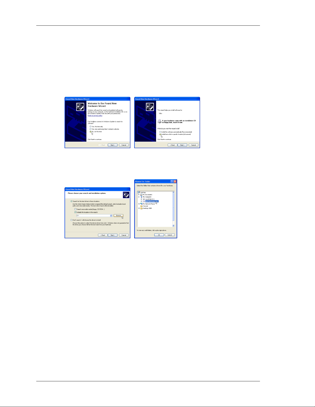
INSTALLING THE USB DRIVERS
When you first connect a Vlinx Fieldbus Gateway to your PC using a USB cable, Windows
Hardware Wizard will appear. Before continuing, make sure that the CD containing Vlinx
Fieldbus Gateway Manager is in the CDROM drive of your PC.
If connected to the Internet, Windows will ask to connect to Windows Update. Select, No, not
this time, and then select Install from a specific location (Advanced) on the subsequent dialog.
When the Hardware Wizard continues, choose the Browse option, and point the Wizard at
your CDROM drive. Click OK to finish the USB driver installation.
Windows XP users should note that Fieldbus Gateway Manager’s USB drivers have not been
digitally signed by Microsoft, and you will therefore see a dialog offering you the chance to
stop the installation. You should be sure to select the Continue option to indicate that you do
indeed wish to install the drivers.
If you do not have the CD that came with the Vlinx Fieldbus Gateway, but you have
previously installed Vlinx Fieldbus Gateway Manager, follow the same steps shown above,
but rather than pointing to the CDROM drive, browse and point to the following folder…
C:\Program Files\B&B Electronics\Vlinx\Vlinx Fieldbus Gateway Manager\Device.
PAGE 2
Page 19
FIELDBUS GATEWAY MAN AGER BASICS MAIN SCREEN ICONS
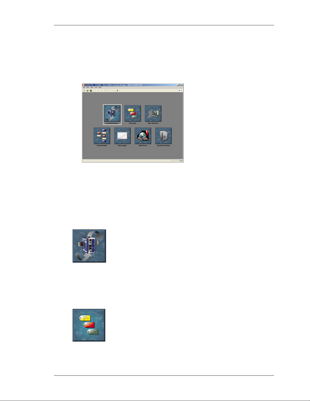
FIELDBUS GATEWAY MANAGER BASICS
To run Fieldbus Gateway Manager, select the Fieldbus Gateway Manager icon from the B&B
Electronics folder on the Programs section of your Start Menu. The main Fieldbus Gateway
Manager screen will appear, showing the icons that are used to configure the various aspects
of the gateway’s behavior…
The software is designed such that the first three icons are the only ones required for the
majority of simple applications. The remainder of the icons provide access to the Gateway’s
more advanced features, such as programming, data logging and the Gateway’s web server.
MAIN SCREEN ICONS
The sections below provide an overview of each icon in turn…
C
OMMUNICATIONS
This icon is used to specify which protocols are to be used on the Gateway’s
serial ports and on the Ethernet port. Where master protocols are used (ie.
protocols by which the Gateway initiates data transfer to and from a remote
device) you can also use this icon to specify one or more devices to be
accessed. Where slave protocols are used (ie. protocols by which the
Gateway receives and responds to requests from remote devices or computer systems) you
can specify which data items are to be exposed for read or write access. You can also use this
icon to move data between one remote device and another via Fieldbus Gateway Manager’s
protocol converter.
ATA TAGS
D
This icon is used to define the data items to be accessed within the remote
devices, or to define internal data items to store information within the
terminal itself. Each tag has a variety of properties associated with it. The
most basic property is formatting data, which is used to specify how the data
held within a tag is to be shown on the terminal’s display, and on such
things as web pages. By specifying this information within the tag, Fieldbus Gateway
Manager removes the need for you to re-enter formatting data each time a tag is displayed.
REVISION 1 PAGE 3
Page 20
MAIN SCREEN ICONS VLINX FIELDBUS GATEWAY MANAGER USER MANUAL
More advanced tag properties include alarms that may activate when various conditions
relating to the tag occur, or triggers, which perform programmable actions on similar
conditions.
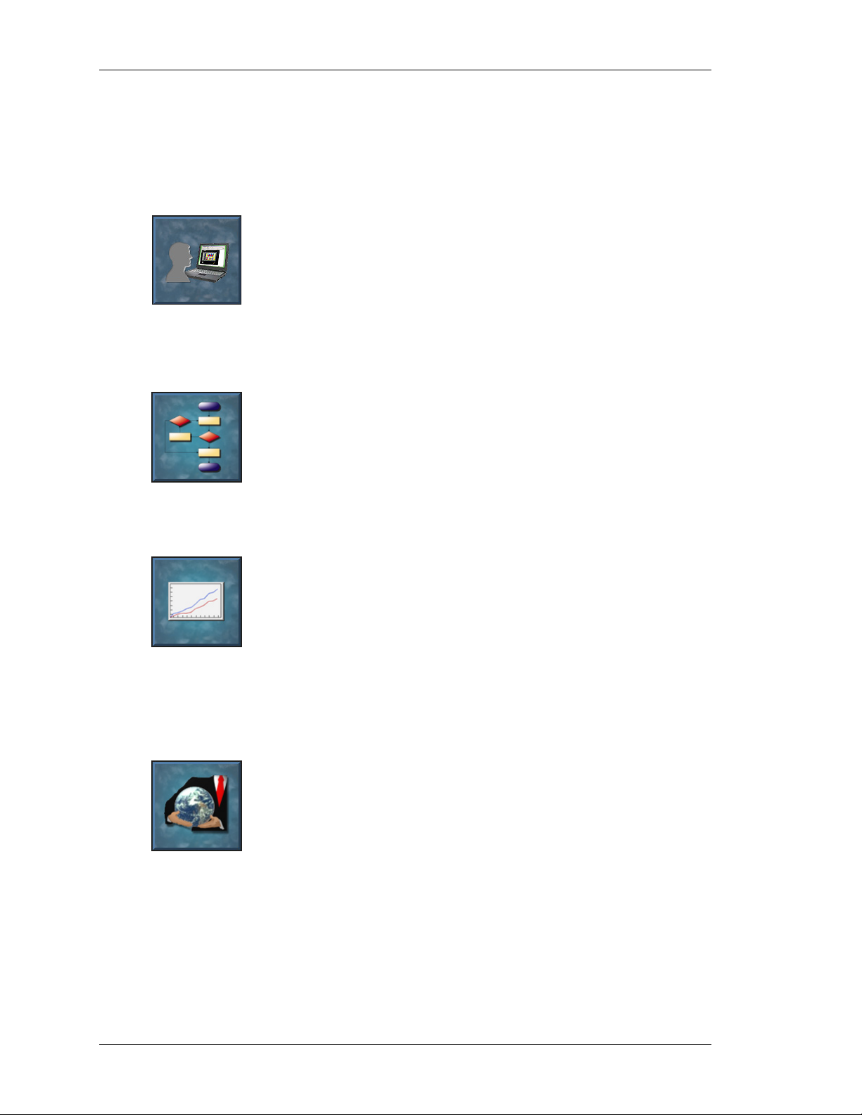
SER INTERFACE
U
This icon is used to create and edit display pages, and to specify what
actions should be taken when the Gateway’s keys are pressed, released or
held down. The page editor allows you to display various graphical items
known as primitives. These vary from simple items, such as rectangles and
lines, to more complex items that can be tied to the value of a particular tag
or expression. By default, such primitives use the formatting information defined when the
tag was created, but this information can be overridden if required.
ROGRAMMING
P
This icon is used to create and edit programs using the software’s unique Clike programming language. These programs can perform complex decision
making or data manipulation operations based upon any data items within
the system. They serve to extend the functionality of Fieldbus Gateway
Manager beyond that of the standard functions included in the software,
thereby ensuring that even the most complex applications can be tackled with ease.
ATA LOGGER
D
This icon is used to create and manage data logs, each of which can record
any number of variables to the Gateway’s CompactFlash card. Data may be
recorded as quickly as once per second. The recorded values will be stored
in CSV (comma separated variable) files that can easily be imported into
applications such as Microsoft Excel. The files can be accessed by
swapping-out the CompactFlash card, by mounting the card as a drive on a PC connected on
the Gateway’s USB port, or by accessing them via Fieldbus Gateway Manager’s web server
via the Ethernet port.
EB SERVER
W
This icon is used to configure Fieldbus Gateway Manager’s web server and
to create and edit web pages. The web server is capable of providing remote
access to the Gateway via a number of mechanisms. First, you can use
Fieldbus Gateway Manager to create automatic web pages which contain
lists of tags, each formatted according to the tag’s properties. Second, you
can create a custom site using a third party HTML editor such as Microsoft FrontPage, and
then include special text to instruct Fieldbus Gateway Manager to insert live tag values.
Finally, you can enable the software’s unique remote access and control feature, which allows
a web browser to view the Gateway’s display and control its keyboard. The web server can
also be used to access CSV files from the Data Logger.
PAGE 4
Page 21
FIELDBUS GATEWAY MAN AGER BASICS SELECTING A MODEL
SECURITY MANAGER
This icon is used to create and manage the various users of the Gateway, as
well as the access rights granted to them. Real names may also be given,
which allows the security logger to record not only what data was changed
and when, but also by whom the data was changed. The rights required to
modify a particular tag, or to access a page, are set via the security
properties of the individual item.
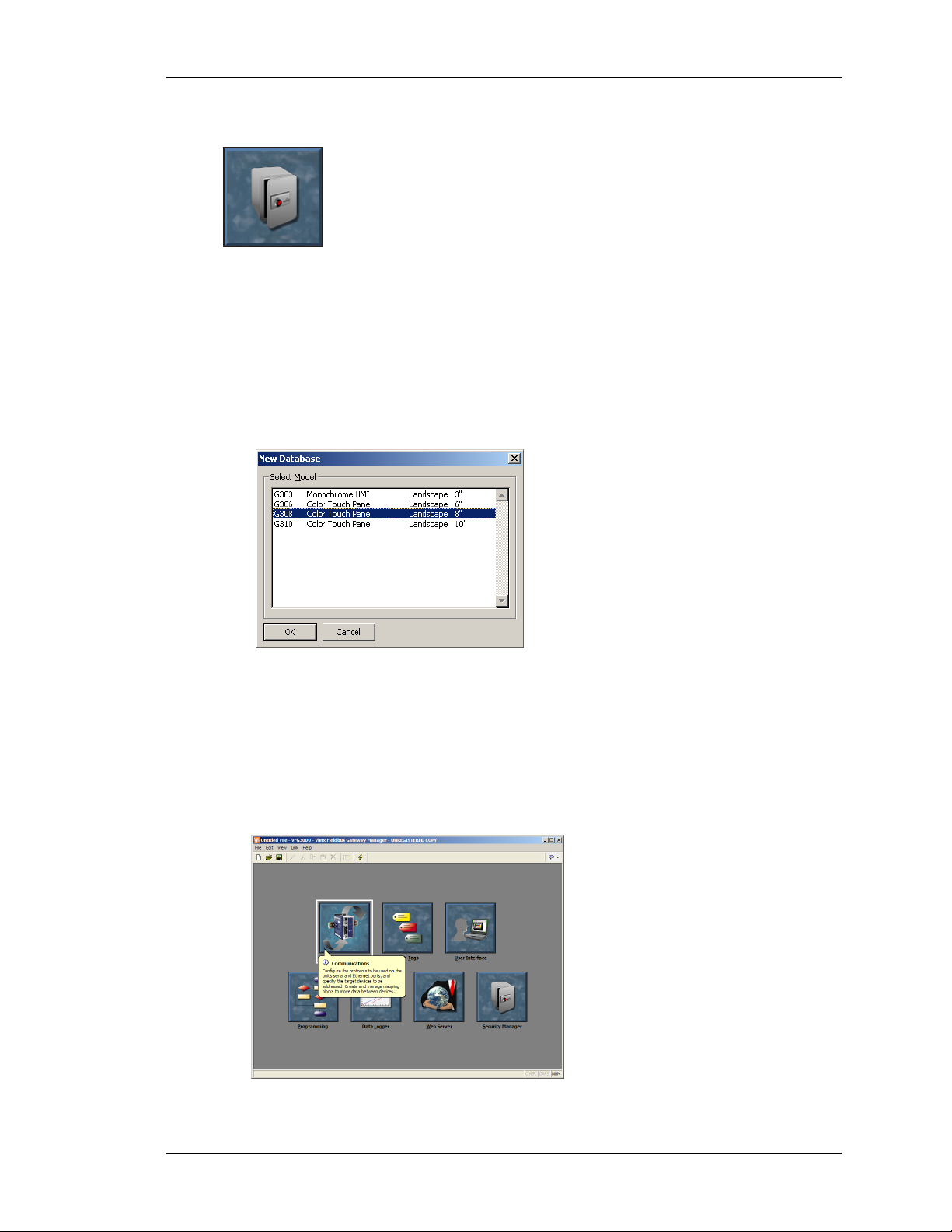
SELECTING A MODEL
When Fieldbus Gateway Manager first starts, it will assume that you are continuing to work
with the same model as was used by the last loaded database. If Fieldbus Gateway Manager
has not been previously executed, it will assume you are working with a VFG1000. If you
want to select a new model, select the New command from the File menu. The following
dialog will appear…
The dialog lists the models supported by the current version of the software, providing a
description of each terminal and the dimensions of its display. Selecting a terminal will create
a blank database, and reconfigure Fieldbus Gateway Manager to work with that specific
model.
USING BALLOON HELP
Fieldbus Gateway Manager provides a useful feature called Balloon Help...
REVISION 1 PAGE 5
Page 22
WORKING WITH DATABASES VLINX FIELDBUS GATEWAY MANAGER USER MANUAL
This feature allows you to see help information for each icon in the main menu, or for each
field in a dialog box or window. It is controlled via the icon at the right-hand edge of the
toolbar, and can be configured to three modes, namely “Do Not Display”, in which case
balloon help is disabled; “When Mouse Over”, in which case help is displayed when the
mouse pointer is held over a particular field for a certain period of time; or “When Selected”,
in which case help is always displayed for the currently selected field.
WORKING WITH DATABASES
Fieldbus Gateway Manager stores all the information about a particular Gateway’s
configuration in what is called a database file. These files have the extension of
CD2, although
Windows Explorer will hide this extension if it is left in its default configuration. Fieldbus
Gateway Manager database files differ from those used by previous B&B Electronics
Fieldbus Gateways, in that they are text files which are thus far easier to recover in the case of
accidental corruption. Databases are manipulated via the commands found on the File menu.
These commands are standard for all Windows applications, and need no further explanation.
The exception is Save Image, which will be covered later.
DOWNLOADING TO A VLINX FIELDBUS GATEWAY
Fieldbus Gateway Manager database files are downloaded to the Fieldbus Gateway by means
of the Link menu. The download process typically takes only a few seconds, but can take
somewhat longer on the first download if Fieldbus Gateway Manager has to update the
firmware in the Fieldbus Gateway, or if the Gateway does not contain an older version of the
current database. After this first download, however, Fieldbus Gateway Manager uses a
process known as incremental download to ensure that only changes to the database are
transferred. This means that changes can be made in seconds, thereby reducing your
development cycle time and simplifying the debugging process.
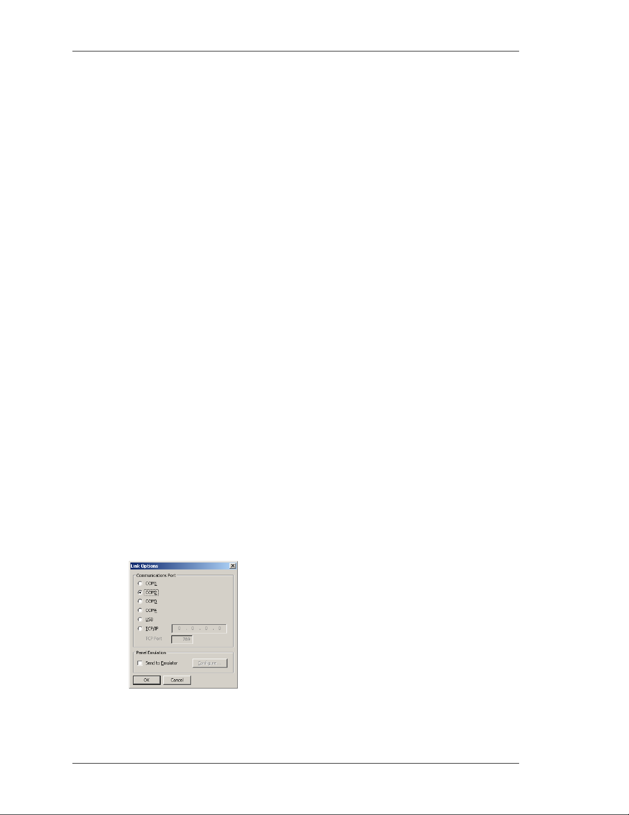
ONFIGURING THE LINK
C
The programming link between the PC and the Gateway is made using an RS-232 serial port,
a USB port or a TCP/IP connection. While TCP/IP connections are typically made via the
Gateway’s Ethernet port, they may also be established via a dial-in link. Before downloading,
you should use the Link-Options command to ensure that you have the method selected…
PAGE 6
Page 23
FIELDBUS GATEWAY MAN AGER BASICS DOWNLOADING TO A VLINX FIELDBUS GATEWAY
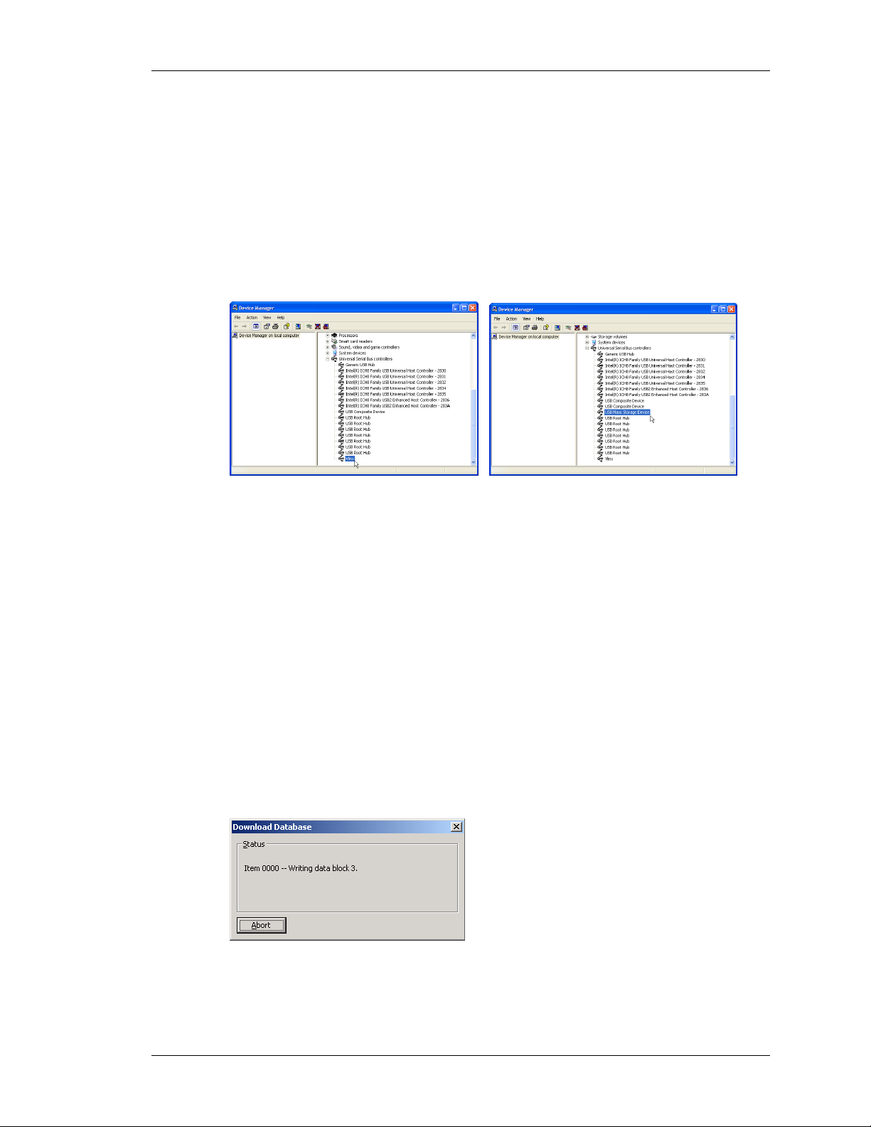
VERIFYING THE USB LINK
If you are using USB, you might also want to ensure that the Gateway’s USB drivers have
been correctly installed. To do this, connect the Fieldbus Gateway, and, if the drivers have not
previously been installed, follow the instructions at the start of this manual. Then, open the
Device Manager for your operating system, and expand the USB icon to show the icon for the
Vlinx device. Ensure that this icon does not display a warning symbol. If it does, remove the
device, unplug and reconnect the Fieldbus Gateway, and verify that you have correctly
followed the driver installation procedure. The illustrations below show typical Device
Manager views with the CompactFlash dismounted and mounted, respectively….
S
ETTING THE IP ADDRESS
If you are using a TCP/IP connection, you should enter the IP address of the target device in
the appropriate field in the dialog box. If you leave the IP address as 0.0.0.0, Fieldbus
Gateway Manager will examine the currently loaded database to see if the Gateway’s address
can be determined from the configuration information. This feature removes the need to
change the IP addresses when switching between databases intended for different terminals.
ENDING THE DATABASE
S
Once the link is configured, the database can be downloaded using either the Link-Send or
Link-Update commands. The former will send the entire database, whether or not individual
objects within the file have changed. The latter will only send changes, and will typically take
a much shorter period of time to complete. The Update command is typically the only one
that you will need, as Fieldbus Gateway Manager will automatically fall-back to a complete
send if the incremental download fails for any reason. As a shortcut, note that you can access
Link Update via the lightning-bolt symbol on the toolbar, or via the
F9 key on the PC.
Note that downloading via TCP/IP relies on a CompactFlash card being installed in the
Gateway if the device’s firmware is to be upgraded. Since you may want to perform such
REVISION 1 PAGE 7
Page 24
DOWNLOADING TO A VLINX FIELDBUS GATEWAY VLINX FIELDBUS GATEWAY MANAGER USER MANUAL
upgrades at some point in time, it is highly recommended that you install a CompactFlash
card in any device to which TCP/IP downloads are likely to be performed.
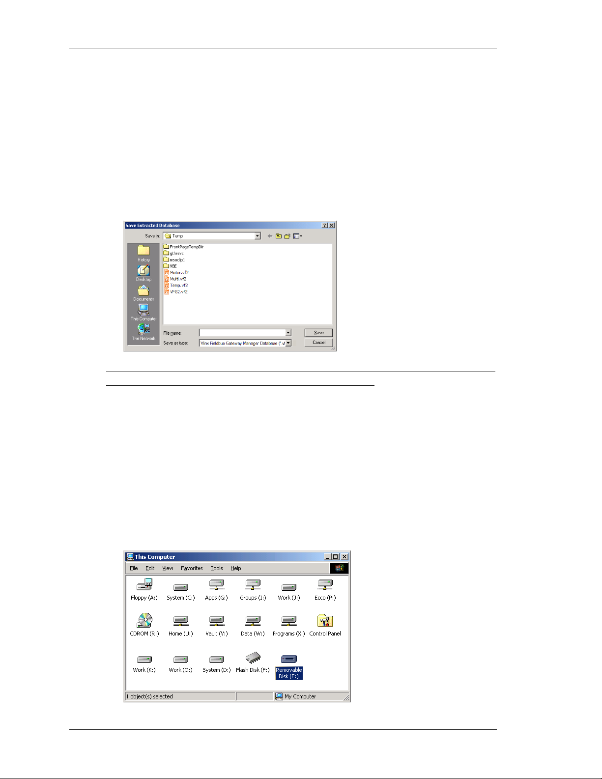
XTRACTING DATABASES
E
The Link-Support Upload command can be used to instruct Fieldbus Gateway Manager
whether or not it should include the information necessary to support database upload when
sending a database to a Fieldbus Gateway. Supporting upload will slow the download process
somewhat and may fail with extremely large databases containing many embedded images,
but it will ensure that should you lose your database file, you will be able to extract an
editable image from the terminal.
Note that if you lose your database file and you do not have upload support enabled, you will
not be able to reconstruct your file without starting from scratch. To extract a database from a
Gateway, use the Link-Extract command. This command will upload the database, and then
prompt you for a name under which to save the file. The file will then be opened for editing.
OUNTING THE COMPACTFLASH
M
If you are connected to a Fieldbus Gateway via the USB port, you can instruct Fieldbus
Gateway Manager to mount the Gateway’s CompactFlash card as a drive within Windows
Explorer. You can use this functionality to save files to the card or to read information from
the Data Logger. The drive is mounted and dismounted by sending commands using the
Mount Flash and Dismount Flash options on the Link menu. Once a command has been sent,
the Fieldbus Gateway will be reset, and Windows will refresh the appropriate Explorer
windows to show or hide the CompactFlash drive.
PAGE 8
Page 25

FIELDBUS GATEWAY MAN AGER BASICS DOWNLOADING TO A VLINX FIELDBUS GATEWAY
Note that some caution is required when mounting the CompactFlash card...
• When the card is mounted, the Gateway will periodically inform the PC if data
on the card has been modified. This means that both the PC and the Gateway
will suffer performance hits if the card is mounted during data logging
operations for longer than necessary.
• If you write to the CompactFlash card from your PC, the Gateway will not be
able to access the card until Windows releases its “lock” on the card’s contents.
This may take up to a minute, and will restrict data logging operations during
that time, and prevent access to custom web pages. Fieldbus Gateway Manager
will use the Gateway’s RAM to ensure that no data is lost, but if too many writes
are performed such that the card is kept locked for four minutes or more, data
may discarded. Note that Windows 98 is particularly bad at keeping the card
locked when there is no need for it. Windows 2000 or Windows XP is thus the
operating system of choice when using this feature.
• You should never
attempt to use Windows to format a CompactFlash card that
you have mounted via the Gateway, whether it be via Explorer or from the
command prompt. Windows does not correctly lock the card during format
operations, and the format may thus be unreliable and lead to subsequent data
loss. See below for details of how to format a card in a reliable manner.
ORMATTING THE COMPACTFLASH
F
The preferred method of formatting a card is via the Format Flash command on the Link
menu. Selecting this command will explain that the formatting process will destroy all the
data stored on the CompactFlash card and offer you a chance to cancel the operation. If you
elect to continue, the Fieldbus Gateway will be instructed to format the card. Note that this
process may take several minutes for a large card. Slow formats on Gateways that are
performing data logging may therefore result in gaps in the recorded data.
A less attractive method of formatting a card is via a dedicated CompactFlash drive connected
to your PC. If you use this method, be sure to instruct Windows to format the card using
FAT16. For very small or very large cards, Windows will most likely choose the wrong
format by default. Worse still, some versions of Windows Explorer will not allow you to
override the default format, forcing you to use the command line version
ENDING THE TIME AND DATE
S
FORMAT instead.
The Link-Send Time command can be used to set the Gateway’s clock to match that of the
PC on which Fieldbus Gateway Manager is executing. Obviously, make sure your clock is
right before you do this!
REVISION 1 PAGE 9
Page 26
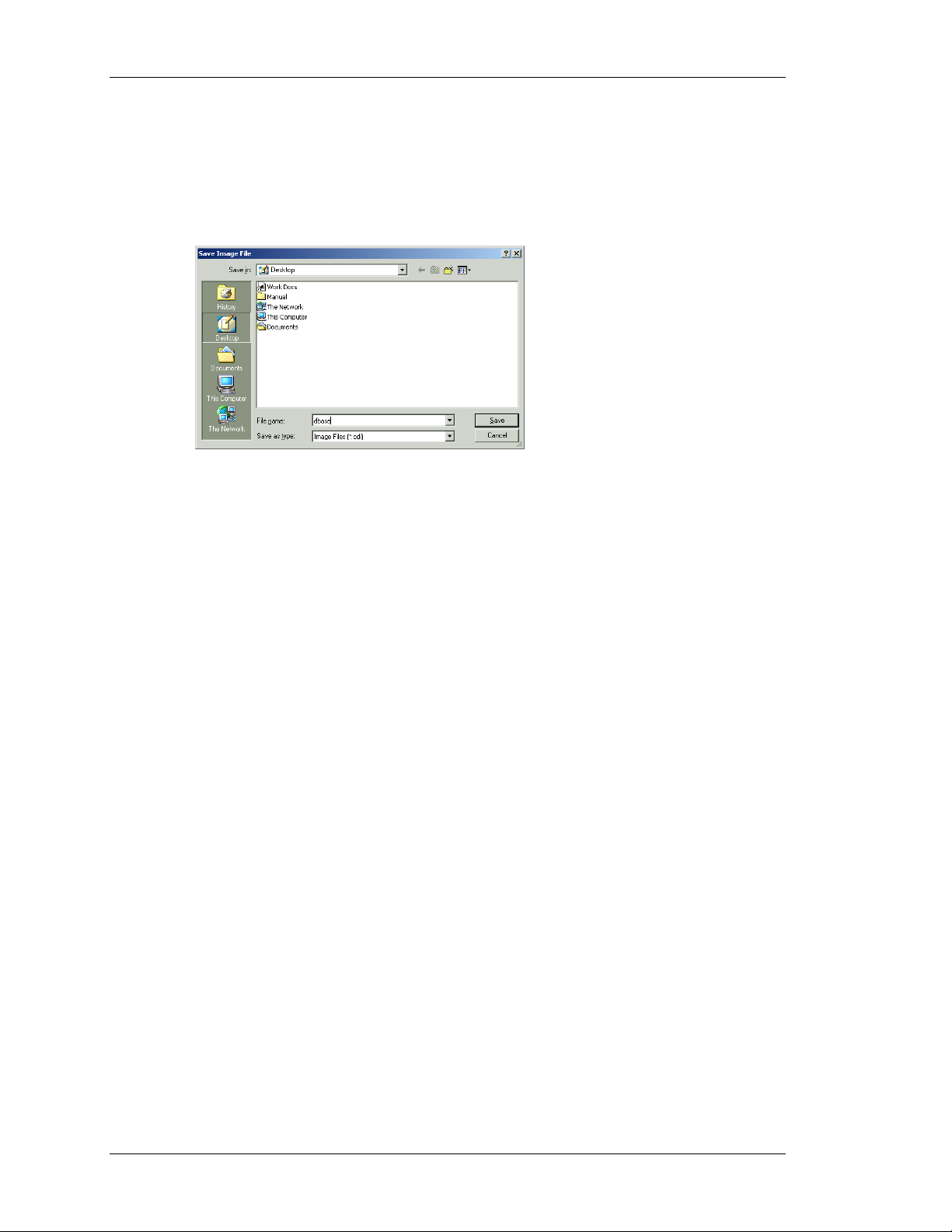
UPDATING VIA COMPACTFLASH VLINX FIELDBUS GATEWAY MANAGER USER MANUAL
UPDATING VIA COMPACTFLASH
If you need to update the database within a unit that is already installed at a customer’s site,
Fieldbus Gateway Manager allows you to save a copy of the database to a CompactFlash
card, ship that card to your customer, and have the Gateway load the database from that card.
The process is performed via the Save Image command on the File menu.
The Save Image command will create a Fieldbus Gateway Manager database image file with
CDI extension. It will also save a copy of the current Gateway firmware to a file with a BIN
a
extension. The image file must be given the name
must be placed in the root directory of a CompactFlash card. To update a Fieldbus Gateway,
power down the unit, insert the CompactFlash card bearing the two files, and reapply power
to the unit. The Gateway’s boot loader will first check whether it needs to upgrade the unit’s
firmware, and once this process has been completed, the Fieldbus Gateway Manager runtime
application will load the database stored on the card. The CompactFlash card can then be
removed or left in place as required.
DBASE.CDI, and both it and the BIN file
GURU MEDITATION CODES
If a problem with the Fieldbus Gateway Manager runtime application within the Gateway
results in it being reset, the condition that caused the fault will be logged. When the Gateway
restarts, this information will be displayed in the form of a Guru Meditation Code on the
virtual HMI. A typical code will have the format…
The message can be accepted by pressing the F1 key, at which point the Gateway will resume
normal operation. Note that communications, data logging and the web server are still active
when the GMC is displayed—only the user interface is interrupted. This means that system
disruption is minimized, and functions such as protocol conversion continue to operate.
Before accepting the message, you may wish to write down the code. You may then email it
to B&B Electronics technical support, so that one of our technical gurus can meditate on this
information in order to track-down the cause of the problem. You may also want to email a
copy of the Gateway’s database, and describe what you were doing when the terminal
crashed.
03-2004-1BE4-205
PAGE 10
Page 27

FIELDBUS GATEWAY MAN AGER BASICS GURU MEDITATION CODES
REVISION 1 PAGE 11
Page 28

Page 29
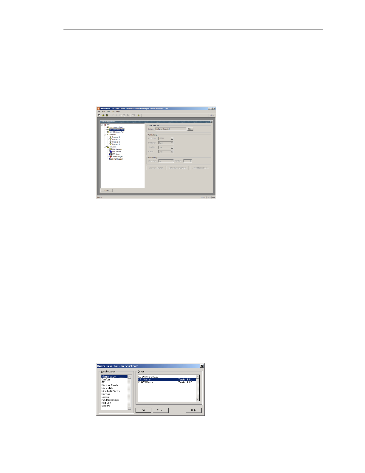
CONFIGURING COMMUNICATIONS SERIAL PORT USAGE
CONFIGURING COMMUNICATIONS
The first stage of creating a Fieldbus Gateway Manager database is to configure the
communications ports of the Fieldbus Gateway to indicate which protocols you want to use,
and which remote devices you want to access. These operations are performed from the
Communications window, which is opened by selecting the first icon of the Fieldbus
Gateway Manager main screen.
As can be seen, the Communications window lists the unit’s available ports in the form of a
tree structure. Fieldbus Gateways have three primary serial ports, with the option to add a
further two ports in the form of an expansion card. They also provide a single Ethernet port
that is capable of running four communications protocols simultaneously.
SERIAL PORT USAGE
When deciding which of the Gateway’s serial ports to use for communications, note that…
• The unit’s programming port may be used as an additional communications port,
but it will obviously not be available for download if it is so employed. This is
not an issue if the USB port is used for such purposes, and it is highly
recommended that you use this method of download if you want to connect
serial devices via the programming port.
SELECTING A PROTOCOL
To select a protocol for a particular port, click on that port’s icon in the left-hand pane of the
Communications window, and press the Edit button next to the Driver field in the right-hand
pane. The following dialog box will appear…
REVISION 1 PAGE 13
Page 30
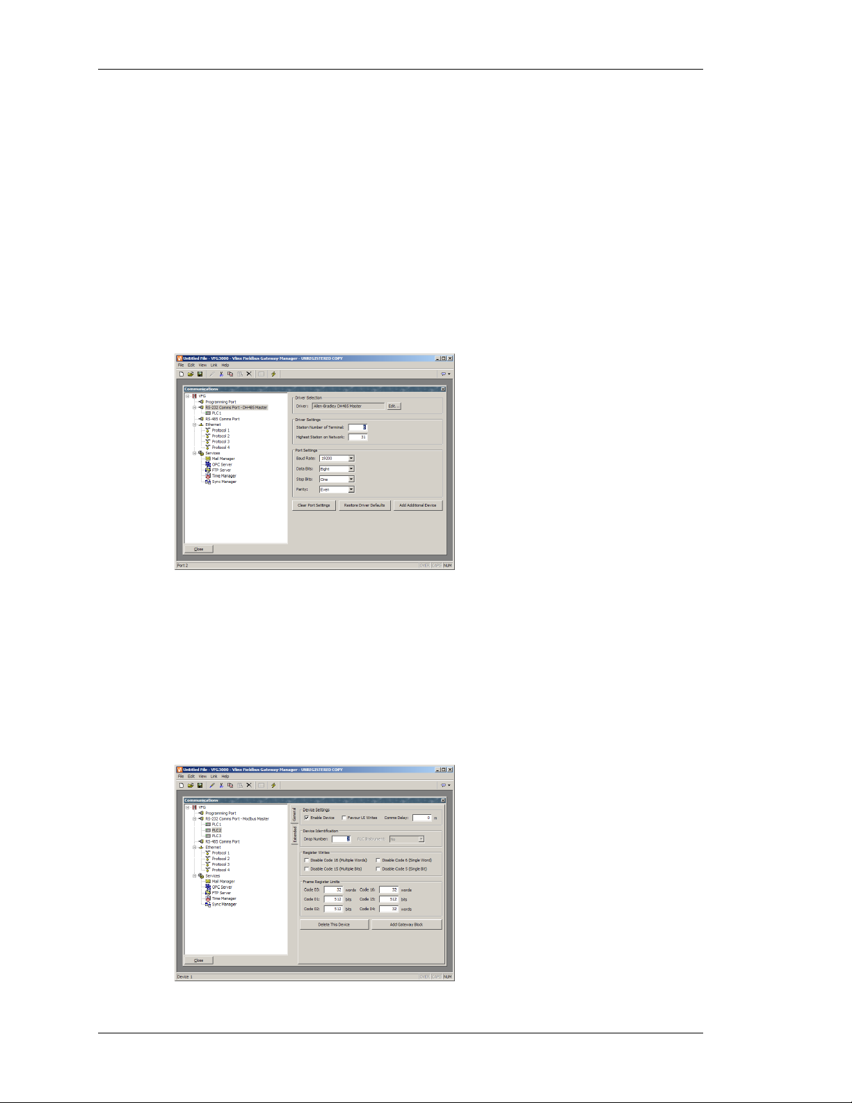
PROTOCOL OPTIONS VLINX FIELDBUS GATEWAY MANAGER USER MANUAL
Select the appropriate manufacturer and driver, and press the OK button to close the dialog
box. The port will then be configured to use the appropriate protocol, and a single device icon
will be created in the left-hand pane. If you are configuring a serial port, the various Port
Settings fields (Baud Rate, Data Bits, Stop Bits and Parity) will be set to values appropriate to
the protocol in question. You should obviously check these settings to make sure that they
correspond to the settings for the device to be addressed.
PROTOCOL OPTIONS
Some protocols require additional configuration of parameters specific to that protocol. These
appear in the right-hand pane of the Communications window when the corresponding port
icon is selected. The example below shows the additional parameters for the Allen-Bradley
DH-485 driver, which appear under the Driver Settings section of the window.
WORKING WITH DEVICES
As mentioned above, when a communications protocol is selected, a single device is created
under the corresponding port icon. In the case of a master protocol, this represents the initial
remote device to be addressed via the protocol. If the protocol supports access to more than
one device, you can use the Add Additional Device button included with the port icon’s
properties to add further target devices. Each device is represented via an icon in the left-hand
pane of the Communications window, and, depending on the protocol in question, may have a
number of properties to be configured…
PAGE 14
Page 31

CONFIGURING COMMUNICATIONS ETHERNET CONFIGURATION
In the example above, the Modbus Universal Master protocol has been selected, and two
additional devices have been created, indicating that a total of three remote devices are to be
accessed. The right-hand pane of the window shows the properties of a single device. The
Enable Device property is present for devices for all protocols, while the balance of the fields
are specific to the protocol that has been selected. Note that the devices are given default
names by Fieldbus Gateway Manager when they are created. These names may be changed
by selecting the appropriate icon in the left-hand pane, and simply typing the new device
name.
ETHERNET CONFIGURATION
The Gateway’s Ethernet port is configured via the Ethernet icon in the left-hand pane of the
Communications window. When this icon is selected, the following settings are displayed…
IP
PARAMETERS
The Port Mode field controls whether or not the port is enabled, and the method by which the
port is to obtain its IP configuration. If DHCP mode is selected, the Gateway will attempt to
obtain an IP address and associated parameters from a DHCP server on the local network. If
the unit is configured to use slave protocols or to serve web pages, this option will only make
sense if the DHCP server is configured to allocate a well-known IP address to the MAC
address associated with the unit, as otherwise, users will not be sure how to address the
Gateway!
If the more common Manual Configuration mode is selected, the IP Address, Network Mask
and Gateway fields must be filled out with the appropriate information. The default values
provided for these fields will almost never be suitable for your application! Be sure to consult
your network administrator when selecting appropriate values, and be sure to enter and
download these values before connecting the Gateway to your network. If you do not follow
this advice, it is possible—although unlikely—that you will cause problems on your network.
ROUTING
IP
The IP Routing option can be used to enable or disable the routing of IP packets between the
Ethernet port and any PPP connections made to or by the Gateway. You should not enable
this option unless you understand the implications of allowing such routing. Please refer to
the Advanced Communications chapter for more information.
REVISION 1 PAGE 15
Page 32

ETHERNET CONFIGURATION VLINX FIELDBUS GATEWAY MANAGER USER MANUAL
PHYSICAL LAYER
The Physical Layer options control the type of connection that the Gateway will attempt to
negotiate with the hub to which it is connected. Generally, these options can be left in their
default states, but if you have trouble establishing a reliable connection, especially when
connecting directly to a PC without an intervening hub or switch, consider turning off both
Full Duplex and High Speed operation to see if this solves the problem.
EMOTE UPDATE
R
The Remote Update option is used to enable or disable firmware and configuration download
via TCP/IP. As noted in an earlier section, remote firmware updates over TCP/IP require the
units to be fitted with a CompactFlash card. Since downloads will more than likely involve a
firmware update at some point, such a card is highly recommended when using this feature.
ROTOCOL SELECTION
P
Once the Ethernet port has been configured, you can select the protocols that you wish to use
for communications. Up to four protocols may be used at once, and many of these protocols
will support multiple remote devices. This means that you have several options when
deciding how to mix protocols and devices to achieve the results you want.
For example, suppose you want to connect to two remote slave devices using Modbus over
TCP/IP. Your first option is to use two of the Ethernet port’s protocols, and configure both as
Modbus TCP/IP Masters, with a single device attached to each protocol...
PAGE 16
Page 33

CONFIGURING COMMUNICATIONS SLAVE PROTOCOLS
For most protocols, this will produce higher performance, as it will allow simultaneous
communications with the two devices. It will, however, consume two of the four protocols,
limiting your ability to connect via additional protocols in complex applications. Your second
option is therefore to use a single protocol configured as a Modbus TCP/IP Master, but to add
a further device so that both slaves are accessed via the same driver…
This will typically produce slightly reduced performance, as Fieldbus Gateway Manager will
poll each device in turn, rather than talking to both devices at the same time. It will, however,
conserve Ethernet protocols, allowing more complex applications without running out of
resources.
SLAVE PROTOCOLS
For master protocols (ie. those where the Gateway initiates communication) there is no
further configuration required under the Communications icon. For slave protocols (ie. those
where the Gateway receives and responds to remote requests), however, the process is
slightly more complex, as you must also indicate what data you wish to expose for remote
access.
ELECTING THE PROTOCOL
S
As with master protocols, the first stage is to select the protocol for the communications port
that you wish to use. The example below shows the Gateway’s RS-232 port configured for
operation with the Modbus ASCII Slave protocol…
REVISION 1 PAGE 17
Page 34

SLAVE PROTOCOLS VLINX FIELDBUS GATEWAY MANAGER USER MANUAL
Note that a single device has been automatically created for the protocol. In the case of master
protocols, this represents the remote device that the Gateway will access. In this case, though,
the device represents the Modbus slave that the Gateway will itself embody. This means that
only a single device is required, and that things such as the station number to which the
Gateway will respond are normally configured via the port settings rather than those of the
device.
DDING GATEWAY BLOCKS
A
Having configured the protocol, you must now decide what range of addresses you want the
slave protocol to expose. In this example, we want to use Modbus registers
40008 to allow read and write access to certain data items in our database. We begin by
40001 through
selecting the device icon in the left-hand pane of the Communications window, and clicking
the Add Gateway Block button in the right-hand pane. An icon to represent Block 1 will
appear, and selecting it will show the following settings…
In the example above, we have configured the Start Address to
40001 to indicate that this is
where we want the block to begin. We have also configured the Block Size to eight so as to
allocate one Modbus register for each tag we want to expose. Finally, we have configured the
Direction as Device to VFG, to indicate that we want remote devices to be able to read and
write data items exposed via this block.
PAGE 18
Page 35

CONFIGURING COMMUNICATIONS SLAVE PROTOCOLS
ADDING ITEMS TO A BLOCK
Once the block has been created and its size defined, entries appear in the left-hand pane of
the window to represent each of the registers that the block exposes to remote access. When
one of these entries is selected, the right-hand pane shows a list of available data items,
comprising both tags from within your database, and data registers from any master
communications devices that you have configured…
To indicate that you want a particular register within your gateway block to correspond to a
particular data item, simply drag that item from the right-hand pane to the left-hand pane,
dropping it on the appropriate gateway block entry. The example above shows how the first
four registers in the block have been mapped to tags called
that accesses to
A
CCESSING INDIVIDUAL BITS
40001 through 40004 should be mapped to the respective variables.
Tank1 through Tank4, indicating
If your application requires it, you can expand individual elements within a Gateway Block to
their constituent bits, and map a different data item to each bit. To do this, right-click on the
element in question, and select Expand from the resulting pop-up menu. The right-hand pane
will be updated to show the individual bits that make up the register, and these can be mapped
using the drag-and-drop process described above.
REVISION 1 PAGE 19
Page 36

PROTOCOL CONVERSION VLINX FIELDBUS GATEWAY MANAGER USER MANUAL
PROTOCOL CONVERSION
In addition to exposing internal data tags via slave protocols, Gateway Blocks can also be
used to expose data that is obtained from other remote devices, or to move data between two
such master devices. This unique protocol conversion feature allows much tighter integration
between elements of your control system, even when using simple, low-cost devices.
ASTER AND SLAVE
M
Exposing data from other devices over a slave protocol is simply an extension of the mapping
process described above, except this time, instead of dragging a tag from the right-hand pane,
you should expand the appropriate master device, and drag across the icon that represents the
registers that you want to expose. You will then be asked for a start address in the master
device, and the number of registers to map, and the mappings will be created as shown.
In this example, registers
exposed for access via Modbus TCP/IP as registers
N7:0 through N7:7 in an Allen-Bradley controller have been
40001 through 40008. Fieldbus Gateway
Manager will automatically ensure that these data items are read from the Allen-Bradley PLC
so as to fulfill Modbus requests, and will automatically convert writes to the Modbus registers
into writes to the PLC. This mechanism allows even simple PLCs to be connected on an
Ethernet network.
ASTER AND MASTER
M
PAGE 20
Page 37

CONFIGURING COMMUNICATIONS DATA TRANSFORMATION
To move data between two master devices, simply select one of the devices, and create a
Gateway Block for that device. You can then add references to the other device’s registers
just as you would when exposing data on a slave protocol. Again, C2 will automatically read
or write the data as required, transparently moving data between the devices. The example
above shows how to move data from a Mitsubishi FX into an SLC-500.
HICH WAY AROUND?
W
One question that may occur to you is whether you should create the Gateway Block within
the Allen-Bradley device, as in this example, or within the Mitsubishi device. The first thing
to note is that there is no need to create more than a single block to perform transfers in a
single direction. If you create a block in AB to read from MITFX, and a block in MITFX to
write to AB, you’ll simply perform the transfer twice and slow everything down! The second
observation is that the decision as to which device should “own” the Gateway Block is
essentially arbitrary. In general, you should create your blocks so as to minimize the number
of blocks in the database. This means that if the registers in the Allen-Bradley lay within a
single range, but the registers in the Mitsubishi are scattered all over the PLC, the Gateway
Block should be created within the Allen-Bradley device so as to remove the need to create
multiple blocks to access the different ranges of the Mitsubishi device.
DATA TRANSFORMATION
You may also use Gateway Blocks to perform math operations that your PLC might not
otherwise be able to handle. For example, you may want to read a register from the PLC,
scale it, take the square root, and write it back to another PLC register. To accomplish this,
refer to the section on Data Tags, and create a mapped variable to represent the input value
that will be read from the device. Then, create a formula to represent the output value, setting
the expression so as to perform the required math. You can then create a Gateway Block
targeted at the required output register, and drag the formula across to instruct Fieldbus
Gateway Manager to write the derived value back to the PLC.
REVISION 1 PAGE 21
Page 38

Page 39
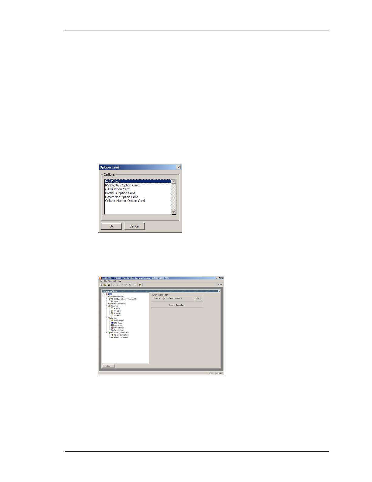
ADVANCED COMMUNICATIONS USING EXPANSION CARDS
ADVANCED COMMUNICATIONS
This chapter explains how to use some of the more advanced communications features that
are supported by Fieldbus Gateway Manager. Simple applications may not require these
features, and you may thus choose to skip this chapter and return to it later.
USING EXPANSION CARDS
Each Fieldbus Gateway is capable of hosting an expansion card to provide additional
communications facilities. Hardware installation instructions are provided with each card, so
please refer to the supplied data sheet for information on how to fit the card to the Gateway.
Once the card is installed, configuration is performed by selecting the VFG icon in the lefthand pane of the Communications window, and clicking on the Edit button next to the Option
Card property…
Selecting the appropriate card will add an icon to tree shown in the left-hand pane of the
window. This icon will in turn contain icons for the additional port or ports that are made
available by the card. The example below shows a Gateway with a serial expansion card
installed…
The additional ports can be configured by following the instructions supplied in the previous
chapter. Note that the drivers available for a port will depend on the connection type it
supports. For example, the CANOpen expansion card shows a port that will only support
drivers designed for the CAN communication standard.
REVISION 1 PAGE 23
Page 40

SHARING SERIAL PORTS VLINX FIELDBUS GATEWAY MANAGER USER MANUAL
SHARING SERIAL PORTS
All Vlinx Fieldbus Gateways provide a so-called “port sharing” facility that allows either
physical or virtual serial connections to be made to any device connected to the Gateway. For
example, you may be using the Gateway with a small programmable controller, but since the
PLC has only a single serial port, you may find yourself continually swapping cables when
modifying the PLC’s ladder program. By sharing the Gateway’s communications port, you
can send data directly to the PLC, either from another serial port on the Gateway or by means
of a virtual serial connection made over an Ethernet link.
NABLING TCP/IP
E
The first configuration step when using port sharing is to enable the Gateway’s Ethernet port
as described in the previous chapter. While you may not choose to use the virtual serial port
facility, even the local sharing of ports is based upon the TCP/IP protocol, which will not be
available unless Ethernet is enabled. To enable Ethernet, select the Ethernet icon in the
Communications window, and select the required configuration mode. For installations where
Ethernet is not actually being used, you can select Manual Configuration and leave the rest of
the options at their defaults.
HARING THE REQUIRED PORT
S
The next step is to share the required port, which is done by selecting Yes in the Share Port
property and by optionally entering a suitable TCP/IP port number. This number represents
the virtual port that will be used to expose the serial port for access via TCP/IP.
If you leave the port setting at zero, a number of 4000 plus the logical index of the port will
be used. (To obtain the logical index of the port, count the port’s position in the list, noting
that the programming port is always logical port 1.) You may use any number that is not
already used by another TCP/IP protocol. If you are stuck for ideas, we recommend numbers
between 4000 and 4099.
ONNECTING VIA ANOTHER PORT
C
If you want to use another port on the Gateway to route data to the shared port, you must
select the Generic Program Thru driver for that port, and configure this driver with the
PAGE 24
Page 41

ADVANCED COMMUNICATIONS SHARING SERIAL PORTS
TCP/IP port number of the serial port that you have shared. In the example below, we are
routing data from the programming port to a PLC that is connected via the RS-232 comms
port…
Note that the Baud rate and other port settings do not have to be the same as those for the port
which we are sharing. In the configuration shown above, data to and from the programming
software is sent at a higher Baud rate than the data to and from the PLC, with the Gateway
doing the appropriate buffering and conversion.
In this example, to make use of the shared port you would connect a spare serial port on your
PC to the programming port of the Gateway, and configure the PLC programming software to
talk to this COM port. As soon as the PC begins to talk to the PLC, communications between
the Gateway and the PLC will be suspended, and the Gateway’s two ports will be
“connected” in software, such that the PC will appear to be talking directly to the PLC. If no
data is transferred for more than a minute, communications between the Gateway and the
PLC will be resumed.
ONNECTING VIA ETHERNET
C
Rather than using an additional serial port on your PC and on the Gateway, it is possible to
use a third-party utility to create what are known as virtual serial ports on your computer.
These appear to applications to be physical COM ports, but in fact, they send and receive data
to a remote device over TCP/IP. By installing one of these utilities and configuring it to
address the Gateway, you can have serial access to any devices connected to the Gateway
without any additional cabling. Indeed, there is no need to have any physical serial ports
available on the PC at all—something that is very valuable when working with modern
laptops, where a COM port is often an expensive option.
Several third-party virtual serial port utilities are available. On the freeware side, a company
called HW Group (http://www.hw-group.com) provides a utility called HW Virtual Serial
Port. There are also a number of other freeware port drivers available, most of which seem to
be derived from the same source base. On the commercial side, a company called Tactical
Software (http://www.tacticalsoftware.com) offers Serial/IP for about $100 a port.
While the various freeware drivers no doubt have many contented users, we have found that
these drivers have occasional stability problems on certain PCs. Tactical Software’s Serial/IP
REVISION 1 PAGE 25
Page 42

SHARING SERIAL PORTS VLINX FIELDBUS GATEWAY MANAGER USER MANUAL
is thus the only package that we are able to support, and the following information assumes
that you are using this package.
To create a virtual serial port, open Serial/IP’s configuration screen, and select the name of
the COM port you wish to define. This will typically be the first free COM port after those
allocated to the physical ports and modems installed in your PC. Next, enter the IP address of
the Gateway, and enter the TCP/IP port number that you allocated when sharing the port. The
example below is configured as required by the previous samples in this document. Finally,
ensure Raw TCP Connection is selected, and close the Serial/IP dialog.
You will now be able to configure any Windows-based software to use the newly-created
COM port for download. When the software opens the connection, the Gateway will suspend
communications on the shared port, and then data will be exchanged between the PC software
and the remote PLC—just as if they were connected directly! When the port is closed, or if no
data is transferred for a minute, communications will be resumed.
Note that assuming you’ve purchased the appropriate number of licenses for Serial/IP, you
will be able to create as many virtual ports as you need. This means that you can be connected
to multiple devices from the same PC, downloading to each via its respective programming
package—all without plugging or unplugging a single cable. This feature is extremely
valuable when you have many devices in a complex system.
URE VIRTUAL PORTS
P
In some circumstances, you may want to use a spare serial port on a Gateway to provide
access to a remote device that is not otherwise connected to the Gateway. Or you might want
to use such a port to connect to a dedicated programming port on a device, even though the
Gateway is using another port to perform communications with that device. To do this,
configure the port in the usual way, selecting the Virtual Serial Port driver for that port. Then,
share the port as described above. This Virtual Serial Port driver performs no communications
activity of its own, but still allows the device to be shared for remote access.
PAGE 26
Page 43
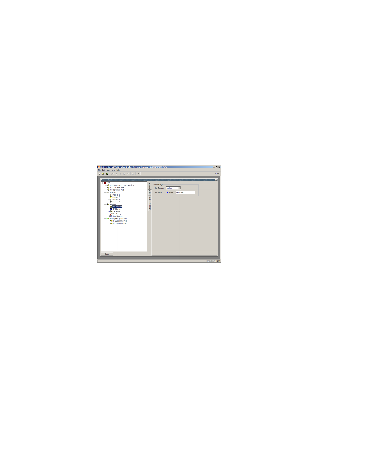
ADVANCED COMMUNICATIONS USING ELECTRONIC MAIL
LIMITATIONS
Note that some PLC programming packages may not work with virtually or physically shared
ports. Issues to watch out for are tight timeouts that do not allow the Gateway time to relay
the data to the PLC; a reliance on sending break signals or on the manipulation of hardware
handshaking lines; or DOS-style port access such that the package cannot “see” the virtual
serial ports. Luckily, these issues are rare, and most packages will happily communicate as if
they were directly connected to the PLC in question. [TBA]
USING ELECTRONIC MAIL
Fieldbus Gateway Manager can be configured to send email messages when alarm conditions
are present, or when notifications needs to be provided of other events within the system. The
methods to be used to deliver email are configured via the Mail icon in the Communications
window…
The properties on a General tab are used to enable or disable mail manager, and to provide a
name for the Fieldbus Gateway. This name will be used within email messages to identify the
originator of the message. Applications will typically use the name of the machine to which
the Gateway is attached, or the name of the site that it is monitoring.
ONFIGURING SMTP
C
The SMTP tab is used to configure the Simple Mail Transport Protocol. This is the standard
protocol used to send email over the Internet or over other TCP/IP networks. SMTP addresses
follow the familiar
name@domain standard.
REVISION 1 PAGE 27
Page 44
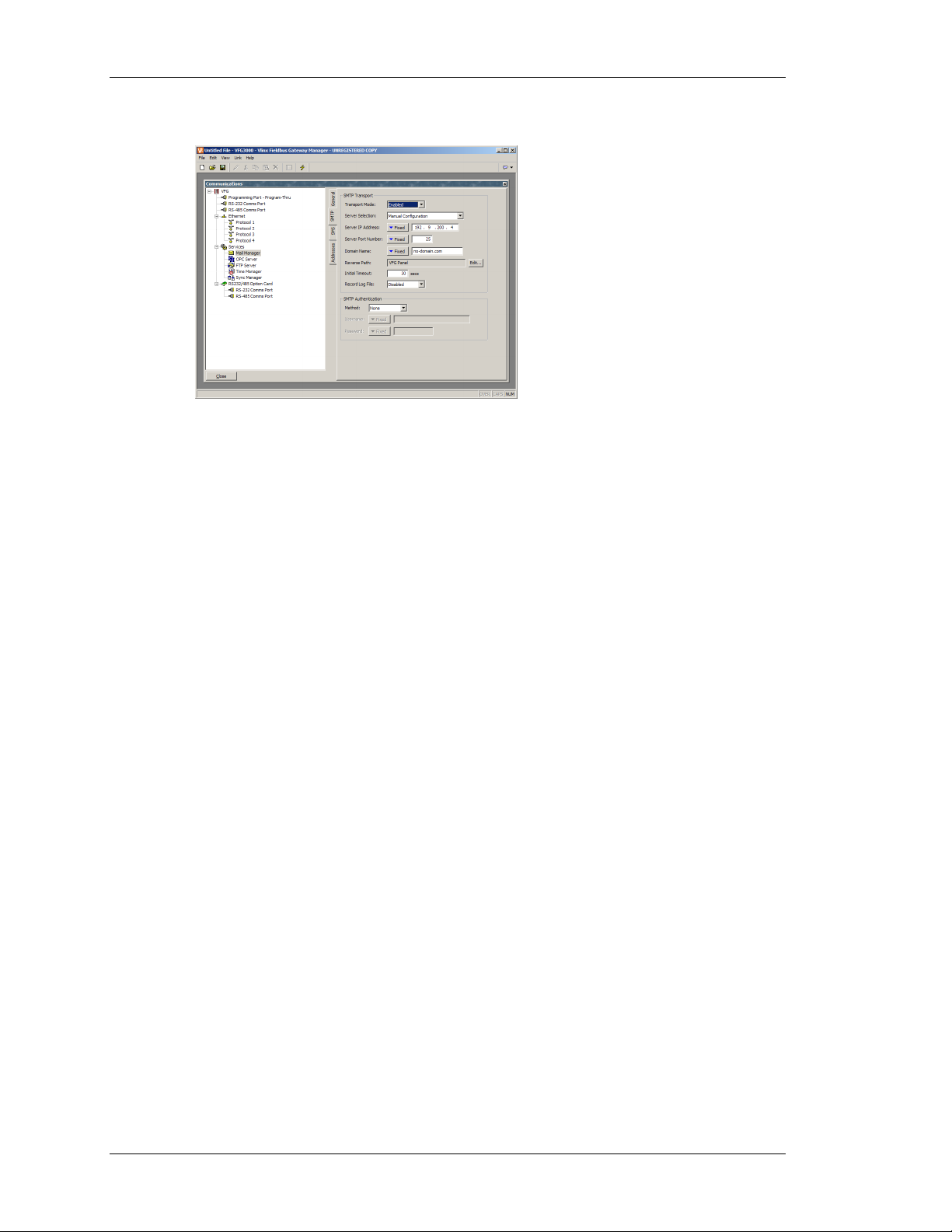
USING ELECTRONIC MAIL VLINX FIELDBUS GATEWAY MANAGER USER MANUAL
The configuration options for the SMTP transport are shown below…
• The Transport Mode property is used to enable or disable the transport. Note that
the mail manager must be enabled via the General tab before the SMTP transport
can be enabled. Note also that either SMTP or SMS must be enabled if the mail
manager is to be able to deliver messages.
• The Server Selection property is used to define how the transport will locate an
SMTP server. If Manual Selection is used, the Server IP Address property should
be used to manual designate a server. If Configured via DHCP is selected, the
unit’s Ethernet port must be configured to use DHCP, and the network’s DHCP
server must be configured to designate an SMTP server via option 69.
• The Server IP Address property is used to designate an SMTP server when
manual server selection is enabled. The server must be configured to accept mail
from the Gateway, and to relay messages if required by the application.
• The Server Port Number property is used to define the TCP port number that
will be used for SMTP sessions. The default value is 25. This value will be
suitable for most applications, and will only need to be adjusted if the SMTP
server has been reconfigured to use another port.
• The Domain Name property is used to specify the domain name that will be
passed to the SMTP server in the HELO command. The vast majority of SMTP
servers ignore this string. In the unlikely event that your SMTP server attempts
to do a DNS lookup to confirm the identity of its client, you may need to enter
something appropriate to your DNS configuration.
• The Reverse Path property is used to specify the email address that will be
supplied as the originator of the messages sent by the Fieldbus Gateway. The
property comprises a display name, and an email address. Since the Gateway is
not capable of receiving messages, the email address will often be set to
something that will return an “undeliverable” message if a reply is sent.
• The Record Log File property can be enabled to keep a log of all SMTP
interactions in the root directory of the CompactFlash card. This file can be
PAGE 28
Page 45

ADVANCED COMMUNICATIONS USING ELECTRONIC MAIL
useful when debugging SMTP operations, but it will tend to degrade
performance slightly.
• The Initial Timeout property is used to specify how long the mail client will wait
for the SMTP server to sent its welcome banner. Some Microsoft servers attempt
to negotiate Microsoft-specific authentication with mail clients, thereby delaying
the point at which the banner appears. You may want to extend this time period
to 2 minutes or more when working with such servers.
ONFIGURING SMS
C
The SMS tab is used to configure the Short Messaging Service. This transport is used to send
text messages to cell phones via a GSM modem. Email addresses for SMS comprise an
international format telephone number, minus the introductory plus-sign. An example address
in the United States would be 17175551234, while an example in the UK would be
441246555555. In each case, the address comprises the country code, followed by the area
code and the subscriber number.
The configuration options for SMS are shown below…
• The Transport Mode property is used to enable or disable the transport. Note that
the mail manager must be enabled via the General tab before the SMS transport
can be enabled. Note also that either SMTP or SMS must be enabled if the mail
manager is to be able to deliver messages.
• The Message Relay property is used to enable or disable the Gateway’s SMS
relay feature. If this feature is enabled, a user who receives an SMS message that
has been sent to several recipients can reply to that message, and have the
Fieldbus Gateway relay the message to the other recipients. This provides a
simple conferencing facility between message recipients.
Note that for the SMS transport to operate, a GSM modem must have been installed on one of
the unit’s serial ports. Refer to later sections of this chapter for details on how to configure
such a modem, and on multiple modems will interact.
REVISION 1 PAGE 29
Page 46

WORKING WITH MODEMS VLINX FIELDBUS GATEWAY MANAGER USER MANUAL
THE ADDRESS BOOK
The Addresses tab is used to define email recipients…
An unlimited number of address book entries can be added, edited or deleted using the
buttons in the right-hand pane. Each entry can refer to one or more email recipients from any
of the transports enabled by the database. Recipients for multiple transports can be included
in the same entry. The dialog used to define the properties of each recipient is shown below…
• The Display Name property is used to define the human-readable name of the
address book entry. This is the name that will be used for the display name of the
SMTP recipients, and choosing an address book entry within Fieldbus Gateway
Manager.
• The Email Address property is used to define one or more recipients for this
address book entry. Multiple recipients should be separated by semicolons. The
format of each recipient will depend on the transport that is expected to deliver
the message. In the example above, the address book entry refers to one SMTP
recipient and one SMS recipient. The address can be mapped to a string tag so it
could be changed from the display.
WORKING WITH MODEMS
This section explains how to configure your Fieldbus Gateway to work either with modems,
or with direct serial connections to computers running the Windows operating system. Note
that Fieldbus Gateway Manager’s modem support is fundamentally different from that
provided by earlier B&B Electronics Fieldbus Gateways, in that it is entirely based upon the
Point-To-Point Protocol, otherwise known as PPP. While protocols such a Modbus allow a
single conversation to occur between any two devices, PPP is more akin to an Ethernet
connection in that it allows an unlimited number of logical connections to exist on a single
physical link. A single PPP connection can thus allow simultaneous access to the Gateway’s
PAGE 30
Page 47

ADVANCED COMMUNICATIONS WORKING WITH MODEMS
TCP/IP download facility, its web server, its shared serial ports, and to any TCP/IP protocols
that have been selected via the Communications window.
OME TYPICAL APPLICATIONS
S
The sections below list some typical applications of modem technology…
• You want a Fieldbus Gateway in a remote location to send an email to a service
engineer to inform him of a fault condition. By configuring an on-demand
connection to an Internet Service Provider, the Gateway is instructed to
automatically connect when an email is to be sent, and then to hang-up when the
message has been transferred.
• You want a Fieldbus Gateway in a remote location to send messages directly to
the cell phones of a group of service engineers to inform them of a fault
condition. By configuring a GSM modem with SMS support, the Gateway is
instructed to notify the engineers of the fault by means of short text messages.
Further, when a given engineer replies to the message to indicate that he will
deal with the problem, the Gateway can optionally forward the reply to all the
other engineers, letting them know that someone has taken ownership of the
issue.
• A Fieldbus Gateway in a remote location is configured to accept incoming
connections from a PC based at a central office. Once the connection is made,
the Gateway’s database can be remotely upgraded by instructing the Fieldbus
Gateway Manager configuration to download via the TCP/IP link. If so
configured, the Gateway’s web server can be accessed so as to provide remote
control facilities. Best of all, by installing virtual serial port software on the PC
and by enabling port sharing on the Gateway, a PLC programming package can
be used to download to the programmable controller connected to the Fieldbus
Gateway—with the software ‘thinking’ it is talking over a standard COM port!
• A Fieldbus Gateway in a remote location is configured to accept incoming
connections from a SCADA system located in a central office. The SCADA
package can use Modbus TCP/IP to access gateway blocks within the Gateway,
thereby reading and writing data collected from devices connected to the
Gateway’s serial ports. The SCADA package can also make direct contact with
devices connected to the Gateway by means of the Gateway’s IP routing
capability.
There are obviously many other applications beyond these few examples.
REVISION 1 PAGE 31
Page 48

WORKING WITH MODEMS VLINX FIELDBUS GATEWAY MANAGER USER MANUAL
ADDING A DIAL-IN CONNECTION
To add a dial-in connection to your database, open the Communications window and select
the serial port to which the connection will be made. Click on the Edit button of Driver field
in the right-hand pane, and select the PPP and Modem Server driver from the System section
of the selection dialog…
The right-hand pane will now show the modem configuration…
The modem has the following configuration options…
• The Connect Using property is used to select the physical device to be used to
make the connection. The devices supported at this time are direct serial
connections to computers running the Microsoft Windows operating system,
generic landline modems which implement the Hayes command set, and the
Telit GM-862 GSM mode. For dial-in connections, the Telit device must be
configured in Circuit Switched Data mode.
• The Activity Timeout property is used to define how long a period must pass
without the Gateway sending a packet over the PPP link in order for the
connection to be terminated. For dial-in connections, it is assumed that the
connecting device is friendly, so no effort will be made to filter out optional
packets that might result in the link staying active for long periods. Note that
PAGE 32
Page 49

ADVANCED COMMUNICATIONS WORKING WITH MODEMS
even if you want a permanent connection, you must enter a suitable timeout so as
to allow the detection of dead links. This implies that so-called permanent
connections may still drop on occasions, but since the client will immediately
reestablish the link, this is not an issue.
• The Additional Init string is used with non-direct links, and provides a series of
AT commands to be used to initialize the modem. The initial AT prefix is not
required. Several commands may be combined by simply placing one after the
other. The exact string that will be required for your modem is dependent upon
its internal software, so if you contact Technical Support for assistance, be sure
to have exact make and model information available.
• The SMS Support property is used to enable Short Message Service messaging
when using a GSM modem. In order for SMS messaging to operate properly,
you will also have to enable the SMS Transport using the Mail icon in the
Communications window as described above.
• The Logon Username and Logon Password properties are used to define the
credentials that the remote client must provide in order to be allowed to connect
to this device. The username is not case sensitive, while the password is.
Fieldbus Gateway Manager’s PPP implementation will ask its peer to use CHAP
authentication to avoid transmitting or receiving plaintext password, but will
fallback to using PAP if the remote client does not support CHAP.
• The Local Address property is used to define the IP address to be allocated to the
local end of the connection. This will thus be the IP address of the Gateway for
this link. Please note that this must not be the same as the IP address of the
Gateway’s Ethernet port, as every physical IP interface must have a distinct IP
address. The default value will work in most situations, unless your network
design demands that you use a different setting.
• The Remote Address property is used to define the IP address to be allocated to
the remote end of the connection. It is used together with the Remote Mask
property to determine what packets will be routed to this connection. For most
applications, a mask of 255.255.255.255 will be used, thereby instructing
Fieldbus Gateway Manager to send via this interface only those packets directly
bound for the remote client. A mask of 0.0.0.0, by contrast, will allow all packets
that do not specifically match another interface to be forwarded to the remote
client, presumably for further forwarding to the intended host. Intermediate
masks may be used to control exactly which packets are sent.
REVISION 1 PAGE 33
Page 50

WORKING WITH MODEMS VLINX FIELDBUS GATEWAY MANAGER USER MANUAL
ADDING A DIAL-OUT CONNECTION
Dial-out connections are added exactly as above, except that the PPP and Modem Client
driver should be selected for the required port. The configuration options for this modem are
shown below…
The modem has the following properties that are distinct from those for dial-in connections…
• The Connect Using property is as for dial-in connections, with the addition of
support for GPRS connections via a GSM modem. These connections differ
from CSD connections in that they achieve much higher speeds, and are
typically charged on the basis of how much data is transferred rather than how
long the connection is maintained. GPRS connections may thus be configured
for permanent connection, unless there is a need to provide downtime to allow
SMS messages to be transferred.
• The No Firewall property is used to turn off the firewall protection that is
otherwise provided for dial-out connections. This protection prevents incoming
connections from being made to this interface, and prevents the Gateway from
sending certain diagnostic packets that might either provide a hacker with
information about the system, or might be used by an attacker to keep a
connection active in the absence of actual data transfer. If you are connecting
directly to the Internet by means of this connection, you should not normally turn
off the firewall. The firewall should be disabled only for connections to
corporate networks or to other controlled environments.
• The Connection Type property is used to indicate whether you want this
connection to be permanently maintained, or whether you want it to be
established automatically when an attempt is made to transfer data to hosts that
are reachable via this interface. If you select an on-demand connection, you must
PAGE 34
Page 51

ADVANCED COMMUNICATIONS WORKING WITH MODEMS
specify the timeout after which the link will be terminated if no packets have
been transmitted by the Gateway.
• The Logon Username and Logon Password properties are used to define the
credentials that will be passed to the remote server when attempting to initialize
this connection. The username is not case sensitive, while the password is.
Fieldbus Gateway Manager’s PPP implementation will ask its peer to use CHAP
authentication to avoid transmitting or receiving plaintext password, but will
fallback to using PAP if the remote server does not support CHAP.
• The Route Type property is used to define the data that will be transferred via
this interface. For on-demand connections, this effectively defines when the
connection will be activated. If Default Gateway is selected, any packets that do
not match the address and netmask of the Ethernet connection will be sent to this
interface. Note that in this mode, the Ethernet port must have a gateway setting
of 0.0.0.0, or it will take all the packets and leave none to activate the modem! If
Specific Network is selected, you must provide the address and netmask that
defines the network to which packets will be routed.
DDING AN SMS CONNECTION
A
SMS connections are used when text messaging functionality is required, but where neither
dial-in nor dial-out PPP connections will be established. They are configured as described
above, except that the SMS via GSM Modem device should be selected for the required port.
The configuration options for this modem are shown below…
The device properties are a subset of those provided for dial-in connections. SMS support is
always enabled with this driver, but once again, note that in order for SMS messaging to
operate properly, you will also have to enable the SMS Transport using the Mail icon in the
Communications window.
REVISION 1 PAGE 35
Page 52

WORKING WITH MODEMS VLINX FIELDBUS GATEWAY MANAGER USER MANUAL
SMS MESSAGE PROCESSING
When SMS messaging is enabled, the Gateway will instruct the GSM modem to check for
new incoming or outgoing messages every five seconds. Incoming messages are forwarded to
the mail manager, which will optionally forward them to other users according to its
configuration. Note that it is not possible to check for messages while the modem is
connected to a CSD or GPRS session, so you will want to avoid using permanent connections
when working with SMS. Note also that if more than one GSM modem is configured, all will
be able to receive messages, but only the second modem will be used for sending.
SING MULTIPLE INTERFACES
U
Each Fieldbus Gateway can support up to two modem independent connections. When
combined with the Ethernet port, this gives a total of up to three distinct IP interfaces, all of
which will operate according to the configuration parameters defined for each connection.
This section describes how these multiple interfaces will interact, and how the Gateway will
decide where to send each packet of data.
NTERFACE SELECTION
I
Each interface has an IP address and a network mask, which are used to decide whether to
forward packets to that interface. For example, if the Ethernet interface is configured with an
IP address of 192.168.1.0 and a network mask of 255.255.255.0, any packets for IP addresses
starting with 192.168.1 will be sent to this interface. Likewise, if an on-demand modem
connection has a remote IP address of 192.168.2.2 and a netmask of 255.255.255.255,
sending a packet to address 192.168.2.2 will result in the connection being established.
EFAULT ROUTE
D
In addition, one single interface may also define a default route, which will be used to handle
packets that do not specifically match any other interface. The method used to configure the
route varies according to the interface type, as shown in the table below…
NTERFACE TO DEFINE DEFAULT ROUTE
I
Ethernet Enter a non-zero value for the Gateway property.
Dial-In Enter 0.0.0.0 for the Remote Mask.
Dial-Out Select Default Gateway for the Route Type property
Note again that only a single interface may define a default route. For example, a Fieldbus
Gateway may be connected to a number of Ethernet devices using an IP address of
192.168.1.0 and a netmask of 255.255.255.0, with no gateway defined. An on-demand
modem connection may be configured to access an Internet Service Provider so as to send
alarm emails. Its Route Type is set to Default Gateway, making it the route for any packets for
IP addresses that do not match the network defined for the Ethernet port. The SMTP server is
configured as 24.104.0.39, resulting in a dial-out connection when an attempt is made to send
a message.
PAGE 36
Page 53

ADVANCED COMMUNICATIONS WORKING WITH MODEMS
IP ROUTING
The Ethernet icon in the Communications window contains a property called IP Routing. If
this facility is enabled, incoming packets from non-firewalled modem interfaces will be
compared against the IP address and netmask for the Ethernet interface, and will be
forwarded to that interface should a match occur. This facility is most often used with dial-in
connections, and allows IP access to all devices connected to the Ethernet port, provided a
suitable route is defined by the client.
HECKING THE MODEM STATUS
C
In order to help debug modem connections, Fieldbus Gateway Manager provides the
GetInterfaceStatus function. This function takes a single argument, which is the numeric
index of the required interface. Interface zero is always the Gateway’s loopback interface.
Next comes the Ethernet interface, if it is enabled, such that the first PPP interface is
numbered 1 when Ethernet is disabled and 2 when it is enabled.
The function returns a string, which can be interpreted according to the following table…
TATUS MEANING
S
CLOSED The interface has not yet been initialized. This state will
only occur for a short time during system start-up.
INIT The modem is being initialized. If the connection
remains in this state, there are probably errors in the init
strings being sent to the modem.
IDLE The link is idle. GSM modems will return a number at
the end of the string to indicate signal strength. The next
table explains how to interpret these values.
SMS The modem is sending SMS messages, or polling the
modem to see if new SMS message are available. If SMS
messaging is enabled for a modem, you will see this state
appear for a short period every five seconds.
CONNECTING The modem is establishing a connection. This state
typically appears only for client connections, and
indicates that a call is being placed.
LISTENING The modem is waiting for a call. This state appears only
for server connections. Note that GSM modems will also
return an IDLE state while waiting for a call in order to
show signal strength.
ANSWER The modem is answering a call and trying to negotiate
the Baud rate for the connection. This state appears only
for server connections. If the connection is established,
the modem will enter the CONNECTED state.
REVISION 1 PAGE 37
Page 54

WORKING WITH MODEMS VLINX FIELDBUS GATEWAY MANAGER USER MANUAL
STATUS MEANING
CONNECTED The modem has established a connection. This state will
persist for only a short time, as the LCP negotiation
process will begin after a small delay.
NEG LCP The connection is negotiating LCP options. This process
decides on a set of link protocol settings that are
acceptable to both the client and the server.
AUTH The connection is performing the authentication process
to ensure that the appropriate user credentials are used.
NEG IPCP The connection is negotiating IPCP options. This process
decides on a set of network protocol settings that are
acceptable to both the client and the server.
UP The connection is active and IP data can be exchanged.
HANGING UP The modem is disconnecting. This state will exist for
only a short time before the modem returns to IDLE.
The signal strength values returned by GSM modems have the following meaning…
ALUE SIGNAL STRENGTH
V
0 –113dBm or less.
1 –111dBm.
2-30 –109dBm to –52dBm in 2dBm steps.
31 –51dBm or greater.
99 Signal strength cannot be determined.
Cell phones typically interpret these values as follows when displaying signal strength…
ALUE STRENGTH NUMBER OF BARS
V
5 or less. –103dBm or less. One
6 thru 9. –101dBm thru –95dBm Two
10 thru 14. –93dBm thru –85dBm Three
15 or greater. –83dBm or greater. Four
MODEM INITIALIZATION SEQUENCE
The interface needs the following settings configured in the modem:
• No echo
• Verbal result codes
• Normal carrier detect operation
• DTR override
PAGE 38
Page 55

ADVANCED COMMUNICATIONS WORKING WITH MODEMS
• No Flow Control
• Modem must ignore RTS
• DSR override, always on
• Auto answer disabled
• Escape character set to 43 decimal
• 500 millisecond guard time for the escape code sequence (+++)
The following sequence shows the init strings send to modems:
AT COMMAND STRING DESCRIPTION
AT&FE0 &F - set factory defaults (same as &F0)
E0 - disable echo
ATH0Q0V1
H0 - Hang Up
Q0 - Displays result codes
V1 - Verbal codes
ATL1M1X3
L1 - Low speaker volume
M1 - Speaker on until connect
X3 - Sets result codes
AT&C1&D0&H0&I0&R1&S0 &C1 - Normal CD operations
&D0 - DTR override
&H0 - Flow control disabled
&I0 - software flow control disabled
&R1 - Modem ignores RTS
&S0 - DSR override; always on
This string can be modified within C2
ATS0=0S2=43S12=25 S0=0 - auto-answer disabled
S2=43 - set Escape Character to 43 decimal
S12=25 - Sets the duration, in fiftieths of a second, of
the guard time for the escape code sequence (+++)
TROUBLESHOOTING MODEM COMMUNICATION
The PPP and Modem Client and PPP and Modem Server protocols provide a Log File
property to log communication exchange with the modem to a file on the CompactFlash card.
This file is used for debugging purpose during initial modem setup. Be sure to disable this
feature once the correct modem configuration sequence has been established.
REVISION 1 PAGE 39
Page 56

USING TIME MANAGEMENT VLINX FIELDBUS GATEWAY MANAGER USER MANUAL
The codes in the table below are modem replies recorded in the file.
CODE IN LOG FILE DESCRIPTION
0 codeOK
1 codeConnect
2 codeRing
3 codeNoCarrier
4 codeError
6 codeNoDialTone
7 codeBusy
8 codeNoAnswer
12 codeClient
13 codeServer
14 codeExtended
15 codePrompt
16 codeEcho
99 codeNone
USING TIME MANAGEMENT
Fieldbus Gateway Manager contains facilities to allow you to synchronize the time and date
within the Gateway to a variety of sources. The time manager is also capable of maintaining
information about the Gateway’s current time-zone, and whether daylight saving time is
currently enabled. In fact, having accurate time-zone information available is a vital to proper
synchronization, as the various synchronization methods are all designed to work with
Universal Coordinated Time, also known as UTC or Greenwich Mean Time. This protocol
works over Ethernet. The Gateway can then either act as a client, requesting the time, and/or a
server, providing the time. Note that the server implementation does not currently support
third party clients.
ONFIGURING THE TIME MANAGER
C
The various properties associated with configuring the time management facilities are
accessed via the Time Manager icon in the Communications window…
PAGE 40
Page 57

ADVANCED COMMUNICATIONS USING TIME MANAGEMENT
The properties are detailed below…
• The Enable Time Manager property is used to control access to the other
facilities. If it is not checked, Fieldbus Gateway Manager will operate in local
time and will have no knowledge of time-zones or other time management
information.
IME SERVER
T
Fieldbus Gateway Manager can act as an SNTP server by selecting yes in the Time Server
Enable SNTP drop down selection box. This will allow other B&B Electronics products to
synchronize their own clocks to the clock of this unit. The IP address of the server when
programming the client is the Ethernet port IP address programmed in Fieldbus Gateway
Manager. Note that Fieldbus Gateway Manager’s implementation of SNTP is not fully RFC
compliant, and is not supported as a source of synchronization for non-B&B Electronics
clients.
T
IME CLIENT
Fieldbus Gateway Manager can act as an SNTP client by selecting yes in the Time Client
Enable SNTP drop down selection box. The Gateway will then attempt to synchronize its
clock with another B&B Electronics product, or to another SNTP time source such as a server
on the network. For example, Windows XP Pro is an SNTP server.
• The Linked DST property is used to instruct the SNTP client to attempt to read
the current Daylight Savings Time setting from the SNTP server. As this facility
is not a standard part of the SNTP protocol, it will only operate if another Master
or Gateway Fieldbus Gateway is specified as the server. The facility is useful, in
that it allows the Daylight Savings Time adjustment to be made via a single
device on the factory network, with the other devices then following the central
setting.
• The SNTP Mode and SNTP Server properties are used to configure the IP
address of the Simple Network Time Service server. If Configured via DHCP is
REVISION 1 PAGE 41
Page 58

USING TIME MANAGEMENT VLINX FIELDBUS GATEWAY MANAGER USER MANUAL
selected, the unit’s Ethernet port must be configured to use DHCP, and the
network’s DHCP server must be configured to designate a server via option 42.
• The Enable GPS property is used to instruct the time client to use a GPS unit
connected via NMEA-0183 as an alternative method of obtaining the current
time. The unit may be connected to any serial port using the appropriate driver.
• The Frequency property is used to specify how often the Gateway should
attempt to synchronize its time by the methods enabled above. The Gateway will
always attempt to sync twenty seconds after power-up, and will then sync as
specified by this property. If a given attempt to sync fails, the unit will retry
every 30 seconds until it is successful. If both GPS and SNTP synchronization
are enabled, the SNTP will only be used if a GPS is not available.
OG FILE
L
• The Time-Stamp Using UTC property is used to instruct Fieldbus Gateway
Manager to base its event and data logging on UTC rather than on local time.
This produces log files which are more easily portable across time-zones, and
which do not suffer from discontinuities when switching in and out of Daylight
Savings Time. The setting is global, and will effect all log files within the
system.
ELECTING AN SNTP SERVER
S
When configuring the SNTP client, you have several options when selecting a server.
If you have a Windows- or Unix-based time server as part of your network infrastructure, you
should ultimately synchronize to this source to ensure enterprise-wide synchronization. If you
have several Gateways on the same network, though, you will find it better to nominate one
of these as the master device for the purpose of setting Daylight Savings Time, and then have
that Gateway alone synchronize to the enterprise time source. You can then configure the
other devices to synchronize to the master device, and enable the Linked DST facility to
propagate the Daylight Savings Time setting around your factory.
If you have no enterprise time source available, you may choose to nominate a single
Gateway as the point where an operator will set the time, and then have other Gateways
synchronize to that source. Alternatively, if your installation provides TCP/IP access to the
Internet via either Ethernet or a modem connection, you may configure the SNTP client to
synchronize to a public time server. An example of this would be 192.6.15.28, which is the
current IP address of a public time server provided by NIST. A list of other servers can be
found at…
http://support.microsoft.com/kb/262680
Note that since Fieldbus Gateway Manager uses an IP address and not a host name to
reference the SNTP server, it will lose connection with any server that is relocated to a new
network address. While such relocations are very rare, they are beyond your control and that
of B&B Electronics. The use of an enterprise time source which accesses its own source via
DNS is thus considered preferable!
PAGE 42
Page 59

ADVANCED COMMUNICATIONS CONFIGURING THE SYNCHRONIZATION MANAGER (FTP)
TIME-ZONE CONFIGURATION
As mentioned above, the Fieldbus Gateway must have knowledge of the current time-zone if
it is to use advanced time management. This information can be given to the Gateway in two
ways: The simplest method is to use Send Time command on the Link menu of the Fieldbus
Gateway Manager configuration software. In addition to setting the Gateway’s clock, this
command also sends the PC’s current time zone and the status of Daylight Savings Time. The
Gateway will store this data in non-volatile memory, and use it from that point forward.
Obviously, you should be sure that the PC contains valid time and date information before
sending it to the unit!
• The alternative method is to use the system variables
TimeZone and UseDST.
The former holds the number of hours by which the local time zone differs from
UTC, and may be either negative or positive. For example, a setting of –5
corresponds to Eastern Standard Time in the United States. The latter contains
either 0 or 1, depending on whether Daylight Savings Time is active. Editing
either of these variables via the user interface will result in the unit’s clock
changing to take account of the new settings. For example, enabling Daylight
Savings Time will move the clock forward one hour, while disabling it will
move it back. A typical database will only need to expose
UseDST for editing by
the user, and even this may not be necessary if the Linked DST facility described
above is in use.
CONFIGURING THE SYNCHRONIZATION MANAGER (FTP)
Fieldbus Gateway Manager’s synchronization manager can be used to exchange files between
the Gateway and a server. Therefore, log files can be synchronized on a server computer,
either automatically or on-demand. The synchronization manager is configured in the Sync
Manager icon under Services in the Communications window.
The communication standard used for the exchange is FTP. FTP stands for File Transfer
Protocol. It is used on TCP/IP networks to exchange files between devices. An exchange is
always made in a client/server way, i.e. a client connects to a server to access information by
uploading (transfer to the server) or downloading (transfer from the server) files.
The Gateway FTP support is a client and therefore has to connect to a server for the function
to work. Numerous FTP servers are available on the market, some free, others at a charge.
Windows IIS is an example of an FTP server embedded in the OS.
YNCHRONIZATION MANAGER SETTINGS
S
Enabling the Sync Manager activates the FTP support. The different settings necessary to
connect to an FTP server are then available.
REVISION 1 PAGE 43
Page 60

CONFIGURING THE SYNCHRONIZATION MANAGER (FTP) VLINX FIELDBUS GATEWAY MANAGER USER MANUAL
• The Server IP address indicates the IP address of the FTP server. In most
applications, this address will be a computer/server IP address.
• The Port Number represents the TCP port to which the Gateway FTP client
service connects. This port number is setup in the FTP server. The default value
is suitable for most applications.
• The Logon Username and Logon Password are credentials required by the server
for a client to connect. It has to match a user set up in the Server. Both are case
sensitive. For anonymous login, enter “anonymous” in Username and leave the
password blank.
• The Data Connection provides a choice between standard and PASV mode. You
can enable the PASV mode to have the FTP client initiate all data connections
rather than waiting for incoming connections from the server. This mode is
sometimes required when working behind non-FTP aware firewalls or when
using certain forms of network address translation. It is also used when working
over a GPRS modem connection.
• The Keep Alive time is the period for which the FTP connection should be kept
alive in case further transfers are required. A value of zero will close the
connection as soon as the current transfer has been completed. Non-zero values
make for more efficient operation when transferring multiple files.
• Enable the Record Log File to keep a log of all FTP interactions in the root
directory of the CompactFlash card. This file can be useful when debugging FTP
operations, but it will tend to degrade performance slightly.
UTOMATIC LOG SYNCHRONIZATION
A
The automatic log synchronization feature will enable the Gateway to synchronize all log
files present on the CompactFlash card with the FTP server on a time base. The user does not
have to download the log files via the web server anymore, but can access them directly on
the server or computer the Gateway synchronized with.
To enable Automatic log synchronization, check Enable Log File Sync.
PAGE 44
Page 61

ADVANCED COMMUNICATIONS CONFIGURING THE FTP SERVER
The Log synchronization becomes available and the following settings can be entered.
• The Base Directory defines the directory on the server where the log files will be
synchronized. This directory is relative to the folder settings given in the FTP
server. For example, if the FTP server is programmed to save any FTP
connection under C:\inetpub\ftproot and the Base Directory in Fieldbus Gateway
Manager is \MyFolder, then all log files will be saved under
C:\inetpub\ftproot\MyFolder. The Gateway will duplicate the folder tree present
on the CompactFlash card in the Base Directory so data remains in the same
order.
• The Sync Period is the frequency at which the terminal will synchronize file
transfers.
• The Sync Delay is the offset in minutes past the hour between file transfers. Use
this property to allow multiple terminals’ file transfers to be offset to avoid
collisions.
DVANCED FTP EXCHANGE FUNCTIONS
A
Please refer to Appendix A later in this manual for details on the
FtpGetFile() functions. The second function is useful when you plan to load a file from the
FtpPutFile() and
server to the CompactFlash card. Automatic logging only transfers from the CompactFlash
card to the server.
CONFIGURING THE FTP SERVER
Fieldbus Gateway Manager’s FTP Server provides a mean to exchange files between a
Gateway and an FTP client application. The Gateway will act as a server, waiting for client
applications to connect and download or upload files.
For example, a user can connect to a Gateway using an FTP client software and download log
files from the CompactFlash card to the PC hard drive. On the other hand, he could upload
new recipe files or updated HTML files for the custom web site from the PC hard drive to the
Gateway CompactFlash card.
REVISION 1 PAGE 45
Page 62

CONFIGURING THE FTP SERVER VLINX FIELDBUS GATEWAY MANAGER USER MANUAL
Numerous FTP clients are available on the market, some free, others at a charge. Windows
Explorer is an example of FTP client embedded in the OS. The FTP Server configuration is
available in the Communication module.
SERVER SETTINGS
FTP
Check the Enable FTP Server check box to activate the FTP Server support. The following
settings are then available.
• The Anonymous Access defines the rights for a user accessing the server with
anonymous username and password. If Disabled, no anonymous users can access
the server. In Read-Only mode, the anonymous user can only download files
from the CompactFlash card. In Read-Write, the user will have full access on the
CompactFlash card. For security reasons, Disabled is recommended.
• Enable the Record Log File to keep a log of all FTP interactions in the root
directory of the CompactFlash card. This file can be useful when debugging FTP
operations, but it will tend to degrade performance slightly.
SECURITY
FTP
Since the FTP Server can provide full remote access to the CompactFlash card, for security
reasons, it has to be protected with password access. The Security Manager provides all the
flexibility by creating independent users. Each user are assigned specific rights. Two are
available for FTP Server access.
• Check FTP Server Read Access to authorize a user to download files from the
Gateway CompactFlash card.
• Check FTP Server Write Access to authorize a user to upload files to the
Gateway CompactFlash card.
PAGE 46
Page 63

ADVANCED COMMUNICATIONS CONFIGURING THE FTP SERVER
ACCESSING THE SERVER
To access an FTP server from a web browser, type ftp://192.168.200.1
has to be replaced with your unit IP address.
where 192.168.200.1
REVISION 1 PAGE 47
Page 64

Page 65

CONFIGURING DATA TAGS ALL ABOUT TAGS
CONFIGURING DATA TAGS
Once you have configured the communications options for your database, the next step is to
define the data items that you want to display or otherwise manipulate. This is done by
selecting the Data Tags icon from the main screen.
ALL ABOUT TAGS
Data Tags are named entities that represent data items within the Gateway. Tags may be
“mapped” to registers in remote devices, in which case Fieldbus Gateway Manager will
automatically read the corresponding register when the tag is referenced or displayed.
Similarly, if you change a mapped tag, Fieldbus Gateway Manager will automatically write
the new value to the remote device.
YPES OF TAGS
T
When you first open the Data Tags window, you will see that the right-hand pane contains an
apparently bewildering number of buttons that can be used to create different kinds of data
tags. While all these buttons may seem a little intimidating at first, the fifteen different kinds
of tag can be broken down into three families, each containing five members.
TAG FAMILIES
The three families of tags are listed below…
• Variables represent a single data item within the terminal. Variables may be
mapped to PLC registers, and may be configured as retentive, in which case their
values will be kept in memory even when the Fieldbus Gateway is powered off.
The defining characteristics of a variable are that they contain a single item, and
that it is in theory possible to write to this item, even if in practice the variable is
configured as read-only. (If this seems confusing, read on, and you’ll see how
this contrasts to a formula, which does not have this property.)
• Formulae represent derived values. They are a combination of other data items,
typically combined using one or more math operations. For example, a formula
might represent the sum of two tank levels. While a formula can be set to be
REVISION 1 PAGE 49
Page 66

ALL ABOUT TAGS VLINX FIELDBUS GATEWAY MANAGER USER MANUAL
which contains only 16 bits of data, Fieldbus Gateway Manager performs its
say, one of three states of a machine, such as Stopped, Running or Paused. The
equal to the contents of a PLC register, it is not truly mapped to that register, in
that it can never be written to and thus cannot be considered to be equivalent to
that register. The need for this restriction is obvious if you consider a formula
Tank1+Tank2. What would it mean to write to this expression?
such a
• Arrays represent a collection of data items within the terminal. These are
typically used to store recipe data, or to build up collections of data for statistical
analysis. They are not used in the majority of simple applications, but provide a
powerful tool for more complex projects.
AG TYPES
T
Each family contains five tag types, each of which holds a different kind of data…
Flag tags represent a single true or false condition. When they are mapped to a
register in a remote device, they will typically correspond to an internal coil or to
a single digital I/O point. Flag formulae typically represent combinations of such
items, or comparisons of numeric values.
Integer tags represent 32-bit signed numbers. These tags can store values between
–2,147,483,648 and +2,147,483,647. Even if a tag is mapped to a PLC register
internal operations at the higher level of precision to ensure large intermediate
values can be handled with ease.
Multi tags represent numeric values that correspond to a number of distinct states.
Thus, while an integer might represent a tank level, a multi tag will represent,
distinction is obvious when you consider that a multi tag is displayed as one of a
set of strings, while an integer is displayed as a number.
Real tags represent 32-bit single precision floating-point numbers. These tags can
store values between ±10
-38
and ±10
+38
with a precision of about 7 significant
figures. While it is seldom necessary to use real tags to represent physical
quantities—which typically have more tightly defined ranges—they are useful for
performing statistical operations or other math functions.
String tags represent an item of text made up of a number of characters. They are
used to store such things as recipe names, or to process data received using Raw
Port device drivers. Strings cannot be mapped to PLC registers, but can be used
to store such data within the Master itself.
PAGE 50
Page 67

CONFIGURING DATA TAGS ALL ABOUT TAGS
or Write Only
TAG COLORS
The color of the tag depends of its family and mapping with a communication device. The
table below shows the different colors by family and access for an integer tag. The same color
scheme is used on all tag types; only the symbol is then different as shown above.
Internal
Mapped as Read only
Mapped as Read/Write
TAGS?
ARIABLE FORMULA ARRAY
V
Blue
Green
Red
Olive
N/A Green
N/A Red
Purple
Given all these various options, you may wonder why you would want to use tags in the first
place? After all, Fieldbus Gateway Manager allows you to directly place a PLC register on a
display page, so you can in fact configure a simple database without ever opening the Data
Tags icon. The basic answers are as follows…
• Tags allow you to name data items, so you know which data item within the PLC
you are referring to. Further, if the data in the PLC moves or if you decide to
switch to an entirely different family of PLC, you can simply re-map the tags,
and avoid having to make any other changes to your database.
• Tags allow you to avoid re-entering the same information again and again. When
you create a tag, you specify how the tag is to be displayed. In the case of an
integer tag, this means you tell Fieldbus Gateway Manager how many decimal
places are to be used, and what units, if any, are to be appended to the value.
When you place a tag on a display page, Fieldbus Gateway Manager knows how
to format it without you having to do anything further. Similarly, if you decide to
change the formatting, and perhaps switch from one set of units to another, you
can do this in one place, without having to edit each display page in turn.
• On terminals with color displays, tags are used as the basis for color animation.
The various colors that are defined for a tag can be used to specify the way in
which other animation primitives will be displayed. Without tags, you will have
no way of changing the color of anything other than text-based data fields.
• Tags are the key to implementing slave protocols. Fieldbus Gateway Manager
treats these protocols as mechanisms for exposing data items within the terminal.
This allows the same data to be accessed via multiple ports, so that, for example,
a machine setting could be changed by both a local SCADA package, and a
similar package working over Ethernet from a remote site. Without tags, there
would be nothing to expose, and this mechanism could not be implemented!
REVISION 1 PAGE 51
Page 68

CREATING TAGS VLINX FIELDBUS GATEWAY MANAGER USER MANUAL
• Tags are used within Fieldbus Gateway Manager to implement many advanced
features. If you want to use functionality such as alarms, triggers, data logging or
the web server, you will have to use tags, period. The formatting data from the
tag definition is typically required by all these features, so tags are mandatory for
their operation.
In other words, tags will automate many tasks during programming, saving you time. Even if
you decide not to use tags, many of the subsequent chapters of this manual refer to concepts
discussed in this chapter. You should thus read it thoroughly before proceeding.
CREATING TAGS
To create a tag, either click on one of the buttons displayed when the Tags icon is selected in
the left-hand pane of the Data Tags window, or use the new tag buttons on the toolbar. Either
way, a new tag will be added to the tag list. To edit the tag’s name, select the tag in the
left-hand pane, and type in the new name.
Tag names must conform to the following rules…
• Tag names may not contain spaces or punctuation.
• Tag names must start with a letter of the alphabet or an underscore.
• Subsequent characters must be digits, letters or underscores.
• Names must not exceed 24 characters in length.
EDITING TAGS
When a tag is selected in the left-hand pane, the right-hand pane will change to display a
number of tabs, each of which shows certain properties of the tag. Depending on the family
and type of the tag, different tabs may be present, and each tab may contain different fields.
No matter what kind of tag is selected, the first tab in the right-hand pane is always the Data
tab. This tab contains fields that indicate what data the tag is to represent, and how that data is
to be stored—and perhaps transferred to or from a remote device. The exact contents of the
tab will vary according to the family and type of the tag in question.
The second tab is always the Format tab. This indicates how the data in the tag is to be
formatted when shown on the Gateway’s display, or when presented to a user via any other
mechanism, such as a web page. The Format tab will take the same form for all tags of the
same type, such that all integer tags, for example, share the same set of properties.
The balance of the tabs define alarms and triggers for the tag. These are not included for
string tags or for arrays. Alarms are used to detect a condition that needs to be brought to the
operator’s attention, or simply to log the fact that the condition has occurred. Triggers operate
in a similar way, but instead of recording the condition, they are used to execute an action.
PAGE 52
Page 69

CONFIGURING DATA TAGS EDITING PROPERTIES
EDITING PROPERTIES
Most properties are edited in ways that are self-evident to anyone who has used a Windows
operating system. For example, you may be required to enter a numeric value, or to select an
item from a drop-down list. Certain types of property, though, provide more complex editing
options, and these are described below.
XPRESSION PROPERTIES
E
Expression properties are capable of being set to…
• A constant value.
• The contents of a data tag.
• The contents of a register in a remote communications device.
• A combination of such items linked together using various math operators.
In its default state, the arrowed button immediately after the label of the property shows that
the field is in General mode, and the edit box to the right of the button shows a grayed-out
string that indicates the default behavior of the property…
If you are familiar with Fieldbus Gateway Manager’s expression syntax—a complete
description of which can be found in the Writing Expressions section—you can edit the
property by typing an expression directly into the edit box. Most users, though, will choose to
press the arrowed button and select from the menu of options that is presented...
• Selecting Tag will display a dialog box containing a list of data tags. You can
select the tag that you want to be used to control this property. In some cases,
you will also be given the chance to create a new tag and define its basic
properties. This is not available when editing properties that belong directly to
other data tags, as it is otherwise too easy to forget which tag you’re editing!
• Selecting a device name will display a dialog box allowing you to choose a
register within that remote communications device. The various communications
devices are listed at the end of the menu in the order in which they were created.
• Selecting Next will set the property to be equal to the register which follows the
last selected register within the last selected device. For example, if you have
used the device name option to set a previous property to
selecting Next will set the current property to
N7:11 of the same device.
N7:10 of PLC1,
REVISION 1 PAGE 53
Page 70

EDITING PROPERTIES VLINX FIELDBUS GATEWAY MANAGER USER MANUAL
TRANSLATABLE STRINGS
Fieldbus Gateway Manager databases are designed to support multi-lingual operation,
whereby any string that will be presented to the user of the Fieldbus Gateway is capable of
being displayed in one of many different languages. To allow you to define these translations,
properties that contain such strings have a button labeled Translate to their right-hand side.
To enter the translations, click the button and the following dialog box will appear…
If you do not enter text for a particular language, and that language is subsequently selected
by the operator, Fieldbus Gateway Manager will use the default language in its place. Note
that Fieldbus Gateway Manager will re-configure Windows to use the appropriate Input
Method Editor whenever a complex (ie. Unicode-based) language is being edited on a color
terminal. For information on how to select the languages for the database, and on how to
configure a key or a menu to select a different language, refer to the User Interface section of
this manual.
OLOR PROPERTIES
C
Color properties within tag represent a foreground and a background color that will be used to
display the tag’s state in textual form. Either of these colors can then be used to define the
color of other animation primitives. The example below shows a color pair being edited…
The drop-down list contains the following colors…
• The sixteen standard VGA colors.
• The sixteen custom colors defined by the user.
• Fourteen shades of gray that fall between black and white.
PAGE 54
Page 71

CONFIGURING DATA TAGS EDITING FLAG TAGS
The More option at the bottom of the list can be used to invoke the color selection dialog…
This dialog offers several ways of defining a color. You can pick from the palette, pick from
the “rainbow” window, or enter the explicit HSL or RGB parameters. The dialog also allows
custom colors to be added to the palette. These will appear whenever the dialog is invoked,
and will also appear in the drop-down list described above. Note that not every color that is
displayed in the “rainbow” will be capable of being rendered on the Gateway’s 256-color
display. Fieldbus Gateway Manager will choose the nearest color within the abilities of the
device.
EDITING FLAG TAGS
You will recall that flag tags represent a true or false value. The following sections describe
the various tabs that are displayed on the right-hand side of the Data Tags window when
editing one of the various kinds of flag tags.
T
HE DATA TAB (VARIABLES)
The Data tab of a flag variable contains the following properties...
• The Mapping property is used to specify if the variable is to be mapped to a
register in a remote device, or if it exists only within the terminal. If you press
the arrow button and select a device name from the resulting menu, you will be
presented with a dialog box that will allow a PLC register to be selected.
REVISION 1 PAGE 55
Page 72

EDITING FLAG TAGS VLINX FIELDBUS GATEWAY MANAG ER USER MANUAL
• The Bit Number property is used when a flag variable is mapped to a PLC
register which contains more than a single bit of information. The property is
then used to indicate which bit within the register is to be accessed by the tag.
• The Access property is used to specify what sort of data transfers should be
performed for a mapped variable. You may indicate that data is to be both read
and written, or just read or written as appropriate. Write-only tags can be used to
avoid unnecessary read operations on data that can only be changed by the
terminal. They will typically be set to retentive as their value cannot be obtained
from the PLC, and must therefore be stored by the terminal.
• The Storage property is used to indicate whether Fieldbus Gateway Manager
should allocate FLASH memory within the Gateway in order to retain the value
of the tag during power-down. Mapped tags that are not write-only cannot be set
to retentive, as their values will in any case be read from the PLC, and it does not
therefore make sense to waste local storage to retain data that will be
overwritten.
• The Simulation property is used to select the value that Fieldbus Gateway
Manager will assign to this tag when displaying it within the display page editor.
This facility can be useful for documenting databases, in that it allows a display
page to be configured to represent a particular machine state, such that a screen
capture can then be pasted into an operator manual or other documentation.
• The Setpoint properties are used to indicate whether a setpoint will be specified
for this tag, and what that setpoint will be. Setpoints are used by certain alarm
modes, and allow the actual state of a tag to be compared to its intended state.
For example, a tag that represents the state of an input from a speed switch for a
motor might have the motor’s control output specified as a setpoint. This allows
an alarm to be programmed to activate if the motor fails to start.
• The On Write property is used to define an action that will be executed when a
change is made to the tag. This action may be used to update dependent values,
or to perform other actions specific to the database. Care should be taken not to
perform actions that are too complex, or system performance may be reduced.
PAGE 56
Page 73

CONFIGURING DATA TAGS EDITING FLAG TAGS
THE DATA TAB (FORMULAE)
The Data tab of a flag formula contains the following properties...
• The Tag Value property is used to specify the value that is to be represented by
this tag. It is typically set to a logical combination of other tags or PLC registers,
or to a comparison between numeric values. In the example shown above, the tag
is configured to be true when a motor speed exceeds a certain value.
• The Setpoint and Simulation properties are as described for flag variables.
HE DATA TAB (ARRAYS)
T
The Data tab of a flag array contains the following properties...
• The Elements property is used to indicate how many data items the array should
hold. Array elements are referred to using square brackets, such that
the first element, and
Array[n-1] is the last element, where n is equal to the
Array[0] is
value entered for this property.
• The Access and Storage properties are as described for flag variables.
REVISION 1 PAGE 57
Page 74

EDITING FLAG TAGS VLINX FIELDBUS GATEWAY MANAG ER USER MANUAL
• The Simulation property is as described for flag variables. Note that the value to
be simulated applies to all elements of the array. If you need to simulate on a per
element basis, use a number of formulae to alias the array elements.
• The Read Policy property is used to define how Fieldbus Gateway Manager will
read the data for arrays that are mapped to remote data items. The table below
lists the various policies that can be configured, and describes their operation…
MODE DESCRIPTION
Read Adaptively Any referenced array elements will be added to the
communications scan. Data either side of a referenced
element, as defined by the Read Ahead and Read Behind
properties, will be read as well. Old data may be
displayed momentarily when an element from an adaptive
array is first displayed on the Gateway.
Read Manually The array will be read if and only if the ReadData
function is called. This mode is useful for items that are
read only rarely, or which are known not to change in the
remote device.
Read Whole Array The entire array will be added to the communications
scan if any element in the array is referenced. This mode
ensures that all data items are available before they are
referenced, but can lower system performance.
• The Read Ahead and Read Behind properties modify the behavior of the adaptive
read policy by controlling how many adjoining registers will be read when a
specific array element is referenced. The adjoining reads are used to maximize
the chance of data being available when indirection is used to scroll up or down
an array. The default values should be suitable for most applications.
• The On Write property is as described for flag variables.
HE FORMAT TAB
T
The Format tab of a flag tag contains the following properties...
PAGE 58
Page 75

CONFIGURING DATA TAGS EDITING FLAG TAGS
• The Label Text property is used to specify the label that can be shown next to
this tag when including the tag on a display page. The label differs from the tag
name, in that the former can be translated for international applications, while
the latter remains unchanged and is never shown to the user of the Gateway.
• The On State and Off State properties are used to specify the text to be displayed
when the tag contains a non-zero and zero value, respectively. When you enter
the text for the on state, Fieldbus Gateway Manager will attempt to generate
corresponding text for the off state by referring both to previously-created flag
tags, and to its internal list of common antonymic pairs.
HE COLORS TAB
T
The Colors tab of a flag tag contains the following properties…
• The Tag On property is used to define the color pair to be used to display the tag
when it is in the on state.
• The Tag Off property is used to define the color pair to be used to display the tag
when it is in the off state.
REVISION 1 PAGE 59
Page 76

EDITING FLAG TAGS VLINX FIELDBUS GATEWAY MANAG ER USER MANUAL
THE ALARMS TAB
The Alarms tab of a flag variable or formula contains the following properties...
• The Event Mode property is used to indicate the logic that will be used to decide
whether the alarm should activate. The tables below list the available modes.
MODE ALARM WILL ACTIVATE WHEN…
Active On The tag is true.
Active Off The tag is false.
The following modes are only available when a setpoint is defined…
MODE ALARM WILL ACTIVATE WHEN…
Not Equal to SP The tag does not equal its setpoint.
Off When SP On The tag does not respond to an ON setpoint.
On When SP Off The tag does not respond to an OFF setpoint.
Equal to SP The tag equals its setpoint.
• The Event Name property is used to define the name that will be displayed in the
alarm viewer or in the event log as appropriate. Fieldbus Gateway Manager will
suggest a default name based upon the tag’s label, and the event mode that has
been selected.
• The Trigger property is used to indicate whether the alarm should be edge or
level triggered. In the former case, the alarm will trigger when the condition
specified by the event mode first becomes true. In the latter case, the alarm will
continue in the active state while the condition persists. This property can also be
used to indicate that this alarm should be used as an event only. In this case, the
alarm will be edge triggered, but will not result in an alarm condition. Rather, an
event will be logged to the Gateway’s internal memory.
• The Delay property is used to indicate how long the alarm condition must exist
before the alarm will become active. In the case of an edge triggered alarm or
PAGE 60
Page 77

CONFIGURING DATA TAGS EDITING FLAG TAGS
event, this property also specifies the amount of time for which the alarm
condition must no longer exist before subsequent reactivations will result in a
further alarm being signaled. As an example, if an alarm is set to activate when a
speed switch indicates that a motor is not running even when the motor has been
requested to start, this property can be used to provide the motor with time to
run-up before the alarm is activated.
• The Accept property is used to indicate whether the user will be required to
explicitly accept an alarm before it will no longer be displayed. Edge triggered
alarms must always be manually accepted.
• The Priority property is used to control the order in which alarms are displayed
by Fieldbus Gateway Manager’s alarm viewer. The lower the numerical value of
the priority field, the nearer to the top the alarm will be displayed.
• The Email property is used to specify the email address book entry to which a
message should be sent when this alarm is activated. Refer to the Advanced
Communications chapter for information on configuring email.
• The Siren property is used to indicate whether or not the activation of this alarm
should also activate the Fieldbus Gateway’s internal sounder. While the sounder
is active, the Gateway’s display will also flash to better draw attention to the
alarm condition.
HE TRIGGERS TAB
T
The Triggers tab of a flag variable or formula contains the following properties...
• The Trigger Mode property is as described for the Alarms tab.
• The Delay property is as described for the Alarms tab.
• The Action property is used to indicate what action should be performed when
the trigger is activated. Refer to the Writing Actions section for a description of
the syntax used to define the various actions that Fieldbus Gateway Manager
supports.
REVISION 1 PAGE 61
Page 78

EDITING INTEGER TAGS VLINX FIELDBUS GATEWAY MANAGER USER MANUAL
EDITING INTEGER TAGS
You will recall that integer tags represent a 32-bit signed value. The following sections
describe the various tabs that are displayed on the right-hand side of the Data Tags window
when editing one of the various kinds of integer tags.
HE DATA TAB (VARIABLES)
T
The Data tab of an integer variable contains the following properties...
• The Mapping property is used to specify if the variable is to be mapped to a
register in a remote device, or if it exists only within the terminal. If you press
the arrow button and select a device name from the resulting menu, you will be
presented with a dialog box that will allow a PLC register to be selected.
• The Sign Mode property is used to override the default behavior of the comms
driver when reading 16-bit values from a remote device. The driver will
normally make a decision about whether to treat these values as signed or
unsigned, based upon how the data is normally used within the device. If you
want to override this decision, set this property as required.
• The Access property is as described for flag variables.
• The Storage property is as described for flag variables.
• The Simulation property is as described for flag variables.
• The Scaling and Transforms properties are used to modify the data value as it is
read and written from the remote device. When the linear scaling mode is
selected, the Store As range indicates the upper and lower bounds of the variable
within the PLC, while the Display As range indicates the corresponding values as
they will be presented to the operator. The Source Data property can also be
used in this mode to force Fieldbus Gateway Manager to treat the underlying
data as a floating-point value before performing the scaling. The other modes are
as follows…
PAGE 62
Page 79

CONFIGURING DATA TAGS EDITING INTEGER TAGS
MODE DESCRIPTION
BCD to Binary The BCD value is converted to binary.
Binary to BCD The binary value is converted to BCD.
Swap Bytes in Word The lower two bytes of the value are swapped.
Swap Bytes in Long All four bytes of the value are swapped.
Swap Words The upper and lower words of the value are swapped.
Reverse Bits in Byte Bits 0 through 7 of the value are reversed.
Reverse Bits in Word Bits 0 through 15 of the value are reversed.
Reverse Bits in Long Bits 0 through 31 of the value are reversed.
Invert Bits in Byte Bits 0 through 7 of the value are inverted.
Invert Bits in Word Bits 0 through 15 of the value are inverted.
Invert Bits in Long Bits 0 through 31 of the value are inverted.
• The Setpoint properties are used to indicate whether a setpoint will be specified
for this tag, and what that setpoint will be. Setpoints are used by certain alarm
modes, and allow the state of a tag to be compared to its intended state. For
example, a tag which represents the temperature of a vessel might have a
setpoint that indicates the required temperature. This will allow an alarm to
activate if the vessel strays beyond a certain distance from its target.
• The On Write property is as described for flag variables.
HE DATA TAB (FORMULAE)
T
The Data tab of an integer formula contains the following properties...
• The Tag Value property is used to specify the value represented by this tag. It is
typically set to a combination of other tags, linked together using math operators.
In the example above, the tag is set to be equal to the sum of two tank levels,
therefore indicating the total amount of feedstock available.
• The Scaling and Transforms properties are as described for integer variables.
REVISION 1 PAGE 63
Page 80

EDITING INTEGER TAGS VLINX FIELDBUS GATEWAY MANAGER USER MANUAL
• The Setpoint properties are as described for integer variables.
T
HE DATA TAB (ARRAYS)
The Data tab of an integer array contains the following properties...
• The Mapping property is used to specify if the variable is to be mapped to a
register in a remote device, or if it exists only within the terminal. If you press
the arrow button and select a device name from the resulting menu, you will be
presented with a dialog box that will allow a PLC register to be selected.
• The Elements property is used to indicate how many data items the array should
hold. Array elements are referred to using square brackets, such that
the first element, and
Array[n-1] is the last element, where n is equal to the
Array[0] is
value entered for this property.
• The Sign Mode property is used to override the default behavior of the comms
driver when reading 16-bit values from a remote device. The driver will
normally make a decision about whether to treat these values as signed or
unsigned, based upon how the data is normally used within the device. If you
want to override this decision, set this property as required.
• The remainder of the properties are as described for the Data tab of flag tags.
PAGE 64
Page 81

CONFIGURING DATA TAGS EDITING INTEGER TAGS
THE FORMAT TAB
The Format tab of an integer tag contains the following properties...
• The Label Text property is used to specify the label that can be shown next to
this tag when including the tag on a display page. The label differs from the tag
name, in that the former can be translated for international applications, while
the latter remains unchanged and is never shown to the user of the Gateway.
• The Minimum Value and Maximum Value properties are used to define the limits
used for data entry, and to provide similar limits for the various graphical
primitives that need to know the bounds within which the tag may vary, such as
when scaling a tag’s value for display as a bar-graph.
• The Number Base property is used to indicate whether the tag should be
displayed in decimal, hexadecimal, binary, octal, or passcode. Decimal values
may be signed or unsigned, while all other number bases imply unsigned
operation. Selecting passcode mode will display asterisks for values being
entered and is intended for security purposes.
• The Sign Mode property is used to indicate whether or not a sign should be
prefixed to the tag’s value. If a hard sign is selected, either a positive or a
negative sign will be prefixed as appropriate. If a soft sign is selected, a positive
sign will not be shown, but a space will be prefixed instead.
• The Digits Before DP property is used to indicate how many digits should be
shown before the decimal place, or, if no digits are to be shown after the decimal
place, to indicate how many digits should be shown in total.
• The Digits After DP property is used to indicate how many digits should be
shown after the decimal place. Somewhat obviously, decimal places are not
supported if a number base other than decimal has been selected!
• The Leading Zeroes property is used to indicate whether zeros at the beginning
of a number should be shown, or replaced with spaces.
REVISION 1 PAGE 65
Page 82

EDITING INTEGER TAGS VLINX FIELDBUS GATEWAY MANAGER USER MANUAL
• The Group Digits property is used to indicate whether decimal values should
have the digits before the decimal place grouped in threes, and separated with
commas. Similar separation is performed on other number bases, using
groupings and separators appropriate to the selected radix.
• The Prefix property is used to specify a translatable string that will be displayed
in front of the numeric value. This is typically used to indicate units of measure.
• The Suffix property is used to specify a translatable string that will be displayed
after the numeric value. This is also typically used to indicate units of measure.
HE COLORS TAB
T
The Colors tab of an integer tag contains the following properties…
• The Default property is used to define the color pair that will be used to display
the tag when its value is less than the Limit 1 property.
• The remaining properties define limits, and color pairs, that will be used to
display the tag when its value is greater than the corresponding limit, and less
than the next limit. If the next limit is zero, the color pair will be used whenever
the tag’s value exceeds the specified limit.
PAGE 66
Page 83

CONFIGURING DATA TAGS EDITING INTEGER TAGS
THE ALARM TABS
Each Alarm tab of an integer variable or formula contains the following properties...
• The Event Mode property is used to indicate the logic that will be used to decide
whether the alarm should activate. The tables below list the available modes.
MODE ALARM WILL ACTIVATE WHEN…
Data Match The value of the tag is equal to the alarm’s Value.
Data Mismatch The value of tag is not equal to the alarm’s Value.
Absolute High The value of the tag exceeds the alarm’s Value.
Absolute Low The value of the tag falls below the alarm’s Value.
The following modes are only available when a setpoint is defined…
MODE ALARM WILL ACTIVATE WHEN…
Deviation High The value of the tag exceeds the tag’s Setpoint by an
amount equal to or greater than the alarm’s Value.
Deviation Low The value of the tag falls below the tag’s Setpoint by an
amount equal to or greater than the alarm’s Value.
Out of Band The tag moves outside a band equal in width to twice the
alarm’s Value and centered on the tag’s Setpoint.
In Band The tag moves inside a band equal in width to twice the
alarm’s Value and centered on the tag’s Setpoint.
• The Value property is used to define either the absolute value at which the alarm
will be activated, or the deviation from the setpoint value. The exact
interpretation depends on the event mode as described above.
• The Hysteresis property is used to prevent an alarm from oscillating between the
on and off states when the process is near the alarm condition. For example, for
an absolute high alarm, the alarm will become active when the tag exceeds the
alarm’s value, but will only deactivate when the tag falls below the value by an
amount greater than or equal to the alarm’s hysteresis. Remember that the
REVISION 1 PAGE 67
Page 84

EDITING MULTI TAGS VLINX FIELDBUS GATEWAY MANAGER USER MANUAL
property always acts to maintain an alarm once the alarm is activated, and not to
modify the point at which the activation occurs.
• The remainder of the properties are as described for the Alarms tab of flag tags.
HE TRIGGERS TAB
T
The Triggers tab of an integer variable or formula contains the following properties...
• The Trigger Mode property is as described for the Alarm tabs.
• The Delay property is as described for a flag tag’s Alarms tab.
• The Action property is used to indicate what action should be performed when
the trigger is activated. Refer to the Writing Actions section for a description of
the syntax used to define the various actions that Fieldbus Gateway Manager
supports.
EDITING MULTI TAGS
You will recall that multi tags represent a 32-bit signed value, but are used to select between
one of a number of text strings. The following sections describe the various tabs that are
displayed on the right-hand side of the Data Tags window when editing a multi tag.
PAGE 68
Page 85

CONFIGURING DATA TAGS EDITING MULTI TAGS
THE DATA TAB (VARIABLES)
The Data tab of a multi variable contains the following properties...
• The Mapping property is used to specify if the variable is to be mapped to a
register in a remote device, or if it exists only within the terminal. If you press
the arrow button and select a device name from the resulting menu, you will be
presented with a dialog box that will allow a PLC register to be selected.
• The remainder of the properties are as described for the Data tab of flag tags.
HE DATA TAB (FORMULAE)
T
The Data tab of a multi formula contains the following properties...
• The Tag Value property is used to specify the value represented by this tag. It is
typically set to a combination of other tags, linked together using math operators.
In the example above, the tag is set equal to a value of one, two or three,
depending on the state of three different flags. For more information on the
operator used in this example, refer to the Writing Expressions section.
?:
• The Simulation property is a described for flag tags.
REVISION 1 PAGE 69
Page 86
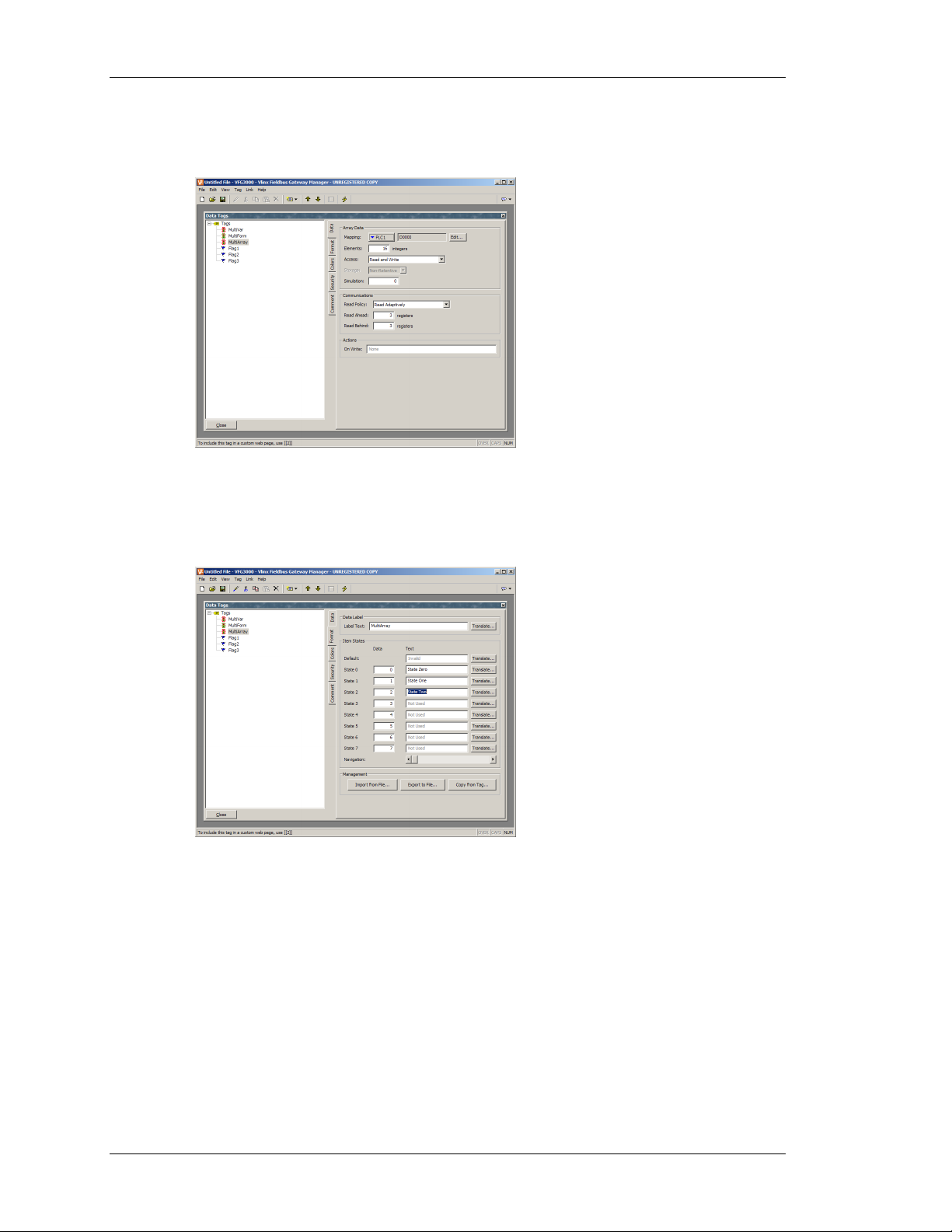
EDITING MULTI TAGS VLINX FIELDBUS GATEWAY MANAGER USER MANUAL
THE DATA TAB (ARRAYS)
The Data tab of a multi array contains the following properties...
All of these properties are as described for flag arrays.
HE FORMAT TAB
T
The Format tab of a multi tag contains the following properties...
• The Label Text property is used to specify the label that can be shown next to
this tag when including the tag on a display page. The label differs from the tag
name, in that the former can be translated for international applications, while
the latter remains unchanged and is never shown to the user of the Gateway.
• The Item States properties are used to define up to eight values that represent
different states of the tag. Each state has an integer value associated with it, and a
text string to indicate what should be displayed when the tag holds that value. At
least two states must be defined, but the balance may be left in their default
condition if they are not needed.
• The Default property is used to define the text to be displayed if the tag holds a
value other than one of those listed in the item states.
PAGE 70
Page 87

CONFIGURING DATA TAGS EDITING MULTI TAGS
• The Navigation slider is used to step through the 512 states that can be defined
for a particular tag. Moving the slider left and right will update the right-hand
pane to show the selected states.
The Export to File button can be used to export state names and values to a CSV file…
The CSV file will contain a line for each defined state, stating the state label, the state value,
and the text assigned to that state. If multiple languages are in use, an additional column will
be provided for each language. The file type drop-down can be used to select a Unicode
format file if you are using languages that cannot be represented in standard ASCII. The file
can be subsequently re-imported using the Import from File button.
The Copy from Tag button will display the following dialog box…
This dialog can be used to select another multi tag from which the format information is to be
copied. This facility will save a lot of typing if the same format is to be used on several tags.
REVISION 1 PAGE 71
Page 88

EDITING MULTI TAGS VLINX FIELDBUS GATEWAY MANAGER USER MANUAL
THE COLORS TAB
The Colors tab of a multi tag contains the following properties…
• The various color pairs are used to specify how the tag should be displayed when
it is each of the states specified on the Format tab. As with the Format tab, the
Navigation slider can be used to up and down the list of color pairs when more
than eight states have been defined.
HE ALARM TABS
T
Each Alarm tab of a multi variable or formula contains the following properties...
• The Event Mode property is used to indicate the logic that will be used to decide
whether the alarm should activate. The table below lists the available modes.
MODE
State Match The value of the tag is equal to the alarm’s Value.
State Mismatch The value of tag is not equal to the alarm’s Value.
ALARM WILL ACTIVATE WHEN…
• The Value property is used to define the comparison data for the alarm.
PAGE 72
Page 89

CONFIGURING DATA TAGS EDITING REAL TAGS
• The remainder of the properties are as described for the Alarms tab of flag tags.
T
HE TRIGGERS TAB
The Triggers tab of a multi variable or formula contains the following properties...
• The Trigger Mode property is as described for the Alarm tabs.
• The Delay property is as described for a flag tag’s Alarms tab.
• The Action property is used to indicate what action should be performed when
the trigger is activated. Refer to the Writing Actions section for a description of
the syntax used to define the various actions that Fieldbus Gateway Manager
supports.
EDITING REAL TAGS
You will recall that real tags represent a single-precision floating-point value. All the tabs
displayed for real tags are exactly the same as those displayed for integer tags, with the
exception that data entered for items such as the value and hysteresis properties of alarms and
triggers may contain decimals. You are thus referred to the sections on integer tags. You will
notice some selections for integer tags that are not applicable to real tags.
EDITING STRING TAGS
You will recall that string tags represent an item of text, this being made up of a number of
individual characters. The following sections describe the various tabs that are displayed on
the right-hand side of the Data Tags window when editing one of the various string tags.
REVISION 1 PAGE 73
Page 90

EDITING STRING TAGS VLINX FIELDBUS GATEWAY MANAGER USER MANUAL
THE DATA TAB (VARIABLES)
The Data tab of a string variable contains the following properties...
• The Mapping property is used to specify if the variable is to be mapped to a
register in a remote device, or if it exists only within the terminal. If you press
the arrow button and select a device name from the resulting menu, you will be
presented with a dialog box that will allow a PLC register to be selected.
• The Encoding property is used to specify how text will be packed into mapped
registers that contain more than 8 bits of data. Selecting unpacked will store one
character per register no matter how large the register, leaving the high-order bits
empty. Selecting low-to-high packed mode will store one character in each 8 bits
of the target register, storing the first character in the lowest order bits. Selecting
high-to-low packed mode will store one character in each 8 bits of the target
register, storing the first character in the highest order bits.
• The Length property is used to indicate how many characters of storage should
be allocated for this string. A value need only be entered if you have configured
the variable for retentive storage. Strings that are kept in the terminal’s RAM and
not committed to FLASH have no practical limit on their length.
• The remainder of the properties are as described for flag variables.
PAGE 74
Page 91

CONFIGURING DATA TAGS EDITING STRING TAGS
THE DATA TAB (FORMULAE)
The Data tab of a string formula contains the following properties...
• The Tag Value property is used to specify the value represented by this tag. It is
typically set to a combination of other tags, linked together using math operators
or functions. In the example above, the tag is set equal to the combination of two
strings variables, separated by a space. For more information on the operators
and functions that can be used with strings, refer to the Writing Expressions
section and the Function Reference at the end of this document.
• The Simulation property is as described for flag variables.
HE DATA TAB (ARRAYS)
T
The Data tab of a string array contains the following properties...
• The Length and Encoding properties are as described for string variables.
• The remainder of the properties are as described for flag arrays.
REVISION 1 PAGE 75
Page 92

EDITING STRING TAGS VLINX FIELDBUS GATEWAY MANAGER USER MANUAL
THE FORMAT TAB
The Format tab of a string tag contains the following properties...
• The Label Text property is used to specify the label that can be shown next to
this tag when including the tag on a display page. The label differs from the tag
name, in that the former can be translated for international applications, while
the latter remains unchanged and is never shown to the user of the Gateway.
• The Template property is used to provide a “picture” of the string, thereby
indicating what kind of characters can occur in each position. If a template is
specified, data entry will be limited such that only the correct kind of character
can be selected for each character in the string. The table below shows the
meaning of the various special characters that can be included in a template…
Character Permitted Characters
In Template A-Z a-z 0-9 Space Misc
A Yes - - - -
a Yes Yes - - -
S Yes - - Yes -
s Yes Yes - Yes -
N Yes - Yes - -
n Yes Yes Yes - -
M Yes - Yes Yes -
m Yes Yes Yes Yes -
0 - - Yes - -
X Yes Yes Yes Yes Yes
The additional characters referred to by the “Misc” column are…
,.:;+-=!?%/$
Characters not included in the table are copied verbatim to the display.
For example, to allow entry of a US telephone number, use a template of…
(000) 000-0000
PAGE 76
Page 93

CONFIGURING DATA TAGS MORE THAN TWO ALARMS
The parentheses, the space and the dash will all be included when the field is
displayed, but only the 10 digits indicated by the ‘0’ characters will be stored in the
string. Similarly, if data entry is enabled for a field using this template, the cursor
will skip the various non-numeric positions when moving left or right, and will only
allow numeric characters to be entered for those positions that can be selected.
• The Length property is used in lieu of the template to indicate how many
characters should be reserved on a page when displaying this string. If a string
variable is marked as retentive, it makes sense for this property to be equal to the
length entered on the Data tab, but this is not obligatory, as you may want to
allocate more or less space on the display for layout purposes.
• The Justification property is used when a template is not specified, and indicates
how strings shorter than the Length property should be positioned within the
storage allocated for the string. It is distinct from the Justification property of the
display format, in that it impacts the data that is actually stored.
HE COLORS TAB
T
The Colors tab of a string tag contains the following properties…
The tab is used to specify the default colors to be used to display this tag.
MORE THAN TWO ALARMS
If your application requires more than two alarms (or indeed triggers) for a tag, define a
formula to be equal in value to the primary tag, and set the extra alarms on the alias. For
example, if you have a variable called
need to create a third alarm for that tag, create a variable called, say,
value property to
Level. You can then set additional alarms on this alias tag.
Level which is mapped to N7:100 in a PLC, and you
LevelAlias and set its
VALIDATING TAGS
Selecting the Tags icon in the left-hand pane of the Tags window will allow access to the
Validate All Tags button. Pressing this button will recompile all expressions in your database,
fixing any broken communications references and updating tag reference counts. You should
REVISION 1 PAGE 77
Page 94

EXPORTING TAG MAPPINGS VLINX FIELDBUS GATEWAY MANAGER USER MANUAL
not need to push this button unless you have removed and then replaced tags, and wish to
repair the expression that will have been broken when the tags were deleted.
EXPORTING TAG MAPPINGS
Selecting the Tags icon in the left-hand pane of the Tags window will also allow access to the
tag import and export facilities. The Export to File button can be used to export the tag names
and mappings to a CSV file for subsequent editing in Microsoft Excel or some other suitable
tool. The Import from File button can then be used to re-import the file, changing the tag
mappings in line with the changes made to the file. These facilities are useful when porting an
application from one PLC to another, as it allows all the mappings to be changed in a single
operation. The import facility can also be used to create tags to correspond to data mappings
that have been exported into a CSV file from a B&B Electronics Modular Controller.
LOGGING EVENT MESSAGES
When the Tags icon is selected in the left-hand pane, the right-hand pane of the Tags window
contains options to control the logging of the messages generated by the alarms and events
attached to each tag…
• The Send to Raw Port property is used to indicate which communications port
events should be printed to. The port in question must have a raw port driver
bound to it as described in the Using Raw Ports chapter. Note that a serial driver
or a TCP/IP driver may be used as required by the application.
• The Save to CompactFlash property is used to enable the writing of events to
CSV files on the card fitted to the Gateway. Events are stored using techniques
similar to those for data logging. The New File Every and Retain at Most
properties control how files are allocated. Refer to the Configuring Data Logging
chapter for information on how the data is written and how files are named.
PAGE 78
Page 95

CONFIGURING A VIRTUAL HMI CONTROLLING THE VIEW
CONFIGURING A VIRTUAL HMI
Now that you have configured your communications options, and created data tags for the
various items that you wish to display, you can create display pages to allow the user to view
or edit these data items. These pages are manipulated by selecting the User Interface icon
from the main screen.
CONTROLLING THE VIEW
By default, the User Interface window attempts to show the entire front panel of the Fieldbus
Gateway’s virtual HMI, including the display and all the available fixed keys. In many cases,
this will not allocate enough screen space for the display to be edited, so you will probably
want to use one of the other zoom levels as shown below…
As you can see, at each level, fewer keys are shown, and more of the window is allocated to
the display itself. The view level can be controlled from the View > Panel menu, or by using
the panel icon
OOM FUNCTION
Z
, or by pressing the Alt key together with the digits 1 through 4.
In addition to the panel views, a zoom is available to help graphic designs. Zooming in and
out can be achieved from the View > Zoom menu, or by using the magnifying glass icon
or by rolling your mouse wheel up or down.
The Zoom will center on the mouse cursor so you can control which area of the screen you
are zooming to. There are four levels of zoom. The highest level would give the following
screen for the above database.
,
Due to screen resolution and virtual HMI size, it might not be possible to visualize the entire
screen design even when zoomed out. It is possible however to get this view using the View >
Panel > Show All Screen menu. This menu is only available when the view is NOT in display
REVISION 1 PAGE 79
Page 96

USING THE PAGE LIST VLINX FIELDBUS GATEWAY MANAGER USER MANUAL
only mode. Editing of the screen however will not be available in this mode since the screen
resolution is too small for accurate drawings.
OTHER VIEW OPTIONS
As well as controlling the zoom, the View menu contains the following options…
• The Page List command can be used to show or hide the left-hand pane of the
User Interface window. If the page list is disabled, even more space is made
available for editing the display. The
F4 key toggles the page list on and off.
• The Hold Aspect command can be used to control whether or not Fieldbus
Gateway Manager attempts to maintain the aspect ratio of the display. If aspect
holding is enabled, a figure that would appear as, say, a circle on the Gateway
will appear as a perfect circle on your PC. If this mode is not selected, Fieldbus
Gateway Manager can expand the display page to use more of the PC’s screen,
but at the expense of some distortion.
Other options are available during page editing, and are described below.
USING THE PAGE LIST
To create, rename or delete display pages, click on the left-hand pane of the User Interface
window. The various commands on the Page menu can then be used to make the desired
changes. Alternatively, right-click on the required display page, and select from the menu.
To select a page, either click on the page in the page list, or use the up and down arrows in the
toolbar. Alternatively, you can use the
Alt+Left and Alt+Right key combinations to move
up and down the list as required. These keys will work no matter which pane is selected.
PAGE 80
Page 97

CONFIGURING A VIRTUAL HMI WORKING WITH THE GRID
WORKING WITH THE GRID
The Show Grid command on the View menu can be used to show or hide an eight-pixel grid
that is useful for aligning objects. Every eighth column of the grid is shown in a brighter
color, as is every sixth row. Various drawing operations may be configured so as to “snap” to
the grid points whether or not the grid is shown,. The three separate actions of creating
objects, moving objects and sizing objects may be controlled individually, or the Snap for All
or Snap for None commands may be used to control all three actions at once.
THE DRAWING TOOLBOX
To edit the contents of a display page, first select the page as described
above. Then, click on the rectangle that represents the Gateway’s
display. A white rectangle will appear around the display to indicate
that it has been selected, and the drawing toolbox will appear.
This toolbox is used to add various elements, known as primitives, to
the display page. The first two icons control the insertion mode, while
the balance of the icons represent individual primitives. The primitives
shown in yellow are basic geometric and animation items, while the
ones shown in green are rich primitives that use formatting and other
information from a data tag to control their operation. The primitives
shown in red are system items, such as the active alarm viewer.
Primitives shown in blue are typically enhanced versions of other
primitives that were added to the software more recently.
All of the commands contained in the toolbox can also be accessed via the Insert menu.
ADDING DISPLAY PRIMITIVES
To add a display primitive to a page, click on the required icon in the drawing toolbox, or
select the required option from the Insert menu. The mouse cursor will change to an arrow
with a crosshair at its base, and you will then be able to drag-out the required position of the
primitive within the display window…
REVISION 1 PAGE 81
Page 98

ADDING DISPLAY PRIMITIVES VLINX FIELDBUS GATEWAY MANAGER USER MANUAL
SMART ALIGNMENT
If you have the Smart Align features of the View menu enabled, Fieldbus Gateway Manager
will provide you with guidelines to help align a new primitive with existing primitives, or
with the center of the display. In the example shown above, the horizontal dotted line
indicates that the center of the tank primitive is vertically aligned with the center of the
display. With a little practice, this feature can make it very easy to align primitives as they are
created, without the need to go back and “tweak” your display pages to get the various figures
into alignment.
In the example shown below, a newly-created ellipse is being aligned with two rectangles…
Guidelines are present at both the edges of the figures, and at the center, showing that both
the edges and the centers are aligned. The red rectangle is highlighting the newly-created
primitive, while the blue rectangles are highlighting the primitives to which the guidelines
have been drawn. Smart Align is also enabled when primitives are moved or re-sized.
EYBOARD OPTIONS
K
While creating a display primitive, the following keyboard options are available…
• Holding down the
Shift key while dragging-out the primitive will cause the
primitive to be drawn such that it is centered on the initial mouse position, with
one of its corners defined by the current mouse position. (If this doesn’t make
sense, go ahead and try it—it’s a lot easier to see than it is to explain!) This is
useful for drawing symmetrical figures centered on an initial point.
• Holding down the
Ctrl key while dragging-out the primitive will keep its
horizontal and vertical sizes the same. This is useful when you want to be sure
that you draw an exact circle or square using the ellipse or rectangle primitives.
These options are also active when primitives are re-sized.
OCK INSERT MODE
L
The padlock icon on the drawing toolbox can be used to add a number of primitives of the
same basic type without having to click the toolbox icon for each item in turn. To cancel lock
PAGE 82
Page 99

CONFIGURING A VIRTUAL HMI USING THE IMAGE LIBRARY
mode, click the padlock icon again, or press the Escape key. The same operation can be
performed by using the Lock Mode command on the Insert menu.
USING THE IMAGE LIBRARY
To add an image from Fieldbus Gateway Manager’s extensive image library, click on the
“book” icon in the toolbar, or select the Picture / Image command from the Insert menu. The
image library will open at the last-accessed page, allowing an image to be selected…
Double-click on an image to select, and then drag-out the required size of the image as you
would when inserting any other kind of primitive. The software will automatically create a
Picture primitive containing the selected image. You should refer to the later sections of this
manual for details on how this primitive might be further manipulated.
SELECTING PRIMITIVES
To select a display primitive, simply move your mouse pointer over the primitive in question,
and perform a left-click. You will notice that while your pointer is hovering over a primitive,
a bounding rectangle is drawn in blue to help show what will be selected. When the actual
selection is performed, the rectangle will change to red, and handles will appear, so as to
allow you to re-size the primitive as required. If you find that the primitive you want to select
is hidden below another primitive, press the
To select several primitives, either drag-out a selection rectangle around the primitives you
want to select, or select each primitive in turn, holding down the
you want each primitive to be added to the selection. If multiple primitives are selected, the
red rectangle will surround all of the primitives, and the handles can then be used to resize the
primitives as a group. The relative size and position of the primitives will be maintained, as
long as Fieldbus Gateway Manager can do so without violating minimum size requirements.
Alt key to allow the selection to be made.
Shift key to indicate that
MOVING AND RESIZING
Primitives can be moved by first selecting them, and then by dragging them to the required
position on the display page. If Smart Align is turned on, guidelines will appear to help you
align the primitives with other items on the page. Holding down
REVISION 1 PAGE 83
Ctrl while moving a
Page 100

ALIGNING PRIMITIVES VLINX FIELDBUS GATEWAY MANAGER USER MANUAL
primitive will leave a copy of the primitive in its original position, thereby allowing
duplicates to be created. You can also use the cursor keys to “nudge” the current selection a
single pixel in the required direction. Holding down
Ctrl while nudging will increase the
movement of the primitives by a factor of eight.
Primitives can be resized by selecting them, and then by dragging the appropriate handle to
the required position. Once again, if Smart Align is turned on, guidelines will appear to help
you align the primitives with other items on the page. The
Shift and Ctrl keys can be used
to modify the resize behavior as described in the Adding Display Primitives section. Note that
Fieldbus Gateway Manager will always constrain resizing operations so as to ensure that
primitives stay on the screen, and to make sure that items do not exceed their maximum
permitted size, or shrink below the minimum size appropriate to their format.
ALIGNING PRIMITIVES
While the Smart Alignment options discussed above allow many alignment operations to be
performed by hand, there are times that you will want the software to perform the alignment
for you. This can be done by selecting a number of primitives, starting with the primitive that
you wish to use as the reference point for the alignment operation. Note that the reference
primitive is always shown with a double-square at its center. Once you have made your
selection, use the Align command on the Arrange menu to display the following dialog box…
The Horizontal and Vertical settings can be used to indicate what type of alignment is to be
performed, while the Operation setting indicates whether the primitives should be resized or
moved to achieve the desired result.
As an example, in Move mode, selecting Left for Horizontal will align the left-hand edges of
all the primitives with the left-hand edge of the reference primitive. Similarly, selecting
Middle for vertical will align the primitives so that the horizontal line through the center of
each are aligned with the same line through the center of the reference primitive.
In Size mode, the edge-alignment operations work by growing the non-reference primitives in
order to achieve the desired results, while the center-alignment operations work by changing
the height or width of the primitives to make them match the reference primitive. You may
want to experiment with Size mode to get a better idea of its operation.
SPACING PRIMITIVES
If you have a number of primitives that you wish to space equally on the page, you may use
the Space Equally Vertical or Space Equally Horizontal commands on the Arrange menu. The
PAGE 84
 Loading...